Abstract
D-type shaft is widely used in precision machinery products such as motors and intelligent robots. The straightness of the D-type shaft is an important factor influencing its machining accuracy and dynamic performance, which is normally improved by the three-point pressure straightening process. This paper proposes a general stroke-based model to predict the relevant parameters for the straightening process of D-type shaft, considering the bending deformations in three dimensions. The distribution of stress and strain inside the D-type shaft during the straightening process in arbitrary position of the cross section and the bending moment are analyzed by using linear hardening material model. The relationship between deflection and the internal stress on the loading position is explored, and a straightening stroke model of D-type shaft is obtained. The correctness of the stroke-based straightening model has been validated by finite element method (FEM) simulation analysis and bending experiments. The results show that the proposed model can improve the accuracy and efficiency of the D-type shaft straightening process. Furthermore, it provides a novel method for the modelling of the straightening process regarding the special shaped bar stock.
1. Introduction
Shaft components have a variety of structural forms in practical applications, and D-type shaft is one of the common structural forms. The D-type shaft refers to a pure cylindrical shaft that is milled in the axial direction by a plane and forms the special shaft type. Its cross section looks like a letter “D” from the axial direction as shown in Figure 1. The D-type shaft has many applications, mainly for transmission and support components in various mechanisms. D-type shafts are generally used in mechanical products such as motors, small robots and automobile gears. The D-type shaft mechanism is generally at the ends of motor shaft or gear shaft and is used to output the torque and connect the coupling. The D-type characteristics on the shaft can position and guide the assembled parts, as well as transmit motion.
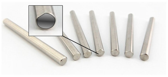
Figure 1.
D-type cross section shafts.
As an important part of the mechanisms, D-type shaft must ensure the output torque and the supporting stability. In order to obtain the designed performance, there are many technical requirements for machining the D-type shaft components, such as run-out tolerance, axiality tolerance, and straightness, which are influenced by machining and heat treatment, resulting in unpredictable bending deformation. Therefore, straightening is a crucial step in the D-type shaft machining process.
The straightening process is actually the process employing the capacity of plastic deformation of the metal material, in which the machined part experiences the elastic bending stage, elastic-plastic bending stage and the springback after the whole loading stage [1,2]. Through the theoretical analysis of the straightening process, based on the elastic-plastic bending theory, straightening models such as curvature and load straightening parameters have been obtained [3].
The D-type shaft is a special section form of shaft. The complicated milling and turning of shaft parts will influence the deformation behaviors [4]. The analysis of elastic-plastic bending process is the basis of the straightening model. Pei et al. [5] established a D-type shaft model for a special type of cross section based on the elastic-plastic bending theory, assuming the bending deformation only occurs on the plane of the D-type parts. Ma et al. [6] analyzed the phenomenon of neutral layer shift during the elastic-plastic deformation, which is helpful for the curvature research of the special section shaft straightening process. The elastic-plastic analysis and mathematical modeling were explored for different parts, and several straightening algorithms were developed based on the curvature and load control [7,8,9]. Zhang et al. [10] established a straightening stress model based on elastic-plastic deformation theory and material loading characteristics.
Establishing a straightening model based on straightening load is a common method for the straightening process. Some scholars established a load model of the beam bending process based on elastic-plastic bending and analyzed the bending behaviors under different loads [11,12]. Chakrabarty et al. [13] analyzed the strain changes during sheet elastic-plastic deformation and established a plane strain model. Based on the analysis of elastic-plastic deformation, straightening models with different parameters can be obtained for simple cross-section parts. Kosel [14] established the load-deflection model of beam. Galvis et al. [15] also solved pressure control during straightening process based on elastic-plastic deformation analysis. However, straightening machinery cannot accurately control the straightening load due to its sensors and mechanisms.
In the straightening model, the bending curvature of the workpiece is the key variable to control the straightening process. Natarajan [16] established a moment-curvature relationship, in which the straightening process parameters of the strip was explained. Kim et al. [17] used fuzzy self-learning to calculate the bending curvature of the yaw axis and optimized it according to the multi-step straightening process. However, it is difficult to measure and control the bending accurately during straightening process.
In this paper, considering the three-dimensional deformation caused by the “D”-section shape, a general stroke-based modelling approach is proposed to predict the straightening parameters of the D-type shaft. Based on the three-dimensional, the variations of the bending moment for the arbitrary position on the D-type section during straightening are analyzed. Based on the analysis of the loading and unloading processes, the straightening stroke model of the three-point straightening process is established, to predict the straightening parameters of the D-type shafts. The proposed stroke-based straightening model clearly explains the relationship between the straightening stroke and the initial deflection and is conducive to the precision control of the straightening process. Finally, the stroke-based straightening approach is validated by simulation and experiments. Finite element method (FEM) simulation and experimental research show the correctness of the proposed straightening principle for the D-type shaft.
2. Deformation during the Straightening Process
During the processing of the D-axis, the coupling of turning and milling causes unknown deformation to the part [4]. Material properties, heat treatment processes, and other conditions also cause deformation to the part after processing [17]. During the machining of the D-type shaft, the uneven machined surface causes the cutting force to be unstable and the machining stress is produced. If the machining stress is not eliminated in the subsequent process, the residual stress is produced. Unstable cutting forces and residual stresses cause bending to the D-type shaft. Where heat treatment process of the D-type shaft is mainly affected by the material properties. The temperature inside the shaft changes unevenly, resulting in bending deformation during cooling.
There are many factors that cause the D-type shaft to bend, and the cross-section of the D-type shaft is irregular. Therefore, the processed D-type shaft forms a three-dimensional deformation, and a general straightening stroke model is required during the straightening process. The deformation direction of the D-type shaft is shown in Figure 2. When the direction of deformation of the D-type shaft is different, the cross-sectional form of the D-type shaft is also different. Some factors in the process of bending deformation analysis are related to the form of the section. Therefore, the cross-section form of D-type shaft in different deformed directions should be considered in the process of the establishment about the D-type shaft straightening stroke model.
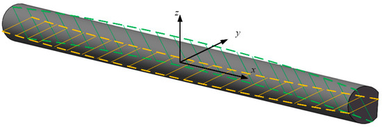
Figure 2.
D-type shaft deformation.
The state of the D-type shaft straightening is shown in Figure 3; the workpiece is placed between the press head and the support. The D-type shaft undergoes elastic-plastic deformation under the action of the press head.
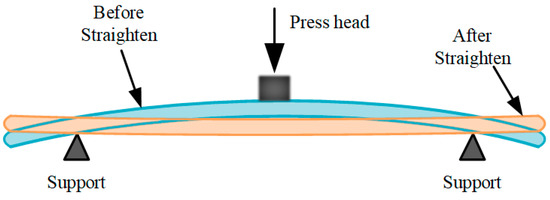
Figure 3.
Diagram of press straightening principle.
With the theory of mechanics of materials, neutral layer is not deformed when the D-shaft bending. In the cross section, the length of each fiber layer changes except for the neutral layer. Assuming that the position of the neutral layer is the origin, and z is the change direction of the elastic region, which is expressed as . Where is strain, is stress, and is the Young’s modulus. With the theory of the plane assumption, the strain is linearly distributed in the direction. The strain at layer in Figure 4 is written as
where is the reciprocal of the curvature angle .
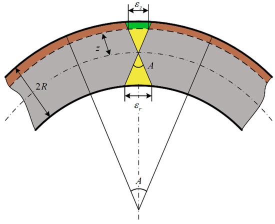
Figure 4.
Schematic diagram of bending cross section strain distribution in a usual shaft.
Figure 5 shows the curvature change during bending deformation at the layer [16]. The curvature with the unit length of the D-type shaft before straightening is assumed to be , and the curvature of the D-type shaft after bending is . Due to the action of the pressure head, the total curvature change of the workpiece is assumed as , which is written as
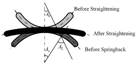
Figure 5.
Curvature diagram of bending process.
3. Stroke-Based Modeling Principle for the Straightening Process
3.1. Elastic-Plastic Analysis
The straightening process utilizes the elastic-plastic deformation that occurs inside the D-type shaft. The general bending theory in references [18,19,20] can explain the elastic-plastic mechanical relationship inside the D-type shaft. With the increase of bending deformation, the D-type shaft is transformed from linear elastic deformation to nonlinear plastic deformation. When the pressure head is lifted from the shaft body, an elastically deformed spring back occurs. In the core area of the shaft, only elastic deformation and elastic resilience occur. There are residual deformations in other areas of the shaft. The stress-strain distribution is shown in Figure 6. The change distribution of stress and strain is composed of the elastic area and the plastic area. It is assumed that the area where the elastic deformation occurs during the straightening process is within of the neutral layer. is called the core elastic radius.
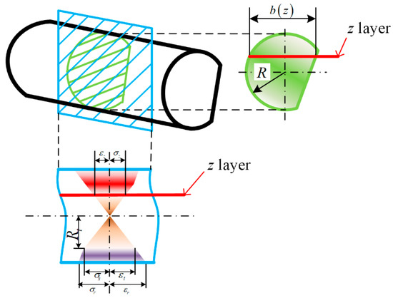
Figure 6.
Stress and strain distribution of D-type shaft.
The curvature when the outermost layer of the D-type shaft begins to undergo plastic deformation is defined as . As shown in Figure 5, represents the curvature value after straightening. In order to facilitate numerical calculation, the ratio of the curvatures is used as an intermediate variable, which can be written as
where the parameter can be defined as to represent the area where elastic deformation occurs.
By combining the linear hardening material model [18,21,22] to describe the stress-strain relation of the D-type shaft, the model is mainly composed of two areas [18,19,20]. A line with a fixed slope describes the first linear elastic deformation, and a second line with a fixed slope describes the hardening plastic deformation. As shown in Figure 7, the stress function can be written as
where is the plastic strengthening factor and is the Young’s modulus, which is determined by their material properties.
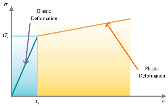
Figure 7.
The linear hardening materials model.
With Figure 6, the stress values of the deformation region can be obtained. The stress has a linear distribution along the bending cross section in the elastic area. The value can be written as
where is the yield limit. The stress has a linear distribution with another slope in the plastic deformation region. The value can be written as
According to the cross-sectional form of the D-type shaft, the cross section bending moment during straightening can be expressed by an integral function.
where represents the width of the section. and represent the height of the two endpoints on the cross section from the neutral layer along the direction. The elastic limit bending moment is defined as . To simplify theoretical analysis and unify variables into dimensionless parameters, a ratio of the bending moment is defined as
The ratio of bending moment indicates the state of elastic deformation and plastic deformation. The ratio of bending moment is an important parameter that characterizes the straightening state.
A cross section schematic diagram of the D-type shaft in an arbitrary straightened state is shown in Figure 8. In this figure, R is the radius of the section, e is the cut depth, γ is the angle between the cutting line and the horizontal line, and is the width of the section.
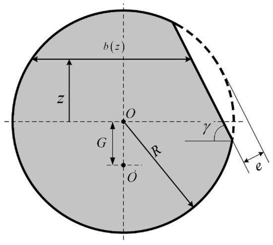
Figure 8.
The D-type shaft cross section.
Due to the three-dimensional deformation of the D-type shaft, the cross-section type of the D-type shaft is not determined; consequently, the width is not a definite value. The piecewise function describing the width is expressed as
(1)
(2)
where , and is the distance of the origin offset caused by the neutral layer movement of the D-type shaft. To simplify the calculation, the following parameters are defined as
According to the theory of material mechanics [18,19,20], the layer at point is the neutral layer of the cross section. Since the bending stress is linearly distributed from the neutral layer to both sides, the stress is balanced at the position of the neutral layer. This relationship can be expressed as
Substituting the parameters of the D-type shaft into Equation (15), the expression of the parameter can be obtained as
(1)
(2)
The parameter I is defined as the moment of inertia. According to the definition [18,19,20], the moment of inertia can be expressed as
(1)
(2)
Substituting Equations (5), (6), (9), and (10) into Equation (7), the bending moment within the section can be obtained. Substituting Equations (15) and (16) and the yield strength of the material into equation and then substituting the obtained parameter and the bending moment within the section into Equation (8), the bending moment ratio of the D-type shaft can be obtained. Different D-type shafts have different widths and moments of inertia; consequently, their bending moment ratios are also different. The bending moment ratios of the D-type shaft in two special forms are given. Figure 9 shows the cross-section types of two special D-type shafts.
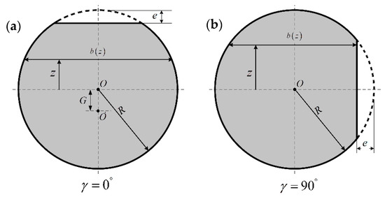
Figure 9.
(a) γ = 0° D-type cross-section and (b) γ = 90° D-type cross-section.
When γ = 0°, the cutting plane is on the horizontal position. Substitute γ = 0° into the Equations (9) and (10) to get the corresponding width equation. Then, according to the above-mentioned bending moment ratio derivation process, the ratio can be rewritten as
where .
When γ = 90°, the cutting plane is perpendicular to the horizontal axis in cross section. Substitute γ = 90° into the Equations (9) and (10) to get the corresponding width equation. The ratio of the bending moment can be rewritten as
(1)
(2)
3.2. Deflection Analysis of D-Type Shaft Straightening
The straightening stroke, which can control the variations of deflection, is an important parameter in the straightening process. With the theory of Cui et al. [18], the variations of D-type shaft deflection are expressed as shown in Figure 10. Supposed that the unit arc length at is , is the curvature, and is the radius of curvature. Since the variations of deflection are small, the unit length can replace the arc length .
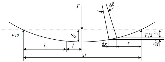
Figure 10.
Variations of the D-type shaft deflection.
With the theory of the plane assumption, the shear deformation is ignored, and the deflection caused by the downwards press force is written as:
With the Equations (17)–(19), the ratio of the bending moment is a function of the variable . After the D-type shaft reaches the elastic limit caused by the D-type shaft bending amount, plastic deformation occurs inside the D-type shaft. Among them, the portion of the D-type shaft necessarily has a length that only occurs elastic deformation. Therefore, the bending moment ratio under external load can be written as
The deflection during loading can be composed of plastic and elastic parts. The relationship between and can be established using an iterative method, and the deflection during loading can be composed of plastic and elastic parts. According to Equation (20), the deflection of the loading process with the numerical integration method can be rewritten as
where is the curvature ratio of point , and is the unit length set in the numerical integration solution, and is the inertia moment and F is the straightening force.
During the D-type shaft unloading process, the recovery linear elastic bending occurs. Ignoring the effect of the Bauschinger effect, there is no variations of Young’s modulus during the unloading process. Therefore, the deflection change in the unloading process is written as:
3.3. Straightening Stroke Model
The straightening stroke model obtained by theoretical derivation is expressed as
The Equation (24) is a combination of the Equations (21)–(23). Where is the straightening stroke and is the initial deflection. This theoretical model is derived based on the three-dimensional deformation. The parameter represents the moment model of arbitrary position on the D-type section. This theoretical model intuitively reflects the relationship between initial deflection and stroke in the straightening process. In the straightening process controlled by the stroke, the required straightening stroke can be directly solved based on the initial deflection of the D-type shaft.
According to the theoretical model, the influence of different D-type shaft cross section parameters is analyzed. The model is then expressed using graphs. Figure 11, Figure 12 and Figure 13 respectively show the influence of three important parameters on the theoretical model.
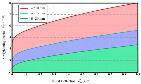
Figure 11.
Initial deflection and straightening stroke for the different D-type shafts (in relation to different radius).
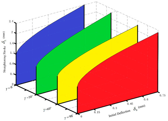
Figure 12.
Initial deflection and straightening stroke for the different D-type shafts (in relation to different angle).
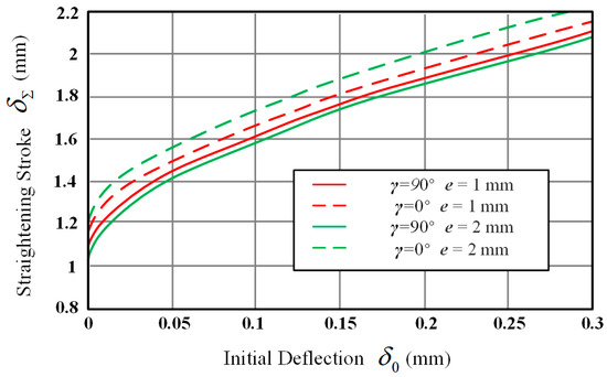
Figure 13.
Initial deflection and straightening stroke for the different D-type shafts (in relation to different cut depth and angle).
It can be seen from the graph that the angle, cut depth, and radius have different effects on the theoretical straighten stroke prediction model. Figure 11 shows the difference of the theoretical model when the radius R is different. It can be seen from the figure that the radius of the D-type shaft has a greater influence on the model. For the same initial deflection, the larger the radius R, the smaller the straightening stroke required. Figure 12 shows the effect of the difference in angle γ on the theoretical model. Results illustrate that the D-types straightening with a larger angle γ requires less straightening stroke. Figure 13 shows the effect of cut depth on the theoretical model. When the angle γ = 0°, the smaller the cutting depth, the greater the required straightening stroke, the angle γ = 90° is the opposite. The depth of cut has a greater influence on the angle γ = 0°.
4. Verifications
4.1. FEM Simulation Verification
4.1.1. FEM Model
According to the bending straightening principle and the existing experimental conditions, the three-dimensional model of D-type shaft straightening is established. In order to directly observe the changes of various parameters in the straightening process and to simulate the straightening process [23], the FEM is used to validate the correctness of theoretical straightening stroke model. The FEM software used for the simulation is ABAQUS (Version 6.13, Dassault Systèmes Simulia Crop., Providence, RI, USA, 2014). The FEM simulation is applied to study and analyze the deformation of D-type shaft during straightening process. The residual deflection and residual stress after straightening are analyzed, and the FEM simulation data and theoretical calculated data are compared.
The entire straightening system consists of three parts: D-type shaft, press head, and two supports. The radius of the D-type shaft model is 8 mm, the length is 300 mm, and the cutting depth is 2 mm. The two supports are fixedly constrained, and the span of the two supports is 280 mm. The initial pressure fixing of the D-type shaft is completed by displacement constraint on both end faces. The displacement control of the straightening is performed by applying a displacement constraint to the press head. Modeling and meshing of the straightening system are shown in Figure 14.
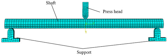
Figure 14.
Finite element method (FEM) model.
A Q235 material is established, and a linear hardening material model is established according to the material parameters that are shown in the Table 1.

Table 1.
The material properties.
4.1.2. Simulation Results
After calculation by ABAQUS 6.13, the residual deflection and residual stress after straightening are obtained as shown in Figure 15. It can be known from the simulation process that residual stress exists in the D-type shaft at the press head and support point after straightening. The simulation results show that the D-type shaft springbacks after straightening, and there is a quantitative residual deflection. Therefore, the straightening stroke can be controlled to achieve precise machining during the straightening process. Multiple sets of residual deflection data are obtained by altering the displacement constraints imposed on the press head. The residual deflection data and the corresponding straightening stroke data are recorded to compare the theoretically calculated data.
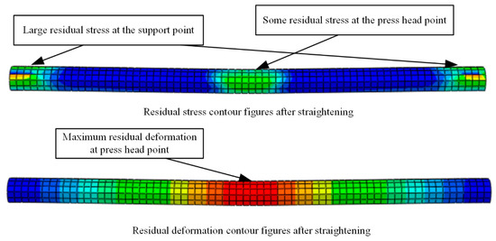
Figure 15.
Finite element analysis results picture.
Part of the data obtained from the FEM simulation and the theoretically calculated data are recorded in Table 2. It can be drawn from the data in Table 2 that the error between the theoretically calculated data and the simulated data is very small, which can prove the correctness of the theoretical model.
Table 2.
Comparison of FEM data and theoretical data.
4.2. Experimental Verification
4.2.1. Experimental Design
In order to prove the correctness of the calculation results of the theoretical straightening stroke model, an experimental study is carried out for the D-type shaft specimen [24]. In the current experiment, the testing machine in Figure 16 is used to simulate the straightening process. The testing machine is a DNS100 pressure tester machine produced in Shanghai. The power source of the testing machine is the servo motor, which carries out movement through the ball screw. The press head of the testing machine has a good speed control function and can reduce the effect of impact load on bending experiments. In this experiment, the press head is controlled by stroke because the testing machine has a high-precision displacement sensor, which can control the press head accurately. The maximum test force of the testing machine can reach 100 kN, and the displacement resolution can reach 0.01 mm, which satisfies the experimental requirements.
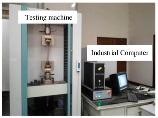
Figure 16.
Testing machine.
Multiple sets of D-type shaft specimens were prepared for this experiment. The radius of these shaft specimens was 8 mm. After processing, the cut depth was 2 mm, and the length was 300 mm. The material of these specimens was Q235, and the Young’s modulus and yield limit of these specimens was 210 GPa and 235 MPa, respectively. The support span of the testing machine selected for this experiment was 280 mm. The pressure of the testing machine was set to 800 N, and the speed of press head was set to 5 mm/min. After many experimental verifications, this constant pressure value can avoid the offset of the D-type shaft during the loading process, and it can ensure that the transformation from the elastic deformation phase to the elastic-plastic deformation phase can be completed during the D-type shaft straightening.
4.2.2. Experimental Process and Results
As shown in Figure 17, the experimental specimen is placed between the press head and the support. The specimen is fixed by the press head loading, and then the loading phase is entered. The stroke control mode is used to control the pressure of the press head at a uniform speed to reach the target stroke. After stability, the unloading phase is entered. The residual deflection data will be recorded until the pressure is zero. The experimental process is shown in Figure 18.
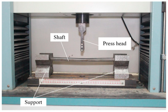
Figure 17.
Experimental scene layout picture.
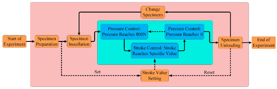
Figure 18.
Experimental flow chart.
The entire bending experiment process is repeated, and the experimental results are finally obtained. After completing the entire experimental cycle, the residual deflection of each D-type shaft is recorded. Part of the data in Table 3 is the experimental data of straightening stroke and residual deflection. The data in Table 3 compares the experimentally obtained residual deflection data with the theoretical model calculated data at the same straightening stroke. It can be drawn from the table that the theoretical calculation is close to the experimental data. It can be proved that the theoretical model can direct the actual straightening process, and the data also validate the correctness of the theoretical model. Each set of D-type shaft data regarding to straightening stroke and corresponding residual deflection is processed, and a relation curve between the D-type shaft of the straightening stroke and the initial deflection is established. It can be seen from Figure 19 and Figure 20 that the experimental data shows conformity with the theoretical and simulation data by comparing the three data, and the overall trend of the graph is consistent. The results of experiment and FEM simulation validate the correctness of the theoretical model.
Table 3.
Comparison of experimental data and theoretical data.
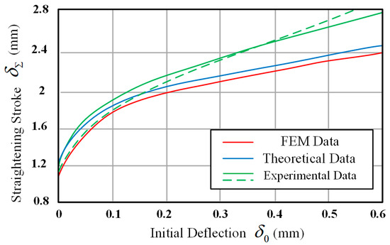
Figure 19.
Comparison of D-type shaft (γ = 0°) straighten stroke models.
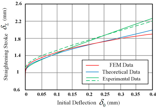
Figure 20.
Comparison of D-type (γ = 90°) shaft straighten stroke models.
5. Conclusions
This paper proposes a general stroke-based model to predict the parameters for D-type shaft straightening, considering the bending deformations in three dimensions, and based on the internal elastic-plastic mechanical analysis with the deflection variation of the D-type shaft. The influence of D-type shaft cross section parameters on the theoretical model is analyzed. As the radius R and angle γ of the D-type shaft increase, the required straightening stroke becomes smaller. The cutting depth has a greater influence on the case of γ = 0°, and as the cutting depth increases, the straightening stroke is smaller, whereas it is larger in the case of γ = 90°. The experimental results, FEM simulation results, and theoretical results prove the correctness of the theoretical stroke-based straightening model. The general stroke-based straightening modeling approach developed in this research can accurately predict the straightening parameters of complex cross-section part under three-dimensional deformation.
Author Contributions
Conceptualization, H.L. and Y.Z. (Yue Zang); methodology, X.Z. and Y.Z. (Yongquan Zhang); writing—original draft preparation, Y.Z. (Yue Zang); writing—review and editing, Y.Z. (Yue Zang) and Y.Z. (Yongquan Zhang); validation and data curation, L.L. All authors have read and agreed to the published version of the manuscript.
Funding
This research was funded by The National Natural Science Foundation of China (Grant no. 51675393), the Hubei Province Intellectual Property Guidance and Development Project (Grant no. 2019-1-76) and the Excellent Dissertation Cultivation Funds of Wuhan University of Technology (Grant no. 2018-YS-037).
Conflicts of Interest
The authors declare no conflict of interest.
References
- Zhang, Y.Q.; Lu, H.; Wang, Y.J.; Zhang, X.B.; Zhang, J.L.; Ling, H. Variable Span Multistep Straightening Process for Long/Extra-Long Linear Guideways. IEEE Access 2019, 7, 107491–107505. [Google Scholar] [CrossRef]
- Eggertsen, P.-A.; Mattiasson, K. On the modelling of the bending–unbending behaviour for accurate springback predictions. Int. J. Mech. Sci. 2009, 51, 547–563. [Google Scholar] [CrossRef]
- Megharbel, A.E.; Nasser, G.A.E.; Domiaty, A.E. Bending of tube and section made of strain-hardening materials. J. Mater. Process. Technol. 2008, 203, 372–380. [Google Scholar] [CrossRef]
- Sofuoğlu, A. Prediction of stable depth of cuts in turning and milling operations: A new probabilistic approach. J. Br. Soc. Mech. Sci. Eng. 2019, 41, 1007. [Google Scholar] [CrossRef]
- Pei, Y.C.; Wang, J.W.; Tan, Q.C. An investigation on the bending straightening process of D-type cross section shaft. Int. J. Mech. Sci. 2017, 131, 1082–1091. [Google Scholar] [CrossRef]
- Ma, L.F.; Ma, Z.Y.; Jia, W.T.; Lv, Y.Y. Research and verification on neutral layer offset of bar in two-roll straightening process. Int. J. Adv. Manuf. Technol. 2015, 79, 1519–1529. [Google Scholar] [CrossRef]
- Li, J.; Xiong, G.L. Study on calculation method of press straightening stroke based on straightening process model. Key Eng. Mater. 2007, 340, 1345–1350. [Google Scholar] [CrossRef]
- Lu, H.; Ling, H.; Leopold, J.; Zhang, X.; Guo, C.Q. Improvement on straightness of metal bar based on straightening stroke-deflection model. Sci. China Ser. E Technol. Sci. 2009, 52, 1866–1873. [Google Scholar] [CrossRef]
- Lu, H.; Zhang, Y.Q.; Gao, S.; Ling, H. Research on straightening stroke prediction model considering Stress Superposition. J. Huazhong Univ. Sci. Technol. (Nat. Sci. Ed.) 2016, 44, 65–70. [Google Scholar]
- Zhang, Y.; Lu, H.; Zhang, X.; Fan, W.; Ling, H.; Wei, Q.; Ma, M. A novel analytical model for straightening process of rectangle-section metal bars considering asymmetrical hardening features. Adv. Mech. Eng. 2018, 10, 1–14. [Google Scholar] [CrossRef]
- Tsai, S.H.; Kan, H.C. The exact solution of the load-deflection model of a uniformly loaded rectangular cross-section cantilever beam. J. Phys. D Appl. Phys. 2008, 41, 095502. [Google Scholar] [CrossRef]
- Tsai, S.H.; Wang, Y.T.; Kan, H.C. Analysis on the uniformly loaded rectangular cross-section cantilever by a modified load–deflection model. J. Phys. D Appl. Phys. 2009, 42, 045505. [Google Scholar] [CrossRef]
- Chakrabarty, J.; Lee, W.B.; Chan, K.C. An exact solution for the elastic/plastic bending of anisotropic sheet metal under conditions of plane strain. Int. J. Mech. Sci. 2001, 43, 1871–1880. [Google Scholar] [CrossRef]
- Kosel, F.; Videnic, T.; Kosel, T. Elasto-Plastic Springback of Beams Subjected to Repeated Bending/Unbending Histories. J. Mater. Eng. Perform. 2011, 20, 846–854. [Google Scholar] [CrossRef]
- Galvis, J.C.; Maury, H.E.; Hernandez, R.J. Elasto-plastic model to determine the maximum force for shaft straightening process. Ing. Investig. 2017, 37, 107–110. [Google Scholar] [CrossRef]
- Natarajan, A.; Peddieson, J. Simulation of beam plastic forming with variable bending moment. Int. J. Non-Linear Mech. 2011, 46, 14–22. [Google Scholar] [CrossRef]
- Kim, S.-C.; Chung, S.-C. Synthesis of the multi-step straightness control system for shaft straightening processes. Mechatronics 2002, 12, 139–156. [Google Scholar] [CrossRef]
- Cui, F. Straightening Principle and Straightening Machine, 2nd ed.; Met-Allergically Industry Press: Beijing, China, 2007; pp. 7–83. [Google Scholar]
- Li, J.; Xiong, G.L.; Zou, H.J. Process modeling and stroke calculation for shaft straightening. Heavy Mach. 2004, 6, 41–44. [Google Scholar]
- Chen, Z.X.; Chen, H.; Yang, K. A method of the calculation of straightening stroke for automatic precise pressure straightening. J. East China Jiaotong Univ. 2007, 2, 127–130. [Google Scholar]
- Gere, J.M.; Timoshenko, S.P. Mechanics of Materials, 3rd ed.; PWS-Kent Publishing Company: Boston, MA, USA, 1990; pp. 264–353. [Google Scholar]
- Hartley, P. Introduction to computational plasticity. J. Phys. A Math. Gen. 2006, 39, 3850–3851. [Google Scholar] [CrossRef]
- Hodhigere, Y.; Jha, J.S.; Tewari, A. Finite Element Analysis-Based Approach for Stress Concentration Factor Calculation. Proc. Fatigue Durab. Fract. Mech. 2018, 10, 1–6. [Google Scholar]
- Zhao, J.; Cao, H.; Zhan, P.; MA, R. Pure Bending Equivalent Principle for Over-bend Straightening and Its Experimental Verification. J. Mech. Eng. 2012, 48, 28–33. [Google Scholar] [CrossRef]


© 2020 by the authors. Licensee MDPI, Basel, Switzerland. This article is an open access article distributed under the terms and conditions of the Creative Commons Attribution (CC BY) license (http://creativecommons.org/licenses/by/4.0/).