Article

Aerodynamic Studies on Non-Premixed Oxy-Methane Flames and Separated Oxy-Methane Cold Jets

1
Department of Aerospace Engineering, Indian Institute of Technology, Kharagpur 721302, India
2
Department of Electrical Engineering, Institute of Infrastructure Technology Research and Management (IITRAM), Ahmedabad 380026, India
3
Department of Automation, Technical University of Cluj-Napoca, 400641 Cluj-Napoca, Romania
4
Department of Physics and Chemistry, Technical University of Cluj-Napoca, 400641 Cluj-Napoca, Romania
*
Author to whom correspondence should be addressed.
Processes 2020, 8(4), 429; https://doi.org/10.3390/pr8040429
Submission received: 11 March 2020 / Revised: 30 March 2020 / Accepted: 31 March 2020 / Published: 3 April 2020

Abstract

:
Both cold and flame jets find numerous applications in different fields, ranging from domestic applications to aerospace and space technology. Indeed, the applications of isothermal and non-isothermal jets in the flame heating industry fascinated the researchers to gain an in-depth understanding. Nevertheless, these benefits are not standalone, rather, they are associated with major disadvantages such as improper jet mixing and flame instabilities that require careful remedies. In the present investigation, three-inline jets, having methane jet at the center and two oxygen jets at the periphery, are studied computationally in a three-dimensional domain, with and without considering the effects of combustion. To study the mixing characteristics of cold jets, the radial velocity distributions at different streamwise locations have been analyzed at the jet inlet velocity of 27 m/s. However, for oxygen and methane flame jets, inlet velocities are varied as 27 m/s and 54 m/s. Moreover, to investigate the effects of temperature variation on mixing characteristics at a particular jet velocity, the inlet temperatures of reactants are varied as 300 K, 500 K, and 700 K, at the jet inlet velocity of 27 m/s. Combustion is found to have a profound impact on the mixing characteristics. At the inlet temperature of 300 K, a higher centerline velocity decay is observed for non-reactive jets as compared to reactive flame jets. Moreover, the turbulent kinetic energy distribution is relatively higher in the case of non-reactive jets, which is the direct evidence of an augmented mixing. As is obvious, the turbulent kinetic energy at the jet shear layer is maximum due to the formation of large-scale coherent eddies. The decay in centerline velocity is found to be increasing with an increase of inlet temperature. Additionally, with an increase of jet velocity, the radial velocity profiles become more asymmetrical, consequently yielding an unstable flame.

Graphical Abstract

Highlights

  • Mixing characteristics of three-inline non-premixed Oxy-methane flames have been investigated computationally at different inlet velocities and temperatures. Three-inline separated Oxy-methane cold jets were also studied for comparison.
  • The flame behavior is investigated by means of velocity and turbulent kinetic energy distributions at different streamwise locations.
  • Inlet temperature, inlet velocity, and combustion played a significant role in the mixing patterns of separated Oxy-methane jets.

1. Introduction

Jets are increasingly being used due to their several applications ranging from household to space applications [1]. Numerous advantages of both non-reactive and flame jets have motivated the researchers to study them in-depth for a long time. The jets are essentially characterized as the pressure-driven shear flow of a fluid which is being discharged into another fluid or the vacuum. Since fluid cannot withstand the pressure difference across it, the fluid layer near to jet boundary is commonly referred to as “free-shear-layer”. Initially, the shear layer, near the nozzle inlet, is thin, but due to viscous effects that cause entrainment of ambient fluid, the shear layer progressively becomes thicker as the jet propagates downstream. Due to the velocity difference across the shear layer, the fluid “rolls-up” and generates coherent vortices, eventually leading to the entrainment of surrounding fluid into the jet flow field. This fluid entrainment transports the “matter” along with it. Thus, to conserve the total momentum, the velocity of jet reduces and cross-sectional area increases. The jet finally diffuses into the surrounding fluid in the far-field.
In contrast to a single jet issued into the stagnant environment, the interaction of multiple jets of different velocities is more complicated due to shedding of different types of vortices and recirculated zones developed in the flow field. A typical schematic diagram of twin subsonic jets is shown in Figure 1. Notice that, a sub-atmospheric region is established between the jets just downstream of the nozzle exit. This region extends up to the point, called “merging point”, where the inner shear layers of individual jets are merged with each other. At far downstream locations, sufficiently away from merging point, the jets are completely mixed and behave as a single jet.
Unlike the aforementioned “isothermal” jets, when the temperature of the jet is different from the surroundings into which it is being issued, the jet is referred to as a “non-isothermal” jet. Based on the chemical reaction occurring in the combustor, non-isothermal jets are classified into non-reactive and reactive jets. The reactive jets are further classified into the pre-mixed and the non-premixed “flame jets” (or simply “flames”). Since the flames tremendously increase the amount of heat transfer, they are actively being used in the flame-heating industry. However, the efficacy of flames in enhancing the heat exchange process largely depends upon the mixing characteristics. Improper mixing of the multiple flames yields a non-uniform temperature profile, thereby, leading to an unstable flame.
Besides, the premixed flames are also associated with other anomalies such as flashback, high NOx formation, etc., making them less controllable [2,3]. Thus, from an improved controllability point of view, the non-premixed or separated jets are usually preferred. However, the simultaneous occurrence of mixing and combustion poses a challenge to the stability of the non-premixed flame.
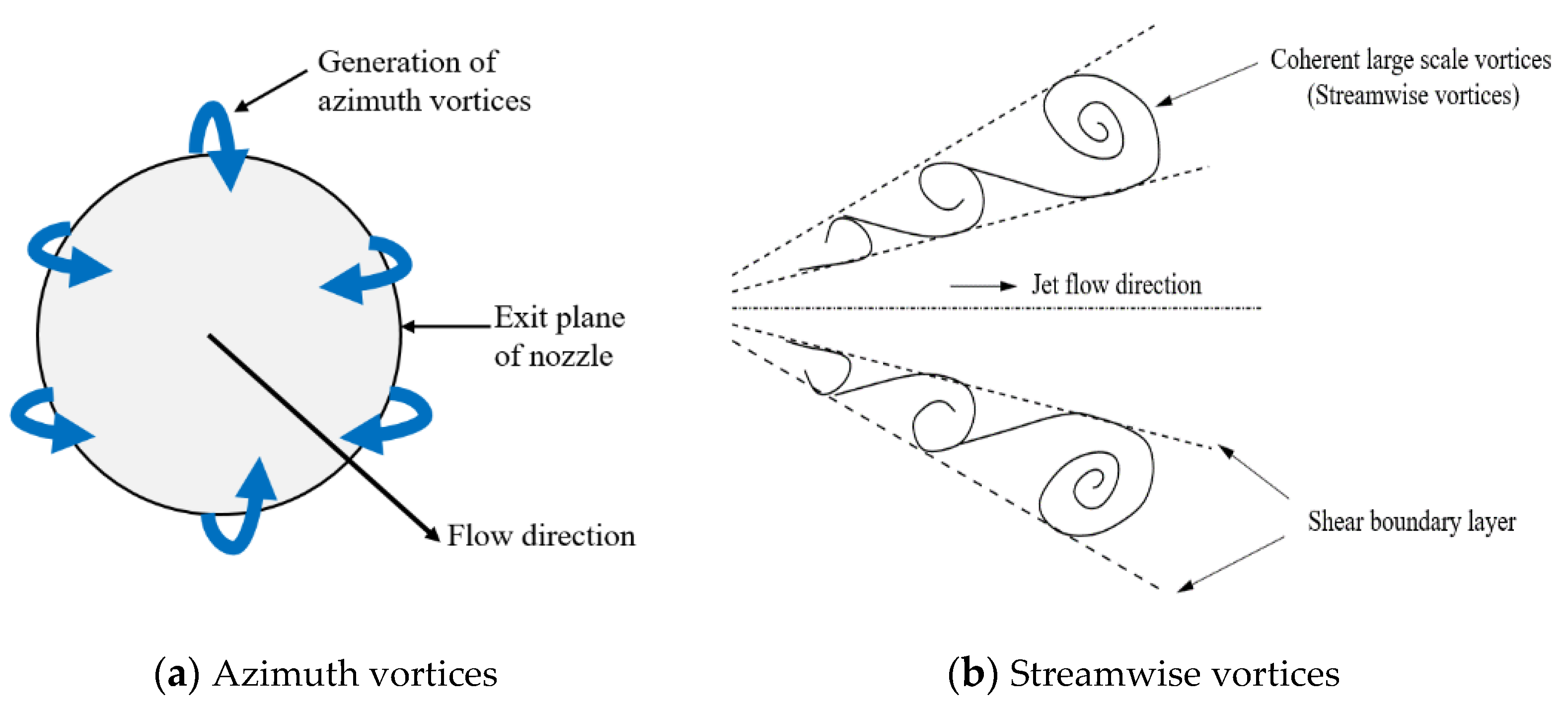
Gauntner et al. (1970) performed a comprehensive survey on turbulent impinging jet characteristics such as core length, jet spreading rate, centerline velocity decay, pressure distribution and turbulence distribution [4]. It was found that the mixing characteristics of non-reactive jets and stability of non-premixed flames are dependent upon the geometrical configuration, types of reactants and jet velocity distribution. These observations are further confirmed in the studies of Sreenevasan et al. 1982, Holdeman 1993, and Holdeman et al. (1995, 1999) [5,6,7,8]. Sreenevasan et al. (1982) found that when the spacing between the orifices is increased the mixing is delayed further downstream. Later, Holdeman (1993) and Holdeman et al. (1995, 1999) through their investigations on the non-reactive jets, they reported that the mixing characteristics of multiple jets are the strong functions of geometrical and flow parameters. Also, the density difference between the jet and its surrounding imposes a significant impact on centerline velocity decay and mixing rate; lower the density difference, higher the velocity decay as well as the mixing (Panchapakesan and Lumley 1993, Gazzah et al. 2002) [9,10,11]. Furthermore, a comparative study of Thring and Newby (1953) confirms that the centerline velocity decay is relatively low for reactive/flame jets than the non-reactive jets due to reduced mass entrainment rate. Also, at a higher temperature, the combustion products of smaller density entrain towards the reactive/flame jet axis, which in turn reduce the jet momentum and retards the reactive/flame jet decay [12]. Clemens and Paul (1995) found that the heat release rate due to the influence of flame improved the turbulent structures significantly by laminarizing them [13]. Rehm and Clemens (1999) observed that the velocity of non-reactive jet fluctuates relatively at a higher rate, as compared to the reactive jet. They observed that large-scale coherent structures are dominant in spreading of the non-reacting jets, however, they are ineffective in spreading of reactive jets [14]. Schematic diagrams showing the azimuth and the large-scale coherent structure (streamwise vortices) shedding are shown in Figure 2.
Recently, Kang et al. (2015) in their studies compared the lengths of dimethyl ether, methane, and LPG (Liquefied Petroleum Gas) diffusion flames, both in laminar and fully turbulent flow fields. They observed that by lowering the density of fuel jet dissipates at a faster rate and experiences reduction in the flame length [15]. Later, Bonelli et al. (2016) provided an important observation in the near and intermediate fields of the hydrogen circular jets. Three-dimensional Large Eddy Simulations with sixth-order compact finite difference scheme was adopted for discretizing the Navier-Stokes equations. They found that a higher ambient fluid density to the jet density ratio provides larger spreading. However, its effects are higher for centerline velocity decay than the jet spreading [16].
Raghunathan and Reid (1981) studied the mixing effectiveness of multiple jets. They found that a multijet configuration augments the mixing significantly, compared to a single jet [17]. Moreover, an experimental study on the multiple acetylene flames reveals that the geometrical spacing between the flames plays a vital role in flame stabilization. Increased spacing between the flames causes a reduction in flame length by promoting the mixing of oxygen and air. However, the flame length is found to be increasing with the increase of Reynolds number (Leite and Carvalho 1996) [18]. Furthermore, the combustion characteristics of multiple flames of the cross-flow situation were experimentally investigated by Menon and Gollahalli (1988) [19]. The flame length was strongly dependent on the number of parallel flames and the spacing between them. In this study, Oxy-fuel jets were specifically used owing to their higher reaction rate and high temperature, which eventually leads to a stable flame (Xing et al. 2015) [20]. Moreover, in the studies carried out by Sautet et al. (2001), a higher flame length and lower flame temperature are observed for air-methane flame jet as compared to Oxy-methane jet [21]. Also, the variation in flame length strongly depends on the effective mixing of reactant jets. Later, Sautet et al. (2006) proposed that the separated Oxy-fuel burner consists of a methane jet at the center surrounded by two oxygen jets on either side, have a favorable impact on flame stability and pollutant emissions. A considerable reduction in pollutant emission is observed when both the methane jet velocity and the separation distance are increased. Indeed, with an increase in separation distance, the flame length increases, eventually giving rise to a stable flame [22]. They also showed that the parameters like jet exit velocities, jet diameter, and separation distance have a great influence on the flame structure. These observations are consistent with those observed in other active flow devices like synthetic jet actuators and these need to be taken care of in the control of such devices [23,24,25].
Recently, the Oxy-fuel burner with three-separated jets placed in a row (a fuel jet at the center with two oxygen jets on either side) has gained prominence due to their compact design. Important experimental observations made by Boushaki et al. (2008, 2009) reveal that the inclination of the lateral oxygen jets towards the central fuel jet promotes mixing by shifting the jet merging point further upstream and thus stabilizes the flame. They found that the reactive jets experience higher radial spreading in comparison to the non-reactive jets [26,27].
Boushaki et al. (2011) studied the Oxy-fuel jets in parallel configuration experimentally. They confirmed that the flame stability is a strong function of the jet centerline velocity and jet spacing [28]. Subsequently, Hidouri et al. (2016) performed a finite volume computations on three inline jets with ventilation using second-order Reynolds stress model. The turbulent intensity at the inlet was considered as 10%. They observed that the ventilation reduces the recirculation zone near the nozzle exit. Furthermore, a comparison of the ventilated and non-ventilated jets showed that, due to ventilation, the root mean square values of the combined jet reduce and the flow stabilizes. However, the ventilation speeds up to 5 m/s cannot influence the far fields of the combined jet [29]. Besides, Mergheni et al. (2017) performed a two-dimensional computation on a three-inline Oxy-methane jet configuration. They noticed that, within the flammability limits, a decrease in the equivalence ratio essentially yields an efficient mixing of oxygen and fuel jets [30]. A recent study of the non-premixed combustion of Oxy-fuel jets in a co-flow configuration (the natural gas at the center and oxidizers at the periphery), revealed the rise in flame length with an increase of initial fuel velocity and oxidizer temperature. An increase in fuel jet velocity results in the higher fuel diffusion that extends the flame length in the combustion chamber. However, an increase in oxygen inlet temperature leads to a decrease in its density and turbulent viscosity. A decrease in turbulent viscosity, however, reduces the rate of mass entertainment but increases the flame length. On the other hand, for constant Oxy-fuel velocity, a decrease in the density of oxygen causes a reduction in the mass flow rate of the oxidizer and hence increases the equivalence ratio [31].
From the aforesaid discussion, it is clear that the geometrical configuration, kinetic conditions, types of reactants, and inlet temperature are vital in achieving a stable flame. Also, the parameters such as velocity distribution, turbulence level and turbulence intensity are essential to characterize the mixing pattern of the jets.
Although the aerodynamic characteristics of Oxy-methane flames are studied by several researchers, a thorough analysis in a three-dimensional domain has not been performed. In this study, the mixing characteristics of multiple jets, with methane jet at the center and two oxygen jets on either side are investigated in a three-dimensional computational domain. Both reactive and non-reactive jet configurations are examined to study the effects of combustion on the jet mixing.

2. Methodology

2.1. Numerical Domain

Numerical investigation of Oxy-methane inline jets is carried out inside a 100 mm × 60 mm × 60 mm flow domain, as shown in Figure 3. The methane jet is located at the center and the two oxygen jets are deployed on either side. Since the jets are axisymmetric and the calculations are carried out for steady flow, one-fourth part of the total flow zone is considered as the numerical domain, which indeed saves the computation time. Each jet has a diameter of 6 mm, and the spacing between the methane and oxygen jets is kept 12 mm. The axial length of the numerical domain is chosen as 100 mm. Note that, the numerical domain in this study was selected with anticipation to capture the near and intermediate flow fields characteristics of the combined jets. Besides, a three-dimensional numerical domain was specifically chosen since a mixing process is inherently three-dimensional.

2.2. Mesh Model

In the meshed model, both structured and unstructured hexahedral cells were used. From the grid sensitivity test, about 403,263 nodes were found suitable for the computations.

2.3. Boundary Conditions

The volume-based stoichiometric ratio of the oxygen and methane mixture is considered as 2.0. To validate the results with existing literature, the designed power of Oxy-methane combustion is chosen as 25 KW and thus the velocity of both oxygen and methane jets are found to be 27.13 m/s. The initial velocity of the jet is varied from 27 m/s to 54 m/s and the inlet temperature of the jet is varied as; 300 K, 500 K, and 700 K, to analyze the influence of these parameters on flame stability. The densities of methane and oxygen are 0.724 kg/m3 and 1.331 kg/m3, respectively. At the inlet, oxygen and methane have the mass fractions of 0.995 and 1, respectively. The outlet of the numerical domain is considered as the pressure outlet with zero gauge pressure. The walls along the X- and Y-axes are the axi-symmetric. For asymmetric walls, zero heat flux and no-slip conditions are imposed. Since turbulent intensity is a vital parameter in characterizing the potential core, about 10% intensity is assumed at the jet inlets. The boundary conditions are tabulated in Table 1.

2.4. Governing Equations and the Methodology

Three-dimensional Navier-Stokes equations are solved using the finite volume-based commercial solver Ansys Fluent. Computations are performed to solve the steady mass, momentum, energy, and species conservation equations for all the jets. The general form of the conservation equation is shown in Equation (1).
z ( ρ V ) + 1 r r ( r ρ V ) = z ( τ d dz ) + 1 r r ( r τ d dr ) + S
The Reynolds Average Navier-Stokes equation (RANS) is solved using k-epsilon turbulence closure model. The standard k-ɛ turbulence model is used to solve the transport equation of turbulent kinetic energy (k) and the dissipation rate (ɛ). Note that, the standard k-ɛ model uses the assumption of a fully turbulent flow. The value of the constant C in this turbulence model is 1.44, which is modified as 1.6 to predict the most accurate core length of the round jet (Pope 1978) [32]. Furthermore, the jet mixing rate decreases with an increase in C1ɛ value, which, however, underestimates the velocity decay, hence, for the present calculations, a constant value C1ɛ is taken without any modification. To solve the species transport equation, Eddy Dissipation Model (EDM) is used to account for the turbulent mixing. For pressure calculations, the steady pressure-based solver is used and the coupling of pressure and velocity is obtained from SIMPLE algorithm. First-order momentum and pressure discretization are adopted for numerical simulation. The residual convergence criteria for energy and continuity equations are 10-6 and 10-3, respectively. The first order upwind method is utilized for the discretization of the convection terms. For non-reactive jets also, the same numerical domain is considered, however, k-ɛ (realizable) turbulence model is used for analysis.
The commercial code Fluent is used to solve the species transport equation. For a general with species in the convection-diffusion equation, Fluent calculates the local mass fraction as Yi. The species conservation equation is given by Equation (2).
z ( ρ VY i ) + 1 r r ( r ρ VY i ) = z ( J i dY i dz ) + 1 r r ( rJ i dY i dr ) + R i + S i
where Ji and Ri, respectively, are the mass diffusion flux and the rate of generation of ith species due to chemical reaction. Si is a user-defined parameter.
The eddy viscosity is computed as,
μ t = ρ C μ K 2 ε
where Cµ is taken as constant (=0.09) for the standard k-ɛ model.
Following the single-step reaction model is used for the present calculations, which, however slightly overestimates the temperature.
CH 4 + 2 O 2 = CO 2 + 2 H 2 O

2.5. Grid Sensitivity Test

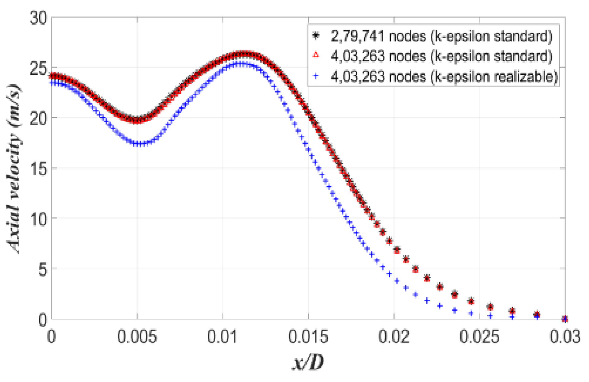
Two different numbers of nodes; 279,741 and 403,263 are used in the grid sensitivity test. The velocity profiles for two different grid spacing are shown in Figure 4. With k-ɛ standard model, no significant variations in the profiles are observed. Since a fine grid predicted the temperature more accurately, 403,263 numbers of nodes are finally used for the analysis. Furthermore, since Mergheni et al. (2017) demonstrated that the velocity profiles for reactive jets, computed with a realizable k-ɛ model, show a larger deviation, therefore, the standard k-ɛ model is only used. The maximum temperature for the stoichiometric oxy-methane composition is estimated to be 3240 K. NASA CEARUN online code is used for the validation purpose, which interestingly estimates the maximum temperature as 3050 K.

2.6. Validation

The velocity profile of three inline oxy-methane jets at the streamwise location of 8.33D is validated with the results obtained by Mergheni et al. (2017) [30], and the comparison is shown in Figure 5a. At a particular streamwise location, the axial velocity is plotted against non-dimensional radial distance (x/D). Here, the streamwise and radial locations are made non-dimensional by dividing them with the inlet diameter. Interestingly, only a slight variation in the results is observed, which could be due to the three-dimensional numerical domain chosen in the current study. Moreover, in Figure 5b, the results of the present study are compared with the experimental data obtained by Mergheni et al. (2017) [30].
A significant deviation between the numerical and the experimental values of peak velocities can be clearly seen. The axial velocity assumes a parabolic shape in experimental studies, whereas, in our study, it takes a flat profile near the peak velocity region. This deviation could be due to using natural gas (containing 85% methane) as fuel in the experimental study, compared to pure methane in the numerical study. This deviation could be due to the differences in densities and calorific values of the natural gas and the methane.
Furthermore, for non-reactive Oxy-methane jets, the velocity profile is compared with the computational data of Brahim et al. (2017) and the experimental data of Boushaki et al. (2007) [33]. For the same inlet velocity of 24 m/s, the velocity profiles are compared in Figure 6. Likewise, the reactive jets, here also the deviations are more pronounced near the peaks.

3. Results and Discussion

In the present investigation, the axial and radial velocity distributions at the centerline plane of three inline Oxy-methane flames, and non-reactive jets are studied in the near and far-field locations. The mixing characteristics of combined Oxy-methane jets are evaluated by analyzing the velocity and turbulent kinetic energy distributions.

3.1. Centerline Velocity Decay (with Combustion)

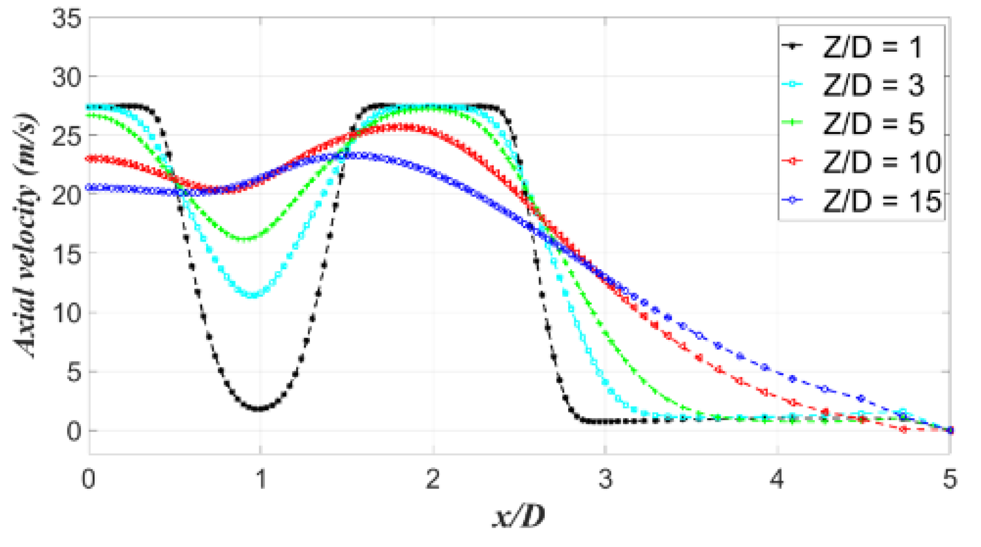
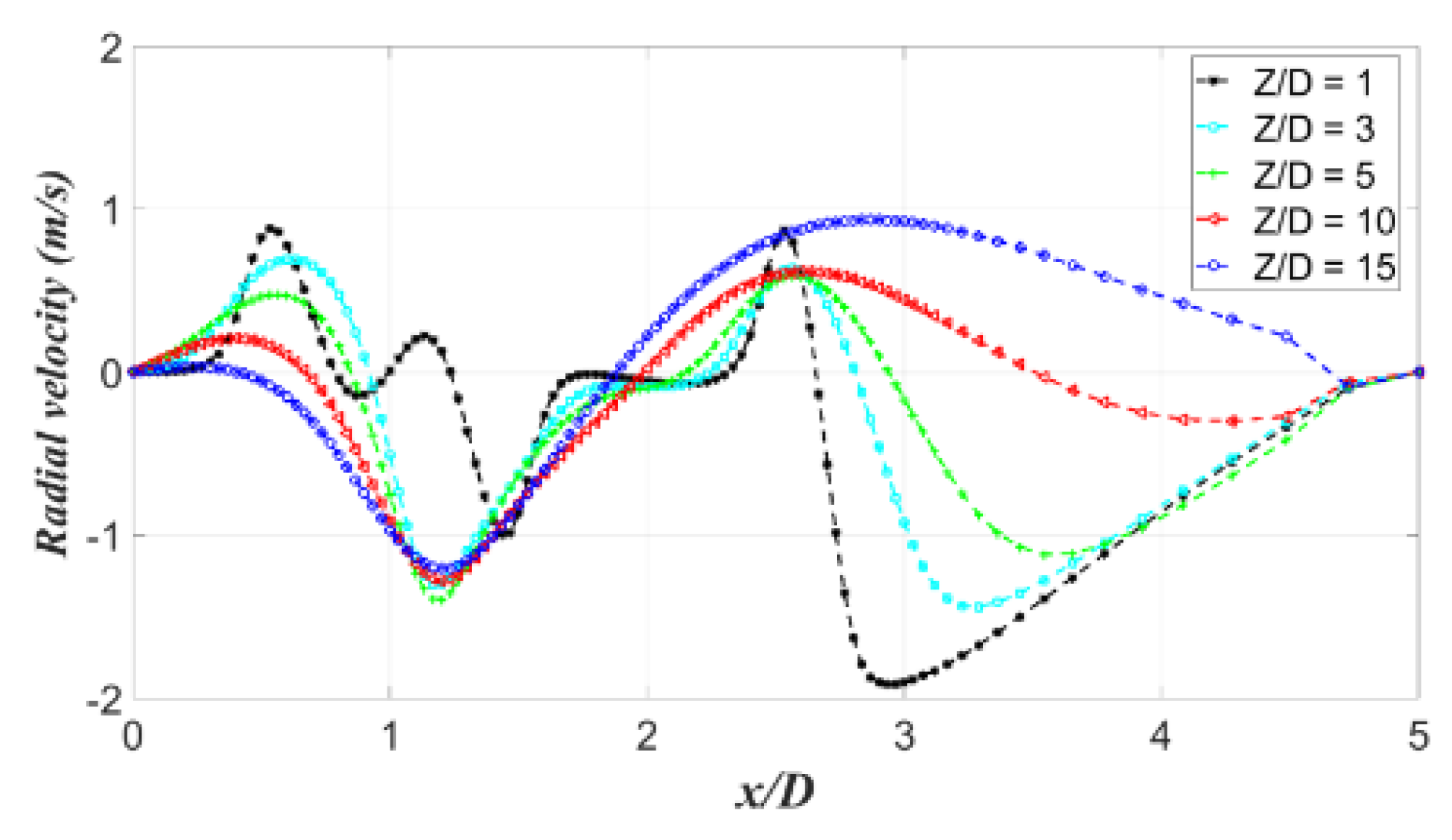
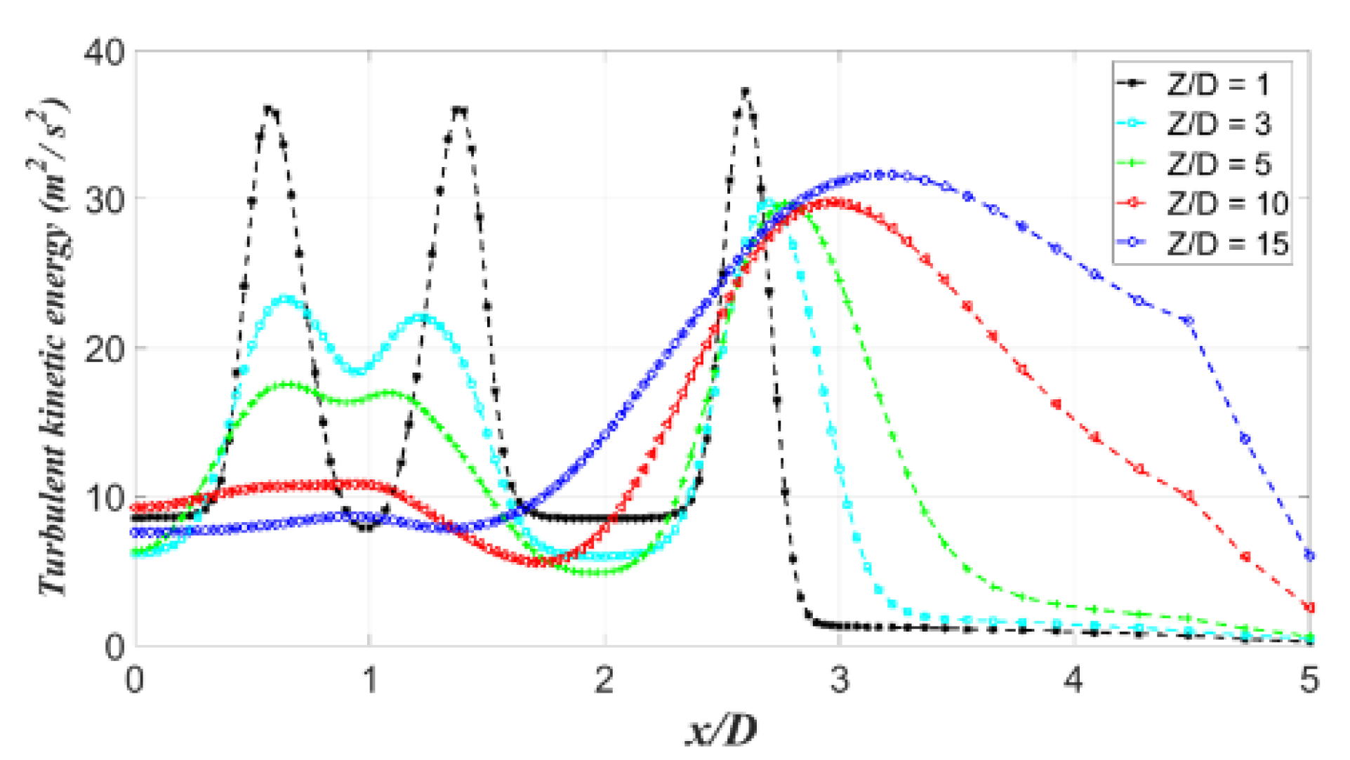
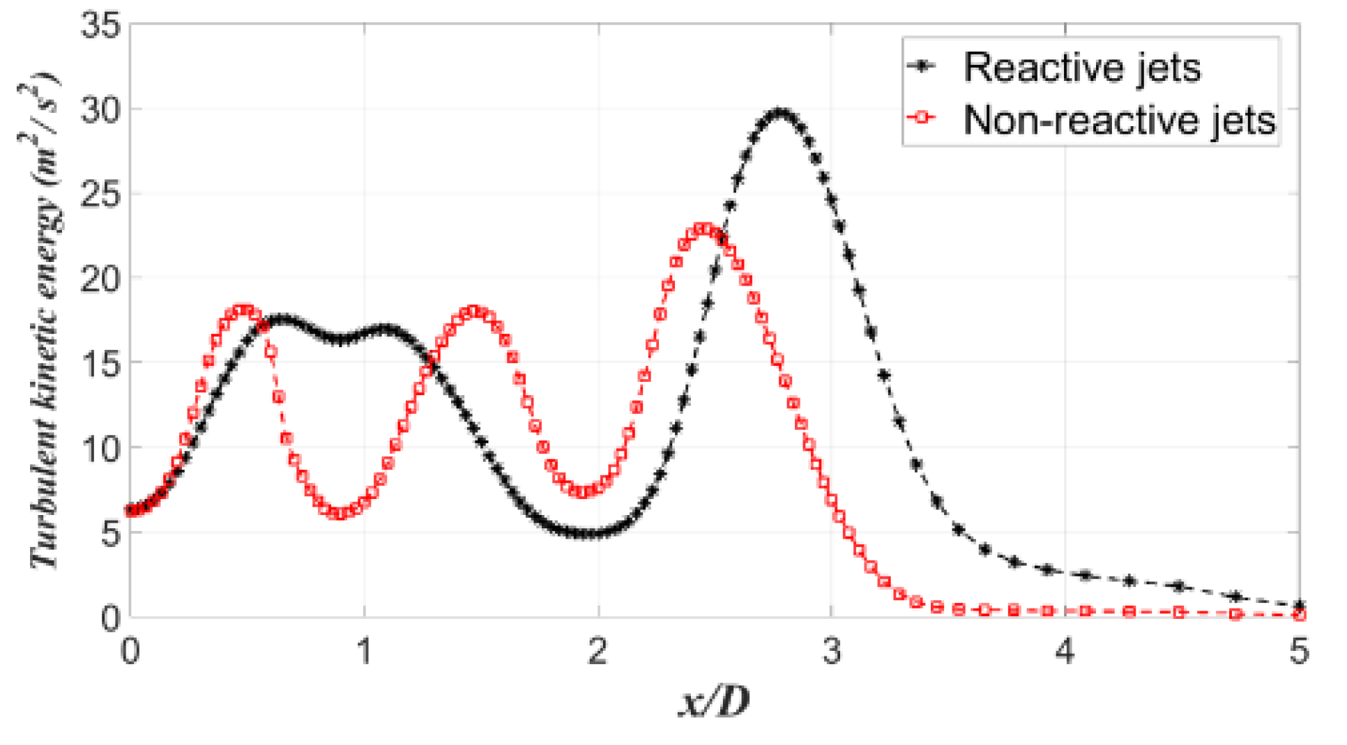
For reactive Oxy-methane flames, the axial velocity distributions, along the radial direction, are plotted in Figure 7. The velocity distribution is found to be more uniform in the far-field compared to far-field locations. Also, in the near-field, the fluctuations in both axial and radial velocities are significantly higher, which show a better mixing (Figure 8). This result is further confirmed from the turbulent kinetic energy distribution plot (Figure 9), where a higher turbulent kinetic energy at the mixing layer clearly reveals an efficient mixing.
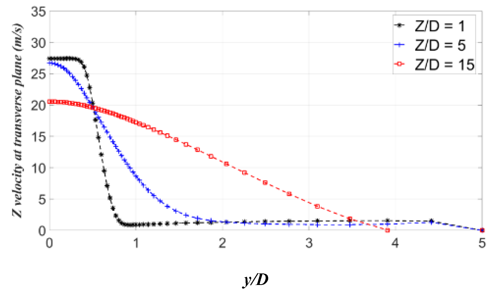
The axial velocity variation in the plane perpendicular to the centerline plane of the central jet is shown in Figure 10. In the near-field, the velocity profile remains unchanged, which is obviously due to the formation of potential core. However, in mid- and far-field locations, the axial velocity drops considerably and the profile becomes nearly self-similar.
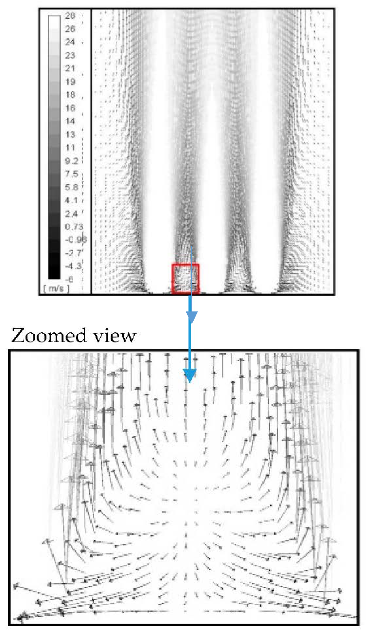
The axial and radial velocity contours in the centerline plane of the Oxy-methane jets are shown in Figure 11 and Figure 12, respectively. Interestingly, the central jet methane diffuses at a faster rate than the lateral oxygen jets, which may be because of the lower momentum of methane jet due to its relatively small density. Interestingly, the oxygen jets deflect towards each other after a certain downstream distance. This deflection may be due to the suction effects created by mass entrainment of every individual jet. Essentially, the entrainment of surrounding fluid inside the jet creates a low-pressure zone between the neighboring jets, which tilt them towards each other. The radial velocity contours show the formation of asymmetric vortices in the vicinity of the exit plane, which in fact help in promoting mixing. In addition, the shedding of mixing promoting counter-rotating vortices in the sub-atmospheric region (between the jets) is also observed in the radial velocity contours (Figure 13).

3.2. Centerline Velocity Decay (without Combustion)

A comparison between the velocity distributions and turbulence levels of Oxy-methane flames with the Oxy-methane cold jets are discussed in Figure 14a,b.
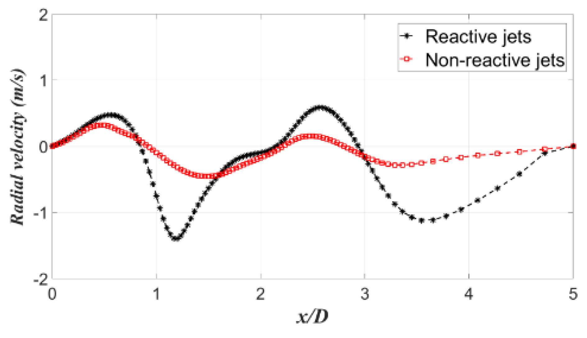
For reactive jets, the centerline velocity decay is more than the non-reactive jets due to the heat released from the combustion of reactive jets that spreads the jet further and hence reduces the velocity. The fluctuations in radial velocity distribution and turbulent kinetic energy distribution are also higher for non-reactive jets which clearly reflect an augmented mixing (Figure 15 and Figure 16).

3.3. Centerline Velocity Decay at Different Jet Inlet Velocity

The centerline velocity decay of Oxy-methane flames is plotted for both high and low jet velocities corresponding to 54 m/s and 27 m/s, respectively. The radial distribution of axial velocity is shown in Figure 17. Since the momentum deficit essentially resists the mixing, the velocity distribution is found to be more uniform at lower jet velocity.
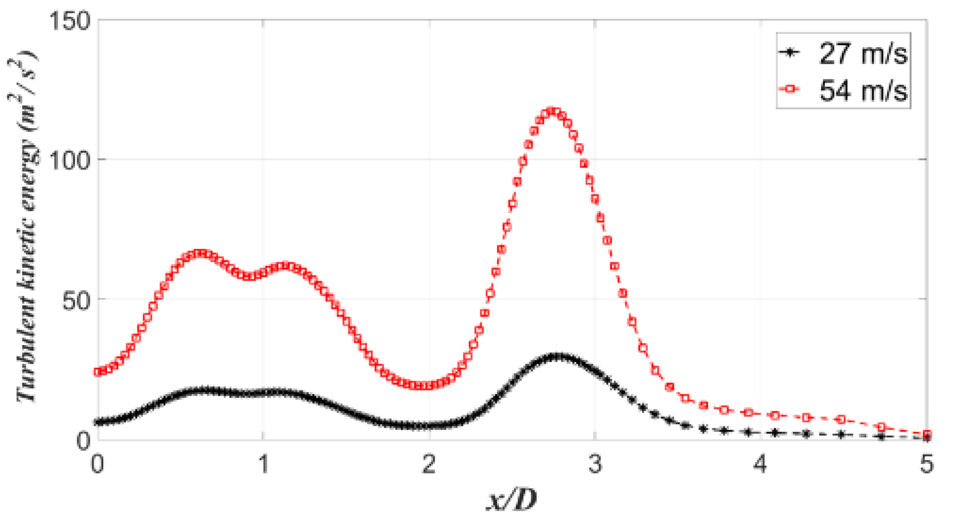
The fluctuations in radial velocity are higher at higher flow speeds due to large velocity gradients at the jet boundary (Figure 18). The more fluctuations in radial velocity indeed yield the higher turbulent kinetic energy (Figure 19). Also, the turbulence level is found to be higher between the jet boundary and its surroundings.

3.4. Centerline Velocity Decay at Different Jet Inlet Temperature

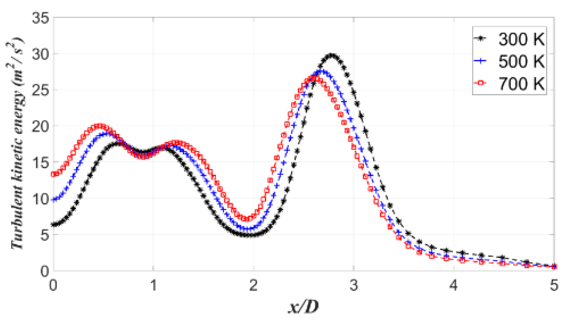
For the jet velocity of 27 m/s at the inlet, the centerline velocity decay at different inlet temperatures is shown in Figure 20a,b. Figures reveal an accelerated velocity decay at higher inlet temperatures and are more prominent in far-fields (z/D = 15). Further, an increase in the inlet temperature of reactant jets leads to a decrease in inlet density and reduces the jet momentum, thereby, causing a faster jet decay. The radial velocity and the turbulent kinetic energy distributions, shown in Figure 21 and Figure 22, show that an increase in inlet temperature leads to a decrease in radial velocity and suppresses the fluctuations in turbulent kinetic energy.

4. Conclusions

In this study, the inline configurations of three separated non-reactive Oxy-methane jets and non-premixed Oxy-methane flames are computationally investigated. Governing equations were solved using RANS with k-epsilon turbulence model. The density of the reactants is found to be a vital parameter in jet mixing; lower the density higher the jet decay. From the velocity contours and the vector plots in the centerline plane, formation of counter-rotating vortices in the sub-atmospheric region between the jets can be observed. Combustion greatly affects the centerline velocity decay; the decay is found to be more for non-reactive jets compared to reactive jets. Moreover, an increase in the inlet temperature leads to a decrease in inlet density and thus reduces the momentum of the jet, causing a faster decay. A higher inlet temperature of the reactants appears to be advantageous in establishing a stable flame.
An increase in flow speed increases the flow momentum, however, it delays the confluence of jets to further downstream. Therefore, the jets retain their characteristics with higher fluctuations and in turn destabilize the flame.
The present investigation describes flame stability in terms of velocity distribution at different initial conditions that would help in designing a stable Oxy-fuel burner. However, the numerical analysis was more focused on studying the aerodynamics of both hot and cold jets. Therefore, to have an accurate prediction of the species concentrations and the pollutant emissions, a further investigation that utilizes a more detailed chemical reaction mechanism and an adequate model for turbulence chemistry interaction should be carried out.

Author Contributions

All the authors have contributed their efforts to complete the paper. T.J. conducted numerical simulation and analyzed the results. M.K. supervised the work and reviewed the manuscript. D.D. wrote the first draft and edited the manuscript. V.M. co-wrote the first draft. M.U. supervised the numerical study and edited the manuscript. All authors have read and agreed to the published version of the manuscript.

Funding

This research received no external funding.

Acknowledgments

The authors acknowledge the Indian Institute Technology, Kharagpur for providing computational facilities to perform the numerical simulation.

Conflicts of Interest

The authors declare no conflict of interest.

Notations

DDiameter of the inlet for both jet
JMass diffusion flux
kTurbulent kinetic energy
rRadial direction
SSource term
vAxial velocity
xRadial direction
yTransverse direction
zFreestream flow direction
ɛTurbulence dissipation rate
ΦFlow properties
ΓTransport property
ρFluid density
µtTurbulent viscosity

References

  1. Liu, Y.; Deb, D.; Tao, G. Modeling and multivariable adaptive control of aircraft with synthetic jet actuators. In Proceedings of the 2008 7th World Congress on Intelligent Control and Automation, Chongqing, China, 25–27 June 2008; pp. 2192–2199. [Google Scholar]
  2. Semerjian, H.; Vranos, A. NOx formation in premixed turbulent flames. Symp. (International) Combust. 1977, 16, 169–179. [Google Scholar] [CrossRef]
  3. Tuncer, O.; Acharya, S.; Uhm, J. Dynamics, NOx and flashback characteristics of confined premixed hydrogen-enriched methane flames. Int. J. Hydrogen Energy 2009, 34, 496–506. [Google Scholar] [CrossRef]
  4. Gauntner, J.W.; Livingood, J.N.B.; Hrycak, P. Survey of Literature on Flow Characteristics of a Single Turbulent Jet Impinging on a Flat Plate; NASA Technical Note; NASA: Washington, DC, USA, 1970.
  5. Srinivasan, R.; Berenfeld, A.; Mongia, H.C. Multiple Jets in a Cross Flow; CR-168031; NASA: Washington, DC, USA, 1982.
  6. Holdeman, J.D. Mixing of multiple jets with a confined subsonic cross flow. Prog. Energy Corabust. Sci. 1993, 19, 31–70. [Google Scholar] [CrossRef] [Green Version]
  7. Holdeman, J.D.; Liscinsky, D.S.; Oechsle, V.L.; Samuelsen, G.S.; Smith, C.E. Mixing of Multiple Jets with a Confined Subsonic Crossflow: Part I—Cylindrical Duct. J. Eng. Gas Turbines Power 1997, 119, 852–862. [Google Scholar] [CrossRef]
  8. Holdeman, J.D.; Liscinsky, D.S.; Bain, D.B. Mixing of Multiple Jets With a Confined Subsonic Crossflow: Part II—Opposed Rows of Orifices in Rectangular Ducts. J. Eng. Gas Turbines Power 1999, 121, 551–562. [Google Scholar] [CrossRef]
  9. Panchapakesan, N.R.; Lumley, J.L. Turbulence measurements in axisymmetric jets of air and helium, Part 1, Air jet. J. Fluid Mech. 1993, 246, 197–223. [Google Scholar] [CrossRef]
  10. Panchapakesan, N.R.; Lumley, J.L. Turbulence measurements in axisymmetric jets of air and helium, Part 2, Helium jet. J. Fluid Mech. 1993, 246, 225–247. [Google Scholar] [CrossRef]
  11. Gazzah, M.H.; Sassi, M.; Brahim, S.; Gökalp, I. Numerical simulation of variable density subsonic turbulent jets by using the k–ε model. Int. J. Therm. Sci. 2002, 41, 51–62. [Google Scholar] [CrossRef]
  12. Thring, M.W.; Newby, M.P. Combustion length of enclosed turbulent jet flames. In Symposium (International) on Combustion; Elsevier: Amsterdam, The Netherlands, 1953; pp. 789–796. [Google Scholar]
  13. Clemens, N.; Paul, P. Effects of heat release on the near field flow structure of hydrogen jet diffusion flames. Combust. Flame 1995, 102, 271–284. [Google Scholar] [CrossRef]
  14. Rehm, J.; Clemens, N. The large-scale turbulent structure of nonpremixed planar jet flames. Combust. Flame 1999, 116, 615–626. [Google Scholar] [CrossRef]
  15. Kang, Y.-H.; Wang, Q.-H.; Lu, X.-F.; Ji, X.-Y.; Miao, S.-S.; Wang, H.; Guo, Q.; He, H.-H.; Xu, J. Experimental and theoretical study on the flow, mixing, and combustion characteristics of dimethyl ether, methane, and LPG jet diffusion flames. Fuel Process. Technol. 2015, 129, 98–112. [Google Scholar] [CrossRef]
  16. Bonelli, F.; Viggiano, A.; Magi, V. How does a high density ratio affect the near- and intermediate-field of high-Re hydrogen jets? Int. J. Hydrogen Energy 2016, 41, 15007–15025. [Google Scholar] [CrossRef]
  17. Raghunathan, S.; Reid, I.M. A study of multiple jets. AIAA J. 1981, 19, 124–127. [Google Scholar] [CrossRef]
  18. Leite, A.; Ferreira, M.; Carvalho, J. An investigation of multiple jet acetylene flames. Int. Commun. Heat Mass Transf. 1996, 23, 959–970. [Google Scholar] [CrossRef]
  19. Menon, R.; Gollahalli, S.R. Combustion Characteristics of Interacting Multiple Jets in Cross Flow. Combust. Sci. Technol. 1988, 60, 375–389. [Google Scholar] [CrossRef]
  20. Li, X.; Li, J.; Nakamura, H.; Tezuka, T.; Susumu, H.; Maruta, K. Study on flame responses and ignition characteristics of CH4/O2/CO2 mixture in a micro flow reactor with a controlled temperature profile. Appl. Therm. Eng. 2015, 2, 360–367. [Google Scholar] [CrossRef]
  21. Sautet, J.; Salentey, L.; DiTaranto, M.; Samaniego, J. Length of Natural Gas-Oxygen Non-Premixed Flames. Combust. Sci. Technol. 2001, 166, 131–150. [Google Scholar] [CrossRef]
  22. Sautet, J.-C.; Boushaki, T.; Salentey, L.; Labegorre, B. OXY-COMBUSTION PROPERTIES OF INTERACTING SEPARATED JETS. Combust. Sci. Technol. 2006, 178, 2075–2096. [Google Scholar] [CrossRef]
  23. Deb, D.; Tao, G.; Burkholder, J. An Adaptive Inverse Compensation Scheme for Signal-Dependent Actuator Nonlinearities. In Proceedings of the 2007 46th IEEE Conference on Decision and Control, New Orleans, LA, USA, 12–14 December 2007. [Google Scholar]
  24. Deb, D.; Tao, G.; Burkholder, J. Adaptive Approximation Based Compensation of Synthetic Jet Actuator Nonlinearities for Aircraft Control. In Proceedings of the 2007 AIAA Guidance, Navigation and Control Conference, Paper AIAA-2007-6523, Hilton Head, SC, USA, 20–23 August 2007. [Google Scholar]
  25. Deb, D.; Tao, G.; Burkholder, J.; Smith, D. An Adaptive Inverse Control Scheme for Synthetic Jet Actuator Arrays; Infotech@Aerospace: San Juan, PR, USA, 2005; p. 7170. [Google Scholar]
  26. Boushaki, T.; Mergheni, M.; Sautet, J.-C.; Labegorre, B. Effects of inclined jets on turbulent oxy-flame characteristics in a triple jet burner. Exp. Therm. Fluid Sci. 2008, 32, 1363–1370. [Google Scholar] [CrossRef]
  27. Boushaki, T.; Sautet, J.-C. Characteristics of flow from an oxy-fuel burner with separated jets: Influence of jet injection angle. Exp. Fluids 2009, 48, 1095–1108. [Google Scholar] [CrossRef]
  28. Boushaki, T.; Guessasma, S.; Sautet, J.-C. Predictive analysis of combined burner parameter effects on oxy-fuel flames. Appl. Therm. Eng. 2011, 31, 202–212. [Google Scholar] [CrossRef] [Green Version]
  29. Hidouri, A.; Yahya, N.; Boushaki, T.; Sadiki, A.; Sautet, J.-C. Numerical and experimental investigation of turbulent three separated jets. Appl. Therm. Eng. 2016, 104, 153–161. [Google Scholar] [CrossRef]
  30. Mergheni, M.; Boushaki, T.; Sautet, J.-C.; Ben Nasrallah, S. Numerical study of oxy-flame characteristics in a burner with three separated jets. Appl. Therm. Eng. 2017, 111, 1–7. [Google Scholar] [CrossRef]
  31. Yan, S.; Tang, G.; Chenn, Q.; Zhou, C.Q.; Guo, X. Computational Fluid Dynamics Modeling of Combustion Characteristics of a CH4/O2 Combustor in a Copper Anode Furnace. ACS Omega 2019, 4, 12449–12458. [Google Scholar] [CrossRef] [PubMed] [Green Version]
  32. Pope, S.B. An explanation of round jet/ plane jet anomaly. AIAA J. 1978, 16, 279–281. [Google Scholar] [CrossRef]
  33. Brahim, M.M.B.; Mergheni, M.A.; Khedher, N.B.; Ben, S.N.; Sautet, J.C. Numerical study of hydrogen enrichment effects in oxy-flame turbulent of three separated jets. Appl. Therm. Eng. 2017, 113, 490–498. [Google Scholar] [CrossRef]
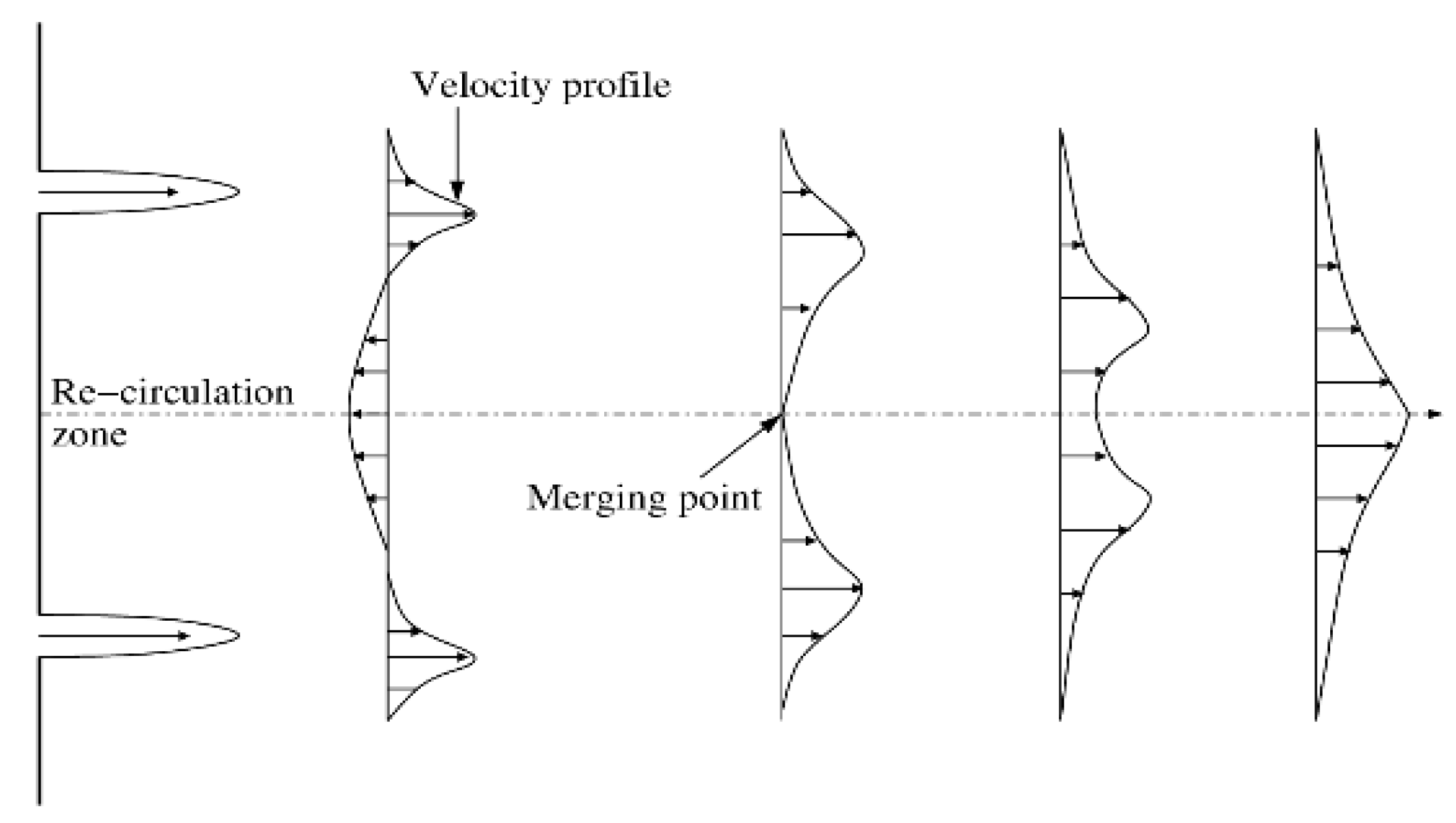
Figure 1. Centerline velocity distribution in multiple jets.
Processes 08 00429 g001
Figure 2. Generation of vortices at different planes.
Processes 08 00429 g002
Figure 3. Flow domain, and numerical domain.
Processes 08 00429 g003
Figure 4. Grid sensitivity test.
Processes 08 00429 g004
Figure 5. Validation of axial velocity variation in radial direction.
Processes 08 00429 g005
Figure 6. Radial velocity distribution for non-reactive oxy methane jets (Z/D = 3).
Processes 08 00429 g006
Figure 7. Axial velocity variation in radial direction at different streamwise locations.
Processes 08 00429 g007
Figure 8. Radial velocity distributions at different streamwise locations.
Processes 08 00429 g008
Figure 9. Turbulent kinetic energy distributions of different streamwise locations.
Processes 08 00429 g009
Figure 10. Axial velocity variation perpendicular to centerline planes at different streamwise locations.
Processes 08 00429 g010
Figure 11. Axial velocity contours in the centerline plane.
Processes 08 00429 g011
Figure 12. Radial velocity contours in the centerline plane.
Processes 08 00429 g012
Figure 13. Radial velocity contours in the centerline plane.
Processes 08 00429 g013
Figure 14. Axial velocity distribution in radial direction.
Processes 08 00429 g014
Figure 15. Radial velocity distributions with and without combustion effects (z/D = 5).
Processes 08 00429 g015
Figure 16. Turbulent kinetic energy distributions of reactive and non-reactive jets (z/D = 5).
Processes 08 00429 g016
Figure 17. Axial velocity distributions at varied jet inlet velocities (z/D = 5).
Processes 08 00429 g017
Figure 18. Radial velocity distributions at varied jet inlet velocities (z/D = 5).
Processes 08 00429 g018
Figure 19. Turbulent kinetic energy distributions at different jet inlet velocities (z/D = 5).
Processes 08 00429 g019
Figure 20. Axial velocity distributions at varied inlet temperatures.
Processes 08 00429 g020
Figure 21. Radial velocity distributions at varied inlet temperatures (z/D = 5).
Processes 08 00429 g021
Figure 22. Turbulent kinetic energy distributions at varied inlet temperatures (z/D = 5).
Processes 08 00429 g022
Table 1. Boundary conditions.
Volume-based Oxy-fuel ratio at stoichiometric composition2
WallsNo-slip condition, zero heat flux
Oxygen gas density1.331 Kg/m3
Methane gas density0.724 Kg/m3
Oxygen jet mass fraction at the inlet1
Methane jet mass fraction at the inlet0.995
Oxygen jet velocity at the inlet27.13 m/s, and 54 m/s
Methane jet velocity at the inlet27.13 m/s, and 54 m/s
Pressure at the outletZero gauge pressure
Turbulent intensity at the inlet10%
Reynolds number for oxygen jets12,272 and 24,426
Reynolds number for Methane jets12,272 and 24,426