Forward Osmosis: A Critical Review

 ,
,
Abstract
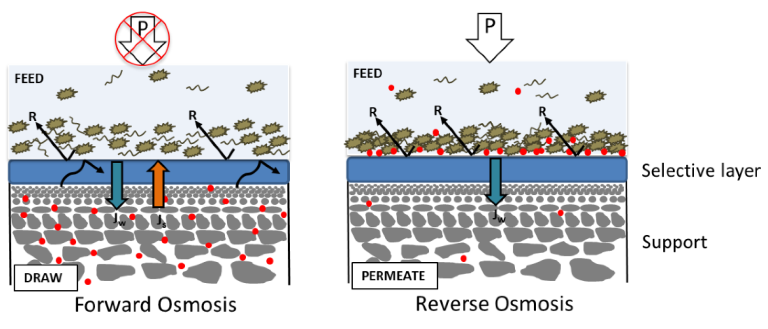
1. Introduction
1.1. Advantages of Forward Osmosis
1.2. Disadvantages of Forward Osmosis
1.3. Applications of Forward Osmosis
1.3.1. Wastewater Treatment
1.3.2. Desalination
1.3.3. Food-Related Applications
1.3.4. Specific Contaminants Removal
2. Challenges
2.1. Draw Solution
2.2. FO Membrane
- Have at least a water permeability of >1 L m−2 h−1 bar−1;
- Lowering the structural parameter of the support as much as possible;
- Increasing the selective layer’s rejection of the draw solute to maintain the osmotic pressure difference [17].
2.2.1. Selective Layer
Thin-Film Composites Membranes by Interfacial Polymerization
Layer-by-Layer Assembly
Other Preparation Methods
2.2.2. Support
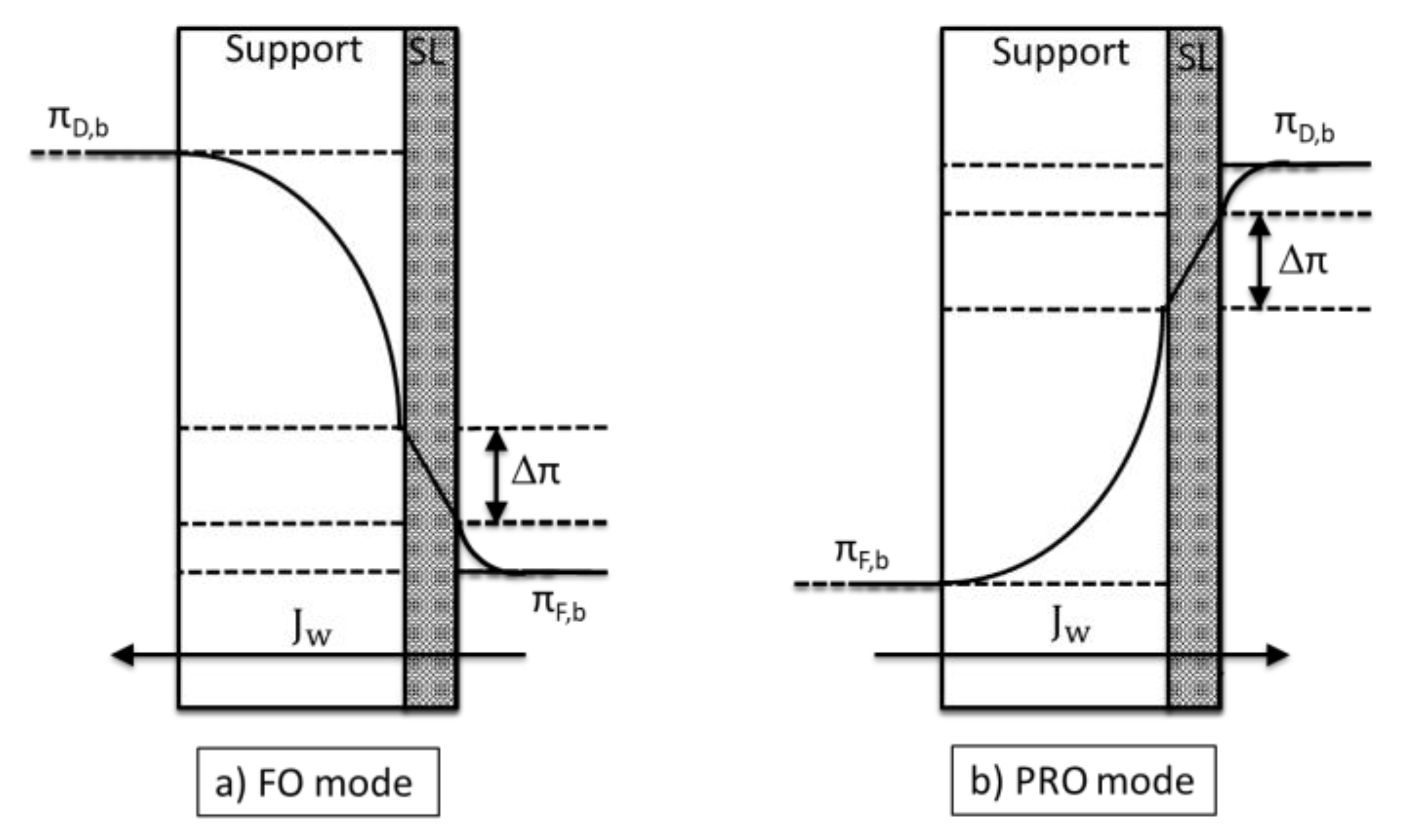
Internal Concentration Polarization
- The convective flow pushes the feed solute into the support.
Structural Parameter (S)
Impact of Wall Thickness on S Relative to The Influence of Tortuosity and Porosity
3. Concluding Remarks
Author Contributions
Funding
Conflicts of Interest
References
- McGinnis, R.I.; Elimelech, M. Global Challenges in Energy and Water Supply: The Promise of Engineered Osmosis. Environ. Sci. Technol 2008, 42, 8625–8629. [Google Scholar] [CrossRef] [PubMed]
- Shannon, M.A.; Bohn, P.W.; Elimelech, M.; Georgiadis, J.G.; Marĩas, B.J.; Mayes, A.M. Science and technology for water purification in the coming decades. Nature 2008, 452, 301–310. [Google Scholar] [CrossRef] [PubMed]
- Elimelech, M.; Phillip, W.A. The Future of Seawater Desalination: Energy, Technology, and the Environment. Science 2011, 333, 712–717. [Google Scholar] [CrossRef] [PubMed]
- Zhao, S.; Zou, L.; Tang, C.Y.; Mulcahy, D. Recent developments in forward osmosis: Opportunities and challenges. J. Membr. Sci. 2012, 396, 1–21. [Google Scholar] [CrossRef]
- Nurizzo, C.; Antonelli, M.; Profaizer, M.; Romele, L. By-products in surface and reclaimed water disinfected with various agents. Desalination 2005, 176, 241–253. [Google Scholar] [CrossRef]
- Cath, T.Y.; Hancock, N.T.; Lundin, C.D.; Hoppe-jones, C.; Drewes, J.E. A multi-barrier osmotic dilution process for simultaneous desalination and purification of impaired water. J. Membr. Sci. 2010, 362, 417–426. [Google Scholar] [CrossRef]
- Fritzmann, C.; Löwenberg, J.; Wintgens, T.; Melin, T. State-of-the-art of reverse osmosis desalination. Desalination 2007, 216, 1–76. [Google Scholar] [CrossRef]
- Lee, K.P.; Arnot, T.C.; Mattia, D. A review of reverse osmosis membrane materials for desalination—Development to date and future potential. J. Membr. Sci. 2011, 370, 1–22. [Google Scholar] [CrossRef]
- Lin, S.; Elimelech, M. Staged reverse osmosis operation: Configurations, energy efficiency, and application potential. Desalination 2015, 366, 9–14. [Google Scholar] [CrossRef]
- Scott, C.A.; Pierce, S.A.; Pasqualetti, M.J.; Jones, A.L.; Montz, B.E.; Hoover, J.H. Policy and institutional dimensions of the water–energy nexus. Energy Policy 2011, 39, 6622–6630. [Google Scholar] [CrossRef]
- King, C.W.; Webber, M.E. Water intensity of transportation. Environ. Sci. Technol. 2008, 42, 7866–7872. [Google Scholar] [CrossRef] [PubMed]
- Nasr, P.; Sewilam, H. Forward osmosis: An alternative sustainable technology and potential applications in water industry. Clean Technol. Environ. Policy 2015, 17, 2079–2090. [Google Scholar] [CrossRef]
- Lutchmiah, K.; Verliefde, A.R.D.; Roest, K.; Rietveld, L.C.; Cornelissen, E.R. Forward osmosis for application in wastewater treatment: A review. Water Res. 2014, 58, 179–197. [Google Scholar] [CrossRef]
- Cath, T.Y.; Childress, A.E.; Elimelech, M. Forward osmosis: Principles, applications, and recent developments. J. Membr. Sci. 2006, 281, 70–87. [Google Scholar] [CrossRef]
- Chung, T.-S.; Zhang, S.; Wang, K.Y.; Su, J.; Ling, M.M. Forward osmosis processes: Yesterday, today and tomorrow. Desalination 2012, 287, 78–81. [Google Scholar] [CrossRef]
- Bajraktari, N.; Hélix-nielsen, C.; Madsen, H.T. Pressure retarded osmosis from hypersaline sources—A review. Desalination 2017, 413, 65–85. [Google Scholar] [CrossRef]
- Shaffer, D.L.; Werber, J.R.; Jaramillo, H.; Lin, S.; Elimelech, M. Forward osmosis: Where are we now? Desalination 2015, 356, 271–284. [Google Scholar] [CrossRef]
- Eyvaz, M.; Arslan, S.; İmer, D.; Yuksel, E.; Koyuncu, I. Forward Osmosis Membranes—A Review: Part I; IntechOpen: London, UK, 2018; ISBN 978-953-51-3921-8. [Google Scholar]
- Wang, Y.; Goh, K.; Li, X.; Setiawan, L.; Wang, R. Membranes and processes for forward osmosis-based desalination: Recent advances and future prospects. Desalination 2018, 434, 81–99. [Google Scholar] [CrossRef]
- Suwaileh, W.A.; Johnson, D.J.; Sarp, S.; Hilal, N. Advances in forward osmosis membranes: Altering the sub-layer structure via recent fabrication and chemical modification approaches. Desalination 2018, 436, 176–201. [Google Scholar] [CrossRef]
- Lee, D.-J.; Hsieh, M.-H. Forward osmosis membrane processes for wastewater bioremediation: Research needs. Bioresour. Technol. 2019, 290, 121795. [Google Scholar] [CrossRef]
- Chia, W.Y.; Khoo, K.S.; Chia, S.R.; Chew, K.W.; Yew, G.Y.; Ho, Y.-C.; Show, P.L.; Chen, W.-H. Factors Affecting the Performance of Membrane Osmotic Processes for Bioenergy Development. Energies 2020, 13, 481. [Google Scholar] [CrossRef]
- Manickam, S.S.; McCutcheon, J.R. Understanding mass transfer through asymmetric membranes during forward osmosis: A historical perspective and critical review on measuring structural parameter with semi-empirical models and characterization approaches. Desalination 2017, 421, 110–126. [Google Scholar] [CrossRef]
- Kim, B.; Gwak, G.; Hong, S. Review on methodology for determining forward osmosis (FO) membrane characteristics: Water permeability (A), solute permeability (B), and structural parameter (S). Desalination 2017, 422, 5–16. [Google Scholar] [CrossRef]
- Ang, W.L.; Mohammad, A.W.; Johnson, D.; Hilal, N. Unlocking the application potential of forward osmosis through integrated/hybrid process. Sci. Total Environ. 2020, 706, 136047. [Google Scholar] [CrossRef] [PubMed]
- Li, L.; Shi, W.; Yu, S. Research on Forward Osmosis Membrane Technology Still Needs Improvement in Water Recovery and Wastewater Treatment. Water 2019, 12, 107. [Google Scholar] [CrossRef]
- Chaoui, I.; Abderafi, S.; Vaudreuil, S.; Bounahmidi, T. Water desalination by forward osmosis: Draw solutes and recovery methods—Review. Environ. Technol. Rev. 2019, 8, 25–46. [Google Scholar] [CrossRef]
- Long, Q.; Jia, Y.; Li, J.; Yang, J.; Liu, F.; Zheng, J.; Yu, B. Recent Advance on Draw Solutes Development in Forward Osmosis. Processes 2018, 6, 165. [Google Scholar] [CrossRef]
- Johnson, D.J.; Suwaileh, W.A.; Mohammed, A.W.; Hilal, N. Osmotic’s potential: An overview of draw solutes for forward osmosis. Desalination 2018, 434, 100–120. [Google Scholar] [CrossRef]
- Sreedhar, I.; Khaitan, S.; Gupta, R.; Reddy, B.M.; Venugopal, A. An odyssey of process and engineering trends in forward osmosis. Environ. Sci. Water Res. Technol. 2018, 4, 129–168. [Google Scholar] [CrossRef]
- Dutta, S.; Nath, K. Prospect of ionic liquids and deep eutectic solvents as new generation draw solution in forward osmosis process. J. Water Process Eng. 2018, 21, 163–176. [Google Scholar] [CrossRef]
- Ansari, A.J.; Hai, F.I.; Price, W.E.; Drewes, J.E.; Nghiem, L.D. Forward osmosis as a platform for resource recovery from municipal wastewater—A critical assessment of the literature. J. Membr. Sci. 2017, 529, 195–206. [Google Scholar] [CrossRef]
- Wibisono, Y.; Agung Nugroho, W.; Akbar Devianto, L.; Adi Sulianto, A.; Roil Bilad, M. Microalgae in Food-Energy-Water Nexus: A Review on Progress of Forward Osmosis Applications. Membranes 2019, 9, 166. [Google Scholar] [CrossRef] [PubMed]
- Ang, W.L.; Wahab Mohammad, A.; Johnson, D.; Hilal, N. Forward osmosis research trends in desalination and wastewater treatment: A review of research trends over the past decade. J. Water Process Eng. 2019, 31, 100886. [Google Scholar] [CrossRef]
- Goh, P.S.; Ismail, A.F.; Ng, B.C.; Abdullah, M.S. Recent Progresses of Forward Osmosis Membranes Formulation and Design for Wastewater Treatment. Water 2019, 11, 2043. [Google Scholar] [CrossRef]
- Das, P.; Singh, K.K.K.; Dutta, S. Insight into emerging applications of forward osmosis systems. J. Ind. Eng. Chem. 2019, 72, 1–17. [Google Scholar] [CrossRef]
- Ray, S.S.; Chen, S.-S.; Sangeetha, D.; Chang, H.-M.; Thanh, C.N.D.; Le, Q.H.; Ku, H.-M. Developments in forward osmosis and membrane distillation for desalination of waters. Environ. Chem. Lett. 2018, 16, 1247–1265. [Google Scholar] [CrossRef]
- Haupt, A.; Lerch, A. Forward Osmosis Application in Manufacturing Industries: A Short Review. Membranes 2018, 8, 47. [Google Scholar] [CrossRef]
- Xu, W.; Chen, Q.; Ge, Q. Recent advances in forward osmosis (FO) membrane: Chemical modifications on membranes for FO processes. Desalination 2017, 419, 101–116. [Google Scholar] [CrossRef]
- Li, L.; Liu, X.; Li, H. A review of forward osmosis membrane fouling: Types, research methods and future prospects. Environ. Technol. Rev. 2017, 6, 26–46. [Google Scholar] [CrossRef]
- Yadav, S.; Saleem, H.; Ibrar, I.; Naji, O.; Hawari, A.A.; Alanezi, A.A.; Zaidi, S.J.; Altaee, A.; Zhou, J. Recent developments in forward osmosis membranes using carbon-based nanomaterials. Desalination 2020, 482, 114375. [Google Scholar] [CrossRef]
- Lee, W.J.; Ng, Z.C.; Hubadillah, S.K.; Goh, P.S.; Lau, W.J.; Othman, M.H.D.; Ismail, A.F.; Hilal, N. Fouling mitigation in forward osmosis and membrane distillation for desalination. Desalination 2020, 480, 114338. [Google Scholar] [CrossRef]
- Firouzjaei, M.D.; Seyedpour, S.F.; Aktij, S.A.; Giagnorio, M.; Bazrafshan, N.; Mollahosseini, A.; Samadi, F.; Ahmadalipour, S.; Firouzjaei, F.D.; Esfahani, M.R.; et al. Recent advances in functionalized polymer membranes for biofouling control and mitigation in forward osmosis. J. Membr. Sci. 2020, 596, 117604. [Google Scholar] [CrossRef]
- Ly, Q.V.; Hu, Y.; Li, J.; Cho, J.; Hur, J. Characteristics and influencing factors of organic fouling in forward osmosis operation for wastewater applications: A comprehensive review. Environ. Int. 2019, 129, 164–184. [Google Scholar] [CrossRef] [PubMed]
- Ibrar, I.; Naji, O.; Sharif, A.; Malekizadeh, A.; Alhawari, A.; Alanezi, A.A.; Altaee, A. A Review of Fouling Mechanisms, Control Strategies and Real-Time Fouling Monitoring Techniques in Forward Osmosis. Water 2019, 11, 695. [Google Scholar] [CrossRef]
- Chun, Y.; Mulcahy, D.; Zou, L.; Kim, I.S. A short review of membrane fouling in forward osmosis processes. Membranes 2017, 7, 1–23. [Google Scholar] [CrossRef] [PubMed]
- Zou, S.; Qin, M.; He, Z. Tackle reverse solute flux in forward osmosis towards sustainable water recovery: Reduction and perspectives. Water Res. 2019, 149, 362–374. [Google Scholar] [CrossRef]
- Alejo, T.; Arruebo, M.; Carcelen, V.; Monsalvo, V.M.; Sebastian, V. Advances in draw solutes for forward osmosis: Hybrid organic-inorganic nanoparticles and conventional solutes. Chem. Eng. J. 2017, 309, 738–752. [Google Scholar] [CrossRef]
- Khan, J.A.; Shon, H.K.; Nghiem, L.D. From the Laboratory to Full-Scale Applications of Forward Osmosis: Research Challenges and Opportunities. Curr. Pollut. Rep. 2019, 5, 337–352. [Google Scholar] [CrossRef]
- Awad, A.M.; Jalab, R.; Minier-Matar, J.; Adham, S.; Nasser, M.S.; Judd, S.J. The status of forward osmosis technology implementation. Desalination 2019, 461, 10–21. [Google Scholar] [CrossRef]
- Kwan, S.E.; Bar-zeev, E.; Elimelech, M. Biofouling in forward osmosis and reverse osmosis: Measurements and mechanisms. J. Membr. Sci. 2015, 493, 703–708. [Google Scholar] [CrossRef]
- Xie, M.; Lee, J.; Nghiem, L.D.; Elimelech, M. Role of pressure in organic fouling in forward osmosis and reverse osmosis. J. Membr. Sci. 2015, 493, 748–754. [Google Scholar] [CrossRef]
- Lotfi, F.; Chekli, L.; Phuntsho, S.; Hong, S.; Choi, J.Y.; Shon, H.K. Understanding the possible underlying mechanisms for low fouling tendency of the forward osmosis and pressure assisted osmosis processes. Desalination 2017, 421, 89–98. [Google Scholar] [CrossRef]
- Yu, Y.; Lee, S.; Maeng, S.K. Forward osmosis membrane fouling and cleaning for wastewater reuse. J. Water Reuse Desalin. 2016, 7, 111–120. [Google Scholar] [CrossRef]
- Zhang, X.; Tian, J.; Gao, S.; Zhang, Z.; Cui, F.; Tang, C.Y. In situ surface modification of thin film composite forward osmosis membranes with sulfonated poly (arylene ether sulfone) for anti-fouling in emulsified oil/water separation. J. Membr. Sci. 2017, 527, 26–34. [Google Scholar] [CrossRef]
- Jin, L.; Wang, Z.; Zheng, S.; Mi, B. Polyamide-crosslinked graphene oxide membrane for forward osmosis. J. Membr. Sci. 2018, 545, 11–18. [Google Scholar] [CrossRef]
- Mi, B.; Elimelech, M. Chemical and physical aspects of organic fouling of forward osmosis membranes. J. Membr. Sci. 2008, 320, 292–302. [Google Scholar] [CrossRef]
- Mi, B.; Elimelech, M. Organic fouling of forward osmosis membranes: Fouling reversibility and cleaning without chemical reagents. J. Membr. Sci. 2010, 348, 337–345. [Google Scholar] [CrossRef]
- Achilli, A.; Cath, T.Y.; Marchand, E.A.; Childress, A.E. The forward osmosis membrane bioreactor: A low fouling alternative to MBR processes. Desalination 2009, 239, 10–21. [Google Scholar] [CrossRef]
- Lee, S.; Boo, C.; Elimelech, M.; Hong, S. Comparison of fouling behavior in forward osmosis (FO) and reverse osmosis (RO). J. Membr. Sci. 2010, 365, 34–39. [Google Scholar] [CrossRef]
- Mi, B.; Elimelech, M. Silica scaling and scaling reversibility in forward osmosis. DES 2013, 312, 75–81. [Google Scholar] [CrossRef]
- Kim, Y.; Elimelech, M.; Kyong, H.; Hong, S. Combined organic and colloidal fouling in forward osmosis: Fouling reversibility and the role of applied pressure. J. Membr. Sci. 2014, 460, 206–212. [Google Scholar] [CrossRef]
- Marshall, A.D.; Munro, P.A.; Trägårdh, G. Influence of permeate flux on fouling during the microfiltration of β-lactoglobulin solutions under cross-flow conditions. J. Membr. Sci. 1997, 130, 23–30. [Google Scholar] [CrossRef]
- Nguyen, T.; Kook, S.; Lee, C.; Field, R.W.; Kim, I.S. Critical flux-based membrane fouling control of forward osmosis: Behavior, sustainability, and reversibility. J. Membr. Sci. 2019, 570, 380–393. [Google Scholar] [CrossRef]
- Xie, M.; Nghiem, L.D.; Price, W.E.; Elimelech, M. Comparison of the removal of hydrophobic trace organic contaminants by forward osmosis and reverse osmosis. Water Res. 2012, 46, 2683–2692. [Google Scholar] [CrossRef] [PubMed]
- Liu, C.; Takagi, R.; Cheng, L.; Saeki, D.; Matsuyama, H. Enzyme-aided forward osmosis (E-FO) process to enhance removal of micropollutants from water resources. J. Membr. Sci. 2020, 593, 117399. [Google Scholar] [CrossRef]
- Chung, T.S.; Li, X.; Ong, R.C.; Ge, Q.; Wang, H.; Han, G. Emerging forward osmosis (FO) technologies and challenges ahead for clean water and clean energy applications. Curr. Opin. Chem. Eng. 2012, 1, 246–257. [Google Scholar] [CrossRef]
- Arsalan, F.; She, Q.; Fane, A.G.; Field, R.W. Exploring the differences between forward osmosis and reverse osmosis fouling. J. Membr. Sci. 2018, 565, 241–253. [Google Scholar]
- Zhang, J.; She, Q.; Chang, V.W.C.; Tang, C.Y.; Webster, R.D. Mining Nutrients (N, K, P) from Urban Source-Separated Urine by Forward Osmosis Dewatering. Environ. Sci. Technol. 2014, 48, 3386–3394. [Google Scholar] [CrossRef]
- Phuntsho, S.; Kyong, H.; Hong, S.; Lee, S.; Vigneswaran, S. A novel low energy fertilizer driven forward osmosis desalination for direct fertigation: Evaluating the performance of fertilizer draw solutions. J. Membr. Sci. 2011, 375, 172–181. [Google Scholar] [CrossRef]
- Mcgovern, R.K. On the potential of forward osmosis to energetically outperform reverse osmosis desalination. J. Membr. Sci. 2014, 469, 245–250. [Google Scholar] [CrossRef]
- Cai, Y.; Hu, X.M. A critical review on draw solutes development for forward osmosis. Desalination 2016, 391, 16–29. [Google Scholar] [CrossRef]
- Tang, C.Y.; She, Q.; Lay, W.C.L.; Wang, R.; Fane, A.G. Coupled effects of internal concentration polarization and fouling on flux behavior of forward osmosis membranes during humic acid filtration. J. Membr. Sci. 2010, 354, 123–133. [Google Scholar] [CrossRef]
- Qi, S.; Qiu, C.Q.; Zhao, Y.; Tang, C.Y. Double-skinned forward osmosis membranes based on layer-by-layer assembly-FO performance and fouling behavior. J. Membr. Sci. 2012, 405, 20–29. [Google Scholar] [CrossRef]
- Su, J.; Chung, T.S.; Helmer, B.J.; de Wit, J.S. Enhanced double-skinned FO membranes with inner dense layer for wastewater treatment and macromolecule recycle using Sucrose as draw solute. J. Membr. Sci. 2012, 396, 92–100. [Google Scholar] [CrossRef]
- McCutcheon, J.R.; Elimelech, M. Influence of concentrative and dilutive internal concentration polarization on flux behavior in forward osmosis. J. Membr. Sci. 2006, 284, 237–247. [Google Scholar] [CrossRef]
- Zhang, S.; Wang, K.Y.; Chung, T.S.; Chen, H.; Jean, Y.C.; Amy, G. Well-constructed cellulose acetate membranes for forward osmosis: Minimized internal concentration polarization with an ultra-thin selective layer. J. Membr. Sci. 2010, 360, 522–535. [Google Scholar] [CrossRef]
- Gao, Y.; Fang, Z.; Liang, P.; Huang, X. Direct concentration of municipal sewage by forward osmosis and membrane fouling behavior. Bioresour. Technol. 2018, 247, 730–735. [Google Scholar] [CrossRef]
- Blandin, G.; Verliefde, A.R.D.; Comas, J.; Rodriguez-Roda, I.; Le-Clech, P. Efficiently combining water reuse and desalination through forward osmosis-reverse osmosis (FO-RO) hybrids: A critical review. Membranes 2016, 6, 36. [Google Scholar] [CrossRef]
- Pan, S.F.; Dong, Y.; Zheng, Y.M.; Zhong, L.B.; Yuan, Z.H. Self-sustained hydrophilic nanofiber thin film composite forward osmosis membranes: Preparation, characterization and application for simulated antibiotic wastewater treatment. J. Membr. Sci. 2017, 523, 205–215. [Google Scholar] [CrossRef]
- Kravath, R.E.; Davis, J.A. Desalination of sea water by direct osmosis. Desalination 1975, 16, 151–155. [Google Scholar] [CrossRef]
- Zhao, S.; Zou, L.; Mulcahy, D. Brackish water desalination by a hybrid forward osmosis-nanofiltration system using divalent draw solute. Desalination 2012, 284, 175–181. [Google Scholar] [CrossRef]
- McCutcheon, J.R.; McGinnis, R.L.; Elimelech, M. Desalination by ammonia-carbon dioxide forward osmosis: Influence of draw and feed solution concentrations on process performance. J. Membr. Sci. 2006, 278, 114–123. [Google Scholar] [CrossRef]
- McCutcheon, J.R.; McGinnis, R.L.; Elimelech, M. A novel ammonia-carbon dioxide forward (direct) osmosis desalination process. Desalination 2005, 174, 1–11. [Google Scholar] [CrossRef]
- Rastogi, N.K. Opportunities and Challenges in Application of Forward Osmosis in Food Processing. Crit. Rev. Food Sci. Nutr. 2016, 56, 266–291. [Google Scholar] [CrossRef]
- Dova, M.I.; Petrotos, K.B.; Lazarides, H.N. On the direct osmotic concentration of liquid foods: Part II. Development of a generalized model. J. Food Eng. 2007, 78, 431–437. [Google Scholar] [CrossRef]
- Terefe, N.S.; Janakievski, F.; Glagovskaia, O.; De Silva, K.; Horne, M.; Stockmann, R. Forward Osmosis: A Novel Membrane Separation Technology of Relevance to Food and Related Industries; Elsevier: Amsterdam, The Netherlands, 2016; ISBN 9780081002988. [Google Scholar]
- Popper, K.; Camirand, W.M.; Nury, F.; Stanley, W.L. Stanley Dialyzer concentrates beverages. Food Eng. 1966, 38, 102–104. [Google Scholar]
- Chanukya, B.S.; Rastogi, N.K. A Comparison of Thermal Processing, Freeze Drying and Forward Osmosis for the Downstream Processing of Anthocyanin from Rose Petals. J. Food Process. Preserv. 2016, 40, 1289–1296. [Google Scholar] [CrossRef]
- Singh, N.; Petrinic, I.; Hélix-Nielsen, C.; Basu, S.; Balakrishnan, M. Concentrating molasses distillery wastewater using biomimetic forward osmosis (FO) membranes. Water Res. 2018, 130, 271–280. [Google Scholar] [CrossRef]
- Wang, Y.N.; Wang, R.; Li, W.; Tang, C.Y. Whey recovery using forward osmosis—Evaluating the factors limiting the flux performance. J. Membr. Sci. 2017, 533, 179–189. [Google Scholar] [CrossRef]
- Madhumala, M.; Moulik, S.; Sankarshana, T.; Sridhar, S. Forward-osmosis-aided concentration of fructose sugar through hydrophilized polyamide membrane: Molecular modeling and economic estimation. J. Appl. Polym. Sci. 2017, 134, 1–12. [Google Scholar] [CrossRef]
- Han, G.; Chan, S.S.; Chung, T.S. Forward Osmosis (FO) for Water Reclamation from Emulsified Oil/Water Solutions: Effects of Membrane and Emulsion Characteristics. ACS Sustain. Chem. Eng. 2016, 4, 5021–5032. [Google Scholar] [CrossRef]
- Chun, Y.; Kim, S.J.; Millar, G.J.; Mulcahy, D.; Kim, I.S.; Zou, L. Forward osmosis as a pre-treatment for treating coal seam gas associated water: Flux and fouling behaviour. Desalination 2017, 403, 144–152. [Google Scholar] [CrossRef]
- Liu, C.; Lei, X.; Wang, L.; Jia, J.; Liang, X.; Zhao, X.; Zhu, H. Investigation on the removal performances of heavy metal ions with the layer-by-layer assembled forward osmosis membranes. Chem. Eng. J. 2017, 327, 60–70. [Google Scholar] [CrossRef]
- You, S.; Lu, J.; Tang, C.Y.; Wang, X. Rejection of heavy metals in acidic wastewater by a novel thin-film inorganic forward osmosis membrane. Chem. Eng. J. 2017, 320, 532–538. [Google Scholar] [CrossRef]
- Vital, B.; Bartacek, J.; Ortega-Bravo, J.C.; Jeison, D. Treatment of acid mine drainage by forward osmosis: Heavy metal rejection and reverse flux of draw solution constituents. Chem. Eng. J. 2018, 332, 85–91. [Google Scholar] [CrossRef]
- Sivertsen, E.; Holt, T.; Thelin, W.; Brekke, G. Pressure retarded osmosis efficiency for different hollow fibre membrane module flow configurations. Desalination 2013, 312, 107–123. [Google Scholar] [CrossRef]
- Allegrezza, A.E.; Burchesky, R.D.; Götz, G.; Davis, R.B.; Coplan, M.J. Hollow fiber composite reverse osmosis membrane. Desalination 1977, 20, 87–94. [Google Scholar] [CrossRef]
- Li, S.G.; Koops, G.H.; Mulder, M.H.V.; van den Boomgaard, T.; Smolders, C.A. Wet spinning of integrally skinned hollow fiber membranes by a modified dual-bath coagulation method using a triple orifice spinneret. J. Membr. Sci. 1994, 94, 329–340. [Google Scholar] [CrossRef]
- Hey, T.; Bajraktari, N.; Davidsson, Å.; Vogel, J.; Madsen, H.T.; Hélix-Nielsen, C.; Jansen, J.L.C.; Jönsson, K. Evaluation of direct membrane filtration and direct forward osmosis as concepts for compact and energy-positive municipal wastewater treatment. Environ. Technol. 2018, 39, 264–276. [Google Scholar] [CrossRef]
- Sant’Anna, V.; Marczak, L.D.F.; Tessaro, I.C. Membrane concentration of liquid foods by forward osmosis: Process and quality view. J. Food Eng. 2012, 111, 483–489. [Google Scholar] [CrossRef]
- Barros, A.I.R.N.A.; Nunes, F.M.; Gonçalves, B.; Bennett, R.N.; Silva, A.P. Effect of cooking on total vitamin C contents and antioxidant activity of sweet chestnuts (Castanea sativa Mill.). Food Chem. 2011, 128, 165–172. [Google Scholar] [CrossRef] [PubMed]
- Mohammad, A.W.; Ng, C.Y.; Lim, Y.P.; Ng, G.H. Ultrafiltration in Food Processing Industry: Review on Application, Membrane Fouling, and Fouling Control. Food Bioprocess Technol. 2012, 5, 1143–1156. [Google Scholar] [CrossRef]
- Sanahuja-Embuena, V.; Khensir, G.; Yusuf, M.; Andersen, M.F.; Nguyen, X.T.; Trzaskus, K.; Pinelo, M.; Helix-Nielsen, C. Role of operating conditions in a pilot scale investigation of hollow fiber forward osmosis membrane modules. Membranes 2019, 9, 66. [Google Scholar] [CrossRef] [PubMed]
- Yang, E.; Kim, C.M.; Song, J.H.; Ki, H.; Ham, M.H.; Kim, I.S. Enhanced desalination performance of forward osmosis membranes based on reduced graphene oxide laminates coated with hydrophilic polydopamine. Carbon 2017, 117, 293–300. [Google Scholar] [CrossRef]
- Qiu, C.; Setiawan, L.; Wang, R.; Tang, C.Y.; Fane, A.G. High performance flat sheet forward osmosis membrane with an NF-like selective layer on a woven fabric embedded substrate. Desalination 2012, 287, 266–270. [Google Scholar] [CrossRef]
- Werber, J.R.; Deshmukh, A.; Elimelech, M. The Critical Need for Increased Selectivity, Not Increased Water Permeability, for Desalination Membranes. Environ. Sci. Technol. Lett. 2016, 3, 112–120. [Google Scholar] [CrossRef]
- Ge, Q.; Ling, M.; Chung, T.-S. Draw solutions for forward osmosis processes: Developments, challenges, and prospects for the future. J. Membr. Sci. 2013, 442, 225–237. [Google Scholar] [CrossRef]
- Achilli, A.; Cath, T.Y.; Childress, A.E. Selection of inorganic-based draw solutions for forward osmosis applications. J. Membr. Sci. 2010, 364, 233–241. [Google Scholar] [CrossRef]
- Luo, H.; Wang, Q.; Zhang, T.C.; Tao, T.; Zhou, A.; Chen, L.; Bie, X. A review on the recovery methods of draw solutes in forward osmosis. J. Water Process Eng. 2014, 4, 212–223. [Google Scholar] [CrossRef]
- Chekli, L.; Phuntsho, S.; Shon, H.K.; Vigneswaran, S.; Kandasamy, J.; Chanan, A. A review of draw solutes in forward osmosis process and their use in modern applications. Desalin. Water Treat. 2012, 43, 167–184. [Google Scholar] [CrossRef]
- Bui, N.N.; Arena, J.T.; McCutcheon, J.R. Proper accounting of mass transfer resistances in forward osmosis: Improving the accuracy of model predictions of structural parameter. J. Membr. Sci. 2015, 492, 289–302. [Google Scholar] [CrossRef]
- Ren, J.; Chowdhury, M.R.; Qi, J.; Xia, L.; Huey, B.D.; McCutcheon, J.R. Relating osmotic performance of thin film composite hollow fiber membranes to support layer surface pore size. J. Membr. Sci. 2017, 540, 344–353. [Google Scholar] [CrossRef]
- Altaee, A.; Braytee, A.; Millar, G.J.; Naji, O. Energy efficiency of hollow fibre membrane module in the forward osmosis seawater desalination process. J. Membr. Sci. 2019, 587, 117165. [Google Scholar] [CrossRef]
- Lotfi, F.; Phuntsho, S.; Majeed, T.; Kim, K.; Han, D.S.; Abdel-Wahab, A.; Shon, H.K. Thin film composite hollow fibre forward osmosis membrane module for the desalination of brackish groundwater for fertigation. Desalination 2015, 364, 108–118. [Google Scholar] [CrossRef]
- Li, P.; Lim, S.S.; Neo, J.G.; Ong, R.C.; Weber, M.; Staudt, C.; Widjojo, N.; Maletzko, C.; Chung, T.S. Short- and Long-Term Performance of the Thin-Film Composite Forward Osmosis (TFC-FO) Hollow Fiber Membranes for Oily Wastewater Purification. Ind. Eng. Chem. Res. 2014, 53, 14056–14064. [Google Scholar] [CrossRef]
- Yabuno, Y.; Mihara, K.; Komatsu, K.; Shimamura, S.; Nakagawa, K.; Shintani, T.; Matsuyama, H.; Yoshioka, T. Preparation of Polyamide Thin-Film Composite Membranes Using Hydrophilic Hollow Fiber PVDF via the TIPS Process Modified by PVA Diffusion. Ind. Eng. Chem. Res. 2019, 58, 21691–21699. [Google Scholar] [CrossRef]
- Zhao, S.; Minier-Matar, J.; Chou, S.; Wang, R.; Fane, A.G.; Adham, S. Gas field produced/process water treatment using forward osmosis hollow fiber membrane: Membrane fouling and chemical cleaning. Desalination 2017, 402, 143–151. [Google Scholar] [CrossRef]
- Arkhangelsky, E.; Wicaksana, F.; Tang, C.; Al-Rabiah, A.A.; Al-Zahrani, S.M.; Wang, R. Combined organic–inorganic fouling of forward osmosis hollow fiber membranes. Water Res. 2012, 46, 6329–6338. [Google Scholar] [CrossRef]
- Li, X.; Loh, C.H.; Wang, R.; Widjajanti, W.; Torres, J. Fabrication of a robust high-performance FO membrane by optimizing substrate structure and incorporating aquaporin into selective layer. J. Memb. Sci. 2017, 525, 257–268. [Google Scholar] [CrossRef]
- Nikbakht Fini, M.; Madsen, H.T.; Sørensen, J.L.; Muff, J. Moving from lab to pilot scale in forward osmosis for pesticides rejection using aquaporin membranes. Sep. Purif. Technol. 2020, 240, 116616. [Google Scholar] [CrossRef]
- Shibuya, M.; Yasukawa, M.; Takahashi, T.; Miyoshi, T.; Higa, M.; Matsuyama, H. Effect of operating conditions on osmotic-driven membrane performances of cellulose triacetate forward osmosis hollow fiber membrane. Desalination 2015, 362, 34–42. [Google Scholar] [CrossRef]
- Su, J.; Chung, T.-S.; Helmer, B.J.; de Wit, J.S. Understanding of low osmotic efficiency in forward osmosis: Experiments and modeling. Desalination 2013, 313, 156–165. [Google Scholar] [CrossRef]
- Ren, J.; McCutcheon, J.R. A new commercial biomimetic hollow fiber membrane for forward osmosis. Desalination 2018, 442, 44–50. [Google Scholar] [CrossRef]
- Li, Y.; Zhao, S.; Setiawan, L.; Zhang, L.; Wang, R. Integral hollow fiber membrane with chemical cross-linking for pressure retarded osmosis operated in the orientation of active layer facing feed solution. J. Membr. Sci. 2018, 550, 163–172. [Google Scholar] [CrossRef]
- Lim, S.; Tran, V.H.; Akther, N.; Phuntsho, S.; Shon, H.K. Defect-free outer-selective hollow fiber thin-film composite membranes for forward osmosis applications. J. Membr. Sci. 2019, 586, 281–291. [Google Scholar] [CrossRef]
- Li, X.; Ang, W.L.; Liu, Y.; Chung, T.-S. Engineering design of outer-selective tribore hollow fiber membranes for forward osmosis and oil-water separation. AIChE J. 2015, 61, 4491–4501. [Google Scholar] [CrossRef]
- Luo, L.; Wang, P.; Zhang, S.; Han, G.; Chung, T.-S. Novel thin-film composite tri-bore hollow fiber membrane fabrication for forward osmosis. J. Membr. Sci. 2014, 461, 28–38. [Google Scholar] [CrossRef]
- Ren, J.; McCutcheon, J.R. Polyacrylonitrile supported thin film composite hollow fiber membranes for forward osmosis. Desalination 2015, 372, 67–74. [Google Scholar] [CrossRef]
- Mohammad, A.W.; Teow, Y.H.; Ang, W.L.; Chung, Y.T.; Oatley-Radcliffe, D.L.; Hilal, N. Nanofiltration membranes review: Recent advances and future prospects. Desalination 2015, 356, 226–254. [Google Scholar] [CrossRef]
- Wittbecker, E.L.; Morgan, P.W. Interfacial polycondensation. J. Polym. Sci. 1959, 40, 289–297. [Google Scholar] [CrossRef]
- Morgan, P.W.; Kwolek, S.L. Interfacial polycondensation. II. Fundamentals of polymer formation at liquid interfaces. J. Polym. Sci. 1959, 40, 299–327. [Google Scholar] [CrossRef]
- Cadotte, J.E.; Petersen, R.J.; Larson, R.E.; Erickson, E.E. A new thin-film composite seawater reverse osmosis membrane. Desalination 1980, 32, 25–31. [Google Scholar] [CrossRef]
- Raaijmakers, M.J.T.; Benes, N.E. Current trends in interfacial polymerization chemistry. Prog. Polym. Sci. 2016, 63, 86–142. [Google Scholar] [CrossRef]
- Yip, N.Y.; Tiraferri, A.; Phillip, W.A.; Schiffman, J.D.; Elimelech, M. High Performance Thin-Film Composite Forward Osmosis Membrane. Environ. Sci. Technol. 2010, 44, 3812–3818. [Google Scholar] [CrossRef]
- Alsvik, I.L.; Hägg, M.B. Pressure retarded osmosis and forward osmosis membranes: Materials and methods. Polymers 2013, 5, 303–327. [Google Scholar] [CrossRef]
- Freger, V. Nanoscale Heterogeneity of Polyamide Membranes Formed by Interfacial Polymerization. Langmuir 2003, 19, 4791–4797. [Google Scholar] [CrossRef]
- Freger, V.; Srebnik, S. Mathematical model of charge and density distributions in interfacial polymerization of thin films. J. Appl. Polym. Sci. 2003, 88, 1162–1169. [Google Scholar] [CrossRef]
- Ghosh, A.K.; Hoek, E.M.V. Impacts of support membrane structure and chemistry on polyamide-polysulfone interfacial composite membranes. J. Membr. Sci. 2009, 336, 140–148. [Google Scholar] [CrossRef]
- Singh, P.S.; Joshi, S.V.; Trivedi, J.J.; Devmurari, C.V.; Rao, A.P.; Ghosh, P.K. Probing the structural variations of thin film composite RO membranes obtained by coating polyamide over polysulfone membranes of different pore dimensions. J. Membr. Sci. 2006, 278, 19–25. [Google Scholar] [CrossRef]
- Wang, W.; Li, G. One-step fabrication of high selective hollow fiber nanofiltration membrane module. Fibers Polym. 2010, 11, 1041–1048. [Google Scholar] [CrossRef]
- Ahmad, A.L.; Ooi, B.S.; Choudhury, J.P. Effect of Hydrophilization Additive and Reaction Time on Separation Properties of Polyamide Nanofiltration Membrane. Sep. Sci. Technol. 2005, 39, 1815–1831. [Google Scholar] [CrossRef]
- Foglia, F.; Karan, S.; Nania, M.; Jiang, Z.; Porter, A.E.; Barker, R.; Livingston, A.G.; Cabral, J.T. Neutron Reflectivity and Performance of Polyamide Nanofilms for Water Desalination. Adv. Funct. Mater. 2017, 27, 1701738. [Google Scholar] [CrossRef]
- Xie, W.; Geise, G.M.; Freeman, B.D.; Lee, H.; Byun, G.; McGrath, J.E. Polyamide interfacial composite membranes prepared from m -phenylene diamine, trimesoyl chloride and a new disulfonated diamine. J. Membr. Sci. 2012, 403, 152–161. [Google Scholar] [CrossRef]
- Zhang, Q.; Zhang, Z.; Dai, L.; Wang, H.; Li, S.; Zhang, S. Novel insights into the interplay between support and active layer in the thin fi lm composite polyamide membranes. J. Membr. Sci. 2017, 537, 372–383. [Google Scholar] [CrossRef]
- Ma, D.; Peh, S.B.; Han, G.; Chen, S.B. Thin-Film Nanocomposite (TFN) Membranes Incorporated with Super-Hydrophilic Metal-Organic Framework (MOF) UiO-66: Toward Enhancement of Water Flux and Salt Rejection. ACS Appl. Mater. Interfaces 2017, 9, 7523–7534. [Google Scholar] [CrossRef]
- Amini, M.; Jahanshahi, M.; Rahimpour, A. Synthesis of novel thin film nanocomposite (TFN) forward osmosis membranes using functionalized multi-walled carbon nanotubes. J. Membr. Sci. 2013, 435, 233–241. [Google Scholar] [CrossRef]
- Goh, K.; Setiawan, L.; Wei, L.; Jiang, W.; Wang, R.; Chen, Y. Fabrication of novel functionalized multi-walled carbon nanotube immobilized hollow fiber membranes for enhanced performance in forward osmosis process. J. Membr. Sci. 2013, 446, 244–254. [Google Scholar] [CrossRef]
- Wang, H.; Chung, T.S.; Tong, Y.W.; Jeyaseelan, K.; Armugam, A.; Chen, Z.; Hong, M.; Meier, W. Highly permeable and selective pore-spanning biomimetic membrane embedded with aquaporin Z. Small 2012, 8, 1185–1190. [Google Scholar] [CrossRef]
- Xia, L.; Andersen, M.F.; Hélix-Nielsen, C.; McCutcheon, J.R. Novel Commercial Aquaporin Flat-Sheet Membrane for Forward Osmosis. Ind. Eng. Chem. Res. 2017, 56, 11919–11925. [Google Scholar] [CrossRef]
- Xie, W.; He, F.; Wang, B.; Chung, T.-S.; Jeyaseelan, K.; Armugam, A.; Tong, Y.W. An aquaporin-based vesicle-embedded polymeric membrane for low energy water filtration. J. Mater. Chem. 2013, 1, 7592. [Google Scholar] [CrossRef]
- Saren, Q.; Qiu, C.Q.; Tang, C.Y. Synthesis and Characterization of Novel Forward Osmosis Membranes based on Layer-by-Layer Assembly. Environ. Sci. Technol. 2011, 45, 5201–5208. [Google Scholar] [CrossRef] [PubMed]
- Qiu, C.; Qi, S.; Tang, C.Y. Synthesis of high flux forward osmosis membranes by chemically crosslinked layer-by-layer polyelectrolytes. J. Membr. Sci. 2011, 381, 74–80. [Google Scholar] [CrossRef]
- Duong, P.H.H.; Zuo, J.; Chung, T.-S. Highly crosslinked layer-by-layer polyelectrolyte FO membranes: Understanding effects of salt concentration and deposition time on FO performance. J. Membr. Sci. 2013, 427, 411–421. [Google Scholar] [CrossRef]
- Liu, C.; Fang, W.; Chou, S.; Shi, L.; Fane, A.G.; Wang, R. Fabrication of layer-by-layer assembled FO hollow fiber membranes and their performances using low concentration draw solutions. Desalination 2013, 308, 147–153. [Google Scholar] [CrossRef]
- Joseph, N.; Ahmadiannamini, P.; Hoogenboom, R.; Vankelecom, I.F.J. Layer-by-layer preparation of polyelectrolyte multilayer membranes for separation. Polym. Chem. 2014, 5, 1817–1831. [Google Scholar] [CrossRef]
- de Grooth, J.; Reurink, D.M.; Ploegmakers, J.; de Vos, W.M.; Nijmeijer, K. Charged Micropollutant Removal With Hollow Fiber Nanofiltration Membranes Based On Polycation/Polyzwitterion/Polyanion Multilayers. ACS Appl. Mater. Interfaces 2014, 6, 17009–17017. [Google Scholar] [CrossRef]
- Bertrand, P.; Jonas, A.; Laschewsky, A.; Legras, R. Ultrathin polymer coatings by complexation of polyelectrolytes at interfaces: Suitable materials, structure and properties. Macromol. Rapid Commun. 2000, 21, 319–348. [Google Scholar] [CrossRef]
- Deng, H.-Y.; Xu, Y.-Y.; Zhu, B.-K.; Wei, X.-Z.; Liu, F.; Cui, Z.-Y. Polyelectrolyte membranes prepared by dynamic self-assembly of poly (4-styrenesulfonic acid-co-maleic acid) sodium salt (PSSMA) for nanofiltration (I). J. Membr. Sci. 2008, 323, 125–133. [Google Scholar] [CrossRef]
- Ouyang, L.; Malaisamy, R.; Bruening, M.L. Multilayer polyelectrolyte films as nanofiltration membranes for separating monovalent and divalent cations. J. Membr. Sci. 2008, 310, 76–84. [Google Scholar] [CrossRef]
- Park, J.; Park, J.; Kim, S.H.; Cho, J.; Bang, J. Desalination membranes from pH-controlled and thermally-crosslinked layer-by-layer assembled multilayers. J. Mater. Chem. 2010, 20, 2085–2091. [Google Scholar] [CrossRef]
- Setiawan, L.; Wang, R.; Li, K.; Fane, A.G. Fabrication and characterization of forward osmosis hollow fiber membranes with antifouling NF-like selective layer. J. Membr. Sci. 2012, 394, 80–88. [Google Scholar] [CrossRef]
- Kang, Y.; Zheng, S.; Finnerty, C.; Lee, M.J.; Mi, B. Regenerable Polyelectrolyte Membrane for Ultimate Fouling Control in Forward Osmosis. Environ. Sci. Technol. 2017, 51, 3242–3249. [Google Scholar] [CrossRef]
- Asadi Tashvigh, A.; Chung, T.-S. Facile fabrication of solvent resistant thin film composite membranes by interfacial crosslinking reaction between polyethylenimine and dibromo-p-xylene on polybenzimidazole substrates. J. Membr. Sci. 2018, 560, 115–124. [Google Scholar] [CrossRef]
- Emadzadeh, D.; Lau, W.J.; Matsuura, T.; Ismail, A.F.; Rahbari-Sisakht, M. Synthesis and characterization of thin film nanocomposite forward osmosis membrane with hydrophilic nanocomposite support to reduce internal concentration polarization. J. Membr. Sci. 2014, 449, 74–85. [Google Scholar] [CrossRef]
- Emadzadeh, D.; Lau, W.J.; Matsuura, T.; Rahbari-Sisakht, M.; Ismail, A.F. A novel thin film composite forward osmosis membrane prepared from PSf-TiO2nanocomposite substrate for water desalination. Chem. Eng. J. 2014, 237, 70–80. [Google Scholar] [CrossRef]
- Wang, Y.; Ou, R.; Ge, Q.; Wang, H.; Xu, T. Preparation of polyethersulfone/carbon nanotube substrate for high-performance forward osmosis membrane. Desalination 2013, 330, 70–78. [Google Scholar] [CrossRef]
- Ma, N.; Wei, J.; Qi, S.; Zhao, Y.; Gao, Y.; Tang, C.Y. Nanocomposite substrates for controlling internal concentration polarization in forward osmosis membranes. J. Membr. Sci. 2013, 441, 54–62. [Google Scholar] [CrossRef]
- Wang, Y.; Ou, R.; Wang, H.; Xu, T. Graphene oxide modified graphitic carbon nitride as a modifier for thin film composite forward osmosis membrane. J. Membr. Sci. 2015, 475, 281–289. [Google Scholar] [CrossRef]
- Sun, W.; Shi, J.; Chen, C.; Li, N.; Xu, Z.; Li, J.; Lv, H.; Qian, X.; Zhao, L. A review on organic-inorganic hybrid nanocomposite membranes: A versatile tool to overcome the barriers of forward osmosis. RSC Adv. 2018, 8, 10040–10056. [Google Scholar] [CrossRef]
- Kim, J.; Van Der Bruggen, B. The use of nanoparticles in polymeric and ceramic membrane structures: Review of manufacturing procedures and performance improvement for water treatment. Environ. Pollut. 2010, 158, 2335–2349. [Google Scholar] [CrossRef]
- Kato, K.; Uchida, E.; Kang, E.T.; Uyama, Y.; Ikada, Y. Polymer surface with graft chains. Prog. Polym. Sci. 2003, 28, 209–259. [Google Scholar] [CrossRef]
- Wang, J.; Xiao, T.; Bao, R.; Li, T.; Wang, Y.; Li, D.; Li, X.; He, T. Zwitterionic surface modification of forward osmosis membranes using N-aminoethyl piperazine propane sulfonate for grey water treatment. Process Saf. Environ. Prot. 2018, 116, 632–639. [Google Scholar] [CrossRef]
- Hegab, H.M.; ElMekawy, A.; Barclay, T.G.; Michelmore, A.; Zou, L.; Saint, C.P.; Ginic-Markovic, M. Fine-Tuning the Surface of Forward Osmosis Membranes via Grafting Graphene Oxide: Performance Patterns and Biofouling Propensity. ACS Appl. Mater. Interfaces 2015, 7, 18004–18016. [Google Scholar] [CrossRef]
- Roth, H.; Luelf, T.; Koppelmann, A.; Abel, M.; Wessling, M. Chemistry in a spinneret—Composite hollow fiber membranes in a single step process. J. Membr. Sci. 2018, 554, 48–58. [Google Scholar] [CrossRef]
- Yang, Q.; Wang, K.Y.; Chung, T.S. Dual-layer hollow fibers with enhanced flux as novel forward osmosis membranes for water production. Environ. Sci. Technol. 2009, 43, 2800–2805. [Google Scholar] [CrossRef]
- Dutczak, S.M.; Tanardi, C.R.; Kopeć, K.K.; Wessling, M.; Stamatialis, D. “Chemistry in a spinneret” to fabricate hollow fibers for organic solvent filtration. Sep. Purif. Technol. 2012, 86, 183–189. [Google Scholar] [CrossRef]
- Gherasim, C.V.; Luelf, T.; Roth, H.; Wessling, M. Dual-Charged Hollow Fiber Membranes for Low-Pressure Nanofiltration Based on Polyelectrolyte Complexes: One-Step Fabrication with Tailored Functionalities. ACS Appl. Mater. Interfaces 2016, 8, 19145–19157. [Google Scholar] [CrossRef]
- Mulder, M. Basic Principles of Membrane Technology; Kluwer Academic Publishers: Berlin, Germany, 1996; ISBN 9780792309789. [Google Scholar]
- Liu, F.; Hashim, N.A.; Liu, Y.; Abed, M.R.M.; Li, K. Progress in the production and modification of PVDF membranes. J. Membr. Sci. 2011, 375, 1–27. [Google Scholar] [CrossRef]
- Mehta, G.D.; Loeb, S. Internal polarization in the porous substructure of a semipermeable membrane under pressure-retarded osmosis. J. Membr. Sci. 1978, 4, 261–265. [Google Scholar] [CrossRef]
- Loeb, S.; Titelman, L.; Korngold, E.; Freiman, J. Effect of porous support fabric on osmosis through a Loeb-Sourirajan type asymmetric membrane. J. Membr. Sci. 1997, 129, 243–249. [Google Scholar] [CrossRef]
- Sablani, S.; Goosen, M.; Al-Belushi, R.; Wilf, M. Concentration polarization in ultrafiltration and reverse osmosis: A critical review. Desalination 2001, 141, 269–289. [Google Scholar] [CrossRef]
- Akther, N.; Sodiq, A.; Giwa, A.; Daer, S.; Arafat, H.A.; Hasan, S.W. Recent advancements in forward osmosis desalination: A review. Chem. Eng. J. 2015, 281, 502–522. [Google Scholar] [CrossRef]
- Gray, G.T.; McCutcheon, J.R.; Elimelech, M. Internal concentration polarization in forward osmosis: Role of membrane orientation. Desalination 2006, 197, 1–8. [Google Scholar] [CrossRef]
- McCutcheon, J.R.; Elimelech, M. Influence of membrane support layer hydrophobicity on water flux in osmotically driven membrane processes. J. Membr. Sci. 2008, 318, 458–466. [Google Scholar] [CrossRef]
- Wei, J.; Liu, X.; Qiu, C.; Wang, R.; Tang, C.Y. Influence of monomer concentrations on the performance of polyamide-based thin film composite forward osmosis membranes. J. Membr. Sci. 2011, 381, 110–117. [Google Scholar] [CrossRef]
- Jung, D.H.; Lee, J.; Kim, D.Y.; Lee, Y.G.; Park, M.; Lee, S.; Yang, D.R.; Kim, J.H. Simulation of forward osmosis membrane process: Effect of membrane orientation and flow direction of feed and draw solutions. Desalination 2011, 277, 83–91. [Google Scholar] [CrossRef]
- Chanukya, B.S.; Patil, S.; Rastogi, N.K. Influence of concentration polarization on flux behavior in forward osmosis during desalination using ammonium bicarbonate. Desalination 2013, 312, 39–44. [Google Scholar] [CrossRef]
- Puguan, J.M.C.; Kim, H.-S.; Lee, K.-J.; Kim, H. Low internal concentration polarization in forward osmosis membranes with hydrophilic crosslinked PVA nanofibers as porous support layer. Desalination 2014, 336, 24–31. [Google Scholar] [CrossRef]
- Tiraferri, A.; Yip, N.Y.; Straub, A.P.; Romero-Vargas Castrillon, S.; Elimelech, M. A method for the simultaneous determination of transport and structural parameters of forward osmosis membranes. J. Membr. Sci. 2013, 444, 523–538. [Google Scholar] [CrossRef]
- Bartels, C.; Franks, R.; Rybar, S.; Schierach, M.; Wilf, M. The effect of feed ionic strength on salt passage through reverse osmosis membranes. Desalination 2005, 184, 185–195. [Google Scholar] [CrossRef]
- Cath, T.Y.; Elimelech, M.; McCutcheon, J.R.; McGinnis, R.L.; Achilli, A.; Anastasio, D.; Brady, A.R.; Childress, A.E.; Farr, I.V.; Hancock, N.T.; et al. Standard Methodology for Evaluating Membrane Performance in Osmotically Driven Membrane Processes. Desalination 2013, 312, 31–38. [Google Scholar] [CrossRef]
- Chi, X.Y.; Zhang, P.Y.; Guo, X.J.; Xu, Z.L. A novel TFC forward osmosis (FO) membrane supported by polyimide (PI) microporous nanofiber membrane. Appl. Surf. Sci. 2018, 427, 1–9. [Google Scholar] [CrossRef]
- Manickam, S.S.; McCutcheon, J.R. Model thin film composite membranes for forward osmosis: Demonstrating the inaccuracy of existing structural parameter models. J. Membr. Sci. 2015, 483, 70–74. [Google Scholar] [CrossRef]
- Huang, L.; McCutcheon, J.R. Impact of support layer pore size on performance of thin film composite membranes for forward osmosis. J. Membr. Sci. 2015, 483, 25–33. [Google Scholar] [CrossRef]
- Widjojo, N.; Chung, T.S.; Weber, M.; Maletzko, C.; Warzelhan, V. The role of sulphonated polymer and macrovoid-free structure in the support layer for thin-film composite (TFC) forward osmosis (FO) membranes. J. Membr. Sci. 2011, 383, 214–223. [Google Scholar] [CrossRef]
- Tiraferri, A.; Yip, N.Y.; Phillip, W.A.; Schiffman, J.D.; Elimelech, M. Relating performance of thin-film composite forward osmosis membranes to support layer formation and structure. J. Membr. Sci. 2011, 367, 340–352. [Google Scholar] [CrossRef]
- Wei, J.; Qiu, C.; Tang, C.Y.; Wang, R.; Fane, A.G. Synthesis and characterization of flat-sheet thin film composite forward osmosis membranes. J. Membr. Sci. 2011, 372, 292–302. [Google Scholar] [CrossRef]
- Arena, J.T.; McCloskey, B.; Freeman, B.D.; McCutcheon, J.R. Surface modification of thin film composite membrane support layers with polydopamine: Enabling use of reverse osmosis membranes in pressure retarded osmosis. J. Membr. Sci. 2011, 375, 55–62. [Google Scholar] [CrossRef]
- Zuo, H.R.; Fu, J.B.; Cao, G.P.; Hu, N.; Lu, H.; Liu, H.Q.; Chen, P.P.; Yu, J. The effects of surface-charged submicron polystyrene particles on the structure and performance of PSF forward osmosis membrane. Appl. Surf. Sci. 2018, 436, 1181–1192. [Google Scholar] [CrossRef]
- Fan, X.; Liu, Y.; Quan, X. A novel reduced graphene oxide/carbon nanotube hollow fiber membrane with high forward osmosis performance. Desalination 2019, 451, 117–124. [Google Scholar] [CrossRef]
- Chen, G.; Li, X.-M.; Huang, M.; He, T. Concentrating underground brine using a TFC hollow fiber forward osmosis membrane: Effects of cleaning. Environ. Sci. Water Res. Technol. 2018, 4, 851–862. [Google Scholar] [CrossRef]
- Zhou, Z.; Lee, J.Y.; Chung, T.-S. Thin film composite forward-osmosis membranes with enhanced internal osmotic pressure for internal concentration polarization reduction. Chem. Eng. J. 2014, 249, 236–245. [Google Scholar] [CrossRef]
- Wong, M.C.Y.; Martinez, K.; Ramon, G.Z.; Hoek, E.M. Impacts of operating conditions and solution chemistry on osmotic membrane structure and performance. Desalination 2012, 287, 340–349. [Google Scholar] [CrossRef]
- Bui, N.-N. Engineered Osmosis for Sustainable Water and Energy: Novel Nanofiber-Supported Thin-Film Composite Membrane Design & Updated Flux Model Proposal; University of Connecticut: Storrs, CT, USA, 2013. [Google Scholar]
- Cornelissen, E.R.; Harmsen, D.; de Korte, K.F.; Ruiken, C.J.; Qin, J.J.; Oo, H.; Wessels, L.P. Membrane fouling and process performance of forward osmosis membranes on activated sludge. J. Membr. Sci. 2008, 319, 158–168. [Google Scholar] [CrossRef]
- Krull, F.F.; Fritzmann, C.; Melin, T. Liquid membranes for gas/vapor separations. J. Membr. Sci. 2008, 325, 509–519. [Google Scholar] [CrossRef]
- Song, X.; Liu, Z.; Sun, D.D. Nano gives the answer: Breaking the bottleneck of internal concentration polarization with a nanofiber composite forward osmosis membrane for a high water production rate. Adv. Mater. 2011, 23, 3256–3260. [Google Scholar] [CrossRef]
- Djian, D.; Alloin, F.; Martinet, S.; Lignier, H.; Sanchez, J.Y. Lithium-ion batteries with high charge rate capacity: Influence of the porous separator. J. Power Sources 2007, 172, 416–421. [Google Scholar] [CrossRef]
- Iversen, S.B.; Bhatia, V.K.; Dam-Johansen, K.; Jonsson, G. Characterization of microporous membranes for use in membrane contactors. J. Membr. Sci. 1997, 130, 205–217. [Google Scholar] [CrossRef]
- Adnan, S.; Hoang, M.; Wang, H.; Xie, Z. Commercial PTFE membranes for membrane distillation application: Effect of microstructure and support material. Desalination 2012, 284, 297–308. [Google Scholar] [CrossRef]
- El Aamrani, F.Z.; Kumar, A.; Beyer, L.; Florido, A.; Sastre, A.M. Mechanistic study of active transport of silver(I) using sulfur containing novel carriers across a liquid membrane. J. Membr. Sci. 1999, 152, 263–275. [Google Scholar] [CrossRef]
- Park, S.W.; Heo, N.H.; Kim, G.W.; Sohn, I.J.; Kumazawa, H. Facilitated transport of carbon dioxide through an immobilized liquid membrane of aqueous carbonate solution with additives. Sep. Sci. Technol. 2000, 35, 2497–2512. [Google Scholar] [CrossRef]
- Teramoto, M.; Huang, Q.; Maki, T.; Matsuyama, H. Facilitated transport of SO2 through supported liquid membrane using water as a carrier. Sep. Purif. Technol. 1999, 16, 109–118. [Google Scholar] [CrossRef]
- Wolf, J.R.; Strieder, W. Surface and void tortuosities for a random fiber bed: Overlapping, parallel cylinders of several radii. J. Membr. Sci. 1990, 49, 103–115. [Google Scholar] [CrossRef]
- Alves, V.D.; Coelhoso, I.M. Effect of membrane characteristics on mass and heat transfer in the osmotic evaporation process. J. Membr. Sci. 2004, 228, 159–167. [Google Scholar] [CrossRef]
- Allaire-Leung, S.E.; Gupta, S.C.; Moncrief, J.F. Water and solute movement in soil as influenced by macropore characteristics: 2. Macropore tortuosity. J. Contam. Hydrol. 2000, 41, 303–315. [Google Scholar] [CrossRef]
- Boving, T.B.; Grathwohl, P. Tracer diffusion coefficients in sedimentary rocks: Correlation to porosity and hydraulic conductivity. J. Contam. Hydrol. 2001, 53, 85–100. [Google Scholar] [CrossRef]
- Ghanbarian, B.; Hunt, A.G.; Ewing, R.P.; Sahimi, M. Tortuosity in Porous Media: A Critical Review. Soil Sci. Soc. Am. J. 2013, 77, 1461–1477. [Google Scholar] [CrossRef]


| A (L m−2 h−1 bar−1) | Jw (L m−2 h−1) | S (µm) | B (L m−2 h−1) | Draw (M NaCl) | Morphology | S/l (-) | Reference |
|---|---|---|---|---|---|---|---|
| 2.37 | 25 | 183 | 0.11 | 0.5 | sponge | 1.4 | [203] |
| 2.26 | 30 | 190 | 0.28 | 1 | finger | 2.9 | [127] |
| 2.11 | 23 | 202 | 0.05 | 0.5 | sponge | 1.6 | [203] |
| 0.43 | 13 | 210 | 0.05 | 1 | sponge | 2.6 | [125] |
| 1.68 | 25 | 214 | 0.30 | 1 | finger | 3.5 | [127] |
| 1.22 | 22 | 232 | 0.05 | 1 | sponge | 2.3 | [128] |
| 3.44 | 32 | 254 | 0.40 | 1 | finger | 1.8 | [121] |
| 2.20 | 24 | 305 | 1.50 | 1 | finger | 6.1 | [130] |
| 2.85 | 25 | 308 | 0.36 | 1 | finger | 2.1 | [121] |
| 1.80 | 15 | 335 | n.a. | 0.5 | finger | 2.2 | [204] |
| 2.02 | 16 | 377 | 0.06 | 0.5 | sponge | 2.9 | [203] |
| 2.45 | 20 | 428 | 0.77 | 1 | finger | 5.5 | [127] |
| 2.60 | 23 | 446 | 0.12 | 1 | finger | 2.5 | [119] |
| 0.71 | 12 | 472 | 0.02 | 1 | finger | 2.6 | [128] |
| 1.90 | 18 | 499 | 0.75 | 1 | finger | 5.0 | [130] |
| 2.00 | 17 | 549 | 0.70 | 1 | finger | 5.5 | [130] |
| 2.80 | 20 | 595 | 0.17 | 1 | finger | 3.3 | [120] |
| 0.32 | 8 | 674 | 0.20 | 1 | finger | 1.7 | [114] |
| 3.03 | 16 | 710 | 1.76 | 1 | sponge | 8.9 | [122] |
| 0.30 | 7 | 715 | 0.10 | 1 | finger | 1.8 | [114] |
| 0.41 | 10 | 725 | 0.30 | 1 | finger | 1.8 | [114] |
| 0.42 | 10 | 725 | 0.02 | 1 | finger | 1.8 | [114] |
| 0.33 | 6 | 827 | 0.70 | 1 | finger | 2.1 | [114] |
| 1.40 | 9 | 1110 | 0.18 | 1 | sponge | 4.4 | [129] |
| 2.20 | 11 | 1252 | n.a. | 1 | sponge | 6.3 | [118] |
| 2.26 | 10 | 1403 | n.a. | 1 | sponge | 7.0 | [118] |
© 2020 by the authors. Licensee MDPI, Basel, Switzerland. This article is an open access article distributed under the terms and conditions of the Creative Commons Attribution (CC BY) license (http://creativecommons.org/licenses/by/4.0/).
Share and Cite
Mohammadifakhr, M.; de Grooth, J.; Roesink, H.D.W.; Kemperman, A.J.B. Forward Osmosis: A Critical Review. Processes 2020, 8, 404. https://doi.org/10.3390/pr8040404
Mohammadifakhr M, de Grooth J, Roesink HDW, Kemperman AJB. Forward Osmosis: A Critical Review. Processes. 2020; 8(4):404. https://doi.org/10.3390/pr8040404
Chicago/Turabian StyleMohammadifakhr, Mehrdad, Joris de Grooth, Hendrik D. W. Roesink, and Antoine J. B. Kemperman. 2020. "Forward Osmosis: A Critical Review" Processes 8, no. 4: 404. https://doi.org/10.3390/pr8040404
APA StyleMohammadifakhr, M., de Grooth, J., Roesink, H. D. W., & Kemperman, A. J. B. (2020). Forward Osmosis: A Critical Review. Processes, 8(4), 404. https://doi.org/10.3390/pr8040404