Abstract
The application of a cryogenic liquefied natural gas expander can reduce the production of flash steam and improve the efficiency of natural gas liquefaction. Like traditional hydraulic machinery, cavitation will occur during the operation of a liquefied natural gas expander, in particular, there is a strong vortex flow in the draft tube, and the cavitation phenomenon is serious. In this paper, the energy loss coefficient of the draft tube is used to describe the cavitation flow in the draft tube, and the goal of reducing the cavitation in the draft tube is achieved through the optimization design of the runner. Different runner models within the range of design parameters were obtained using the Latin hypercube test, and the relationship between design parameters and objective functions is constructed by a second-order response surface model. Finally, the optimized runners were obtained using a genetic algorithm. The effects of blade loading distribution and blade lean angles on the cavitation in the draft tube were studied. According to the optimization results, the blade loading distribution and blade lean angles are recommended in the end.
1. Introduction
In the process of liquefaction, storage, and transportation of liquefied natural gas (LNG), it is necessary to reduce the pressure of high-pressure LNG. In the traditional process, a Joule–Thomson (J–T) valve is usually used to complete this. However, when reducing the pressure through the throttle valve, it is very easy to vaporize and flash, reducing the liquefaction efficiency and increasing the total energy consumption. In recent years, the cryogenic liquid expander has gradually replaced the J–T valve. The use of a cryogenic liquid expander can reduce the production of flash steam, and can recover additional high pressure to generate electricity and improve energy efficiency. The research in references [1,2] shows that the use of a cryogenic expander can increase the liquefaction rate by 5%.
In hydraulic machinery, cavitation occurs easily, which affects the operational stability of the whole unit. A cryogenic liquid expander is similar to conventional hydraulic machinery, cavitation may still occur [3]. The cavitation experiment of the cryogenic medium is difficult to operate, and the related research is less. Hord [4,5] carried out a series of detailed experiments with airfoils, blunt bodies and other experimental bodies of different sizes, and obtained the cavitation flow images of liquid nitrogen and liquid hydrogen, which has become an important index to verify the accuracy of numerical simulations.
Scholars have carried out a large number of numerical simulation studies on the cavitation flow simulation. Hsiao [6] proposed a multiscale two-phase flow model based on a coupled Eulerian/Lagrangian to capture the sheet cavitation formation and bubble cloud shedding on a hydrofoil. Du et al. [7] proposed a new cavitation model considering the evolution of bubble number density as an important factor. Örley [8] considered the compressibility of all phases in order to accurately capture the pressure wave dynamics of collapse events. Kähler [9] used the Boltzmann simulation method to calculate the cavitation flow of a liquid moving past a constraint. For the simulation of cryogenic fluid cavitation, Utturkar [10] used a modified cavitation model to study the steady-state cavitation characteristics of a cryogenic hydrofoil by calibrating the correlation model coefficients. Tailan et al. [11,12,13] introduced thermodynamic terms into the normal temperature cavitation model, which can better predict the temperature and pressure drop in the low-temperature cavitation zone. In the field of rotating machinery, research on cryogenic medium cavitation is mainly focused on the inducer in a cryogenic pump [14,15,16].
The flow in the draft tube of rotating machinery is also the focus of research. Liu [17] used the dynamic grid method to catch the pressure fluctuations in a pump–turbine draft tube. In the study by Zhang [18], the vortex identification methods were reviewed to reveal the complex vortex structures in hydroturbines. Arispe [19] used the computational fluid dynamics (CFD) method to obtain a draft tube geometry that improved the hydrodynamic performance. The pressure fluctuations generated by vortex ropes in the draft tube were studied when hydraulic turbines operated at off-design conditions [20].
Multiobjective evolutionary algorithms are widely used in runner optimization design systems [21,22,23]. The optimization strategy usually consists of a runner design method, design of experiment (DOE), CFD analysis, response surface methodology, and multiobjective genetic algorithm method. This strategy was successfully used in the design of a pump–turbine runner [24,25], after the optimization, the performance of the runner was obviously improved. Because of its simplicity, this optimization strategy could be used in the development of fluid machines.
Because the outflow from the runner contains a strong swirl component of velocity, the cavitation in the draft tube is serious. The flow in the draft tube is closely related to the flow condition of the runner, hence, optimizing the shape of the runner blades can achieve the purpose of minimizing the cavitation in the draft tube. This paper carries out the optimal design of the runner to restrain the cavitation in the draft tube and reduce the production of gas using the energy loss coefficient to describe the character of the draft tube.
2. Physical Model
The cryogenic expander studied in this paper is shown in Figure 1 and Figure 2, including the generator, shaft, runner, and guide vanes. The designed flow rate of the expander is 40 m3/h, the designed head of the runner is 98 m, the designed speed is 3000 rpm and the hydraulic efficiency is 74%. The parameters of the LNG cryogenic expander are listed in Table 1.
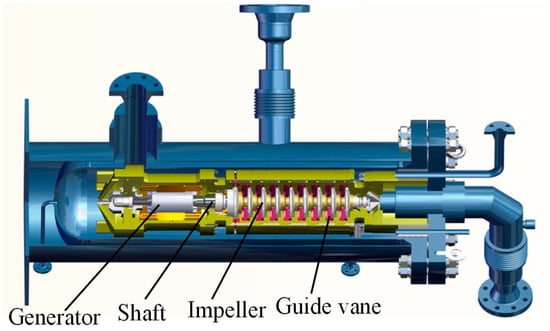
Figure 1.
Schematic of a liquefied natural gas (LNG) cryogenic expander.
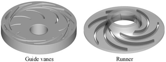
Figure 2.
Computations domain of an LNG cryogenic expander.

Table 1.
Parameters of the LNG cryogenic expander.
3. Numerical Method
3.1. Governing Equations
For cavitation flow, the homogeneous flow model is generally used. The homogeneous flow model defines the mixture of variables by averaging the parameters, and then the mixture conservation equation is used for the calculation. The governing equation is as follows:
The momentum equation is:
The energy equation is:
The fluid properties, , , , , are calculated from the local value of volume fractions of vapor and fluid phases:
where is the density, and are the velocity and temperature, respectively, which consist of the two phases. is the pressure and is the volume fraction. and are the dynamic viscosity and thermal conductivity of the homogeneous mixture, respectively. is the specific heat and L is the latent heat due to the phase change. Subscripts v and l refer to vapor and liquid, respectively. represents the mass transfer source term. and refer to the mass transfer rate source term due to evaporation and condensation, respectively. The vapor volume fraction is solved using the following transport equation:
Equations (1)–(8) are discretized by ANSYS-CFX software (SAS IP, Inc., Pittsburgh, PA, USA) to complete the simulation calculation of the expander.
3.2. Cavitation Model
The two-phase-flow mixture model and the Zwart–Gerber–Belamri mass transfer cavitation model [26] with a modified saturated pressure were executed after cavitation. The liquid–vapor evaporation and condensation rates for the present transport-based cavitation model are, respectively, shown as:
where and are the empirical coefficients of evaporation and condensation, respectively. In addition, is the nucleation site volume fraction and indicates the nucleation site radius. stands for the liquid vaporization pressure as a function of the temperature. According to the researches in the simulation of cryogenic cavitation [27,28,29], and have a significant impact on predictions of simulation, and the recommended values for those coefficients are , , and . The effects of turbulence on the cavitation are considered by correcting the saturation pressure as:
where is the local saturation pressure dominated by the temperature, is the turbulent pressure and is local turbulence energy.
A series of cryogenic liquid cavitation experiments conducted by Hord in the 1970s has become the experimental basis to verify the accuracy of the cavitation model. Because of the difficulty in performing the cryogenic cavitation experiment, Hord’ results are usually used to verify the accuracy of the simulation. In this part of the study, the 290 C experimental results are used as the verification target, the grid model is shown in Figure 3. The temperature and vapor volume fraction distribution of simulation results are shown in Figure 4. Figure 5 compares the pressure and temperature between the experiment and simulation, and the results are in good agreement with the experimental data. In this way, the accuracy of the cavitation model in calculating cryogenic cavitation is verified. Then, the cavitation model is used in the expander numerical simulation.
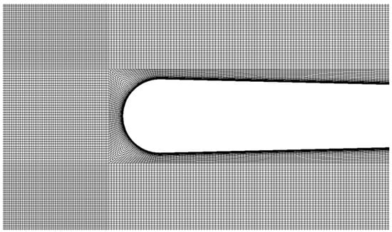
Figure 3.
Hydrofoil computational domain grid.
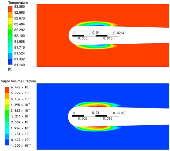
Figure 4.
The computed temperature and vapor volume fraction contours.
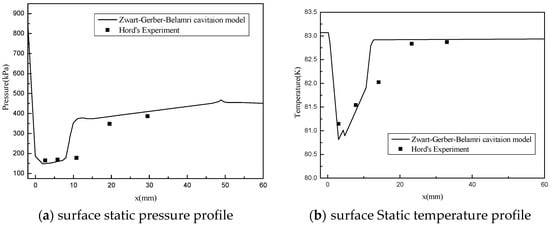
Figure 5.
Comparison of coefficients between the simulation and experiment.
3.3. Numerical Simulation
The whole calculation basin of the LNG cryogenic expander was meshed by the ANSYS ICEM software (SAS IP, Inc., Pittsburgh, PA, USA). The meshing is shown in Figure 6, and Figure 7 presents the grid independence. It is shown that the head changes a little when the total grid number is higher than 2.57 × 10⁶. The final calculation grid model is guide vane 1.37 × 10⁶, runner 1.20 × 10⁶, draft tube 0.50 × 10⁶.
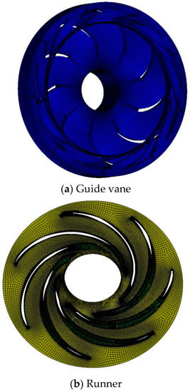
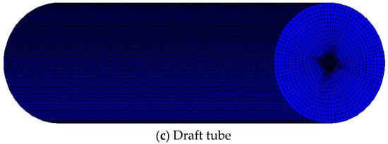
Figure 6.
Grid profile of the flow passage of the LNG cryogenic expander.
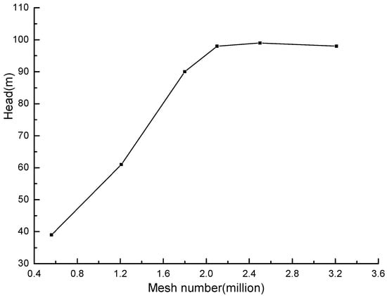
Figure 7.
The grid independence.
The commercial software ANSYS CFX was used to simulate the internal flow characteristics of the expander flow field. The turbulence model is selected as the SST k–ω model. The second-order upwind scheme was employed for the convective terms, and the central difference scheme was used for the diffusive terms in the governing equations in the numerical simulation. The frozen rotor model is used for the rotor–stator interfaces (guide vane–runner and runner–draft tube interfaces). The second wind scheme was used for the convective energy terms. The convergence criterion was set to . In this study, the velocity inlet and the pressure outlet conditions were set for the calculation. In addition, a smooth no-slip wall condition was imposed for the solid surfaces. In the cavitation simulation of liquid hydrogen, the thermodynamic properties of both liquid and vapor are updated from NIST database [30]. The head H and efficiency are defined in Equations (13) and (14), respectively
where Q is discharge, and is the angular velocity, which can be calculated using the rotational speed. The torque acting on the runner was calculated through ANSYS CFX simulation.
Because LNG is very dangerous, in our experiment, using liquid nitrogen as the medium, the flow rate of the expander is constant, and the expander performance under different operating conditions is obtained by changing the speed of the expander. The enclosed layout of the expander model test rig is presented in Figure 8. The density of the liquid nitrogen is 808 kg/m3 and the temperature is 77 K. The numerical simulation results of the LNG expander are compared with the experimental results in Figure 9. From the comparative analysis, we can see that in the range of working conditions, the numerical simulation results are in good agreement with the test results, the error between the simulation result and the test result at the design point is 1.5%, and the errors at low-speed and high-speed conditions are both less than 10%. Therefore, the numerical simulation results are reliable.
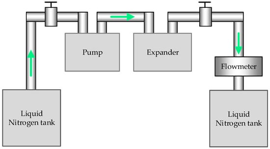
Figure 8.
Layout of the expander model test rig.
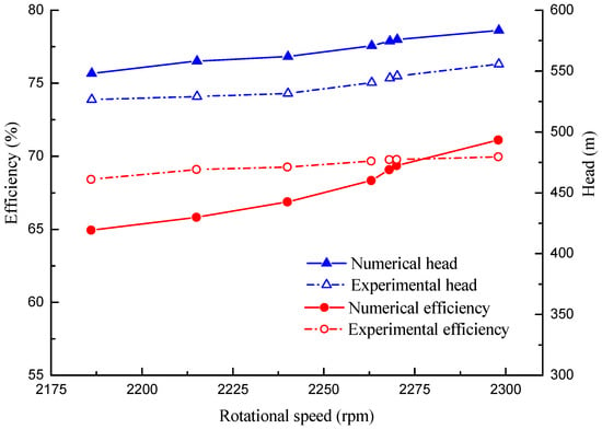
Figure 9.
Performance comparison between the numerical and experimental results.
4. Optimization Design System
4.1. Runner Design Method
The 3D design software TURBOdesign 5.2 (Advanced Design Technology, London, UK) [31,32] was used to describe the LNG cryogenic expander runner parametrically. For incompressible potential flow, the pressure distribution can be expressed as follows:
where is the pressure difference across the blade, is the relative meridional velocity on the blade surface, is swirl velocity and B is the number of blades, is also called the blade loading distribution.
When using TURBOdesign 5.2 to design runner blades, blade loadings were the most important parameters in determining the blade shape [31,32,33]. Blade loading distributions were given along the hub and shroud streamlines. The runner blade loadings of the hub and shroud were determined by using linear interpolation. The blade loading distribution is shown in Figure 10. Along each streamline, a three-segment distribution was adopted, including the loading at the leading edge of the runner blade DRVT, the linear slope SLOPE and connection point locations NC and ND. In the optimization process, extensive trial designs were made to check whether runners with reasonable shapes could be obtained. After these trial designs, three variables were fixed at , , and , where subscripts h and s refer to hub and shroud, respectively, and the variation ranges of the other runner blade variables were determined as shown in Table 2.
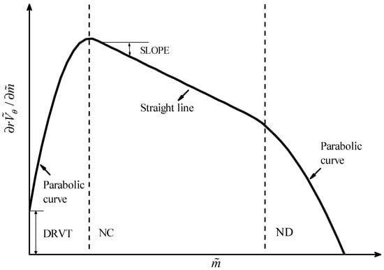
Figure 10.
Blade loading distributions.

Table 2.
Variation range of runner blade parameters.
4.2. Optimization Strategy
The response surface model (RSM) model is mainly used to construct the approximate relationship between optimization variables and optimization objectives to provide a basis for further optimization. The design of experiment (DOE) is an important mathematical method for systematically optimizing the sampling generation. In this study, the runner design parameters are taken as optimization variables, and the Latin hypercube test design method [34] is adopted to obtain different runner shapes in the space of the design parameters. The second-order response surface model is used to establish the approximate correspondence between independent variables and corresponding dependent variables, the expression is as follows:
where y is the optimization objective, n is the number of runner design parameters, and , are the runner parameters and constants, respectively.
The improved non-dominated sorting genetic algorithm (NSGA-II) was used to optimize the runner parameters in the design space. This algorithm uses a fast non-dominated sorting method to reduce the complexity of calculation, expands the optimization space by introducing elite strategy, ensures that the improved species will not be mistakenly abandoned in the process of evolution, and improves the optimization accuracy. The parameter settings for NSGA-II are shown in Table 3.

Table 3.
Parameter settings for NSGA-II.
For a description of the flow loss of the draft tube, the energy loss coefficient (ζ) and the average pressure recovery coefficient () in the draft tube are commonly used to characterize the flow in the draft tube, the expressions are as follows:
where are the inlet and outlet areas of the draft tube, respectively, and is total pressure, is static pressure, .
In Chen’s [35] multiobjects optimization strategy, the loss coefficient is chosen as an objective to optimize the structure of a Francis turbine draft tube. In the study by Galva’n [36], the loss coefficient of the draft tube is more sensitive to the pressure distribution of the draft tube inlet, which can better describe the velocity distribution of the draft tube inlet and the flow loss caused by the change of the draft tube inlet velocity. Therefore, the loss coefficient is chosen as one of the objective functions of multiobjective optimization. At the same time, to ensure the performance of the runner, the head of the single runner in the optimization process is also set as the objective function.
In the process of optimization, the single channel of the runner is used for the simulation calculation, the boundary conditions are set as shown in Figure 11, with liquefied nitrogen used in the experiment as the medium. Compared with the full-channel model, the grid of the single channel is greatly reduced, which can save calculation time.
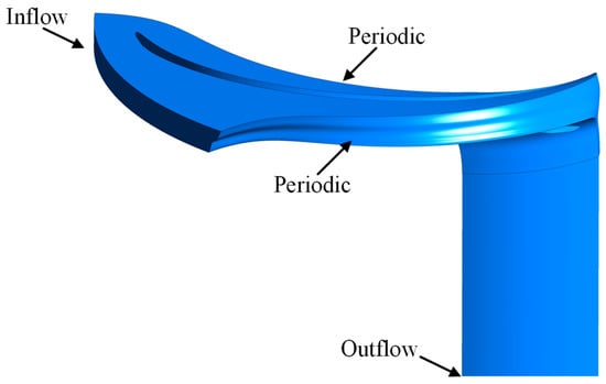
Figure 11.
Single-channel flow passage of runner.
The runner test model is obtained by changing the runner design parameters, and the head and energy loss coefficient in the draft tube under different runner design parameters are obtained by CFD numerical simulation. The explicit relationship between the runner design parameters and the objective function is obtained using the second-order RSM, and then the optimal solutions are obtained using the NSGA-II optimization method. According to the optimization results, the Pareto curve of the optimization target is obtained, and then the optimal design parameters of the runner are chosen. iSIGHT platform is used to complete the modeling of RSM and the subsequent optimization process.
5. Optimization Result
Figure 12 presents the black plots of the multiobjective optimization results, and the blue plots are the results on the Pareto front. Models A, B, and C (the red plots) were selected on the Pareto curve for further analysis. A comparison between the predicted values of the genetic algorithm and the numerical simulation results of CFD is shown in Table 4. There are some errors in the head and energy loss coefficients of the three models, but the results of different runners have the same trend, which verifies that the genetic algorithm can provide a reference for the design of runners.
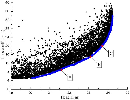
Figure 12.
Optimization results.

Table 4.
Comparison of the selected runners and the initial runner.
5.1. Effect of Blade Loading
Table 5 shows the runner blade loading of the optimized models chosen on the Pareto curve. As shown in Figure 13, the blade loading distributions, which show great similarity, are aft-loading and fore-loading on the hub and shroud for runners A, B, and C. Figure 14 shows the runners’ shapes.

Table 5.
Optimized parameters of the chosen models.
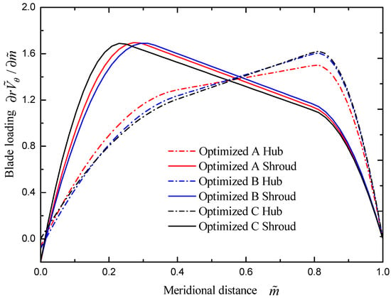
Figure 13.
Blade loading distributions of the optimized runners.
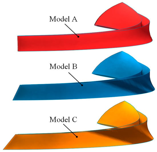
Figure 14.
Optimized Model A, B, and C blade shapes.
The pressure and gas volume fraction distribution in the draft tube of the three runner models and the original model are shown in Figure 15 and Figure 16. When the low-pressure area in the draft tube is large, the cavitation is serious, and the gas distribution area is large. Through the calculation of the numerical simulation results, when the cavitation is serious, the energy loss coefficient in the draft tube is larger, when the energy loss coefficient is small, the distribution of the low-pressure area in the draft tube is smaller, and the cavitation can be better suppressed. It is proven that the energy loss coefficient can reflect the severity of cavitation in the draft tube.
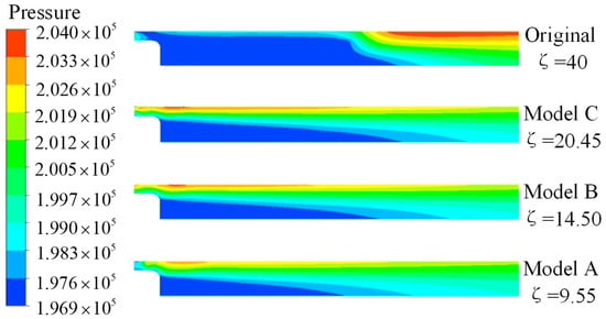
Figure 15.
Pressure distribution in the draft tube of the optimized and original runners.
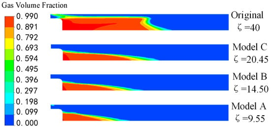
Figure 16.
Gas volume fraction distribution in the draft tube of the optimized and original runners.
According to the calculation results, the cavitation of the original model is the most serious, the energy loss coefficient of the draft tube is the largest, the inhibition effect of model A is the best, and the energy loss coefficient is the smallest.
According to the optimization results and CFD analysis, it can be found that runners with aft-loading and fore-loading on the hub and shroud have better performance considering the effects on the runner head and draft tube cavitation.
5.2. Effect of The Blade Lean
Based on the optimization results, more runners with the same blade loading distribution and different blade lean were designed to be investigated. Table 6 shows the blade loading distribution, with the blade lean ranging from −10° to 10°, as shown in Figure 17. Figure 18 shows the gas volume fraction in the draft tube, and the energy loss coefficients are also listed in Table 6.

Table 6.
Blade loading distribution of the designed models.
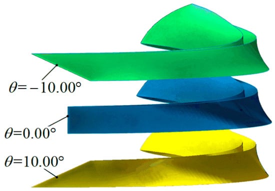
Figure 17.
Runners with different blade lean angles.
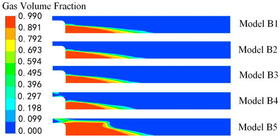
Figure 18.
Gas volume fraction distribution in the draft tube.
The results show that the runners with large positive or negative blade lean angles have large energy loss coefficients and the gas volume fraction distribution in the draft tube is worsening. When the blade lean angles are between 0° and 5°, the cavitation in the draft tube is improved, which can also be inferred from the optimization results on the Pareto curve. Therefore, large blade lean angles are not recommended to be used for the expander runner considering the cavitation in the draft tube.
6. Conclusions
A strategy for cavitation suppression in an LNG cryogenic expander draft tube by a multiobjective optimization method was employed in the present study. The process combines the runner design method, DOE, RSM, CFD analysis and genetic algorithm.
During the optimization, runners with different design parameters were obtained using the Latin hypercube test. The second-order RSM was used to describe the relationship between runner design parameters and objective functions, and then the final optimization models were obtained using the NSGA-II genetic algorithm.
The accuracy of the simulation of cryogenic liquid cavitation is verified by comparing with the experimental results of Hord, and the cavitation model is applied to the simulation of the cryogenic expander to obtain the cavitation flow in the draft tube.
The energy loss coefficient of the draft tube was used to evaluate the flow in the draft tube. Through the numerical simulation calculation, it was proven that the energy loss coefficient of the draft tube can be used to evaluate the cavitation severity of the draft tube. The more serious the cavitation is, the greater the energy loss coefficient is, as shown in Figure 16.
During the optimization process, the single runner head and the energy loss coefficient of the draft tube were taken as the optimization objectives. After optimization, the head is obviously increased, and the energy loss coefficient is reduced. The low-pressure area in the draft tube is obviously reduced and the cavitation is restrained to a certain extent. The runners on the Pareto curve have similar blade loadings. Considering the expander head and cavitation in the draft tube, it is recommended to design the expander runner with aft-loading and fore-loading on the hub and shroud.
The effects of blade lean angles for the cavitation in the draft tube were studied. It was found that large positive and negative angles are not recommended, and the runners with blade lean angles ranging from 0° to 5° have better performance for cavitation in the draft tube.
Author Contributions
Methodology, N.H. and B.Z.; Software, B.Z.; resources, Z.L.; writing—original draft preparation, N.H.; writing—review and editing, B.Z.; All authors have read and agreed to the published version of the manuscript.
Funding
This research was funded by National Natural Science Foundation of China (grant numbers: 51736008, 51679122); the National Key Research and Development Program of China (grant number: SQ2018YFB060154-02); the High Technology ship Research of Ministry of Industry and Information Technology of China (Grant No. [2014]503).
Conflicts of Interest
The authors declare no conflict of interest.
References
- Kimmel, H.E. Cryogenic LNG Expanders Reduce Natural Gas Liquefaction Costs; Natural Gas Logistics, Handling and Contracts: Bali, Indonesia, 2011; pp. 18–22. [Google Scholar]
- Chen, J.; Hua, Y.; Su, Q.; Wan, X.; Li, Z. Development and industrial tests of the first LNG hydraulic turbine system in China. J. Nat. Gas Ind. B 2016, 3, 283–290. [Google Scholar] [CrossRef]
- Song, P.; Sun, J.; Wang, K. Swirling and cavitating flow suppression in a cryogenic liquid turbine expander through geometric optimization. J. Power Energy 2015, 229, 628–646. [Google Scholar] [CrossRef]
- Hord, J. Cavitation in Liquid Cryogens II-Hydrofoils; National Aeronautics and Space Administration: Washington, DC, USA, 1973; CR-2156. [Google Scholar]
- Hord, J. Cavitation in Liquid Cryogens III-Ogives; National Aeronautics and Space Administration: Washington, DC, USA, 1973; CR-2242. [Google Scholar]
- Hsiao, C.T.; Ma, J.; Chahine, G.L. Multiscale tow-phase flow modeling of sheet and cloud cavitation. Int. J. Multiph. Flow 2017, 90, 102–117. [Google Scholar] [CrossRef]
- Du, T.Z.; Wang, Y.W.; Liao, L.J.; Huang, C.G. A numerical model for the evolution of internal structure of cavitation cloud. J. Phys. Fluids 2016, 28, 3–20. [Google Scholar] [CrossRef]
- Örley, F.; Trummler, T.; Hickel, S.; Mihatsch, M.S.; Schmidt, S.J.; Adams, N.A. Large-eddy simulation of cavitating nozzle flow and primary jet break-up. J. Phys. Fluids 2015, 27, 086101. [Google Scholar] [CrossRef]
- Kähler, G.; Bonelli, F.; Gonnella, G.; Lamura, A. Cavitation inception of a van der Waals fluid at a sack-wall obstacle. J. Phys. Fluids 2015, 27, 123307. [Google Scholar] [CrossRef]
- Utturkar, Y.; Wu, J.; Wang, G.; Shyy, W. Recent progress in modeling of cryogenic cavitation for liquid rocket propulsion. J. Prog. Aerosp. Sci. 2005, 41, 558–608. [Google Scholar] [CrossRef]
- Chen, T.R.; Huang, B.; Wang, G.Y. Numerical study of cavitating flows in a wide range of water temperatures with special emphasis on two typical cavitation dynamics. Int. J. Heat Mass Transr. 2016, 101, 886–900. [Google Scholar] [CrossRef]
- Chen, T.; Huang, B.; Wang, G.; Zhang, H.; Wang, Y. Numerical investigation of thermo-sensitive cavitating flows in a wide range of free-stream temperatures and velocities in fluoroketone. Int. J. Heat Mass Transf. 2017, 112, 125–136. [Google Scholar] [CrossRef]
- Chen, T.; Chen, H.; Liang, W.; Huang, B.; Xiang, L. Experimental investigation of liquid nitrogen cavitating flows in converging-diverging nozzle with special emphasis on thermal transition. Int. J. Heat Mass Transf. 2019, 132, 618–630. [Google Scholar] [CrossRef]
- Cao, X.L.; Zhang, X.B.; Qiu, L.M.; Gan, Z.H. Validation of full cavitation model in cryogenic fluids. J. Chin. Sci. Bull. 2009, 54, 1633–1640. [Google Scholar] [CrossRef]
- Huang, B.; Wu, Q.; Wang, G. Numerical investigation of cavitating flow in liquid hydrogen. Int. J. Hydrogen Energy 2014, 39, 1698–1709. [Google Scholar] [CrossRef]
- Fei, T.; Wen, L.J. Influence of thermodynamics effect on inducer rotating cavitation under low temperature condition. J. Rocket Propuls. 2013, 39, 29–34. [Google Scholar]
- Liu, Q.Z.; Su, W.T.; Li, X.B.; Zhang, Y.N. Dynamic characteristics of load rejection process in a reversible pump-turbine. J. Renew. Energy 2020, 146, 1922–1931. [Google Scholar] [CrossRef]
- Zhang, Y.; Liu, K.; Xian, H.; Du, X. A review of methods for vortex identification in hydroturbines. J. Renew. Sustain. Energy Rev. 2018, 81, 1269–1285. [Google Scholar] [CrossRef]
- Arispe, T.M.; De Oliveira, W.; Ramirez, R.G. Francis turbine draft tube parameterization and analysis of performance characteristics using CFD techniques. J. Renew. Energy 2018, 127, 114–124. [Google Scholar] [CrossRef]
- Yu, A.; Zou, Z.; Zhou, D.; Zheng, Y.; Luo, X. Investigation of the correlation mechanism between cavitation rope behavior and pressure fluctuations in a hydraulic turbine. J. Renew. Energy 2020, 147, 1199–1208. [Google Scholar] [CrossRef]
- Zhu, B.; Wang, X.; Tan, L.; Zhou, D.; Zhao, Y.; Cao, S. Optimization design of a reversible pump–turbine runner with high efficiency and stability. J. Renew. Energy 2015, 81, 366–376. [Google Scholar] [CrossRef]
- Chirkov, D.V.; Ankudinova, A.S.; Kryukov, A.E.; Cherny, S.G.; Skorospelov, V.A. Multi-objective shape optimization of a hydraulic turbine runner using efficiency, strength and weight criteria. J. Struct. Multidiscip. Optim. 2018, 58, 627–640. [Google Scholar] [CrossRef]
- Lu, Y.M.; Wang, X.F.; Wang, W.; Zhou, F.M. Application of the Modified Inverse Design Method in the Optimization of the Runner Blade of a Mixed-Flow Pump. Chin. J. Mech. Eng. 2018, 31, 105. [Google Scholar] [CrossRef]
- Liu, L.; Zhu, B.; Bai, L.; Liu, X.; Zhao, Y. Parametric Design of an Ultrahigh-Head Pump-Turbine Runner Based on Multiobjective Optimization. Energies 2017, 10, 1169. [Google Scholar] [CrossRef]
- Ma, Z.; Zhu, B.; Rao, C.; Shangguan, Y. Comprehensive Hydraulic Improvement and Parametric Analysis of a Francis Turbine Runner. Energies 2019, 12, 307. [Google Scholar] [CrossRef]
- Zwart, P.J.; Gerber, A.G.; Belamri, T. A two-phase flow model for predicting cavitation dynamics. In Proceedings of the Fifth International Conference on Multiphase Flow, Yokohama, Japan, 30 May–4 June 2004. [Google Scholar]
- Goel, T.; Thakur, S.; Haftka, R.T.; Shyy, W.; Zhao, J. Surrogate model-based strategy for cryogenic cavitation model validation and sensitivity evaluation. Int. J. Numer. Methods Eng. 2008, 58, 969–1007. [Google Scholar] [CrossRef]
- Senocak, I.; Shyy, W. Interfacial dynamics-based modeling of turbulent cavitating flows Part-1: Model development and steady-state computations. Int. J. Numer. Methods Fluids 2004, 44, 975–995. [Google Scholar] [CrossRef]
- Sun, T.Z.; Ma, X.F.; Wei, Y.J.; Wang, C. Computational modeling of cavitating flows in liquid nitrogen by an extended transport-based cavitation model. Sci. China Technol. Sci. 2016, 59, 337–346. [Google Scholar] [CrossRef]
- Lemmon, E.W.; McLinden, M.O.; Huber, M.L. Reference Fluid Thermodynamic and Transport Properties, Standard Database 23 version 7.0; NIST: Gaithersburg, MD, USA, 2002. [Google Scholar]
- Zangeneh, M. A compressible three-dimensional design method for radial and mixed flow turbomachinery blades. Int. J. Numer. Methods Fluids 1991, 13, 599–624. [Google Scholar] [CrossRef]
- Zangeneh, M.; Goto, A.; Harada, H. On the design criteria for suppression of secondary flows in centrifugal and mixed flow impellers. J. Turbomach. 1998, 120, 723–735. [Google Scholar] [CrossRef]
- Bonaiuti, D.; Zangeneh, M. On the coupling of inverse design and optimization techniques for the multiobjective, multipoint design of turbomachinery blades. J. Turbomach. 2009, 131, 21014–21029. [Google Scholar] [CrossRef]
- Myers, R.H.; Montgomery, D.C.; Anderson-Cook, C.M. Response Surface Methodology: Process and Product Optimization Using Designed Experiments; John Wiley & Sons: Hoboken, NJ, USA, 2009. [Google Scholar]
- Chen, Z.; Baek, S.H.; Cho, H.; Choi, Y.D. Optimal design of J-groove shape on the suppression of unsteady flow in the Francis turbine draft tube. J. Mech. Sci. Technol. 2019, 33, 2211–2218. [Google Scholar] [CrossRef]
- Galván, S.; Rubio, C.; Pacheco, J.; Mendoza, C.; Toledo, M. Optimization methodology assessment for the inlet velocity profile of a hydraulic turbine draft tube: Part I—Computer optimization techniques. J. Global Optim. 2013, 55, 53–72. [Google Scholar] [CrossRef]
© 2020 by the authors. Licensee MDPI, Basel, Switzerland. This article is an open access article distributed under the terms and conditions of the Creative Commons Attribution (CC BY) license (http://creativecommons.org/licenses/by/4.0/).