Article

Thermally Optimum Spacing between Inner Plates in Natural Convection Flows in Cavities by Numerical Investigation

Department of Thermal and Fluids Engineering, Technical University of Cartagena, Doctor Fleming s/n, 30202 Cartagena, Spain
Processes 2020, 8(5), 554; https://doi.org/10.3390/pr8050554
Submission received: 8 April 2020 / Revised: 27 April 2020 / Accepted: 3 May 2020 / Published: 9 May 2020
(This article belongs to the Special Issue Advancement in Computational Fluid Mechanics and Optimization Methods)

Abstract

:
Buoyancy-driven airflow that included two isothermal inner plates established in a vented cavity is investigated numerically. The thermally optimum wall-to-wall spacing of the immersed channel, as well as its dependence with respect to the relevant governing parameters, are determined. Results are presented as a function of the aspect ratio b/H for a wide range of Rayleigh numbers RaH. A logarithmic correlation for the optimum (b/H)opt as a function of RaH is presented. In addition, since the outlined configuration might be subject to intense heating conditions, the influence of considering variable thermophysical properties is also included in the analysis. In fact, an appreciable influence of the variation of properties on (b/H)opt is also detected for a representative value of RaH = 109. Obtained results can be directly applied to the optimization of electronic equipment cooling, or even to thermal passive devices in buildings.

1. Introduction

From the pioneering experimental study of Elenbaas [1], configurations formed by vertical heated plates with fluid flows induced by buoyancy effects have been the topic of several studies (Incropera and De Witt [2], Bejan [3]). The natural convection is a mode of heat transfer that presents undoubted advantages, under given circumstances. The vertical channel configuration with isothermal heating (Figure 1a) can be regarded as the most typical analyzed configuration. A relevant review of benchmark solutions for natural convection flows in vertical channels was presented recently by Desrayaud et al. [4].
The 
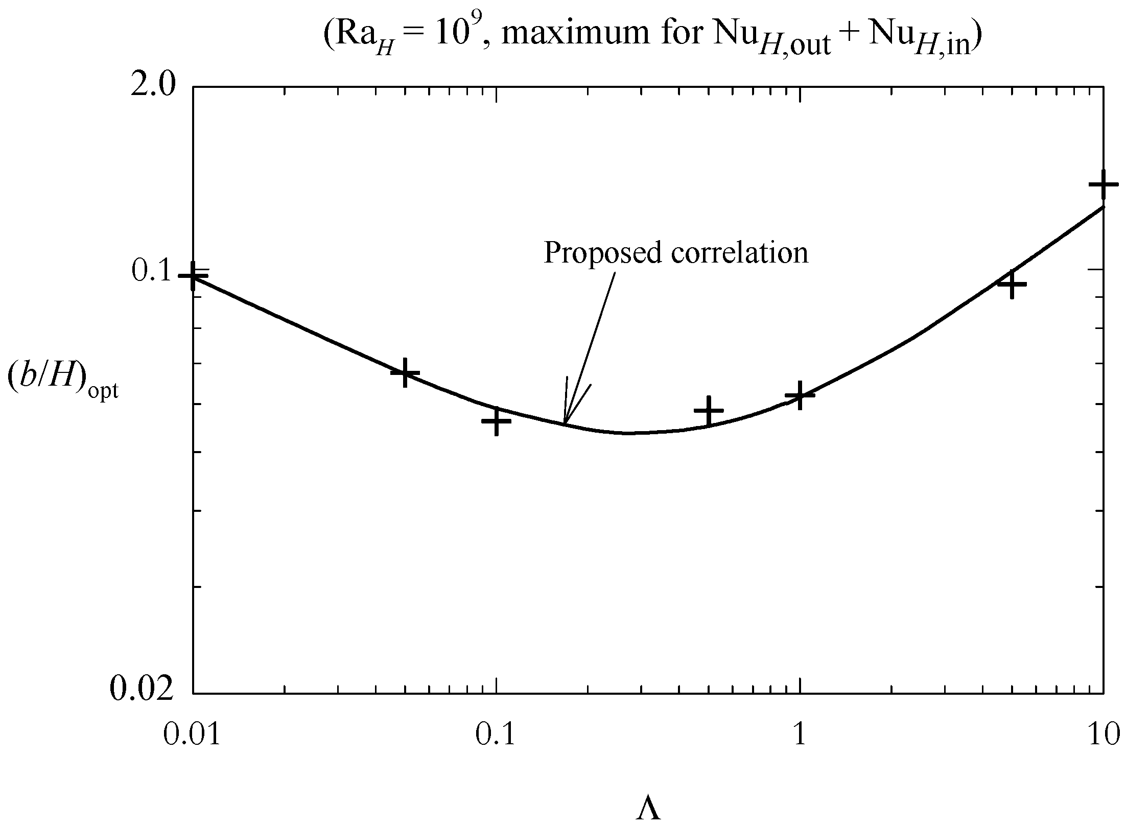
optimization problem for the described issue is represented by the electronic equipment cooling. In this case, one of the most important objectives consists of dissipating the heat generated in the devices to avoid overheating. The determination of the thermally optimum spacing bopt (between the plates or walls forming the vertical channel) that maximizes the heat transfer rate per unit area can achieve the thermal optimization of the system. The first criterion for obtaining bopt was reported by Bodoia and Osterle [5]. Analytically, a given 
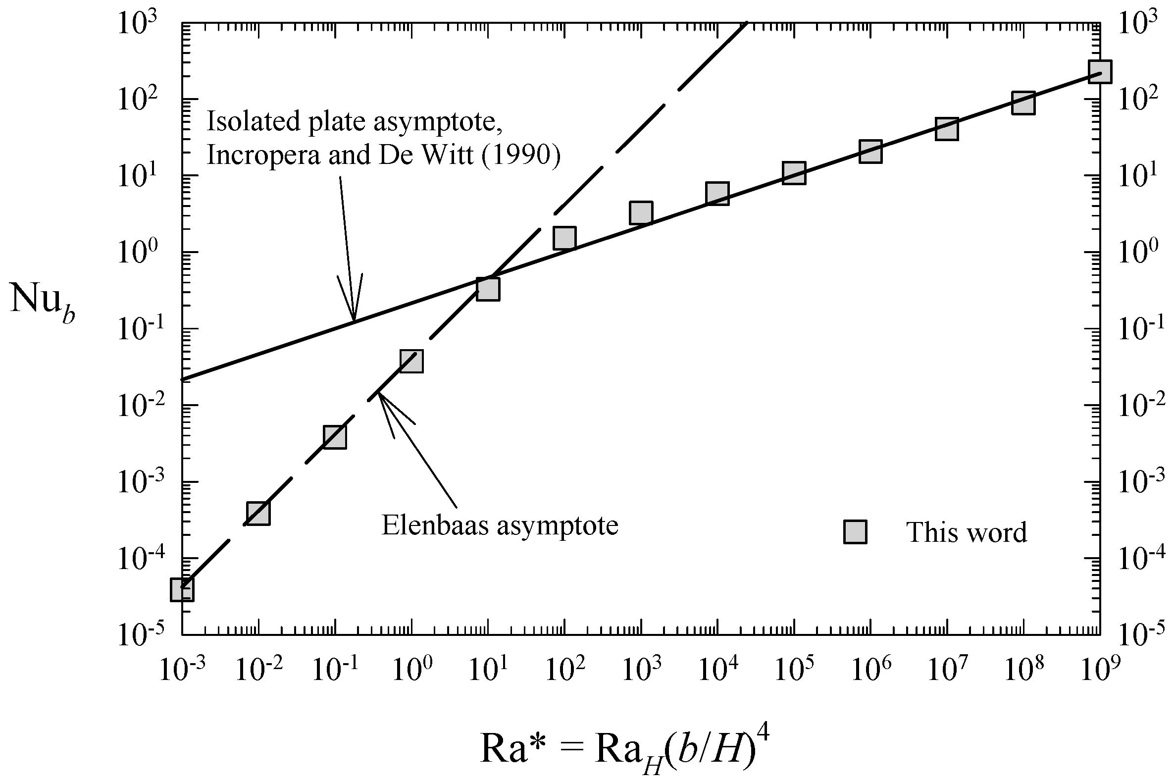
optimization function can be obtained from the appropriate correlations for calculating the heat transfer rate. Bar-Cohen and Rohsenow [6] and Zamora and Hernández [7] employed different correlations for the average Nusselt number for achieving this aim, with laminar flow assumption. The optimum was reached for a modified Rayleigh number Ra* (based on the inter-plate spacing) placed near the crossing point between the fully-developed and the boundary layer asymptotes; in this manner, its value depends on the fitting constants used in the average Nusselt number correlations. In reality, the idea of considering an isothermal vertical channel as a configuration for obtaining the optimal spacing between plates makes physical sense if this geometry is regarded as a representative sample of the channels formed with equally-spaced isothermal plates located into an available horizontal gap L. When the number of plates increases, the total area for heat transmission increases, but in turn the temperature gradient at the walls decreases, as well as the average heat transfer coefficient. Since the described effects become the opposite when the number of plates decreases, then a thermally optimum wall-to-wall spacing can be encountered. Note that if the theoretical bopt is bopt < L, a sole channel must be formed. The global heat transfer could not be maximum in this case, but anyhow its value will be higher than that reached generating more than one channel in the available space.
In some cases (in passive ventilation systems, for instance), the dynamic optimization is clearly interesting. Here, obtaining the maximum induced mass-flow rate can be the main objective for ventilation purposes (Zamora and Kaiser [8], Zavala-Guillén et al. [9]). Previously, the authors carried out calculations for obtaining both thermal and dynamic optimization in geometries concerned to thermal passive systems of buildings (see Zamora and Kaiser [8]).
Other aspects of the problem can be treated; for instance, finned surfaces in natural convection provide relevant improvements in the thermal performance. Therefore, the distribution of heat sources can be analyzed for achieving the optimal arrangement (da Silva et al. [10], Zhang and Liu [11]).
More realistic configurations should be regarded for obtaining practical results. As expected, several works dealing with the geometric optimization of cavity configurations for obtaining the maximum heat transfer by buoyancy effects can be found in the literature (Aounallah et al. [12], for cavities with curved walls; Biserni et al. [13], for H-shaped cavities; Lorenzini et al. [14], for T-shaped cavities; Lorenzini and Rocha [15], for cavities with T-Y shape, among others). A feasible analysis procedure consists of using both the scale analysis method and the intersection of the asymptotes obtained for different regimes of the flow (da Silva and Gosselin [16], for instance). This way is similar to that followed by Bar-Cohen and Rohsenow [6] and Zamora and Hernández [7]. Another method is based on the Constructal Law of Bejan (Bejan [17], Bejan and Lorente [18]). These authors pointed out that, essentially, the constructal theory consists of global objectives and global constraints, whereas the geometry of the flow is unknown, i.e., the geometry is not previously assumed, but it is deduced. Alternative configurations and shapes are considered in the literature (da Silva and Gosselin [16], among others). Two configurations for the buoyancy-induced airflows in vertical channels have been studied in a previous work (Zamora [19]); one a smooth, curved channel, and the other a channel with several sharp changes of direction. For any given circumstances, the performance of the alternative outlined configurations can be considered better than that corresponding to a straight channel. This is a representative case, in which the geometries are mainly defined, and generalized enough correlations for the Nusselt number are not available; therefore, massive computational data (or experimental, if applicable) should be analyzed in order to find possible optimal situations.
For simulating the buoyancy effects, the well-known Boussinesq approach assumes constant properties of fluid, except for density variations exclusively due to temperature variations in the vertical component of the momentum equation. When the influence of variation of the air thermophysical properties is taken into account, a contrasted result found in the literature is that heat transfer coefficients and the induced mass-flow rate are considerably lower than those obtained under non-Boussinesq conditions. This particular effect can be attributed to the increase of the air viscosity (viscous drag) and the decrease of the air density, which produces an additional thermally-induced pressure drop (thermal drag), as the temperature difference increases (Zhong et al. [20], Guo and Wu [21]). In other words, both the viscous drag and the thermal drag increase faster than the buoyancy force when the temperature increases. The flow patterns could be affected strongly by the fluid variable properties for intense heating conditions; in this way, it can be expected that the thermally optimum inter-plate spacing (if it exists) is also affected by the described phenomenon.
In present work, a realistic situation that consists of considering a limited space, i.e., a vented cavity, into which a vertical channel is placed, is outlined (see Figure 1b). The spacing between the plates forming the channel can vary, but the dimensions of the cavity remain constant. The physically periodic conditions of the array of plates described above disappear, and thus the geometrical surroundings of the isothermal channel have a relevant influence on the behavior of the convective airflow. In this case, the area dedicated to convective heat transfer does not vary, but in turn, the thickness of the thermal boundary layers adjacent to heated walls varies strongly when the inter-plate spacing b changes. Therefore, a thermally optimum wall-to-wall spacing could exist; its determination constitutes the aim motivation of this work, as well as the simulation of the evolution of air properties. The adopted approach is numerical; results are presented as a function of the inter-plate spacing for a wide range of Rayleigh numbers. In view of the fact that the main applications of the outlined configuration might be subject to intense heating conditions, the influence of considering variable thermophysical properties of air is also included in the study. It is foreseeable that some effects could be explained by the flow configuration changes when the relevant parameters vary.

2. Materials and Methods

Figure 1 shows the configurations outlined in this paper. The first one is a typical vertical channel (Figure 1a); the height is H (y-direction) and the spacing between walls is b (x-direction); the relationship b/H is commonly named the aspect ratio. Figure 1b shows the configuration proposed for the numerical simulations; the dimensions of the cavity are HT in y-direction and L in x-direction, whereas the vents have a width equal to bV; a standard vertical channel (b × H) is placed centrally into the cavity; the thickness of the plates is considered negligible. A square cavity, L/HT = 1, is considered; the ratio between channel and cavity heights is H/HT = 1/2, and the width of vents is given by bV/HT = 0.075. The flow enters mainly through the lower vents and goes out mainly through the upper one.
The plates of the channel are considered isothermal at Tw, whereas the reference (ambient) conditions for air are given by p = 105 N/m2 and T = 293 K. In this manner, the relevant parameters to be considered are based on the height of plates H and on the characteristic temperature difference ΔT = TwT. Hence, the Rayleigh number is defined as RaH = GrH Pr, being GrH the Grashof number based on H, GrH = (TwT) H3/ν2, with g the gravity acceleration, β = 1/T (perfect gas assumption), ν the kinematic viscosity of the fluid, and Pr the Prandtl number of the fluid (Pr = 0.7 in this work). The range of the Rayleigh number considered is 103–1011 with turbulent simulation, which includes the whole range of typical performance conditions.
The average Nusselt number at heated, isothermal walls is calculated as follows
NuH = −H [(∂T/∂x)w/(TwT)] dy.
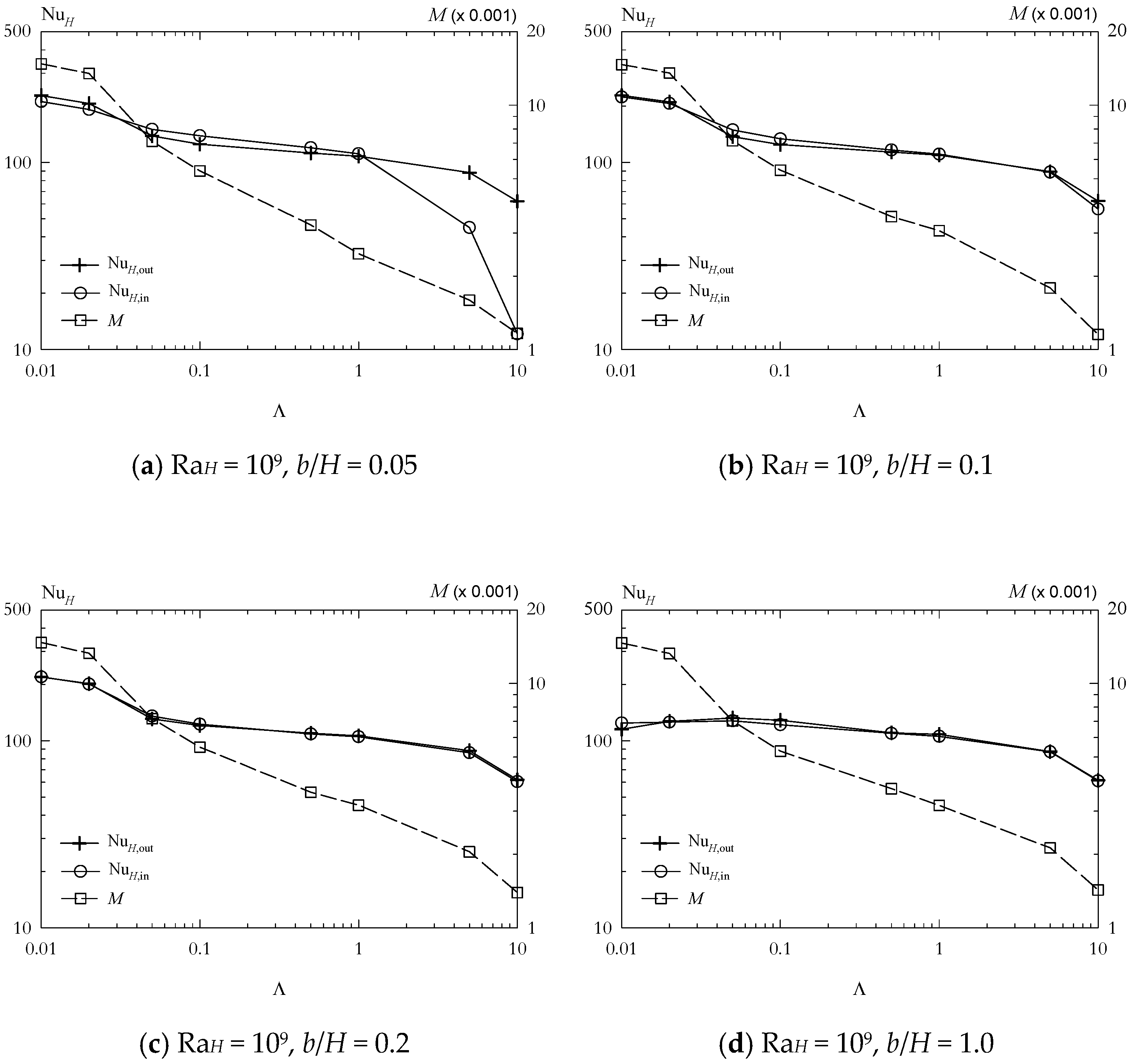
The Nusselt number calculated at the plate side facing the surrounding cavity wall is denoted with subscript out, and that calculated at the side facing the other plate is denoted with in.
The buoyancy-induced incoming (or outgoing) dimensionless mass-flow rate M is
M = m/ρν,
m being the two-dimensional mass-flow rate.
Lastly, for evaluating the fluid variable properties effects, the heating parameter can be defined as follows
Λ = (Tw − T)/T.
For low enough values of Λ, the influence of variable properties is negligible, and therefore the Boussinesq approach can be employed. In this work, this limit is achieved for the lowest value considered of the heating parameter, Λ = 0.01. For analyzing the variable properties effects, the range of values of Λ considered for numerical simulations is 0.01–10, which includes the whole range of typical situations.
Regarding the mathematical approach, the two-dimensional form of the elliptic time-averaged Navier–Stokes equations (continuity, momentum, and energy) for the turbulent airflow (see Zamora and Kaiser [8] for more details), are solved numerically by using the general-purpose Phoenics code (Phoenics Encyclopaedia [22]), which is based on a finite-volume procedure. The driving (buoyancy) force is calculated directly from density variations (instead of from temperature variations such as is advocated by the Boussinesq approach), and it is implemented in the vertical component of the momentum equation. The selected turbulence model for solving the closure problem is the version of the two-transport equations kω model proposed by Wilcox [23], which includes a low-Reynolds extension for near-wall turbulence. If the mesh includes some nodes into the boundary layer, the entire laminar–transitional–turbulent behavior can be appropriately simulated. The obtained results have been compared with those computed through the SST kω turbulence model, but they are not presented because of differences tend to be negligible provided that the grid was refined enough, mainly near the walls. Now then, the necessary computations times are, in general, higher with the SST kω model.
Regarding the boundary conditions, the plates of the channel are considered with a uniform hot temperature T = Tw, whereas a cold temperature T = T is imposed on the fluid outside the cavity. The walls forming the cavity are treated as adiabatic. The non-slip condition for velocity and turbulent kinetic energy is imposed at all the walls. At the inlet sections (lower vents), the mass-flow rate is assumed to be dependent of the square root of the difference between the ambient pressure p and the pressure p computed at each inlet cell (this can be regarded as a result of the Bernoulli equation application at the surroundings of the cavity), whereas the temperature is fixed at T. At the outlet sections (upper vents), the pressure is fixed at p, and the streamwise variations of velocity components, temperature, and turbulent variables are neglected.
From the experimental data available in the literature (Çengel and Cimbala [24], for instance), own correlations are developed for expressing the evolution of the thermophysical properties of air as a function of temperature. Thermal conductivity, specific heat at constant pressure and kinematic viscosity are increasing with absolute temperature T,
κ(T) = 5.061 × 10⁻³ + 7.387 × 10⁻⁵ T − 1.215 × 10⁻⁸ T2,
cp(T) = 923.2 + 2.619 × 10⁻¹ T − 4.872 × 10⁻⁵ T2,
ν(T) = −1.448 × 10⁻⁵ + 8.653 × 10⁻⁸ T + 4.802 × 10⁻¹¹ T2,
valid for 273–2273 K, with determination coefficients R2 equal to 0.9937, 0.9993, and 0.9990, respectively. In addition, the perfect gas assumption ρ = p/RT, being R the air constant, equal to 287 J/kg.K indicates that since variations of pressure are low, the density of air is mainly decreasing with T. These correlations are implemented into the Phoenics code for simulating the thermophysical air behavior.
Regarding the numerical details, the time-dependent procedure is employed for obtaining the numerical results; a fully-implicit scheme for the time discretization is used. A scale analysis in the y-momentum equation gives a typical vertical velocity in the order V ≈ [T)H]1/2 for natural convection flows, by equating convective and buoyancy terms, v(∂v/∂y) ≈ T). The characteristic time can be estimated as t0H/V. For obtaining the appropriate accuracy, the employed values of time step Δt are into the range 0.01–0.25. A number of 40 iterations allows us to achieve spatial convergence in each time step. Finally, most of the computations lead to obtaining essentially steady-state solutions.
The equations are discretized by a staggered-grid scheme. Structured, cartesian meshes are employed (120 × 120 cells in most cases), with different power-law distributions to produce fine meshing near the walls, as aforementioned. A typical grid is shown in Figure 1c. The accuracy of the numerical results is tested by a grid dependence study; both the dimensionless sub-layer scaled distance y+ and the total number of cells are taken into account for analyzing the influence of meshing on the results (see Zamora and Kaiser [8]). Parameter y+ is revealed as the most influential so that for low enough values of y+, the obtained results are affected mainly by the given value of y+. Therefore, the results presented are computed using grids with y+ low enough (mainly in the range 0.1–0.5), achieving in this way the grid independence.
The numerical results are obtained through a second-order “muscl” (non-linear) differencing scheme (Phoenics Encyclopaedia [22], Van Leer [25]) for the convective terms of the momentum, energy, and turbulence transport equations. Focusing on numerical convergence, the relative change of any dependent variable in each iteration is less than 10−5. The relative residuals for mass, momentum, energy, and turbulent variables for the full flow field are less than 10−4.

3. Results and Discussion

Both the mathematical and the numerical modeling of the concerned matter have been tested and validated in several above works by comparing the obtained results with experimental and numerical data taken from the literature for different morphologies. Readers can find more detailed information in Zamora and Kaiser [8] and Zamora [19], for instance. Illustratively, a basic comparison with benchmark, asymptotical solutions is presented in Figure 2.

3.1. Evolution of Relevant Parameters vs. Rayleigh Number

From now on, attention is posed in the vented cavity configuration given by Figure 1b. As a first step, a very low value of the heating parameter Λ = 0.01 is considered for avoiding the effects of the variable thermophysical properties of air. Given the considered morphology, now it can be expected that solution depends on the Rayleigh number RaH and on the geometrical aspect ratio of channel b/H, provided that dimensions and shape of cavity remain constant, as well as the Prandtl number Pr. Consequently, it seems appropriate to base the Rayleigh number on H, and thus computations are carried out for RaH = 103–1011, varying the aspect ratio b/H from 0.01 to 1.5. Heat transfer coefficients are evaluated through the average Nusselt number, also based on H, which is calculated at the outer (NuH,out) and at the inner (NuH,in) faces of one of the plates forming the channel, as above explained. Note that the global heat dissipation of the system concerns the sum (NuH,out + NuH,in), which can be named as the global Nusselt number.
The evolution of NuH,out, NuH,in, (NuH,out + NuH,in), and M as a function of RaH is presented in Figure 3, for different values of b/H (0.05, 0.1, 0.2, and 1.0). The evolutions are clearly logarithmic, but relevant differences exist between trends of NuH,out and NuH,in for low enough values of RaH; it can be seen that these differences tend to decrease as b/H increases (trends becomes very similar for high enough values of b/H, as Figure 3d shows, for b/H = 1.0). However, the trend of non-dimensional mass-flow rate M seems to be invariable versus b/H. This can be explained by the fact that the induced buoyancy force is roughly the same for each value of Rayleigh number, irrespective of the distance between plates, although differences in the thickness of the thermal boundary layers adjacent to heated walls can produce relevant discrepancies between the Nusselt numbers calculated at both sides of plates.
Both the mass-flow rate and the global Nusselt number can be correlated well through power-law functions. Taking a representative value of aspect ratio b/H = 0.2 (Figure 3c), the following equations summarizes well the obtained results
M = 0.321 (RaH)0.519, RaH = 103–1011,
with an average deviation equal to 2.9%, peak error 4.5% and R2 = 0.9999, and
(NuH,out + NuH,in) = 0.0905 (RaH)0.485, RaH = 103–105,
(NuH,out + NuH,in) = 0.708 (RaH)0.304, RaH = 105–108,
(NuH,out + NuH,in) = 0.174 (RaH)0.380, RaH = 108–1011,
with an average deviation equal to 2%, peak error of 4.4%, and R2 = 0.9998. Note that for the global Nusselt number, three different trends are mandatorily distinguished.

3.2. Thermally Optimum Inter-Plate Spacing

Now focusing on the possibility of finding maximum heat transfer conditions when plate-to-plate spacing varies, systematic results are obtained for the wide range of Rayleigh number considered, and b/H from 0.01 to 1.5, as above explained. Results obtained for selected values of RaH are graphically presented in Figure 4. For a given value of the RaH, when b/H is very low, then NuH,in ⇒ 0 (at the end, the two plates are joined and would form a sole plate), but NuH,out reaches its maximum value, due that the plate is far enough from the cavity wall, and its thermal behavior is similar to that corresponding to an isolated plate. As b/H increases, heat transmission between the inner side of plates and the fluid increases, whereas the available space comprised between the surrounding (adiabatic) wall of the cavity and the outer side of plates decreases, thus entailing a decrease in the Nusselt number. These two opposite effects can justify the existence of an optimal value of aspect ratio, (b/H)opt. For the full understanding of these effects, the structure of the fluid motion should be taken into account; the buoyant plume generated by the heated channel is divided into two symmetrical parts under given circumstances, and they mainly escape through the upper vents. However, in some cases, recirculation zones appear and tend to modify the expected flow pattern.
For a given value of b/H, when the value of RaH is very low, the conduction effects produced meant that the cavity core was quite hot, and the heat dissipation was low; that is to say, the thickness of the thermal boundary layer adjacent to heated walls is considerably high. This trend changes as RaH increases, and then the behavior of the computed Nusselt numbers also change. For low enough values of RaH, NuH,out is always decreasing with b/H, whereas in turn, NuH,in is increasing; this trend changes for the case RaH = 106, from which the evolution of both Nusselt numbers as a function of aspect ratio tends to be almost coincident. For RaH > 107, the NuH,in curve exhibits a not too pronounced maximum (Figure 4c), but this maximum is more pronounced as RaH increases. Note that for some intermediate values of RaH, an unexpected detachment of curves corresponding to NuH,out and NuH,in for high enough values of b/H is detected. This can be related to a certain asymmetric flow pattern that is encountered under given circumstances.
Now, let us to focus the attention on the global Nusselt number (NuH,out + NuH,in). In this case, a relevant maximum value is encountered for all the investigated values of RaH (Figure 4). Appropriately extrapolating the maximum values of the spline curves depicted in each case, the maximum heat transfer is found at b/H = 0.962 for RaH = 103, at b/H = 0.415 for RaH = 104, at b/H = 0.248 for RaH = 105, and so on. The trend of the optimal aspect ratio (b/H)opt decreases as RaH increases. This fact can be explained by the progressive narrowing of the thermal boundary layer when the Rayleigh number increases, for a given value of b/H. This finding is similar to that exposed in Zamora and Kaiser [8], for Trombe wall shaped channels (thermal passive device). In addition, note that the higher value of RaH, the higher the intensity (or relevance) of the maximum. Although the maximum is slightly pronounced for low values of RaH, for the highest value of RaH = 1011, the (maximum) global Nusselt number obtained for (b/H)opt = 0.0680 is in the order of 2.5 times the value computed for the highest value of b/H.
In Figure 5, the obtained values of (b/H)opt are shown as a function of Rayleigh number RaH. Note that the trend is clearly logarithmic and that two different decreasing trends can be discerned. The slope is lower when the conduction effects are no longer important. The following blended-type equation is appropriate for correlating the numerical results
(b/H)opt = {[12.0 (RaH)−0.365]n + [0.495 (RaH)−0.0782]n}1/n,
with n = 3.20. The average deviation is equal to 2.4%, and the peak error is 4.5%.
Regarding the mass-flow rate, it is evident in Figure 4 that the behavior of M is mainly monotonous, and no significant optimal points can be deduced. Although it seems that the maximum values of M are reached for b/H ≈ 0.35 for high enough values of RaH, this cannot be considered as too relevant, given the scarce differences between the obtained values.

3.3. Influence of the Variable Thermophysical Properties

The analysis of the influence of variable thermophysical properties, which can be relevant for more intense heating conditions than that above considered (Λ = 0.01), is conducted for a representative value of Rayleigh number RaH = 109.
Firstly, the advised decreasing of the computed relevant parameters when heating parameter Λ increases is investigated. Figure 6 shows the obtained results for aspect ratios b/H = 0.05, 0.1, 0.2 and 1, with Λ varying from 0.01 to 10. The expected decrease in NuH at heated walls and in M is confirmed in this figure; the increasing of both the thermal drag and the viscous drag becomes higher than that corresponding to buoyancy force for high enough values of Λ, producing in this manner sizeable decays in the trends of relevant properties. Evolutions of M and NuH are different. In the case of M, the decay is essentially the same irrespective of the value of b/H, which confirms the behavior explained above. Note that the decreasing ratio is in the order of 2.5 between results obtained for Λ = 0.01 and Λ = 0.1, whereas it is in the order of 10 for Λ varying from 0.01 to 10. Regarding the Nusselt numbers, it can be observed that in general, the decay of results is lower; in addition, the behavior of NuH,out and NuH,in tends to be essentially the same as b/H increases, following the trend exposed above. Representative ratios can be given for illustrating this fact; for b/H = 0.1, maximum decay in both NuH,out and NuH,in are in the order of 4 (with Λ from 0.01 to 10), but for b/H = 1, the maximum decay falls to 2 (also from Λ = 0.01 to 10), approximately.
Secondly, the evolution of the thermally optimum plate-to-plate spacing for high values of Λ is investigated. Results obtained for Nusselt numbers and M, with RaH = 109, and values of Λ = 0.01, 0.1, 0.5, 1, 5, and 10, as a function of b/H, is shown in Figure 7. By analyzing the succession of Figure 7a–f, a relevant finding is that the evolution of heat transfer coefficients tends to be more homogeneous as Λ increases. This fact could be explained by the progressive thickening of the thermal boundary layers adjacent to walls when Λ increases, as well as by the consequent heating of the core regions of the cavity. Although optimal points are also detected for the global Nusselt number (NuH,out + NuH,in), the relevance of the maximum tends to decrease as Λ increases, in accordance with the above explanation. From appropriate interpolation of the obtained curves, the corresponding values of (b/H)opt are included in Figure 7.
Trends of results obtained for (b/H)opt as a function of Λ is also logarithmic, as can be observed in Figure 8; a relevant finding is that a minimum is detected roughly for Λ = 0.2. The following equation summarizes acceptably well the trend of results,
(b/H)opt = 0.0655 + 0.0152 ln Λ + 0.00485 ln2 Λ,
with an average deviation of 3.6%, peak error equal to 8.1%, and R2 = 0.9880. Although results are not presented, it is checked that trends can vary for other values of RaH, and therefore the explained behavior should not be extrapolated to values of RaH different to the considered 109, because of the variability of flow regimes that can be characterized throughout the whole range of values studied.

4. Discussion of Flow Patterns

Flow patterns are shown in Figure 9, Figure 10 and Figure 11. Figure 9 illustrates the thermal flow patterns that are found for two different Rayleigh numbers and two different aspect ratios. Here, it can be considered that results are obtained as the Boussinesq approach proposes since that Λ = 0.01, and therefore the air properties are considered almost constant. Note that for low enough values of RaH, the temperature field tends to be more homogeneous throughout the cavity than for higher values. The buoyant plumes generated at the upper part of heated plates are clearly more recognizable when b/H is low enough, and for b/H high enough, plumes are rapidly routed towards the upper exit vents. Characteristic values of dimensionless temperature difference θ = (TT)/(TwT) are depicted in this figure.
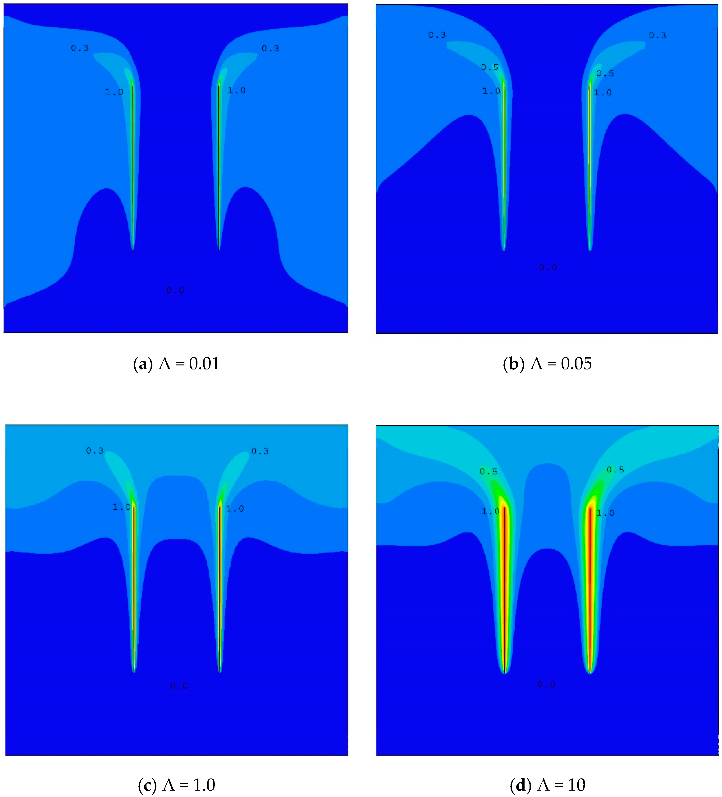
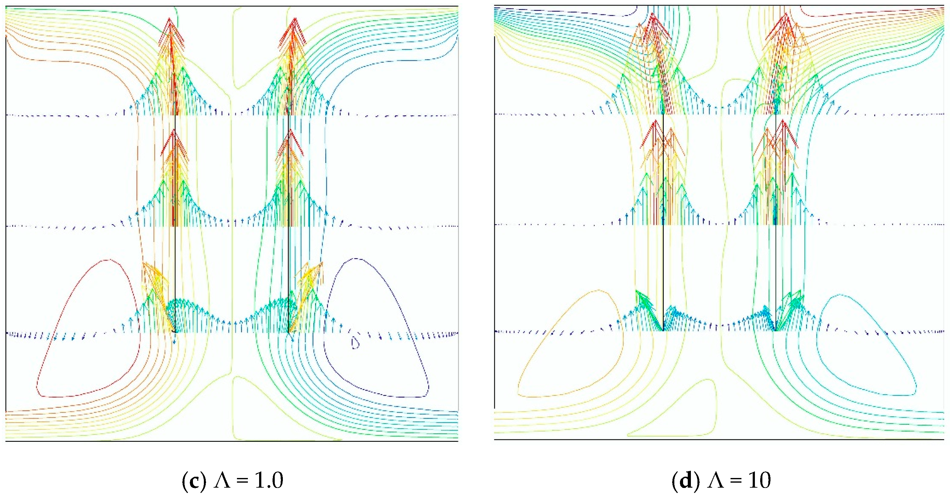
The effects of variable thermophysical properties are graphically depicted in Figure 10 and Figure 11. The first shows the filled contours of temperature, and the second, streamlines and selected velocity profiles, for a characteristic value of Rayleigh number RaH =109, aspect ratio b/H = 0.5, and different values of heating parameter Λ. In Figure 10, it is evident the progressive thickening of the thermal boundary layers adjacent to heated walls as Λ increases. The isotherms tend to occupy a larger portion of the cavity for higher values of Λ, and the Nusselt numbers at walls tend to decrease as a consequence of the generated thermal drag for intense heating conditions. This behavior is accompanied by a relevant change in the velocity field of airflow, which can be observed in Figure 11. When Λ increases, the increase of viscosity produces a reduction of the gradients of velocity into the boundary layers adjacent to walls; in addition, the generated viscous drag, as well as the decrease of buoyancy forces, modify the global field of velocity, and therefore the velocity profiles through the immersed channel. Both the average velocity and the density decrease significantly for intense heating conditions, and, finally, the induced mass-flow rate decreases. In this figure, note that since reached values of velocity are very low in the upper part of the cavity, then some streamlines seem to end on the top wall. In Figure 11, the maximum values of the dimensionless vertical velocity ψ = VH/νGrH, computed in each case, are indicated.
In general, the structure of the airflow consists of two clearly defined incoming jets that rise through the core of cavity, impelled by the buoyancy forces produced by the heated immersed channel (see Figure 11). Two counterrotating rolls are detected in most of the cases, placed at the spaces comprised between the outer sides of channel plates and the walls of the cavity. Under given circumstances, some additional recirculation areas are found at the central, upper, and bottom parts of the cavity. An asymmetric alternative configuration of the flow motion is encountered for some intermediate values of both RaH and (not too high) b/H. This flow pattern consists of a predominant jet from the right that crosses the cavity and goes out through the upper exit vent placed on the left (or vice versa). There are well-founded suspicions that this phenomenon could be a numerical effect; in fact, reducing the time step of numerical marching, the explained asymmetry tends to be reduced as well; however, it can be noted that these oscillating flows could reproduce a certain physical reality, which should be analyzed in detail in each case.

5. Conclusions

  • The problem of the thermal optimization of the inter-place spacing in an isothermal vertical channel with buoyancy-induced airflow is numerically revisited. The regarded configuration, placing the channel into a vented cavity, is more realistic and is oriented to the passive electronic equipment cooling.
  • Since the size and morphology of the vented cavity are fixed, the variations of thickness of thermal boundary layer adjacent to heated walls, along with the changes encountered in the flow patterns, result in the appearance of a dimensionless optimum wall-to-wall spacing (b/H)opt, for each value of the Rayleigh number RaH.
  • The obtained optimum inter-place spacing maximizes the global Nusselt number, the sum of the respective Nusselt numbers computed at both sides of plates. No relevant optimal points are found for an induced mass-flow rate through the cavity.
  • From numerical results, a practical correlation giving (b/H)opt as a function of RaH is provided, valid for low enough values of the heating parameter Λ. The found trend is logarithmically decreasing.
  • The influence of the variable thermophysical properties is taken into account. For this, own correlations for expressing the kinematic viscosity, thermal conductivity, and specific heat at constant pressure as a function of temperature are developed from experimental data and implemented into the numerical modeling.
  • The expected decrease in the reached values of heat transfer coefficients and in the induced mass-flow rate for intense heating conditions is confirmed for the outlined configuration. In addition, relevant changes in the airflow pattern are found; these changes are concerned with the thermal drag and the viscous drag phenomena, which are clearly detected for high enough values of the heating parameter.
  • For a characteristic value of RaH = 109, it is checked that (b/H)opt is appreciably affected by the heating intensity. A non-homogeneous logarithmic dependence of (b/H)opt as a function of Λ is detected.

Funding

This research received no external funding.

Conflicts of Interest

The author declares no conflict of interest.

Nomenclature

binter-plate spacing of the vertical channel, m (Figure 1a)
bVwidth of the cavity vents, m (Figure 1b)
cpspecific heat at constant pressure, J/kg.K
ggravitational acceleration, m/s2
GrHGrashof number based on H
HTtotal height of the cavity, m (Figure 1b)
kturbulent kinetic energy, m2/s2
Ltotal length of the cavity, m (Figure 1b)
Mdimensionless mass-flow rate
mtwo-dimensional mass-flow rate, kg/m.s
NuHaverage Nusselt number based on H
ppressure, N/m2
PrPrandtl number
R2determination coefficient
Rair constant, J/kg.K
Ra*modified Rayleigh number based on b
RaHRayleigh number based on H
Ttemperature, K
ttime, s
t0characteristic time, s
Vcharacteristic vertical velocity, m/s
x,yhorizontal and vertical cartesian coordinates, m
y+ dimensionless sub-layer scaled distance
Greek symbols
βcoefficient of thermal expansion K−1
κthermal conductivity, W/m.K
Λheating parameter
μviscosity, kg/m.s
νkinematic viscosity, m2/s
θdimensionless temperature difference
ρdensity, kg/m3
ωspecific dissipation rate of k, s−1
ψdimensionless vertical velocity
Subscripts
inside of the plate facing the other plate
outside of the plate facing the surrounding cavity wall
optoptimum
tturbulent
wwall
ambient or reference conditions

References

  1. Elenbaas, W. Heat dissipation of parallel plates by free convection. Physica 1942, 9, 1–8. [Google Scholar] [CrossRef]
  2. Incropera, F.P.; De Witt, D.P. Introduction to Heat Transfer; Wiley and Sons: New York, NY, USA, 1990. [Google Scholar]
  3. Bejan, A. Heat Transfer; Wiley: New York, NY, USA, 1993. [Google Scholar]
  4. Desrayaud, G.; Chénier, E.; Joulin, A.; Bastide, A.; Brangeon, B.; Caltagirone, J.P.; Cherif, Y.; Eymard, R.; Garnier, C.; Giroux-Julien, S.; et al. Benchmark solutions for natural convection flows in vertical channels submitted to different open boundary conditions. Int. J. Therm. Sci. 2013, 72, 18–33. [Google Scholar] [CrossRef] [Green Version]
  5. Bodoia, J.R.; Osterle, J.F. The development of free convection between heated vertical plates. ASME J. Heat Transf. 1962, 84, 40–44. [Google Scholar] [CrossRef]
  6. Bar-Cohen, A.; Rohsenow, W.M. Thermally optimum spacing of vertical, natural convection cooled, parallel plates. ASME J. Heat Transf. 1984, 106, 116–123. [Google Scholar] [CrossRef]
  7. Zamora, B.; Hernández, J. Influence of upstream conduction on the thermally optimum spacing of isothermal, natural convection-cooled vertical plate arrays. Int. Comm. Heat Mass Transf. 2001, 28, 201–210. [Google Scholar] [CrossRef]
  8. Zamora, B.; Kaiser, A. Thermal and dynamic optimization of the convective flow in Trombe Wall shaped channels by numerical investigation. Heat Mass Transf. 2009, 45, 1393–1407. [Google Scholar] [CrossRef]
  9. Zavala-Guillén, I.; Xamán, J.; Hernández-Pérez, I.; Hernández-López, I.; Gijón-Rivera, M.; Chávez, Y. Numerical study of the optimum width of 2a diurnal double air-channel solar chimney. Energy 2018, 47, 403–417. [Google Scholar] [CrossRef]
  10. da Silva, A.L.; Lorenzini, G.; Bejan, A. Distribution of heat sources in vertical channels with natural convection. Int. J. Heat Mass Transf. 2005, 48, 1462–1469. [Google Scholar] [CrossRef]
  11. Zhang, X.; Liu, D. Optimum geometric arrangement of vertical rectangular fin arrays in natural convection. Energy Convers. Manag. 2010, 51, 2449–2456. [Google Scholar] [CrossRef]
  12. Aounallah, M.; Belkadi, M.; Adjlout, L.; Imine, O. Numerical shape optimization of a confined cavity in natural convection regime. Comput. Fluids 2013, 75, 11–21. [Google Scholar] [CrossRef]
  13. Biserni, C.; Rocha, L.A.O.; Stanescu, G.; Lorenzini, E. Constructal H-shaped cavities according to Bejan’s theory. Int. J. Heat Mass Transf. 2007, 50, 2132–2138. [Google Scholar] [CrossRef]
  14. Lorenzini, G.; Biserni, C.; García, F.L.; Rocha, L.A.O. Geometric optimization of a convective T-shaped cavity on the basis of constructal theory. Int. J. Heat Mass Transf. 2012, 55, 6951–6958. [Google Scholar] [CrossRef]
  15. Lorenzini, G.; Rocha, L.A.O. Geometric optimization of T-Y-shaped cavity according to Constructal design. Int. J. Heat Mass Transf. 2009, 52, 4683–4688. [Google Scholar] [CrossRef]
  16. da Silva, A.K.; Gosselin, L. Optimal geometry of L and C-shaped channels for maximum heat transfer rate in natural convection. Int. J. Heat Mass Transf. 2005, 48, 609–620. [Google Scholar] [CrossRef]
  17. Bejan, A. Shape and Structure, from Engineering to Nature; Cambridge University Press: Cambridge, UK, 2000. [Google Scholar]
  18. Bejan, A.; Lorente, S. The constructal law and the thermodynamics of flow system with configuration. Int. J. Heat Mass Transf. 2004, 47, 3203–3214. [Google Scholar] [CrossRef]
  19. Zamora, B. Comparative evaluation of the performance of sinuous symmetrically-heated natural convection channels. Int. Comm. Heat Mass Transf. 2015, 55, 15–21. [Google Scholar] [CrossRef]
  20. Zhong, Z.Y.; Yang, K.T.; Lloyd, J.R. Variable property effects in laminar natural convection in a square enclosure. ASME J. Heat Transf. 1985, 107, 133–138. [Google Scholar] [CrossRef]
  21. Guo, Z.Y.; Wu, X.B. Thermal drag and critical heat flux for natural convection of air in vertical parallel plates. ASME J. Heat Transf. 1993, 115, 124–129. [Google Scholar] [CrossRef]
  22. Phoenics Encyclopaedia. Available online: www.cham.co.uk (accessed on 1 April 2020).
  23. Wilcox, D.C. Turbulence Modeling for CFD, 2nd ed.; DCW Industries: La Cañada, CA, USA, 2003. [Google Scholar]
  24. Çengel, Y.A.; Cimbala, J.M. Fluid Mechanics: Fundamentals and Applications; McGraw-Hill: New York, NY, USA, 2006. [Google Scholar]
  25. Van Leer, B. Towards the ultimate conservative difference scheme V. A second order sequel to Gadunov´s method. J. Comput. Phys. 1979, 32, 101–136. [Google Scholar] [CrossRef]
Figure 1. Configurations outlined in this work. (a) Standard vertical channel; (b) vertical channel immersed on a vented cavity; (c) typical computational grid employed in the simulations.
Processes 08 00554 g001
Figure 2. Validation of the numerical computations through comparisons with benchmark, asymptotical solutions for thermally fully-developed flow (Elenbaas [1] asymptote, Nub = Ra*/24) and isolated-plate limit (Incropera and De Witt [2], Nub = 0.1(Ra*)1/3). Configuration of a simple vertical channel of Figure 1a, with b/H = 0.1. Note that the average Nusselt number is based on b.
Processes 08 00554 g002
Figure 3. Evolution of average Nusselt number NuH and dimensionless mass-flow-rate M as a function of Rayleigh number RaH, for different values of aspect radio b/H. Configuration is given in Figure 1b. Heating parameter Λ = 0.01.
Processes 08 00554 g003
Figure 4. Evolution of average Nusselt number NuH and dimensionless mass-flow-rate M as a function of aspect ratio b/H, for different values of RaH, with an indication of the thermally optimal points. Configuration is given in Figure 1b. Heating parameter Λ = 0.01. Note that in (e) and (f), values of M are divided by 103.
Processes 08 00554 g004
Figure 5. Thermally optimum plate–plate spacing (b/H)opt as a function of Rayleigh number RaH. Configuration is given in Figure 1b. Heating intensity Λ = 0.01. Proposed correlation is given by Equation (11).
Processes 08 00554 g005
Figure 6. Influence of the thermophysical variable properties. Evolution of average Nusselt number NuH and dimensionless mass-flow-rate M as a function of heating parameter Λ, for different values of aspect radio b/H. Configuration is given in Figure 1b. Rayleigh number RaH = 109. Note that values of M are divided by 103.
Processes 08 00554 g006
Figure 7. Evolution of average Nusselt number NuH and dimensionless mass-flow-rate M as a function of aspect ratio b/H, for RaH = 109, and different values of heating parameter Λ, with indication of the thermally optimal points. Configuration is given in Figure 1b. Note that in (a), values of M are divided by 103.
Processes 08 00554 g007
Figure 8. Thermally optimum plate-plate spacing (b/H)opt as a function of heating parameter Λ, for Rayleigh number RaH = 109. Configuration is given in Figure 1b. Proposed correlation is given by Equation (12).
Processes 08 00554 g008
Figure 9. Filled temperature distribution for different Rayleigh numbers and aspect ratios, including representative values of θ = (TT)/(TwT), from 0 (cold fluid, blue color) to 1 (heated fluid, red color). Configuration is given in Figure 1b. Heating parameter Λ = 0.01.
Processes 08 00554 g009
Figure 10. Filled temperature distribution for RaH = 109, b/H = 0.5, and different values of heating parameter Λ, including representative values of θ = (TT)/(TwT), from 0 (cold fluid, blue color) to 1 (heated fluid, red color). Configuration is given in Figure 1b.
Processes 08 00554 g010
Figure 11. Total streamlines and vector profiles through the channel for RaH = 109, b/H = 0.5, and different values of heating parameter Λ. Configuration is given in Figure 1b. Maximum values of ψ = VH/νGrH are equal to 4.90 × 10⁻⁵, 2.01 × 10⁻⁵, 1.06 × 10⁻⁵, and 7.85 × 10⁻⁶, respectively, for cases a, b, c, and d.
Processes 08 00554 g011aProcesses 08 00554 g011b

