Article

Thermal–Hydraulic Performance in a Microchannel Heat Sink Equipped with Longitudinal Vortex Generators (LVGs) and Nanofluid

1
High Speed Reacting Flow Laboratory, Department of Thermofluids, School of Mechanical Engineering, Universiti Teknologi Malaysia, UTM Skudai, Johor 81310, Malaysia
2
School of Engineering, Edith Cowan University, 270 Joondalup Drive, Joondalup, WA 6027, Australia
3
Department of Mechanical and Nuclear Engineering, University of Sharjah, Sharjah 27272, UAE
*
Authors to whom correspondence should be addressed.
Processes 2020, 8(2), 231; https://doi.org/10.3390/pr8020231
Submission received: 29 December 2019 / Revised: 9 February 2020 / Accepted: 13 February 2020 / Published: 17 February 2020
(This article belongs to the Special Issue Fluid Flow and Heat Transfer of Nanofluids)

Abstract

:
In this study, the numerical conjugate heat transfer and hydraulic performance of nanofluids flow in a rectangular microchannel heat sink (RMCHS) with longitudinal vortex generators (LVGs) was investigated at different Reynolds numbers (200–1200). Three-dimensional simulations are performed on a microchannel heated by a constant temperature with five different configurations with different angles of attack for the LVGs under laminar flow conditions. The study uses five different nanofluid combinations of Al2O3 or CuO, containing low volume fractions in the range of 0.5% to 3.0% with various nanoparticle sizes that are dispersed in pure water, PAO (Polyalphaolefin) or ethylene glycol. The results show that for Reynolds number ranging from 100 to 1100, Al2O3–water has the best performance compared with CuO nanofluid with Nusselt number values between 7.67 and 14.7, with an associated increase in Fanning friction factor by values of 0.0219–0.095. For the case of different base fluids, the results show that CuO–PAO has the best performance with Nusselt number values between 9.57 and 15.88, with an associated increase in Fanning friction factor by 0.022–0.096. The overall performance of all configurations of microchannels equipped with LVGs and nanofluid showed higher values than the ones without LVG and water as a working fluid.

Graphical Abstract

1. Introduction

In the past few years, due to the fast development of micro/nanosystems in different engineering applications, like micro-electronics cooling applications, medical instruments, etc., the need to develop high performance compact thermal devices with high efficiency, minimum cost, lightweight and with the smallest size possible is necessary. Pioneered by Tuckerman and Pease [1], the concept of a rectangular microchannel heat sink made of silicon was first introduced. Since then active research on its thermal–hydraulic performance has been focused on by several investigators as reviewed by Adham et al. [2], Agostani et al. [3] and Morini. [4]. In general, liquid coolants have higher heat transfer coefficients as compared with gaseous coolants; that is why liquid coolants are most common to utilize in microchannel heat sinks [5]. Xu et al. [6] found that experimental results in the microchannel are compatible with the numerical results predicted by the conventional Navier–Stokes equation. Quand and Mudawar [7] found that the heat transfer properties of microchannel heat sinks can be predicted by conventional Navier–Stokes and energy equations. Harms et al. [8] found that with decrease of the width of the channel and increase of the depth of the channel the heat transfer increased for a range of Reynolds numbers between 173 and 12,900. Their study also showed that the critical Reynolds number was 1500. Tuckerman [9] reported that laminar flow is the best for heat removal through microchannels due to the development of a thin thermal boundary layer. But, in order to get higher performance, this barrier must be overcome with some surface geometry modification. In the past, thermal and hydraulic effects on the channels of trigonometric and reconstructed geometrical shapes were studied with circular cavities with rectangular ribs, triangular, and trapezoidal circles [10,11]. The significant improvement in heat transfer is due to the disruption of the boundary layer by ribs, which improves the mixing of the layer, leading to reduced heat transfer resistance [12,13].
In 1969 for the first time, Johnson and Joubert [14] investigated vortex generators’ (VGs) effect on heat transfer performance. The generated pressure difference along the two faces of a vortex generator creates a flow-separation in the side edges and induced transverse, longitudinal and horseshoe vortices [14,15], which increase the heat transfer rate. When the angle of attack of the VG is small, the vortices generated is basically longitudinal. When the VG is perpendicular to the mainstream direction, the vortices generated will be transverse [16,17]. Yadav et al. [18] studied micro sinks with a cylindrical longitudinal vortex generator (LVG) and reported a significant effect on the heat transfer process. It was noticed that in comparison with transverse vortices, the longitudinal vortices are more efficient in increasing the heat transfer [12]. Fiebig et al. [19] in his experimental investigation found that channels equipped with VGs in the laminar regime showed remarkable improvement in local heat transfer by a factor of three relative to the one without VGs. They found that the critical Reynolds number could be reduced by a factor of 10 and more. Sohankar and Davidson [20] studied the effects of the size, tilt and position of VGs, using a pair of slant blocks in the channel, for a Re number between 400 and 1500. For the 30° slants, the flow was unstable between a Re number of 1000 and 1500. They reported that with the increase in slant from 10° to 30°, the Nusselt number showed a sharp increase. Mohammed et al. [21] numerically studied the thermal and hydraulic properties of turbulent nanofluids in ribbed channels. They studied nine different shapes of the ribs, of which four Al2O3, CuO, SiO2 and ZnO nanoparticles were distributed in a different set of base fluids (water, glycerol and motor oil). Reynolds numbers from 5000 to 20,000 increased the heat transfer. The results show that the polygonal rectangular groove has the best overall performance in all forms of polygonal sides, and the SiO2 nanofluid has the best overall performance in all types of nanofluids.
Islam et al. [22] experimentally studied heat transfer performance in rib-roughened narrow millichannels for high heat flux system removal using water. The results showed that in the range of Reynolds number between 8000 and 30,000, heat transfer rates increased 2–2.5 times in comparison with a smooth channel, while the frictional pressure drop increased around 2.5 times. Leu et al. [23] and Wu and Tao [24] carried out experimental and numerical investigations on LVGs using water and air as working fluids, respectively. They found that, with various winglet attack angels, the attack angle of 45°provides the best heat transfer performance, while the average Nusselt number was significantly enhanced with the increase of the attack angle. Liu et al. [25] experimentally employed a rectangular vortex generator with varying the number of VGs pairs and angles of attack in the rectangular microchannels to improve the heat transfer for Re numbers in the range between 170 and 1200. They reported that the transition zone was observed for Re numbers in the range from 600 to 720, while the best performance was with three pairs of LVG combination with angles of 150°, 30° and 150°. They also found that in comparison to channels without LVGs, the range of critical Reynolds number decreases by adding LVGs.
Based on the work of Liu et al. [25], Chen et al. [26] used the LVG range of Re values between 350 and 1500. They found that the maximum heat transfer occurred at 45°. An LVG with a height one-fourth of the length. Recently, Salleh et al. [27] experimentally investigated the heat transfer augmentation in a plain fin-and-tube heat exchanger (FTHE) with a trapezoidal winglet vortex generator in a Reynolds number range from 500 to 2500, as well as different angles of attack. They reported that the FTW (flat trapezoidal winglet) in CFU (common flow up) arrangement has the best overall performance across the FTHE channel but with the penalty of increasing pressure drop. Zli et al. [28] numerically studied, in two-dimensions, a flapping vortex generator employed for heat sinks to improve heat transfer. They used a vortex generator made of a thin flexible plate that was attached to the inner wall of the radiator channel at an oblique angle. They found that Young’s vortex generator with a modulus of 1 MPa had the best performance among all three other options in the study and that it could improve heat removal efficiency by 140% at the same speed and the same total pump power. When the total extraction power is the same, the heat dissipation rate can be increased by 87%, and the average Nusselt average is increased by 200% compared with the ordinary channel at the same Reynolds number. Ebrahimi et al. [29] numerically studied the thermal and hydraulic properties of rectangular microchannel with LVG. He reported that with the use of LVG the heat transfer enhancement gets higher, but with a higher pressure drop.
Xie et al. [30] used Al2O3-nanoparticles in water to numerically study the entropy generation and heat transfer performance in traditional rectangular channels with dimples and protrusions. Four different-volume fractions and Reynolds numbers were used to cover laminar, transitional and turbulent flows, respectively. They found that the rate of average thermal entropy generation decreases, while the rate of average frictional entropy generation increases by increasing nanofluid volume fraction. Ebrahimi et al. [31] carried out the research and numerically studied the thermal and hydraulic properties of rectangular microchannel heat sinks with LVG using Al2O3 or CuO nanoparticles dispersed in water. They reported that with the increase of the nanoparticle concentrations of nanofluids the heat transfer enhancement gets higher, but with a higher pressure drop.
Through the years, different working fluids have been used in microchannels such as water and oil, as well as in organic chemicals such as ethylene glycol. Still, due to the limited thermal conductivity of the conventional cooling substance, it is unable to keep with the requirement of rapid development in various applications. Nanofluids cooling technology can offer a solution because their higher thermal conductivities in comparison with conventional fluids. In 1995 Choi [32] proposed a theoretical model to improve the thermal properties of traditional liquids by using the two-component mixture model developed by Hamilton and Crosser [33] for the effective thermal conductivity, in which a dilute suspension, nano-sized particle dispersed in a base fluid, and thus called nanofluids. The nanoparticles in general include metals, metal-oxides, polymers, silica or even carbon nanotubes, while the base fluids cover water, oil or ethylene glycol. Brinkman [34] provided the most common expression used for the prediction of the viscosity of solutions and suspensions within specific concentrations and considered the effect of the additional solute molecule. Corcione [35] provided an empirical correlation through theoretically studying the heat transfer characteristics of buoyancy-driven nanofluids in a rectangular channel with heated vertical walls. Maxwell [36] proposed the first model to calculate the thermal conductivity of solid–liquid mixtures. Bruggeman [37] extended Maxwell’s work by providing a thermal conductivity model to consider the interactions between the spherical particles. Yu and Choi [38] proposed an improved Hamilton–Crosser model that can correctly predict the thermal conductivity magnitude of nanotube-in-oil nanofluids for nonspherical particles. Machrafi and Lebon [39] provided a model for predicting the thermal conductivity of nanofluids, considering the intermediate layer between base liquids, nanoparticles, Brownian motion and particle complexes. Assessments were also provided to study the effect of each mechanism on thermal conductivity.
PAO (Polyalphaolefin) oil-based nanoparticles seems to have great potential in enhancing the thermal conductivity. Shaikh et al. [40] found that by using nanofluids with nanocarbon fibers and exfoliated graphite dispersed in PAO oil, the thermal conductivity is improved by more than 100%. Lee et al. [41] experimentally studied the suspension of 4.0% volume 35 nm CuO particles in ethylene glycol and reported that the thermal conductivity was increased by 20%. Suresh et al. [42] experimentally studied the thermal and hydraulic properties of carbon nanofluids in laminar flat and dimpled tube distilled water. The results show that the use of nanofluid as the working fluid in a helically dimpled tube can improve the heat transfer performance, but the friction coefficient will increase slightly. Kalteh et al. [43] carried out a numerical study on heat transfer inside a microchannel with laminar flow and water–Cu nanofluid as a working fluid. They reported that with increasing the particle volume fraction and Reynolds number the heat transfer performance gets higher at the expense of a higher pressure drop. Gavili [44] performed a numerical study on heat transfer in a compact heat exchanger with VGs. He studied the effect of the angle of attack for VGs, and the position of the winglet on heat transfer for different Reynolds numbers. The results show that the position of the winglet has a huge impact on the enhancement of heat transfer performance of compact heat exchangers with the penalty of increasing pressure loss. Kalteh et al. [45] extended their previous work by numerically and experimentally studying the thermal–hydraulic performance of a microchannel heat sink with the use of water–alumina nanofluid as a working fluid. They reported that the temperature and velocity differences between the phases could be negligible.
As can be seen from the above literature review, the use of nanofluid together with LVG for different cooling applications in microchannels is still in its early stages. Thus, more studies are needed in order to get a better understanding of heat transfer and flow features of such a combination. This article aims to obtain a thermal–hydraulic analysis by applying a three-dimensional simulation in rectangular microchannels equipped with different LVGs configurations and different nanofluids as working fluids using validated and efficient thermal conductivity and viscosity models. That includes the effects of different LVG configurations, nanoparticle sizes, bulk temperature, the Brownian motion of particles with various nanofluids and various Reynolds numbers under laminar flow condition. To the best of the authors’ knowledge, this is the first detailed analysis of the thermal–hydrodynamic performance of the combination of LVGs and nanofluids with different base fluids. A different sort of base fluid in microchannels is not yet addressed in the literature and may introduce a new point-of-view for novel methods of enhancing heat transfer in microchannels combined with LVGs.

2. Model Description

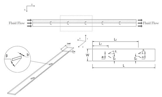
2.1. Physical and Computational Model

Three-dimensional simulations were performed on five different configurations of a microchannel with rectangular winglet-type LVGs to examine the impact of using nanofluids on the conjugate heat transfer characteristics and flow field. Figure 1 shows the dimensions of the physical model with the relevant parameters of the microchannels while the geometry parameters for the different configurations are presented in detail in Table 1. All parameters in Table 1 are related to H, (H = 1), which is the height of the microchannel. LVGs are used in CFD (common flow down) for an arrangement with 30° and CFU (common flow up) for arrangement with 150°. The fluid flow was described by the Cartesian coordinate system in which the Z-axis direction is the stream-wise direction. The simulation consists of two parts, where the first part contains a microchannel with two pairs of LVGs, which are located in the heated region. The second part is a microchannel, including the adiabatic walls with the same weight of the original one but without VGs and its length is where it is used to develop a fully developed flow for the outlet while the velocity boundary condition on the inlet was set as a fully developed velocity profile.
Because of symmetric arrangements of the microchannel and LVGs, only the hatched region that is shown in Figure 1 was included in the numerical simulations in order to decrease the computational time and costs.

2.2. Mathematical Models, Boundary Conditions and Governing Equations

The analysis presented in this study was performed on microchannel equipped with LVGs made of silicon, a conductive material, and based on the following assumptions:
  • The flow is considered as three dimensional, incompressible, hydraulically fully developed, steady and laminar due to the low velocity of the fluid and small pitch of the winglet.
  • The effects of radiation, gravity, body forces, viscous dissipation [1] and surface roughness are neglected [46].
  • Working fluids were selected from different nanofluids with low volume-fraction and different sizes of Al2O3 or CuO nanoparticles dispersed in pure water, POA and ethylene glycol as base fluids.
  • A single-phase model was used to effectively describe the heat transfer behavior of nanofluids and validated based on low concentration of nanoparticles with diameters smaller than 100 nm [47].
  • LVG was generated based on the quasi-steady phenomenon as reported by Ferrouillat et al. [48].
  • The coolant considered to be Newtonian and the thermophysical properties are dependent on the temperature, volume fraction and size of nanoparticles.
Based on the previous assumptions, the equations for steady-state flow of continuity, momentum and energy can be expressed as follows [49]:
. ( ρ n f . V m ) = 0
. ( ρ n f . V m . V m ) = p + . ( μ n f V m )
. ( ρ n f . c p . V m . T ) = ( k n f . T )
The energy equation for the solid zone is expressed as:
2 T s = 0
As depicted in Figure 1, the boundary conditions are:
  • At the inlet: the velocity is fully developed.
    T i n = 298   K   a t   x = 0 , u z = 0 , w = v = 0
  • At the outlet:
    d T f d x = 0 , u x = v y = w z
  • No-slip boundary condition is applied at the top, bottom and side walls as
    u = w = v = 0
  • Bottom and side walls are considered as adiabatic walls:
    T z | z = H = 0 , T z | y = 0 = 0
  • At the top surface, a uniform temperature is applied as
    T = T s = 323.15 [ K ]
  • The conjugate heat transfer between LVG surfaces (solid) and nanofluid is applied as
    k s ( T n ) | f = k s ( T n ) | s         and         T s = T f
    where n is a normal vector on the LVGs surface pointed out of the boundary.
  • Symmetry plane
    T x = T s x = 0 ,   u = 0
Table 2 shows the thermo-physical properties of pure water, POA, ethylene glycol, silicon, Al2O3 and CuO nanoparticles. The nanofluids’ effective thermophysical properties are calculated using the correlations illustrated below.
By the use of the mixture model approach the density of the nanofluid can be calculated as follows [50]:
ρ n f = ( 1 φ ) ρ b f + φ ρ n
By taking the energy balance between the base fluid and nanoparticles the specific heat of nanofluid can be determined as
c p , n f = ( 1 φ ) ( ρ c p ) b f + φ ( ρ c p ) n ( 1 φ ) ρ b f + φ ρ n
Both dynamic viscosity and the effective thermal conductivity of nanofluids are determined by using a model developed by Koo and Kleinstreuer [57], which takes into consideration the effects of particle size, Brownian motion and particle volume fraction with different types of base fluid and nanoparticle combinations. This model is valid for a temperature range between 300 K and 325 K, while the volume fraction is up to 4% [16].
k n f = k s t a t i c + k B r o w n i a n
where k s t a t i c can be optioned from Maxwell’s model and k B r o w n i a n is developed based on both kinetic theory and micromixing method as shown in the relationship below [58]:
k s t a t i c k b f = 1 + 3 × ( k n k b f 1 ) φ ( k n k b f + 2 ) ( k n k b f 1 ) φ
k B r o w n i a n = 5 × 1 0 4 φ c p , b f ρ b f k b T d n ρ n g ( T , φ , d n )
R f + d n k n = d n k n
where R f is Kapitza resistance, which equals to 4 × 10 8 km 2 / W .
By using the same approach, the effective viscosity of nanofluids can be predicted as follows:
μ n f = μ s t a t i c + μ B r o w n i a n
μ s t a t i c = μ b f ( 1 φ ) 2.5
μ B r o w n i a n = 5 × 1 0 4 φ ρ b f k b T d n ρ n g ( T , φ , d n )
where g function is a function that considered the effects of particle diameter, temperature and volume fraction. For various based fluids and nanoparticles, the relation for Al2O3–water nanofluids and CuO–water nanofluids based on the experimental data with regression values of 98% and 96%, respectively, are shown below [59]:
g = [ a + b l n ( d n ) + c l n ( φ ) + d l n ( φ ) l n ( d n ) + e l n ( d n ) 2 ] l n ( T ) + [ m + h l n ( d n ) + i l n ( φ ) + j l n ( d n ) l n ( φ ) + k l n ( d n ) 2 ]
where a, b, c, d, e, m, h, I, j and k are coefficients related to the type of based fluid and nanoparticle.

2.3. Numerical Procedures and Parameter Definitions

Commercial software for computational fluid dynamics ANSYS Fluent Software Release 16.0 was used to perform the simulations. Using ANSYS Meshing the meshes of the non-uniform grid for the computational domains. The grid generation of the model is shown in details in Figure 2 and Figure 3. The COUPLED algorithm was used for the pressure–velocity coupling based on the following reasons: First, by using it the approximations associated were eliminated in comparison to the segregated solution method, such as SIMPLE and SIMPLEC. Secondly, it reduces the errors that caused and related to physical model nonlinearities, the initial conditions and meshes that have been stretched and skewed [60]. The solution converges when the residual values are less than 10−6 for the momentum equation, 10−6 for the continuity equation and 10−8 for the energy equation.
The following parameters are defined to make a framework for the numerical results of this study.
  • Reynolds number:
    R e = ρ V i n D h μ
    where
    D h = 2 W . H W + H
  • j-Colburn factor:
    j = h ρ V m c p P r 2 3
    where Prandtl number
    P r = c p μ k
  • Convective heat transfer coefficient:
    h = Q T w a l l Δ T
    Δ T = ( T w a l l T i n ) ( T w a l l T o u t ) l n [ ( T w a l l T i n ) ( T w a l l T o u t ) ]
  • Total heat rate:
    Q = m ˙ c p ( T o u t T i n )
  • Nusselt number:
    N u = h D h k
  • Heat transfer performance factor:
    J = N u R e . P r 1 3
  • Fanning friction factor:
    f = 2 Δ p ρ V i n 2 × D h L
    where
    Δ p = ( p i n p o u t )
  • Overall thermal-hydraulic performance [61,62,63,64]:
    J F = j f 3
  • Thermal–hydraulic performance of the system [65,66,67]:
    η = ( N u N u 0 ) ( f 0 f ) 1 3

3. Grid Independency and Model Validation

In order to keep the simulation accurate with reasonable computational costs, a grid independence test was performed on four grids with different sizes as shown in Table 3. The tests were performed on A1 configuration with β1, β2 angle of 30° each using pure water as a working fluid under Re = 800. It can be seen from the result shown in Table 3 that there is a small difference between (490198) grid and (931236) grid in the computed results which was 0.038 and 0.034, respectively, hence the (490198) grid was selected for further simulations. The results were validated based on the experimental results presented by Liu et al. [25]. They used in their study deionized water was a working fluid with Reynolds number in the range of 170 to 1200. The bottom wall of the microchannel was maintained at a constant temperature of 323 K. Figure 4 and Figure 5 illustrate a comparison between Nu and f values from the present numerical simulation and the experimental results of Liu et al. [25]. It can be seen from these figures that the maximum and minimum deviations were 11.5% and 3.8%, respectively, for the Nu values while the maximum and minimum deviations were 13.34% and 2.7%, respectively, for the values of friction factor. Liu et al. [25] reported that the average uncertainties are caused by the equipment that has been used in determining the Nu number for the microchannel with and without LVGs is 19.6% and 12.8%, respectively.

4. Results and Discussions

The numerical computations were conducted for five different geometrical configurations on the thermo–hydraulic performance of microchannels with VGs and compared to the smooth microchannels using an Al2O3–water nanofluid as a working fluid. In this case, the effects of the nanofluids with different nanoparticle types (Al2O3 and CuO) and different base fluid (water, PAO and ethanol glycol) with a nanoparticles volume fraction of 2% and various nanoparticles diameters (29 nm and 28.6 nm) were tested using A1 configuration and compared to pure water. The effects of different geometry configurations and Reynolds numbers on the temperature and velocity distributions, Nusselt number, fanning friction coefficient and JF performance factor for different Reynolds numbers are interpreted and presented in this section.

4.1. The Effect of Different Geometry Configurations

The temperature distribution on different cross-sections along the stream-wise direction for A1 configurations at Re = 800 is shown in Figure 6. It is observed that the interactions between the working fluid and hot surfaces and longitudinal vortex generator cause a change in the temperature distribution. By increasing the Reynolds number, the thermal boundary layer on the microchannel walls and the area near the sides of longitudinal vortex generator gets thinner causing more change in temperature distribution. The higher temperature gradients that led to a higher heat transfer rate were caused by longitudinal and horseshoe vortices generated by the longitudinal vortex generator and the decrease in thermal boundary-layer thickness. It is also observed that by increasing the Reynolds numbers the temperature difference between the working fluid and hot surfaces gets higher, which causes a higher heat transfer rate. This can be explained that the forced convection becomes more dominant over the diffusive of heat transfer by increasing the Reynolds numbers, and vice versa [5,26]. Additionally, the area of the vortex generator is too low than the overall heat transfer surface and, therefore, the main reason to enhance the heat transfer is due to the increase in the convective heat transfer coefficient by flow distortion (secondary flow).
Figure 7 shows the flow pattern behind the VG at Re = 1100. The temperature distribution for different configurations at different Reynolds numbers with Al2O3–water as a working fluid is shown in Figure 8. It shows clearly that for all configurations the vortices were generated in the area behind the longitudinal vortex generator. Two different zones of high temperature occurred along the lateral side of the longitudinal vortex generator. The vortices generated by the vortex generator start to cause the two high-temperature zones to merge together and gradually starts to spread in a region close to the heated wall. The longitudinal vortex generator causes an up-wash and a down-wash in the area behind it. The up-wash and a down-wash flows have dual effects: (i) The downwash flow causes the hotter fluid near the heated wall moves at the central region, which leads to a decrease in the thickness of the thermal boundary layer. (ii) The up-wash flow causes the cooler fluid to be transferred from the central region to the heated wall, which causes an increase in the thickness of the thermal boundary layer; that explains why the temperature gradient gets higher near the walls [27].
Figure 9 illustrates the velocity distribution for A1 configuration at various Reynolds numbers with Al2O3–water as a nanofluid. It is noticed that a zone of high-velocity forms in the area between the longitudinal vortex generator and near the walls of the microchannel. The recirculation regions are also formed in the area behind the longitudinal vortex generator, which increases with the increase in Reynolds number. Furthermore, it is observed that the mixing of fluid becomes more intense with an increase in Reynolds number, and because of the shear layer generated behind the longitudinal vortex generator, an interaction between the vortices occurs; that causes the vortices to become more intense with the increase in Reynolds number. At higher Reynolds numbers, the flow covers longer distances going through a wavy path downstream of the longitudinal vortex generator; that is one of the reasons behind the enhancement in heat transfer by using a longitudinal vortex generator.
The Nusselt number and Fanning friction factor variations for different configurations for various Reynolds numbers using Al2O3–water as a working fluid are presented in Figure 10. It can be obviously seen that the Nusselt number for different configurations of the microchannels with a longitudinal vortex generator is greater than the plain microchannels in all ranges of the Reynolds numbers. It is found that the Nusselt number improved by 0.9%–28.1%. It is also noticed that when Reynolds number increases the Nusselt number increases as well. This can be explained as follows: By increasing the Reynolds number, the vortices become more powerful, which augment the fluid mixing and boost the swirl. It is observed that when the Re number reaches approximately 800, a rapid change in Nusselt number for A1 starts to occur. It can be explained that the longitudinal vortex generator with an acute angle of attack on the first row induces more powerful vortices in comparison to the ones with the obtuse angle of attack. As the Reynolds number increases, the vortices generated in the microchannel become stronger, which causes the decrease in thermal boundary thickness and increase in flow disturbance which improves the swirl in the microchannel.
As shown in Figure 10, microchannels with longitudinal vortex generators have better thermal performance, but it is associated with a pressure drop along the channel. The pressure drop may be caused by the presence of secondary flow and the interaction that happened between the vortices and the microchannel walls. It is also found that A1 configuration has the lowest friction factor among all other configurations while other configurations have almost the same friction factor in the considered Reynolds numbers range of this study. In general, the longitudinal vortex generator causes the frictional resistance of the channel walls to increase, due to more pressure drag brought by it [27].
The JF factor gives an evaluation of the overall thermal–hydraulic performance, which indicates the best performance of heat transfer related to the pressure drop. Figure 11 shows the JF values for different configurations for various Reynolds numbers by using CuO–Water as a working fluid. The results indicate that the A1 configuration has the highest JF factor values while other configurations have almost the same the JF factor values in Reynolds numbers range considered for this study.

4.2. The Effect of the Different Working Fluids

Based on the best configuration obtained from the previous section, different types of nanoparticles (Al2O3 and CuO) dispersed in different types of base fluid (water, PAO and ethanol glycol) with the nanoparticles volume fraction of 2% and various nanoparticles diameters (29 nm and 28.6 nm) are applied to the A1 configuration. This microchannel with a longitudinal vortex generator has better thermal performance, but it is associated with a pressure drop along the channel. The aim of this section is to determine the nanofluid with the best thermal–hydraulic performance.
Figure 12 demonstrates the effect of changing nanoparticle material on the Nu number and Fanning friction factor for a range of Reynolds numbers and the particle diameter of 29 nm and 28.6 nm. It can be clearly seen that there is a directly proportional relation between Nu number and Re number for all working fluids in the present study. It can be explained that nanofluids have greater heat absorption and the use of metallic nanoparticles increases the thermal conductivity of the mixture, with a larger heat transfer surface area, and thus increases the collision rate of the nanoparticles that increases the nanoparticles’ Brownian motion [45]. The increase in thermal conductivity leads to intensive energy transfer, which dominates the diffusion in the working fluid and causes greater bulk temperatures. It is found that CuO–water shows a greater increase in heat transfer compared to Al2O3–water at the same volume fraction and Reynolds numbers; that can be attributed to the fact that CuO nanoparticles have higher thermal conductivity with the comparison to Al2O3 nanoparticles as well as by the effects of the alignment, structure and interactions of the nanoparticles [49].
Based on Figure 12, the enhancement of heat transfer performance comes with the increase in Fanning friction factor; that can be explained as nanofluids have higher viscosity if compared with its base-fluid. Furthermore, at a higher volume fraction, the powerful hydrodynamic interactions between the nanoparticles cause an increase in nanofluids viscosity. Figure 12 depicts at the same Reynolds numbers and volume fraction, that CuO–water nanofluids have a higher Fanning friction factor in comparison to Al2O3–water nanofluids. As the Reynolds number increases, the µBrownian gets lower while µstatic gets higher. If it is compared with pure water, this relative increase in nanofluid viscosity gets higher at lower Re number leading to further increase in Fanning friction factor at constant volume fraction; that causes the need for more pumping power to drive nanofluids inside the microchannels [35].
Figure 13 shows the effect of base fluid material on the Nu number and Fanning friction factor for a range of Reynolds numbers and the particle diameter of 29 nm. As shown in Figure 10, in the range of Re number between 200 and 600, it is revealed that the CuO–PAO nanofluid has a higher Nu number among another nanofluid in the scope of the study. But, in the range of Re between 600 and 1200, the Nusselt number for CuO–PAO starts to decrease while CuO–water maintains an increase in Nusselt number. With the increase of Re number the CuO–water takes the lead from CuO–PAO. In all ranges of Re number, CuO–water and EG have the lowest Nusselt numbers among all nanofluids used in this study. Regarding the Fanning friction factor, in the same range of Re number between 200 and 400, almost all base fluids have a higher Fanning friction factor compared to water. In the Re number range of study, CuO–PAO has the lowest Fanning friction factor while CuO–W:EG has the highest Fanning friction factor; that can be explained in that PAO has a low viscosity compared to ethylene glycol, which makes CuO–PAO have a lower Fanning friction factor than CuO–W:EG [40]. It is also shown that CuO–PAO has lower pressure drop than CuO–water, which can be explained that the PAO could have a lubrication effect that reduces the pressure drop along the microchannels.
As shown in Figure 14, the results indicate that Al2O3–water nanofluid has the highest JF factor compared with another nanofluid in the considered Reynolds numbers range; that indicates that Al2O3–water has the best performance in terms of high Nusselt number with a low friction factor among all nanofluids. With regard to the base fluid, the results revealed that CuO–PAO has the highest JF factor in the range of Re number between 200 and 1000, but in a high Reynolds number range between 100 and 1200 the JF factor decreases, which make the CuO–water nanofluid to have the highest JF factor as shown in Figure 15. In almost all the range of Reynolds number in the present study, CuO–water has an increase with respect to the increase in Reynolds number while CuO–W:EG keeps having the lowest JF factor values.
The use of nanofluids as working fluids in microchannels with longitudinal vortex generators cause an observable enhancement in overall thermal performance. Figure 16 represents the summary of thermal performance percentage of the A1 configuration microchannels with various nanofluids for different Reynolds numbers. According to Figure 16, the higher overall thermal performance is observed for the CuO–PAO, CuO–water and Al2O3–water nanofluid, in an ascending order. Furthermore, across the range of Reynolds numbers used in the present study CuO–W:EG showed the lowest overall thermal performance. The CuO–PAO shows the best overall performance because it is due to the highest Nu number and lowest friction factor. It is worthy to mention that the oil in the POA reduced the pressure drop in the channel and the CuO particle increased the thermal properties of the oil, which increased the Nu number. According to previous result, the proposed CuO–PAO nanofluid has a promising solution to solve the problem of a high pressure drop in the microchannel since it also has one of the lowest Fanning frictions due to the lubrication effect of its base fluid.

5. Conclusions

This paper has presented a numerical investigation on the thermo-hydraulic performance of a three-dimensional rectangular microchannel with longitudinal vortex generators. The flow was assumed to be steady-state, single-phase, laminar flow. The study consisted of two parts: First, the effects of five different geometrical configurations on the thermo-hydraulic performance of the microchannels with VGs were studied and compared with the smooth microchannels, using the Al2O3–water nanofluid as a working fluid. Second, the effects of the nanofluids with different nanoparticle types (Al2O3 and CuO) and different base fluid (water, PAO and ethanol glycol) with a nanoparticle volume fraction of 2% and various nanoparticles diameters (29 nm and 28.6 nm) applied into the A1 configuration were studied and compared to pure water. The simulations were performed using a CFD code and the results were validated based on the experimental and numerical data leading to the following remarkable conclusions:
  • The assessment of thermal and hydraulic performance on various LVG configurations shows A1 to be the best configuration for LVG arrangement, and after that A2, A4 and A3 are in the list, respectively. The augmentation in Nusselt number was 0.9%–28.1% using the Al2O3–water nanofluid. However, it comes with the penalty of increasing the Fanning friction factor by 5.2%–28% for the Al2O3–water nanofluid with respect to the smooth microchannel.
  • In case of different base fluids, CuO–PAO has the best performance. The Nusselt number values were 7.67–14.7 and 9.57–15.88, respectively, for Al2O3–water and CuO–PAO, with the penalty of increasing the Fanning friction factor by 5%–33.6% and 4.2%–26%, respectively, for Al2O3–water and CuO–PAO.
This device is mainly designed for chip cooling. So, it is recommended to use this technique under high flowrates in order to achieve a higher overall efficiency. Further investigations can be done on various other nano microchannel heat management applications, such as Bio-MEMS in nano drug delivery.

Author Contributions

Conceptualization, B.A.M., and M.A.W.; Methodology, H.A.M. and M.K.; Software, B.A.M.; Validation, B.A.M., and H.A.M.; Formal analysis, B.A.M., M.A.W., and H.A.M.; Investigation, B.A.M., M.K., and D.H.; Resources, M.K., and D.H.; Writing—original draft preparation, B.A.M., and H.A.M.; Writing—review and editing, B.A.M., H.A.M., and D.H.; Supervision, M.A.W., M.K., and D.H. All authors have read and agreed to the published version of the manuscript.

Funding

This research received no external funding.

Conflicts of Interest

The authors declare no conflict of interest.

References

  1. Tuckerman, D.; Pease, R. IIIB-8 implications of high-performance heat sinking for electron devices. IEEE Trans. Electron Devices 1981, 28, 1230–1231. [Google Scholar] [CrossRef]
  2. Adham, A.M.; Mohd-Ghazali, N.; Ahmad, R. Thermal and hydrodynamic analysis of microchannel heat sinks: A review. Renew. Sustain. Energy Rev. 2013, 21, 614–622. [Google Scholar] [CrossRef]
  3. Agostini, B.; Fabbri, M.; Park, J.E.; Wojtan, L.; Thome, J.R.; Michel, B. State of the art of high heat flux cooling technologies. Heat Transf. Eng. 2007, 28, 258–281. [Google Scholar] [CrossRef]
  4. Morini, G.L. Single-phase convective heat transfer in microchannels: A review of experimental results. Int. J. Therm. Sci. 2004, 43, 631–651. [Google Scholar] [CrossRef]
  5. Koyuncuoğlu, A.; Jafari, R.; Okutucu-Özyurt, T.; Külah, H. Heat transfer and pressure drop experiments on CMOS compatible microchannel heat sinks for monolithic chip cooling applications. Int. J. Therm. Sci. 2012, 56, 77–85. [Google Scholar] [CrossRef]
  6. Xu, B.; Ooti, K.; Wong, N.; Choi, W. Experimental investigation of flow friction for liquid flow in microchannels. Int. Commun. Heat Mass Transf. 2000, 27, 1165–1176. [Google Scholar] [CrossRef]
  7. Qu, W.; Mudawar, I. Experimental and numerical study of pressure drop and heat transfer in a single-phase micro-channel heat sink. Int. J. Heat Mass Transf. 2002, 45, 2549–2565. [Google Scholar] [CrossRef]
  8. Harms, T.M.; Kazmierczak, M.J.; Gerner, F.M. Developing convective heat transfer in deep rectangular microchannels. Int. J. Heat Fluid Flow 1999, 20, 149–157. [Google Scholar] [CrossRef]
  9. Tuckerman, D.B.; Pease, R.F.W. High-performance heat sinking for VLSI. IEEE Electron Device Lett. 1981, 2, 126–129. [Google Scholar] [CrossRef]
  10. Xia, G.; Zhai, Y.; Cui, Z. Numerical investigation of thermal enhancement in a micro heat sink with fan-shaped reentrant cavities and internal ribs. Appl. Therm. Eng. 2013, 58, 52–60. [Google Scholar] [CrossRef]
  11. Xia, G.; Jiang, J.; Wang, J.; Zhai, Y.; Ma, D. Effects of different geometric structures on fluid flow and heat transfer performance in microchannel heat sinks. Int. J. Heat Mass Transf. 2015, 80, 439–447. [Google Scholar] [CrossRef]
  12. Fiebig, M. Vortices and heat transfer. Zamm J. Appl. Math. Mech. 1997, 77, 3–18. [Google Scholar] [CrossRef]
  13. Ahmed, H.; Mohammed, H.; Yusoff, M. An overview on heat transfer augmentation using vortex generators and nanofluids: Approaches and applications. Renew. Sustain. Energy Rev. 2012, 16, 5951–5993. [Google Scholar] [CrossRef]
  14. Sohankar, A. Heat transfer augmentation in a rectangular channel with a vee-shaped vortex generator. Int. J. Heat Fluid Flow 2007, 28, 306–317. [Google Scholar] [CrossRef]
  15. Tian, L.-T.; He, Y.-L.; Lei, Y.-G.; Tao, W.-Q. Numerical study of fluid flow and heat transfer in a flat-plate channel with longitudinal vortex generators by applying field synergy principle analysis. Int. Commun. Heat Mass Transf. 2009, 36, 111–120. [Google Scholar] [CrossRef]
  16. Fiebig, M. Embedded vortices in internal flow: Heat transfer and pressure loss enhancement. Int. J. Heat Fluid Flow 1995, 16, 376–388. [Google Scholar] [CrossRef]
  17. Biswas, G.; Chattopadhyay, H.; Sinha, A. Augmentation of heat transfer by creation of streamwise longitudinal vortices using vortex generators. Heat Transf. Eng. 2012, 33, 406–424. [Google Scholar] [CrossRef]
  18. Yadav, V.; Baghel, K.; Kumar, R.; Kadam, S. Numerical investigation of heat transfer in extended surface microchannels. Int. J. Heat Mass Transf. 2016, 93, 612–622. [Google Scholar] [CrossRef]
  19. Fiebig, M.; Kallweit, P.; Mitra, N.; Tiggelbeck, S. Heat transfer enhancement and drag by longitudinal vortex generators in channel flow. Exp. Therm. Fluid Sci. 1991, 4, 103–114. [Google Scholar] [CrossRef]
  20. Davidson, A.S.L. Effect of inclined vortex generators on heat transfer enhancement in a three-dimensional channel. Numer. Heat Transf. Part A Appl. 2001, 39, 433–448. [Google Scholar] [CrossRef]
  21. Mohammed, H.; Al-Shamani, A.; Sheriff, J. Thermal and hydraulic characteristics of turbulent nanofluids flow in a rib–groove channel. Int. Commun. Heat Mass Transf. 2012, 39, 1584–1594. [Google Scholar] [CrossRef]
  22. Islam, M.S.; Hino, R.; Haga, K.; Monde, M.; Sudo, Y. Experimental study on heat transfer augmentation for high heat flux removal in rib-roughened narrow channels. J. Nucl. Sci. Technol. 1998, 35, 671–678. [Google Scholar] [CrossRef]
  23. Leu, J.-S.; Wu, Y.-H.; Jang, J.-Y. Heat transfer and fluid flow analysis in plate-fin and tube heat exchangers with a pair of block shape vortex generators. Int. J. Heat Mass Transf. 2004, 47, 4327–4338. [Google Scholar] [CrossRef]
  24. Wu, J.; Tao, W. Numerical study on laminar convection heat transfer in a rectangular channel with longitudinal vortex generator. Part A: Verification of field synergy principle. Int. J. Heat Mass Transf. 2008, 51, 1179–1191. [Google Scholar] [CrossRef]
  25. Liu, C.; Teng, J.-t.; Chu, J.-C.; Chiu, Y.-l.; Huang, S.; Jin, S.; Dang, T.; Greif, R.; Pan, H.-H. Experimental investigations on liquid flow and heat transfer in rectangular microchannel with longitudinal vortex generators. Int. J. Heat Mass Transf. 2011, 54, 3069–3080. [Google Scholar] [CrossRef]
  26. Chen, C.; Teng, J.-T.; Cheng, C.-H.; Jin, S.; Huang, S.; Liu, C.; Lee, M.-T.; Pan, H.-H.; Greif, R. A study on fluid flow and heat transfer in rectangular microchannels with various longitudinal vortex generators. Int. J. Heat Mass Transf. 2014, 69, 203–214. [Google Scholar] [CrossRef]
  27. Salleh, M.F.M.; Mohammed, H.A.; Wahid, M.A. Thermal and hydraulic characteristics of trapezoidal winglet across fin-and-tube heat exchanger (FTHE). Appl. Therm. Eng. 2019, 149, 1379–1393. [Google Scholar] [CrossRef]
  28. Li, Z.; Xu, X.; Li, K.; Chen, Y.; Huang, G.; Chen, C.-l.; Chen, C.-H. A flapping vortex generator for heat transfer enhancement in a rectangular airside fin. Int. J. Heat Mass Transf. 2018, 118, 1340–1356. [Google Scholar] [CrossRef]
  29. Ebrahimi, A.; Roohi, E.; Kheradmand, S. Numerical study of liquid flow and heat transfer in rectangular microchannel with longitudinal vortex generators. Appl. Therm. Eng. 2015, 78, 576–583. [Google Scholar] [CrossRef] [Green Version]
  30. Xie, Y.; Zheng, L.; Zhang, D.; Xie, G. Entropy generation and heat transfer performances of Al2O3-water nanofluid transitional flow in rectangular channels with dimples and protrusions. Entropy 2016, 18, 148. [Google Scholar] [CrossRef] [Green Version]
  31. Ebrahimi, A.; Rikhtegar, F.; Sabaghan, A.; Roohi, E. Heat transfer and entropy generation in a microchannel with longitudinal vortex generators using nanofluids. Energy 2016, 101, 190–201. [Google Scholar] [CrossRef]
  32. Choi, S.; Singer, D.; Wang, H. Developments and applications of non-Newtonian flows. Asme Fed 1995, 66, 99–105. [Google Scholar]
  33. Hamilton, R.L.; Crosser, O. Thermal conductivity of heterogeneous two-component systems. Ind. Eng. Chem. Fundam. 1962, 1, 187–191. [Google Scholar] [CrossRef]
  34. Brinkman, H. The viscosity of concentrated suspensions and solutions. J. Chem. Phys. 1952, 20, 571. [Google Scholar] [CrossRef]
  35. Corcione, M. Heat transfer features of buoyancy-driven nanofluids inside rectangular enclosures differentially heated at the sidewalls. Int. J. Therm. Sci. 2010, 49, 1536–1546. [Google Scholar] [CrossRef]
  36. Maxwell, J.C. 4 Treatise on Electricity and Magnetism, 2nd ed.; Clarendon Press: Oxford, UK, 1881; Volume 1, p. 435ff. [Google Scholar]
  37. Bruggeman, V.D. Berechnung verschiedener physikalischer Konstanten von heterogenen Substanzen. I. Dielektrizitätskonstanten und Leitfähigkeiten der Mischkörper aus isotropen Substanzen. Ann. Der Phys. 1935, 416, 636–664. [Google Scholar] [CrossRef]
  38. Yu, W.; Choi, S. The role of interfacial layers in the enhanced thermal conductivity of nanofluids: A renovated Maxwell model. J. Nanopart. Res. 2003, 5, 167–171. [Google Scholar] [CrossRef]
  39. Machrafi, H.; Lebon, G. The role of several heat transfer mechanisms on the enhancement of thermal conductivity in nanofluids. Contin. Mech. Thermodyn. 2016, 28, 1461–1475. [Google Scholar] [CrossRef]
  40. Shaikh, S.; Lafdi, K.; Ponnappan, R. Thermal conductivity improvement in carbon nanoparticle doped PAO oil: An experimental study. J. Appl. Phys. 2007, 101, 064302. [Google Scholar] [CrossRef] [Green Version]
  41. Lee, S.; Choi, S.-S.; Li, S.; Eastman, J. Measuring thermal conductivity of fluids containing oxide nanoparticles. J. Heat Transf. 1999, 121, 280–289. [Google Scholar] [CrossRef]
  42. Suresh, S.; Chandrasekar, M.; Sekhar, S.C. Experimental studies on heat transfer and friction factor characteristics of CuO/water nanofluid under turbulent flow in a helically dimpled tube. Exp. Therm. Fluid Sci. 2011, 35, 542–549. [Google Scholar] [CrossRef]
  43. Kalteh, M.; Abbassi, A.; Saffar-Avval, M.; Harting, J. Eulerian–Eulerian two-phase numerical simulation of nanofluid laminar forced convection in a microchannel. Int. J. Heat Fluid Flow 2011, 32, 107–116. [Google Scholar] [CrossRef]
  44. Gavili, A.; Isfahani, T.D.; Zabihi, F.; Hadi, I. The effect of real viscosity on the heat transfer of water based Al2O3 nanofluids in a two-sided lid-driven differentially heated rectangular cavity. Heat Mass Transf. 2013, 49, 1433–1445. [Google Scholar] [CrossRef]
  45. Kalteh, M.; Abbassi, A.; Saffar-Avval, M.; Frijns, A.; Darhuber, A.; Harting, J. Experimental and numerical investigation of nanofluid forced convection inside a wide microchannel heat sink. Appl. Therm. Eng. 2012, 36, 260–268. [Google Scholar] [CrossRef]
  46. Li, P.; Zhang, D.; Xie, Y. Heat transfer and flow analysis of Al2O3–water nanofluids in microchannel with dimple and protrusion. Int. J. Heat Mass Transf. 2014, 73, 456–467. [Google Scholar] [CrossRef]
  47. Seyf, H.R.; Feizbakhshi, M. Computational analysis of nanofluid effects on convective heat transfer enhancement of micro-pin-fin heat sinks. Int. J. Therm. Sci. 2012, 58, 168–179. [Google Scholar] [CrossRef]
  48. Ferrouillat, S.; Tochon, P.; Garnier, C.; Peerhossaini, H. Intensification of heat-transfer and mixing in multifunctional heat exchangers by artificially generated streamwise vorticity. Appl. Therm. Eng. 2006, 26, 1820–1829. [Google Scholar] [CrossRef] [Green Version]
  49. Ghale, Z.Y.; Haghshenasfard, M.; Esfahany, M.N. Investigation of nanofluids heat transfer in a ribbed microchannel heat sink using single-phase and multiphase CFD models. Int. Commun. Heat Mass Transf. 2015, 68, 122–129. [Google Scholar] [CrossRef]
  50. Pak, B.C.; Cho, Y.I. Hydrodynamic and heat transfer study of dispersed fluids with submicron metallic oxide particles. Exp. Heat Transf. Int. J. 1998, 11, 151–170. [Google Scholar] [CrossRef]
  51. Glassbrenner, C.; Slack, G.A. Thermal conductivity of silicon and germanium from 3 K to the melting point. Phys. Rev. 1964, 134, A1058. [Google Scholar] [CrossRef]
  52. Bergman, T.L.; Lavine, A.S.; Incropera, F.P.; Dewitt, D.P. Fundamentals of Heat and Mass Transfer; John Wiley Sons Inc.: Hoboken, NJ, USA, 2011. [Google Scholar]
  53. Etminan-Farooji, V.; Ebrahimnia-Bajestan, E.; Niazmand, H.; Wongwises, S. Unconfined laminar nanofluid flow and heat transfer around a square cylinder. Int. J. Heat Mass Transf. 2012, 55, 1475–1485. [Google Scholar] [CrossRef]
  54. Yue, Y.; Mohammadian, S.K.; Zhang, Y. Analysis of performances of a manifold microchannel heat sink with nanofluids. Int. J. Therm. Sci. 2015, 89, 305–313. [Google Scholar] [CrossRef]
  55. Liu, K. Heat Transfer Measurement in Oil-Based Nanofluids. Ph.D. Thesis, University of Louisville, Louisville, KY, USA, 2011; p. 841. [Google Scholar]
  56. E.G.P. MEGlobal Guide. 2008. Available online: https://www.meglobal.biz/wp-content/uploads/2019/01/Monoethylene-Glycol-MEG-Technical-Product-Brochure-PDF.pdf (accessed on 10 February 2020).
  57. Koo, J.; Kleinstreuer, C. A new thermal conductivity model for nanofluids. J. Nanopart. Res. 2004, 6, 577–588. [Google Scholar] [CrossRef]
  58. Li, J.; Kleinstreuer, C. Thermal performance of nanofluid flow in microchannels. Int. J. Heat Fluid Flow 2008, 29, 1221–1232. [Google Scholar] [CrossRef]
  59. Li, J. Computational Analysis of Nanofluid Flow in Microchannels with Applications to Micro-Heat Sinks and Bio-MEMS. Ph.D. Thesis, North Carolina State University, Raleigh, NC, USA, 2008. [Google Scholar]
  60. ANSYS Inc. ANSYS Fluent Theory Guide. 2013. Available online: https://www.academia.edu/38091499/ANSYS_Fluent_Theory_Guide (accessed on 10 February 2020).
  61. Wu, X.; Zhang, W.; Gou, Q.; Luo, Z.; Lu, Y. Numerical simulation of heat transfer and fluid flow characteristics of composite fin. Int. J. Heat Mass Transf. 2014, 75, 414–424. [Google Scholar] [CrossRef]
  62. Li, J.; Wang, S.; Chen, J.; Lei, Y.-G. Numerical study on a slit fin-and-tube heat exchanger with longitudinal vortex generators. Int. J. Heat Mass Transf. 2011, 54, 1743–1751. [Google Scholar] [CrossRef]
  63. Wu, X.; Liu, D.; Zhao, M.; Lu, Y.; Song, X. The optimization of fin-tube heat exchanger with longitudinal vortex generators using response surface approximation and genetic algorithm. Heat Mass Transf. 2016, 52, 1871–1879. [Google Scholar] [CrossRef]
  64. Gholami, A.A.; Wahid, M.A.; Mohammed, H.A. Heat transfer enhancement and pressure drop for fin-and-tube compact heat exchangers with wavy rectangular winglet-type vortex generators. Int. Commun. Heat Mass Transf. 2014, 54, 132–140. [Google Scholar] [CrossRef]
  65. Ahmed, H.E.; Mohammed, H.A.; Yusoff, M.Z. Heat transfer enhancement of laminar nanofluids flow in a triangular duct using vortex generators. Superlattices Microstruct. 2012, 52, 398–415. [Google Scholar] [CrossRef]
  66. Gholami, A.A.; Mohammed, H.A.; Wahid, M.A.; Khiadani, M. Parametric design exploration of fin-and-oval tube compact heat exchangers performance with a new type of corrugated fin patterns. Int. J. Therm. Sci. 2019, 144, 173–190. [Google Scholar] [CrossRef]
  67. Gholami, A.A.; Wahid, M.A.; Mohammed, H.A. Thermal-hydraulic performance of fin-and-oval tube compact heat exchangers with innovative design of corrugated fin patterns. Int. J. Heat Mass Transf. 2017, 106, 573–592. [Google Scholar] [CrossRef]
Figure 1. The physical model and the computational domain.
Processes 08 00231 g001
Figure 2. The grid generation of the computational model.
Processes 08 00231 g002
Figure 3. Close-up look for the grid near to the LVG refinement.
Processes 08 00231 g003
Figure 4. Comparison of Nu number values from the present numerical simulation and the experimental results of Liu et al. [25].
Processes 08 00231 g004
Figure 5. Comparison of friction factor values from the present numerical simulation and the experimental results of Liu et al. [25].
Processes 08 00231 g005
Figure 6. (a) Temperature distribution on different cross-sections along the stream-wise direction for A1 configurations at Re = 800; (b) cross-sections positions along the microchannel.
Processes 08 00231 g006
Figure 7. Flow pattern behind the VG at Re =1100.
Processes 08 00231 g007
Figure 8. Isotherms for A1 configurations at (a) Re = 200, (b) Re=600 and (c) Re= 1200.
Processes 08 00231 g008
Figure 9. Streamlines for various configurations of a microchannel at Re =700 for (a) A1, (b) A2, (c) A3 and (d) A4.
Processes 08 00231 g009
Figure 10. Nusselt number and Fanning friction factor versus Reynolds number for various microchannel configurations.
Processes 08 00231 g010
Figure 11. JF factor versus Reynolds number for various microchannel configurations.
Processes 08 00231 g011
Figure 12. Variation of Nusselt number and Fanning friction with Reynolds number for various nanoparticle material and Reynolds numbers.
Processes 08 00231 g012
Figure 13. The effect of base fluid material and Reynolds number on Nusselt number and Fanning friction factor.
Processes 08 00231 g013
Figure 14. The effect of different nanoparticles and Reynolds number on the JF factor.
Processes 08 00231 g014
Figure 15. The effect of various base fluids and Reynolds number on the JF factor.
Processes 08 00231 g015
Figure 16. Thermal performance of the A1 configuration microchannels with various nanofluids for different Reynolds numbers.
Processes 08 00231 g016
Table 1. List of various microchannel configurations.
Microchannel L 1 L 2 a 1 a 2 S 1 S 2 β 1 , β 2 b l
plain------- H 4 5H
A 1 50H100H4H4H8H8H30, 30 H 4 5H
A 2 50H100H4H4H8H8H150,150 H 4 5H
A 3 50H100H4H4H8H8H30, 150 H 4 5H
A 4 50H100H4H4H8H8H150, 30 H 4 5H
Table 2. Thermo-physical properties of pure water, POA, ethylene glycol, silicon, Al2O3 and CuO.
Silicon [51]Al2O3 [52] CuO [53]Pure-Water [54]POA [55]Ethylene Glycol [56]
µ (Pa.s) 2.761 × 10 6 exp ( 1713 T ) 873.61113
k (W/m.K)290 − 0.4 T3676.5 0.6 ( 1 + 4.167 × 10 5 T ) 0. 03050.00485
c p (J/kg.K)390 + 0.9 T765535.641801396 3216.6 + 3.489 × T
ρ (kg/m3)23303970635010002040 0.3896479 0.000102004 × T 0.000001543 × T 2
Table 3. Grid independence test results at Re = 800.
Number of CellsPredicted Nu % Diff %
I201,006 (coarse)8.3I vs. II2.47
II385,619 (intermediate)8.1II vs. III1.85
III490,198 (fine)7.9III vs. IV0.38
IV931,236 (very fine)7.87

