Article

Research on Rotordynamic Characteristics of Pump Annular Seals Based on a New Transient CFD Method

National-Provincial Joint Engineering Laboratory for Fluid Transmission System Technology, Zhejiang Sci-Tech University, Hangzhou 310018, China
*
Author to whom correspondence should be addressed.
Processes 2020, 8(2), 227; https://doi.org/10.3390/pr8020227
Submission received: 31 December 2019 / Revised: 11 February 2020 / Accepted: 12 February 2020 / Published: 15 February 2020
(This article belongs to the Special Issue Advancement in Computational Fluid Mechanics and Optimization Methods)

Abstract

:
Pump annular seals can cause fluid reaction forces that have great effects on the vibration characteristic and stability of a pump system. For this reason, it is important to study rotordynamic characteristics of annular seals. In this paper, a new transient computational fluid dynamics (CFD) method with dynamic mesh is proposed to investigate rotordynamic characteristics of the pump annular seal. The reliability of the transient CFD method is validated by comparison with the results from the experiment and the bulk-flow method, and the relationship between the seal length and rotordynamic characteristics is investigated by the transient CFD method. The results indicate that direct stiffness decreases sharply even turns to negative as the seal length increases, this phenomenon may change the direction of fluid force on the rotor surface and affect supporting condition of the pump rotor. With the increasing seal length, the whirl frequency ratio gradually increases, which would weaken the stability of the pump rotor system.

1. Introduction

Liquid annular seals are necessary components of pumps to control leakage flow, improve efficiency and balance axial thrust. Annular seals mainly include impeller wear rings, inter-stage seals and balancing drum gaps. The length of an impeller wear ring is short and the aspect ratio (L/D) is generally around 0.1. The aspect ratios of inter-stage seals and balancing drum gaps can reach up to 3. Just like journal bearings, small clearances, large axial pressure drops and shearing effects of pump rotors mean that annular seals have an important effect on the vibration and stability characteristics of a rotor system.
In view of the important influence of annular seals on vibration characteristics of pump systems [1], the bulk-flow method is commonly used in industry to study the dynamic characteristics of annular seals. The bulk-flow method is based on the thin film assumption in Hirs’ turbulent lubrication theory, which is actually a two-dimensional flow model as it ignores the radial gradients of flow variables. Childs [2] first achieved the finite length solutions of dynamic coefficients of annular seals based on the bulk-flow method. Then Dietzen et al. [3], Marquette et al. [4] and Sun et al. [5] used the bulk-flow method to investigate the static and dynamic characteristics of annular seals. However, the bulk-flow method lacks flow details and its accuracy largely depends on empirical correction coefficients such as friction factors that will change with seal geometry and operating conditions. With the development of computer technology, a CFD method [6] has been used as an effective method for predicting the leakage flow rates and rotordynamic characteristics of annular seals. Compared to the bulk-flow method, the CFD method is better at describing internal flow field, and is applicable for more complex sealing structures and operating conditions. Tam et al. [7] applied the quasi-steady CFD method to study fluid dynamic forces in seals and bearings. They assumed that the rotor performed the circle whirl motion around the seal center and solved the whirl flow field in the rotating frame of reference (RFR) attached to the rotor using the quasi-steady CFD simulation. Mortazavi [8] used the quasi-steady CFD method to predict the rotordynamic performance of the labyrinth seal and showed that the results from the CFD method are in good agreement with the experimental results. Because the quasi-steady CFD method can directly use the existing commercial CFD solver and has good generality for complex seals, it has been accepted and widely used by researchers [9,10,11,12,13,14,15]. Subsequently, a transient-state CFD method in which the rotor position is physically perturbed in a periodic whirling orbit using moving mesh techniques is proposed to deal with complex rotor motion. In this method, the time-varying fluid response forces on the rotor surface and the equivalent dynamic characteristics are obtained by integrating the pressure and shear stresses predicted in transient CFD solutions. Williams et al. [16] first used dynamic mesh movement algorithms and finite difference methods to solve the unsteady Navier–Stokes equations and obtained dynamic fluid forces in the annular seal. Jiang et al. [17] identified the difference between the quasi-steady CFD method and the transient CFD method in predicting the dynamic characteristics of liquid annular seals. The results showed that the transient CFD calculation predicted the mass coefficient very well but the quasi-steady CFD calculation under-predicted it by almost one half. Chochua et al. [18] applied a transient CFD method with a single-frequency one dimensional (1D) whirl orbit on annular hole-pattern gas seals to predict the frequency-dependent dynamic characteristics. The transient CFD method based on a 1D whirl model was also applied on honeycomb seals and labyrinth seals by other researchers [19,20]. These above transient CFD methods are all single-frequency whirl methods. In order to reduce calculation time, Li et al. [21] used a transient CFD method based on a multiple-frequency 1D whirl model for rotordynamic coefficients of pocket damper seals and then the author applied this method to labyrinth seals and hole-pattern seals based on a multiple-frequency elliptical whirl model [22]. Comparing the experimental data and the numerical simulation data demonstrated that the numerical method with the multiple-frequency elliptical whirl model is available for predicting rotordynamic coefficients of annular gas seals in turbomachinery. Yan et al. [23] also employed the multiple-frequency whirl model for predicting rotordynamic coefficients of hole-pattern seals. The author revealed that the computational time of the method is reduced significantly while the accuracy is still maintained. Jiang [24] and Wu et al. [25] performed transient simulations describing a variable-speed whirl motion to obtain dynamic characteristics of pump seals. The results showed that the method can keep the same accuracy as the single-frequency whirl method, while largely saving the computational time.
In the present paper, a new transient CFD method with dynamic mesh was used to investigate the rotordynamic characteristics of the pump annular seal. The prediction accuracy of the transient CFD method is compared with that of the bulk-flow method [26]. Dynamic characteristics of the seal with different lengths are also calculated by the transient CFD method. Direct stiffness, whirl-frequency ratio and static pressure distributions of the seal with different lengths are compared and the mechanism of seal length on the pump rotor system is explored.

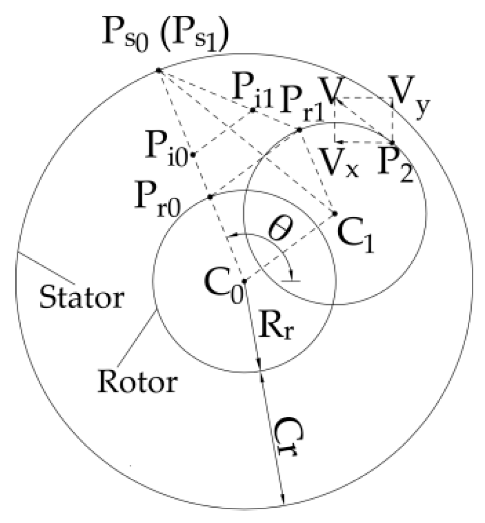
2. Method for Determining Rotordynamic Coefficients

As the rotor location changes with time in a rotor-stator system, a transient CFD simulation is applied to investigate the unsteady flow within a full 360-degree model of the seal. Before starting the transient simulation, the rotor is at the seal center as shown in Figure 1a. During the simulation, the rotor position is perturbed by using a circle orbit whirl model, and the maximum clearance and the minimum clearance will appear in the seal as shown in Figure 1b. The circle whirl model consists of two types of rotor whirling motions, one is forward whirling where the rotor whirls and rotates in the same direction, and the other is backward whirling where the rotor whirls and rotates in opposite directions. In this circle orbit whirling model, the moving displacements of the rotor in the x and y directions are given in Equation (1), where the amplitude e denotes the whirl radius.
{ x d =   ecos ( Ω t ) ,   y d =   esin ( Ω t ) ( Forward   whirl ) x d =   ecos ( Ω t ) ,   y d =   esin ( Ω t ) ( Backward   whirl )
During the transient computations, the fluid forces (Fx, Fy) acting on the rotor at each time step are captured by integrating the pressure and shear stresses. In order to quantify the fluid forces for small perturbation around a concentric rotor position, the conventional rotordynamic model is expressed in Equation (2) [2].
[ F x F y ] = [   K k   k K ] { x d y d } + [   C c   c   C ] { x d ˙ y d ˙ } + [ M 0   0   M ] { x d ¨ y d ¨ }
where K and k are direct and cross stiffness coefficients, respectively; C and c are direct and cross damping coefficients, respectively; and M is a direct mass coefficient. According to the relationship between (Fx, Fy) and (Fr, Ft), the dynamic coefficients can be expressed as Equation (3).
{ F r / e   =   K c Ω + M Ω 2 F t / e   =   k C Ω

3. Numerical Investigation

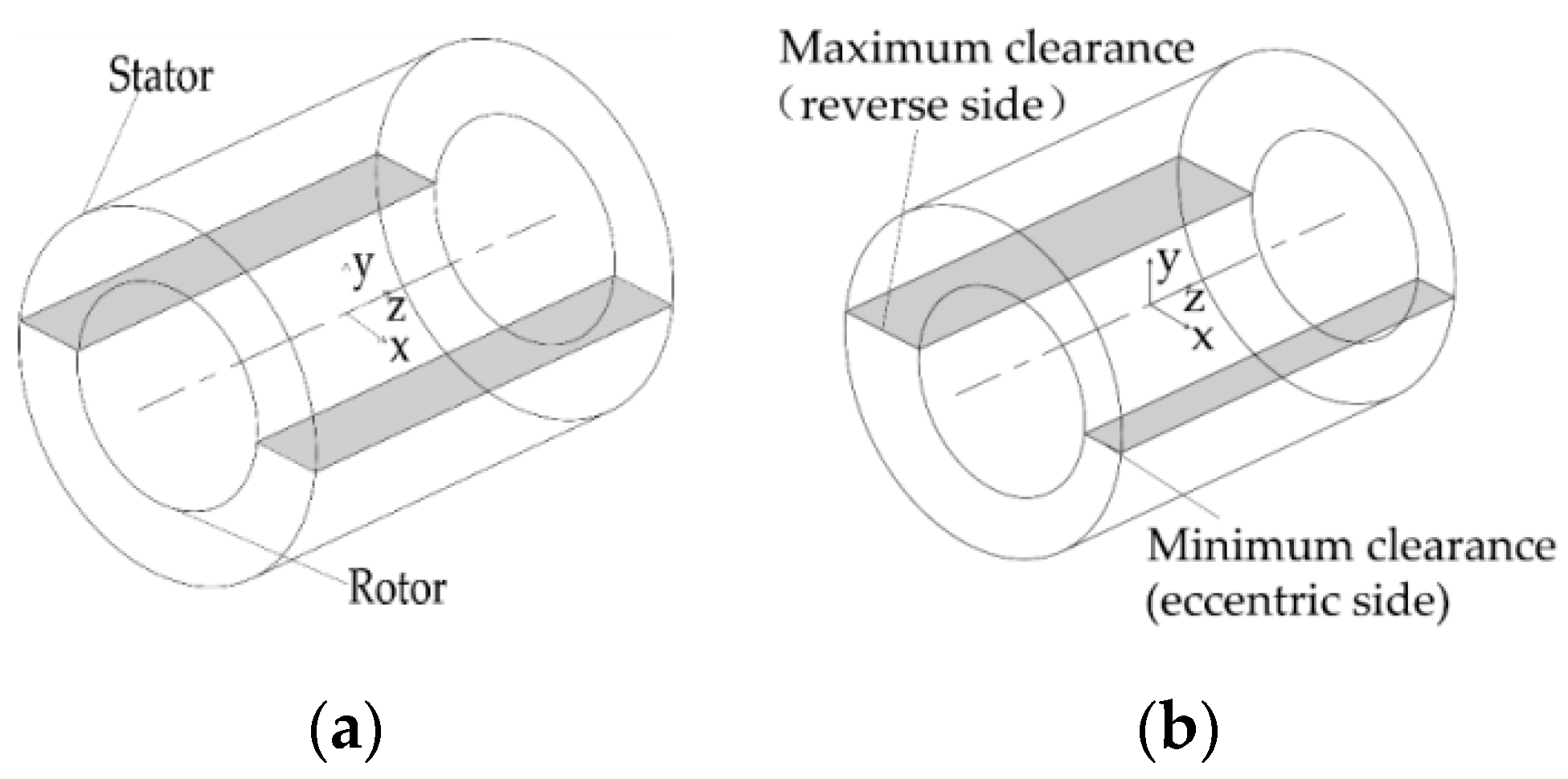
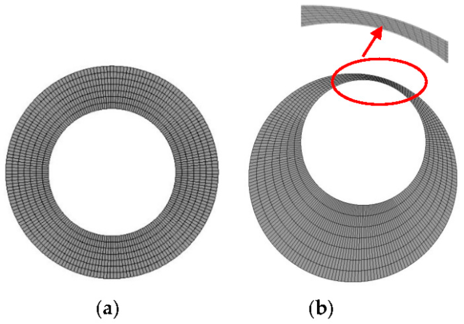
3.1. Geometry Model and Grid

The annular seal used in the present study is shown in Figure 2a, and the main geometric parameters and operating conditions are shown in Table 1. The generated grid can be seen in Figure 2b. The whole flow field of the seal is meshed with structured hexahedral grids and the grid independence investigation under different operating pressures is carried out. Figure 3 shows the grid independence investigation result under the pressure of 1.38 MPa. It is found that the leakage remains almost constant when the mesh number reaches approximately 0.425 million. Therefore, the mesh used in this paper is composed of 424,960 nodes and 364,980 cells.

3.2. Mesh Movement

Due to the circle orbit whirl model of the rotor as mentioned in Section 2, the shape of the fluid domain changes with time, which needs a transient CFD method to deal with it. To perform the transient CFD computations, the dynamic mesh problem should be solved. In this work, the dynamic mesh is achieved by applying a user-defined subroutine linked with FLUENT solver to strictly control the motion of every grid node in the seal model. The specific implementation procedures are as follows.
Figure 4 shows a cross-section view of a simplified plain seal at an arbitrary axial position. As illustrated in the figure, the seal clearance Cr has been exaggerated, C1 represents the current eccentric position where the rotor moves from concentric position marked C0, d (xd, yd, 0) denotes the moving distance of the rotor in Cartesian coordinates. When the rotor is at the concentric position, Pi0 represents an arbitrary node in the clearance of the seal and is assumed to project along a mesh line that connects one node Pr0 on the rotor surface and another Ps0 on the stator surface. After the rotor moves by d, the movement displacements of the nodes on the rotor surface are also d. Therefore, the new coordinates (xr1, yr1) of Pr0 are defined as Equation (4).
  x r 1 =   x r 0 + x d ,   y r 1 =   y r 0 + y d
where xr0, yr0 are x and y coordinates of Pr0 when the rotor is at the concentric position. The nodes of the stator surface stay still, and the movement distances of the nodes between the rotor and the stator are determined by the interpolation algorithm [24] as shown in Equation (5a). Therefore, the new position coordinates (xi1, yi1) of Pi0 are transformed using Equation (5b)
x d i 1 =   ra × x d ,   y d i 1 =   ra × y d
{ x i 1 =   x i 0 + x d i 1   =   x i 0 + ra × x d y i 1 =   y i 0 + y d i 1   =   y i 0 + ra × y d
where xi0, yi0 are x and y coordinates of Pi0 when the rotor is at the concentric position. In Equation (5a), ra represents the ratio of the distance between the nodes in the clearance and the outer wall to the clearance. When the rotor is in the concentric and eccentric positions, ra can be expressed as Equation (6)
ra = { ( R r + C r ) ( x i 0 ) 2 + ( y i 0 ) 2 C r ( Concentric   position ) [ x i 1 ( R r + C r ) cos θ ] 2 + [ y i 1 ( R r + C r ) s sin θ ] 2 ( x d C r cos θ ) 2 + ( y d C r sin θ ) 2 ( Eccentric   position )
where θ denotes the initial angular coordinate of the node Pi0 as shown in Figure 4. By Equation (7), θ is expressed as Equation (8). Substituting Equation (8) into Equation (6) and then substituting Equation (6) into Equation (5b) gives new positions of the nodes in clearances after the rotor moves.
{ p s 1 p i 1 = [ x i 1 ( R r + C r ) cos θ , y i 1 ( R r + Cr ) sin θ )   p s 1 p r 1 = [ ( R r cos θ + x d ( R r + C r ) cos θ ) ,   ( R r sin θ + y d ( R r + Cr ) sin θ ) ] ( x i 1 ( R r + C r ) cos θ ) ( y d C r sin θ ) = ( y i 1 ( R r + Cr ) sin θ ) ( x d C r cos θ )
θ = { arcsin [ y i 1 x d x i 1 y d [ ( R r + C r ) x d x i 1 C r ] 2 + [ y i 1 C r ( R r + C r ) y d ] 2 ] arctan y i 1 C r ( R r + C r ) y d ( R r + C r ) x d x i 1 C r π arcsin [ y i 1 x d x i 1 y d [ ( R r + C r ) x d x i 1 C r ] 2 + [ y i 1 C r ( R r + C r ) y d ] 2 ] arctan y i 1 C r ( R r + C r ) y d ( R r + C r ) x d x i 1 C r
By adopting the dynamic mesh algorithm, the displacement of each grid node is strictly calculated by the mathematical procedures to ensure the movement coordination of adjacent grid nodes. The algorithm has been tested and found that when the rotor whirled from the concentric position as shown in Figure 5a to the eccentric position with an amplitude of 90% seal clearance as shown in Figure 5b, the maximum skewness of the grids increases from 0.065 to 0.46. The grid skewness becomes larger, which means that when the rotor whirls with a big eccentricity, the grid distortion rate will increase (grid skewness ranges from 0 to 1, where the value is close to 1, which corresponds to low quality). However, the grids in the clearance still do not appear as highly distorted elements and negative volumes, which indicates that the dynamic mesh algorithm is applicable for transient flow simulations of the seal. During the rotor whirling, the locus of the rotor center changes with time so that the rotational speed of the rotor cannot be set by traditional methods. The DEFINE macro DEFINE_PROFILE is applied to read the coordinates of the rotor grids, which change according to the instantaneous position of the rotor. Tangential velocity in the surface of the rotor is divided into two component velocities as given in Equation (9), which are given to the surface nodes of the rotor by the DEFINE macro [27].
{ v x =   ( y p 2 y c 1 ) × ω v y =   ( x p 2 x c 1 ) × ω
where vx, vy are velocities in the x and y directions of an arbitrary grid node of P2, and ω is the rotational speed of the rotor.

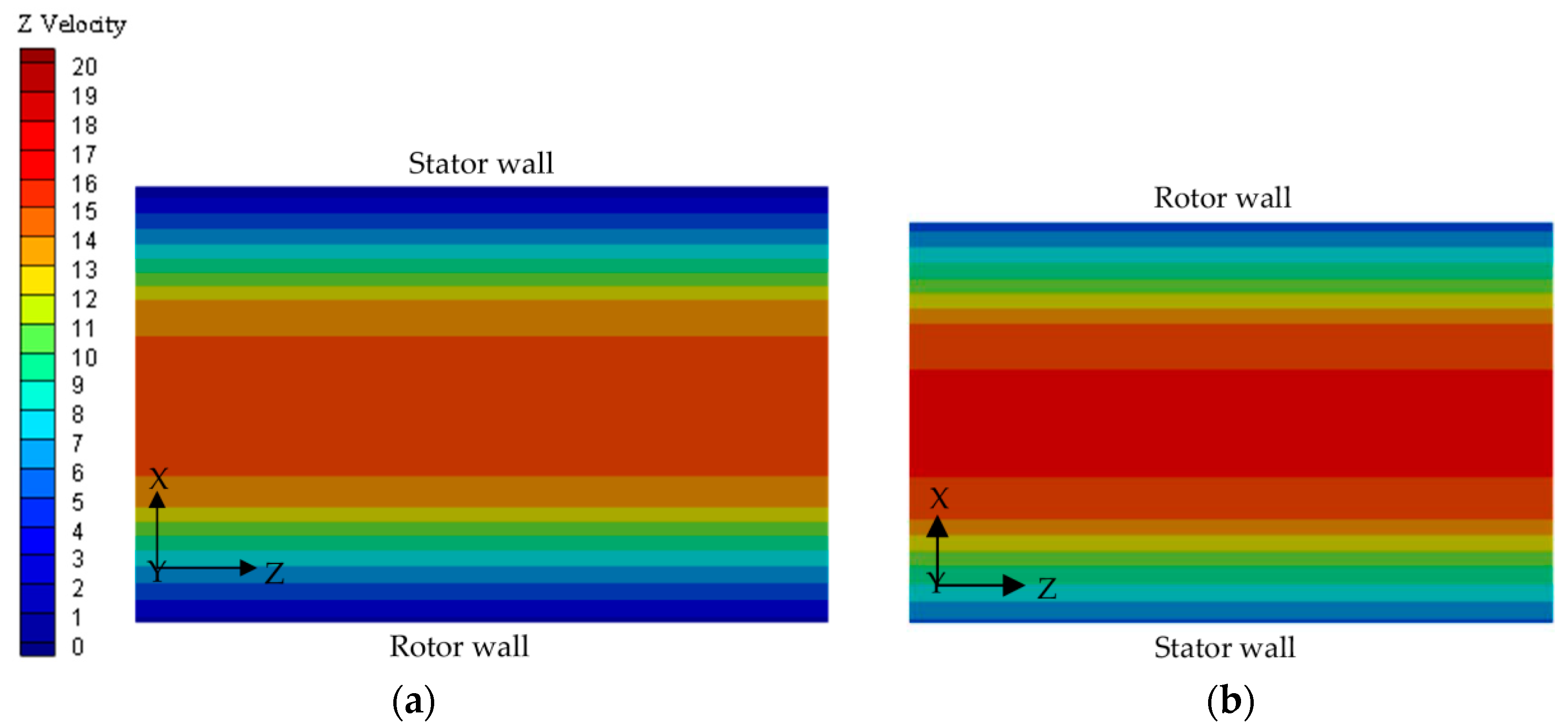
3.3. 3D Transient Analysis and Verification

3.3.1. Numerical Method

The commercial code FLUENT16.0 is employed to solve the three-dimensional incompressible Navier–Stokes equations. Figure 6 shows the flow chart for the calculation of unsteady CFD. A steady-state CFD solution is initially solved to obtain the initial conditions of the unsteady CFD calculation. In the unsteady CFD calculation, the rotational speed of the rotor is defined by Define macro Define_ profile, and the whirling speed of the rotor is loaded by user-defined function. The inlet boundary is set as total pressure and the outlet boundary is set as static pressure. Nonslip boundary conditions are used for the near-wall function. The realizable k-ε model and the enhanced wall function are chosen according to the wall Y+, which is located in the range of 20–40 [17]. The size of the time step is 1.634E-5s, i.e., the time spent by the rotor in one degree rotation. The whirl radius e is 0.0076 mm, which is selected as 10% of the radial clearance. Second-order, upwind discretization has been used for the convection and central difference schemes for diffusion terms. The SIMPLE algorithm is used to deal with the pressure-velocity coupling.

3.3.2. Fluid Reaction Forces

Figure 7 shows the calculated reaction forces acting on the rotor respectively with forward and backward whirl motion models under three pressure differences. It can be seen from the figure that the fluid forces of forward and backward whirls show similar periodic behaviors. The fluid reaction forces increase as the pressure difference increases, and the force Fx in the X direction is slightly larger than the force Fy in the Y direction. The maximum forces of Fx are 42.5, 65.9 and 85.8 N and the maximum forces of Fy are 36.8, 59.7 and 82.7 N, when the operating pressure differences are 1.38, 2.41 and 3.45 MPa for operating under the forward whirl. The maximum forces of Fx are 38.6, 61.7 and 81.7 N and the maximum forces of Fy are 36.6, 57.6 and 79.6 N, when the pressure differences are 1.38, 2.41 and 3.45 MPa for operating under the backward whirl. For the forward whirl motion model, the phase of Fx is ahead of that of Fy with a phase difference of 80°. While for the backward whirl motion model, the phase of Fx is behind of that of Fy with a phase difference of 102°.

3.3.3. Theoretical and Experimental Verification

The calculation results based on the proposed method are compared to the results based on the bulk-flow method and the experimental results. Figure 8a shows direct stiffness changes with respect to the pressure differences. As illustrated in the figure, the maximum error of predicted direct stiffness K under three pressure differences based on the transient CFD method is less than 20%, while the maximum error of K from the bulk-flow method is almost up to 40%. The result of K from the transient CFD method shows better correlation with the experimental result in comparison to the result from the bulk-flow method. Figure 8b shows cross coupled stiffness k. The results of the transient CFD method and the bulk-flow method are all larger than the experimental one. The errors of the transient CFD method from 1.38 MPa to 3.45 MPa are approximately 29%, 26% and 32% respectively. However, the errors of bulk-flow analysis under corresponding pressure differences are about 38%, 42% and 29% respectively, which yield a worse prediction. Figure 8c shows direct damping C. The experimental result shows that the errors of the transient CFD method and the bulk-flow method for C are about 4~10% and 4~19%, respectively. The leakage of the seal is obtained by integrating the Z-directional flow velocity with respect to the cross section of the seal inlet and is shown in Figure 9. The results from the CFD simulation and bulk-flow method are respectively 16% and 22% of the experimental results. Therefore, the transient CFD analysis provides better improvements than the analysis taken from the bulk-flow method. The listed comparisons show that the transient CFD method proposed in this paper can significantly improve the prediction accuracy of leakage rates and dynamic characteristics of annular seals.

4. Results and Discussion

The length of the seal has a great effect on dynamic characteristics, especially direct stiffness. The length of the seal was changed from 13.13 mm (L/D = 0.17) to 91.44 mm (L/D = 1.2) with other boundary conditions maintained in order to investigate the relationship between the length and dynamic characteristics. The results of dynamic characteristics were obtained by using the transient CFD method, as shown in Table 2. Figure 10 shows the relationship between direct stiffness and the seal length. It can be seen that direct stiffness changes from positive to negative as the seal length increases and a critical length exists where direct stiffness is zero. In the present study, the critical points are at the length of 50.05 mm, 63.24 mm and 74.32 mm, when the pressure differences are 1.38, 2.41 and 3.45 MPa. This phenomenon is mainly caused by inlet loss and the change of the static pressure distribution in the flow channel of the clearances. Figure 11 shows that axial velocity in the eccentric side (minimum clearance) is smaller than that in the reverse side (maximum clearance). Luis [28] pointed out that a small clearance has a smaller axial velocity and lower inlet loss, which would bring higher static pressure to the eccentric side of the seal than that in the reverse side, thus creating a fluid reaction force to push the rotor to the seal center. This phenomenon is known as Lomakin effects, which can produce positive direct stiffness. Chen [29] explained that inlet loss is the main cause for Lomakin effects. So if the seal is not long enough to ignore the influence of inlet flow, a positive direct stiffness can be obtained. However, static pressure in the eccentric side of the seal is lower than that in the reverse side due to higher velocity in the eccentric side as shown in Figure 12 when the seal is long enough to ignore the influence of inlet flow. Therefore, direct stiffness of the long seal can be negative.
Figure 13 shows the distribution of static pressure on the rotor face with different seal lengths for Ω/ω = 0. Lx is the axial position and L is the seal length. Lx/L = 0 and Lx/L = 1 denote the position of seal inlet and outlet, respectively. The red circles in Figure 13 represent cross points, which indicate the axial position where the static pressure of the eccentric side equals that of the reverse side. Static pressure of the axial position before the cross point is consistent with Lomakin effects, while after the cross point is consistent with Bernoulli effects. For the short seals as shown in Figure 13a,b, static pressures of the eccentric side and the reverse side show an almost linear reduction across the seal length, and a cross point on the axial position does not exist in the short seal. Static pressure in the eccentric side is indeed larger than that in the reverse side, especially at a larger pressure difference, which is in line with Lomakin effects, and its direct stiffness is positive. For the long seals as shown in Figure 13c,d, static pressure on both sides also decreases in the direction of the leak and a cross point appears in the axial position at three pressure differences, where Bernoulli effects play a dominant role in the seal. This is due to inlet flow gradually stabilizing as the seal length increases so that the influence of inlet flow becomes weak and makes Bernoulli effects become noticeable, which corresponds to negative direct stiffness.
The whirl-frequency ratio f is introduced as Equation (10) [30] to weigh the effect of the seal length on the stability of the pump rotor system
f = k C Ω
From Figure 14, the whirl-frequency ratio generally increases with the increasing seal length, due to the influence of cross-coupled stiffness. As the seal length increases to 91.44 mm, the whirl-frequency ratios are nearly up to 0.47 when the seal operates under three pressure differences. This phenomenon means that the long seal would reduce stability of the rotor system.

5. Conclusions

In this paper, the transient CFD method with dynamic mesh was used to predict dynamic characteristics of the pump annular seal. The following conclusions can be made.
(1)
The proposed transient CFD method can control the grid movement at each time step and achieve optimal grid quality of the displacement grid at any time step. The CFD results were compared with the results from the experiment and the bulk-flow method. It was shown that the transient CFD analysis can provide better improvements than the bulk-flow analysis. The dynamic characteristics of annular seals can be predicted accurately by the transient CFD method.
(2)
The relationship between the seal length and rotordynamic characteristics was also investigated by the transient CFD method. The results show that direct stiffness changes from positive to negative as the seal length increases. This phenomenon can change the direction of the fluid force on the rotor surface and reduce the supporting effect of the annular seal on the pump rotor.
(3)
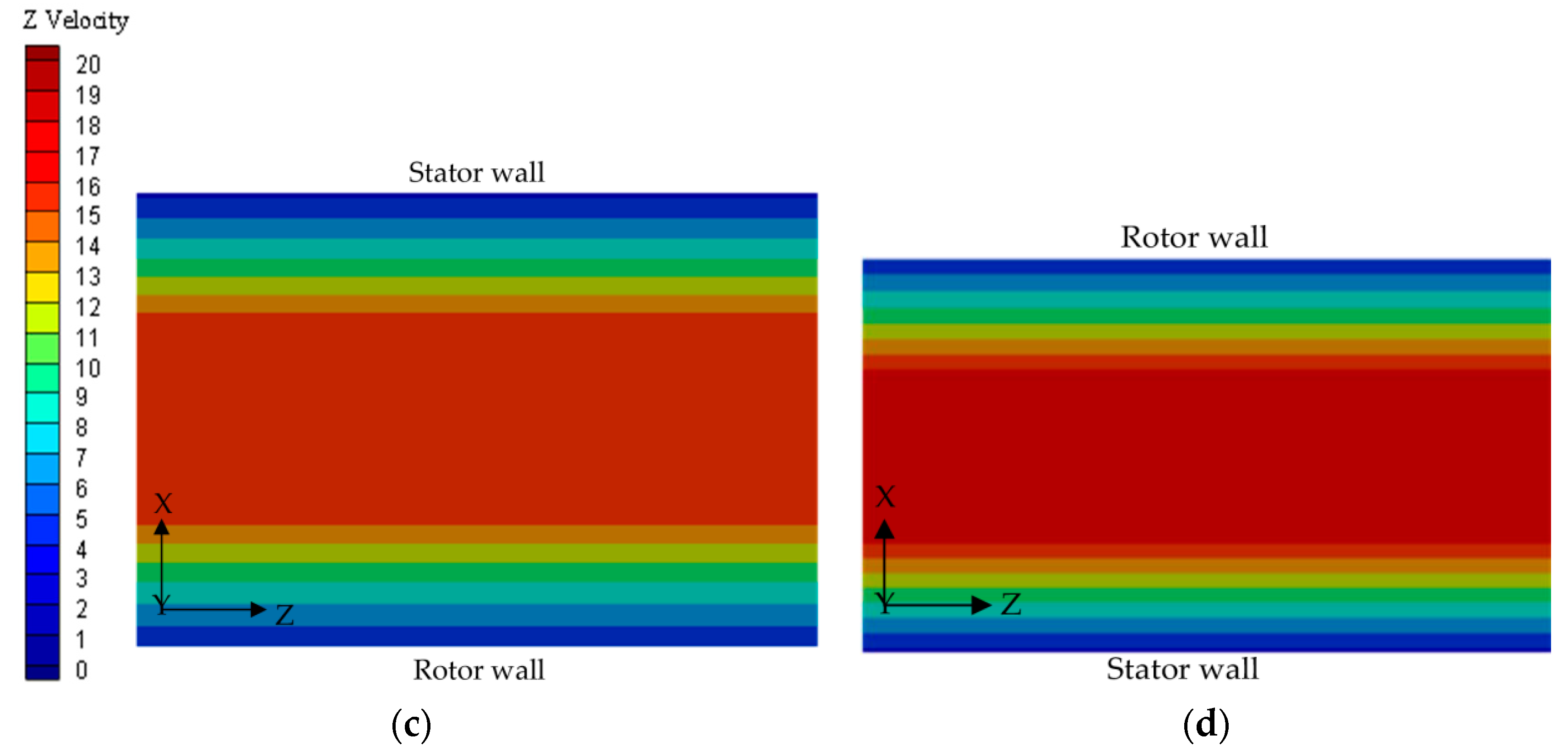
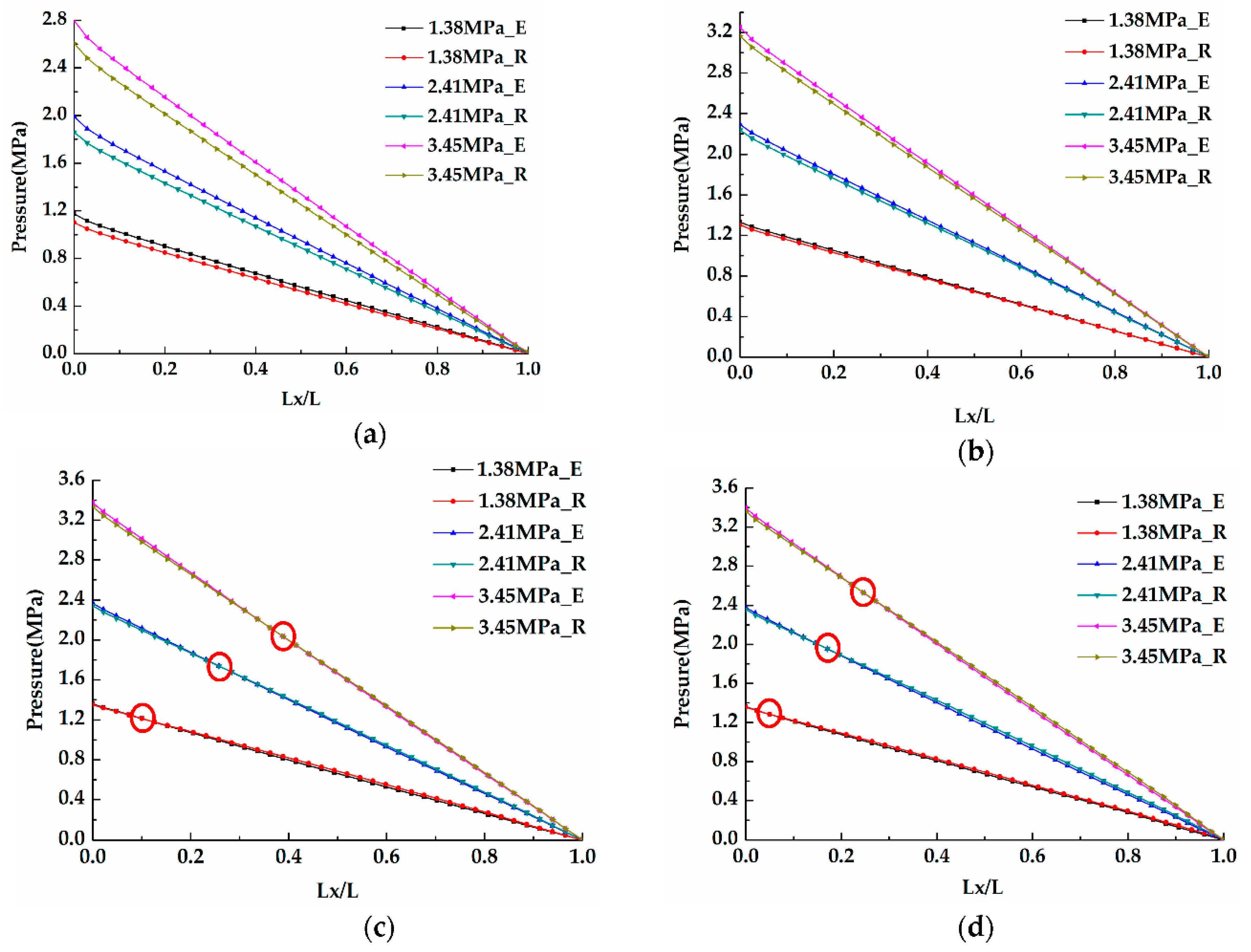
For the short seal, the static pressure of the eccentric side is almost larger than that of the reverse side and direct stiffness is positive. For the long seal, a cross point exists in the axial position that makes Bernoulli effects predominant and direct stiffness negative. With the increasing seal length, the whirl-frequency ratio becomes larger, which decreases the stability of the pump rotor system.

Author Contributions

Conceptualization, L.Z.; methodology, L.Z. and F.L.; validation, B.C., formal analysis, F.L.; writing—original draft preparation, F.L.; writing—review and editing, F.L. All authors have read and agreed to the published version of the manuscript.

Funding

This research was funded by the National Natural Science Foundation of China (Grant No. 51606170), Joint Project from National Natural Science Foundation of China and Liaoning Province (Grant No. U1608258). Zhejiang Provincial Natural Science Foundation of China (Grant No. LZ20E060002). Zhejiang Province Public Welfare Technology Research Project (Grant No. LGG18E060007).

Conflicts of Interest

The authors declare no conflict of interest.

Nomenclature

DSeal diameter [mm]
LSeal length [mm]
CrSeal clearance [mm]
eWhirl radius [mm]
ωRotor velocity [rpm]
ΩWhirl velocity [mm]
PDPressure difference [MPa]
θInitial angular of Pi0 [rad]
RrRotor radius [mm]
KDirect stiffness [N/m]
kCross coupled stiffness [N/m]
CDirect damping [Ns/m]
cCross coupled damping [Ns/m]
MInertia mass [kg]
fWhirl frequency ratio

References

  1. Wang, C.; Chen, X.; Qiu, N.; Zhu, Y.; Shi, W. Numerical and experimental study on the pressure fluctuation, vibration, and noise of multistage pump with radial diffuser. J. Braz. Soc. Mech. Sci. Eng. 2018, 40, 481. [Google Scholar] [CrossRef]
  2. Childs, D.W. Turbomachinery Rotordynamics: Phenomena, Modeling and Analysis; Wiley-Interscience: New York, NY, USA, 1993; pp. 229–243. [Google Scholar]
  3. Dietzen, F.J.; Nordmann, R. Calculating Rotordynamic Coefficients of Seals by Finite-Difference Techniques. J. Tribol. 1987, 109, 388–394. [Google Scholar] [CrossRef] [Green Version]
  4. Marquette, O.R.; Childs, D.W. An Extended Three-Control-Volume Theory for Circumferentially-Grooved Liquid Seals. J. Tribol. 1996, 118, 276–284. [Google Scholar] [CrossRef]
  5. Sun, D.; Yang, J.; Guo, R.; Zhang, W.; Ai, Y. A Trigonometric Series Expansion Based Method for the Research of Static and Dynamic Characteristics of Eccentric Seals. J. Mech. Sci. Technol. 2014, 28, 2111–2120. [Google Scholar] [CrossRef]
  6. Wang, C.; He, X.; Cheng, L.; Luo, C.; Xu, J.; Chen, K.; Jiao, W. Numerical Simulation on Hydraulic Characteristics of Nozzle in Waterjet Propulsion System. Processes 2019, 7, 915. [Google Scholar] [CrossRef] [Green Version]
  7. Tam, L.T.; Przekwas, A.J.; Muszynska, A.; Hendricks, R.C.; Braun, M.J.; Mullen, R.L. Numerical and Analytical Study of Fluid Dynamic Forces in Seals and Bearings. J. Vib. Acoust. 1988, 110, 315–325. [Google Scholar] [CrossRef]
  8. Mortazavi, F.; Palazzolo, A. Prediction of Rotordynamic Performance of Smooth Stator-Grooved Rotor Liquid Annular Seals Utilizing Computational Fluid Dynamics. J. Vib. Acoust. 2018, 140, 031002. [Google Scholar] [CrossRef]
  9. Ha, T.W.; Choe, B.S. Numerical Prediction of Rotordynamic Coefficients for an Annular-Type Plain-Gas Seal Using 3D CFD Analysis. J. Mech. Sci. Technol. 2014, 28, 505–511. [Google Scholar] [CrossRef]
  10. Ha, T.W.; Choe, B.S. Numerical Simulation of Rotordynamic Coefficients for Eccentric Annular-Type-Plain-Pump Seal Using CFD Analysis. J. Mech. Sci. Technol. 2012, 26, 1043–1048. [Google Scholar] [CrossRef]
  11. Moore, J.J. Three-Dimensional CFD Rotordynamic Analysis of Gas Labyrinth Seals. J. Vib. Acoust. 2003, 125, 427–433. [Google Scholar] [CrossRef]
  12. Untaroiu, A.; Hayrapetian, V.; Untaroiu, C.D.; Wood, H.G.; Schiavello, B.; McGuire, J. On the Dynamic Properties of Pump Liquid Seals. J. Fluids Eng. 2013, 135, 051104. [Google Scholar] [CrossRef]
  13. Untaroiu, A.; Migliorini, P.; Wood, H.G.; Allaire, P.E.; Kocur, J.A. Hole-Pattern Seals: A Three Dimensional CFD Approach for Computing Rotordynamic Coefficient and Leakage Characteristics. In Proceedings of the ASME 2009 International Mechanical Engineering Congress and Exposition, Lake Buena Vista, FL, USA, 13–19 November 2009; pp. 981–990. [Google Scholar] [CrossRef]
  14. Subramanian, S.; Sekhar, A.; Prasad, B. Rotordynamic characteristics of rotating labyrinth gas turbine seal with centrifugal growth. Tribol. Int. 2016, 97, 349–359. [Google Scholar] [CrossRef]
  15. Moore, J.J.; Ransom, D.L.; Viana, F. Rotordynamic Force Prediction of Whirling Centrifugal Compressor Impellers Using Computational Fluid Dynamics. J. Eng. Gas Turbines Power 2010, 133, 042504. [Google Scholar] [CrossRef]
  16. Williams, M.; Chen, W.; Brozowski, L.; Eastland, A. Three-Dimensional Finite Difference Method for Rotordynamic Fluid Forces on Seals. AIAA J. 1997, 35, 1417–1420. [Google Scholar] [CrossRef]
  17. Jiang, X.K.; Wu, D.Z. Numerical Study of the Fluid Forces for a Whirling Annular Seal: CFD Simulation versus Experiment. In Proceedings of the 6th ISFMF, Wuhan, China, 22 October 2014; pp. 836–843. [Google Scholar] [CrossRef]
  18. Chochua, G.; Soulas, T.A. Numerical Modeling of Rotordynamic Coefficients for Deliberately Roughened Stator Gas Annular Seals. J. Tribol. 2007, 129, 424–429. [Google Scholar] [CrossRef]
  19. Nielsen, K.K.; Janck, K.; Underbakke, H. Hole-Pattern and Honeycomb Seal Rotordynamic Forces: Validation of CFD-based Prediction Techniques. J. Eng. Gas Turbine Power 2012, 7, 122505. [Google Scholar] [CrossRef]
  20. Sreedharan, S.S.; Vannini, G.; Mistry, H. CFD Assessment of Rotordynamic Coefficients in Labyrinth Seals. In Proceedings of the ASME Turbo Expo 2014: Turbine Technical Conference and Exposition, Düsseldorf, Germany, 16–20 June 2014; pp. 26999–27007. [Google Scholar] [CrossRef]
  21. Li, J.; Li, Z.G.; Feng, Z.P. Investigations on the Rotordynamic Coefficients of Pocket Damper Seals Using the Multifrequency, One- Dimensional, Whirling Orbit Model and RANS Solutions. J. Eng. Gas Turbines Power 2012, 134, 102510. [Google Scholar] [CrossRef]
  22. Li, Z.G.; Li, J.; Yan, X. Multiple Frequencies Elliptical Whirling Orbit Model and Transient RANS Solution Approach to Rotordynamic Coefficients of Annular Gas Seals Prediction. J. Vib. Acoust. 2013, 135, 031005. [Google Scholar] [CrossRef]
  23. Yan, X.; He, K.; Li, J.; Feng, Z.P. A Generalized Prediction Method for Rotordynamic Coefficients of Annular Gas Seals. J. Eng. Gas Turbines Power 2015, 137, 092506. [Google Scholar] [CrossRef]
  24. Jiang, X.K. Transient CFD Simulation on the Flow Field and Dynamic Characteristics of Annular Seals. Ph.D. Thesis, Zhejiang University, Hangzhou, China, 2016. [Google Scholar]
  25. Wu, D.; Jiang, X.K.; Li, S.; Wang, L.Q. A New Transient CFD Method for Determining the Dynamic Coefficients of Liquid Annular Seals. J. Mech, Sci. Technol. 2016, 30, 3477–3486. [Google Scholar] [CrossRef]
  26. Lindsey, W.T.; Childs, D.W. The Effect of Converging and Diverging Axial Taper on the Rotordynamic Coefficients of Liquid Annular Pressure Seals: Theory versus Experiment. J. Vib. Acoust. 2000, 122, 126–131. [Google Scholar] [CrossRef]
  27. ANSYS FLUENT 16.0 Theory Guide [CP/DK]; ANSYS Inc.: Canonsburg, PA, USA, 2011.
  28. Luis, S.A.; Lu, X.L.; Zhu, J. Leakage and Force Coefficients for Pump Annular Seals Operating with Air/Oil Mixtures: Measurements Vs Predictions and Air Injection to Increase Seal Dynamic Stiffness; Turbomachinery Laboratory, Texas A & M Engineering Experiment Station: College Station, TX, USA, 2018; Available online: http://hdl.handle.net/1969.1/175007 (accessed on 15 February 2020).
  29. Chen, J.C.; Gunter, E.J. Introduction to Dynamics of Rotor-Bearing Systems; Trafford Publishing: Victoria, BC, Canada, 2005; pp. 297–304. [Google Scholar]
  30. Lund, J.W. The Stability of an Elastic Rotor in Journal Bearings with Flexible, Damped Supports. J. Appl. Mech. 1965, 32, 911–920. [Google Scholar] [CrossRef]
Figure 1. The schematic diagram of the position between the rotor and the stator: (a) initial position of the rotor, (b) eccentric position of the rotor.
Processes 08 00227 g001
Figure 2. (a) Calculation domain and (b) grid.
Processes 08 00227 g002
Figure 3. Grid independency analysis.
Processes 08 00227 g003
Figure 4. Diagram of the grid nodes moving.
Processes 08 00227 g004
Figure 5. Front view of the meshed rotor: (a) initial grids, (b) moved grids.
Processes 08 00227 g005
Figure 6. Calculation flow chart of the proposed transient CFD method.
Processes 08 00227 g006
Figure 7. Reaction forces acting on the rotor as a function of time: (a) forward whirling, (b) backward whirling.
Processes 08 00227 g007
Figure 8. Rotordynamics coefficients as a function of pressure difference: (a) direct stiffness, (b) cross coupled stiffness, (c) direct damping.
Processes 08 00227 g008
Figure 9. Leakage as a function of pressure difference.
Processes 08 00227 g009
Figure 10. Direct stiffness for different seal lengths.
Processes 08 00227 g010
Figure 11. Z-direction velocity profile of the short seal (PD = 1.38 MPa): (a) the maximum clearance cross section (b) the minimum clearance cross section, [L = 13.13 mm], (c) the maximum clearance cross section (d) the minimum clearance cross section, [L = 38.1 mm].
Processes 08 00227 g011
Figure 12. Z-direction velocity profile of the long seal (PD = 1.38 MPa): (a) the maximum clearance cross section, (b) the minimum clearance cross section, [L = 76.2 mm], (c) the maximum clearance cross section, (d) the minimum clearance cross section, [L = 91.44 mm].
Processes 08 00227 g012aProcesses 08 00227 g012b
Figure 13. Static pressure distribution on the maximum clearance and minimum clearance: (a) 13.13 mm (L/D = 0.17), (b) 38.1 mm (L/D = 0.5), (c) 76.2 mm (L/D = 1.0), (d) 91.44 mm (L/D = 1.2).
Processes 08 00227 g013
Figure 14. Whirl frequency ratio as function of the seal length.
Processes 08 00227 g014
Table 1. Geometric parameters and operation conditions.
Main ParametersSignsValuesUnits
Seal diameterD76.2mm
Seal clearanceCr0.076mm
Seal lengthL13.13mm
Whirl radiuse0.0076mm
Rotor velocityω10200rpm
Whirl velocityΩ10200rpm
Pressure differencePD1.38/2.41/3.45MPa
L/D ratio-0.172-
Table 2. The dynamic characteristics under different seal lengths.
PD
MPa
L
mm
K1 × 106
N/m
K1 × 106
N/m
C1 × 103
Ns/m
C1 × 103
Ns/m
M
kg
1.3813.134.530.983.501.633.63
38.12.5714.4332.817.117.86
60.96−4.1747.5994.7427.2727.40
76.2−10.2781.85158.8447.8046.30
91.44−15.76110.78222.4472.8771.81
2.4113.137.431.004.782.403.75
38.16.3416.3542.406.857.81
60.961.0154.45114.3825.7526.67
76.2−5.1490.65182.4746.9246.99
91.44−13.67134.89265.6173.8172.18
3.4513.139.811.125.923.123.89
38.19.8517.7250.536.857.86
60.964.6460.07131.9525.8627.68
76.2−0.5695.56203.5146.7149.23
91.44−12.80138.17280.3869.2765.82

