Article

Novel Study for Energy Recovery from the Cooling–Solidification Stage of Synthetic Slag Manufacturing: Estimation of the Potential Energy Recovery

Chemical and Environmental Engineering Department, Technical School of Engineering, University of Seville, C/Camino de los Descubrimientos s/n, 41092 Sevilla, Spain
*
Author to whom correspondence should be addressed.
Processes 2020, 8(12), 1590; https://doi.org/10.3390/pr8121590
Submission received: 6 November 2020 / Revised: 25 November 2020 / Accepted: 25 November 2020 / Published: 2 December 2020
(This article belongs to the Special Issue Gas, Water and Solid Waste Treatment Technology)

Abstract

:
Herein, a novel method for energy recovery from molten synthetic slags is analyzed. In this work, the potential energy that could be recovered from the production of synthetic slag is estimated by means of an integrated experimental–theoretical study. The energy to be recovered comes from the cooling–solidification stage of the synthetic slag manufacturing. Traditionally, the solidification stage has been carried out through quick cooling with water, which does not allow the energy recovery. In this paper, a novel cooling method based on metal spheres is presented, which allows the energy recovery from the molten slags. Two points present novelty in this work: (1) the method for measuring the metal spheres temperature (2) and the estimation of the energy that could be recovered from these systems in slag manufacturing. The results forecasted that the temperature achieved by the metal spheres was in the range of 295–410 °C in the center and 302–482 °C on the surface. Furthermore, we estimated that 325–550 kJ/kg of molten material could be recovered, of which 15% of the energy consumption is in the synthetic slag manufacturing process. Overall, the results obtained confirmed the potential of our proposal for energy recovery from the cooling–solidification stage of synthetic slag manufacturing.

1. Introduction

1.1. Background

The future challenges related to the known circular economy policy need to intensify the research of more environmental processes and less energy-intensive industrial processes [1,2]. In this sense, one of the key points is the development of new product manufacturing through the recovery of waste/by-products in applications with high added value and easy technology transfer to the industrial sector [3,4]. The use of waste to form new vitreous materials offer a potential possibility for waste valorization. Even though the idea of valorizing waste as constituents of cements is documented in the literature through patents and research works [5,6,7,8,9,10], novelties can be studied in different ways such as (1) exploring new materials and seeking similar properties to those presented by blast furnace slags; (2) the obtaining of synthetic slags exclusively from waste mixtures that could be managed in non-hazardous waste landfills; and (3) the energy-efficient production of synthetic slag manufacturing.
The first and second options pointed out above seek to provide value-added products from waste based on compliance with regulatory requirements. Nevertheless, the third one is considered associated to the viability of the manufacturing process of these new materials from an energy perspective. Therefore, the energy-efficiency study of the production process is considered one of the keys to obtain its technical–economic viability, together with the minimization of waste transport costs. In a previous work of this research group, cement substitutive with properties similar to blast furnace slags (synthetic slags) was obtained. The typical composition of blast furnace slag can be seen in Table 1. In this process, a mix of waste was proposed to obtain the synthetic slag material [11]. As announced in previous work, a deep energy recovery study is needed to estimate the viability of this novel production method.
In accordance with EN 15167-1 [15], granulated blast furnace slag is a vitrified material produced by rapid cooling of a molten slag of suitable composition. This kind of slag is obtained by melting iron ore in a blast furnace, containing at least two-thirds of crystalline slag mass and having hydraulic properties when activated properly. The parameters that influence the hydraulic behavior of the final slag are the vitreous phase content, the chemical composition, the fineness, the additives, and the methods and/or substances for the activation stage, presenting what is called latent or potential hydraulic capacity [16]. The chemical composition of the blast furnace slags is one of the properties that marks its hydraulic potential, since the greater the basicity of the slags, the better the hydraulic behavior. However, the main characteristic related to hydraulic behavior is the proportion of the vitreous phase of the slag, which must exceed 70% to guarantee the hydraulic behavior [17].
The efficient production of the manufacture of synthetic slags needs a study of the energy recovery in its manufacturing process. These studies have been conducted in depth by numerous authors [18,19,20,21,22], focusing especially on the energy that can be recovered in the cooling stage of the molten material. Slag cooling systems can be classified according to the cooling fluid or material used for their impact on the energy efficiency of the process (energy recovery in the form of steam and/or warm gases). Thus, basically, all cooling systems consist of a heat exchange between the molten material and the selected fluid (water and/or air) or solid material (metallic material). In any case, the technologies applicable to the development of the cooling systems must perform a quick cooling, as well as being capable of harnessing the potential energy contained in molten material during the cooling process. Below, some methods for energy recovery from the molten material are explained, which are mainly based on wet systems (water as cooling fluid) or dry systems (where the cooling fluid used is air/gases).
Cooling with water achieves the objectives regarding the vitreous properties of the material. However, the disadvantages of water-based systems are related to their low energy efficiency and contamination with particles and other pollutants, generating a highly corrosive vapor due to the presence of acid gases that increase treatment, equipment maintenance, and energy recovery costs. In the dry cooling system, a transmission occurs of heat from the molten material to a stream of air, which is in contact with recovery boilers. In many of the air-cooling techniques, a prior atomization of the molten solid could be performed. Subsequently, a contacting stage with a stream of air in a fluidized or non-fluidized bed is carried out, which absorbs the heat, achieving solidification of the melt. Other granulation options arise when the molten material is fragmented by rotating devices [23]. Another possibility of cooling could be by contact of the molten material with solid materials such as spherical bodies. This option requires that the solid material that not react chemically with the molten slag (i.e., metal spheres [24] or cooling on rotating metal drums [25,26,27]). With these example systems, the energy recovery from the molten slag is possible. In addition, combining the energy efficiency of these energy recovery systems with the improvement of slag properties, the overall energy recovery efficiency of cooling processes can be increased [28].
This paper studies the potential energy recovery of the cooling process of synthetic slags production by means of a mass cooling system with metal spheres. Conceptually, the mass cooling system by means of thermal regeneration with metal spheres achieves rapid cooling of the molten material as a consequence of the transfer of energy from the molten material to the metal spheres. Subsequently, there is the possibility of a recovery of the energy contained in the spheres by means of an air current. In addition, the characteristics associated with the properties of the solid elements and the solidified material, generally of low thermal resistance, allow heat to dissipate rapidly. Once the metal spheres and the material have been cooled by the air flow in the regenerator and a posterior separation stage of the solidified material from the balls, the metal spheres would come back into contact with the synthetic slags in a continuous cycle. The conceptual scheme of the energy recovery system is presented in Figure 1. In this system, the slag is separated from the metal spheres after cooling through screening by the size of the spheres and solidified slags. This separation is possible as the slag are not adhered to the surface of the metal spheres.

1.2. Goal and Scope

Based on the novel concept of developing synthetic slags from waste, as explained in our previous work [11], the main objective of this study is to evaluate the properties of synthetic slags and the energy recovery capacity of the aforementioned cooling system described in Figure 1. Likewise, the energy recovered in the cooling air stream was estimated in relation to the energy possessed by the molten material in order to analyze the possible energy savings that would result in the manufacture of slags. Two main points present novelty in this work. The first one is the method for measuring the temperatures that the metal spheres achieve. To the knowledge of the authors, this is the first time that both the methodology and the real temperature data are published. The second novelty of this work is that knowing the real temperature achieved in the metal spheres, it was possible to estimate the energy that could be recovered by these systems in slag manufacturing.
The estimation of energy recovery from the molten material consisted in several steps, which are indicated below:
-
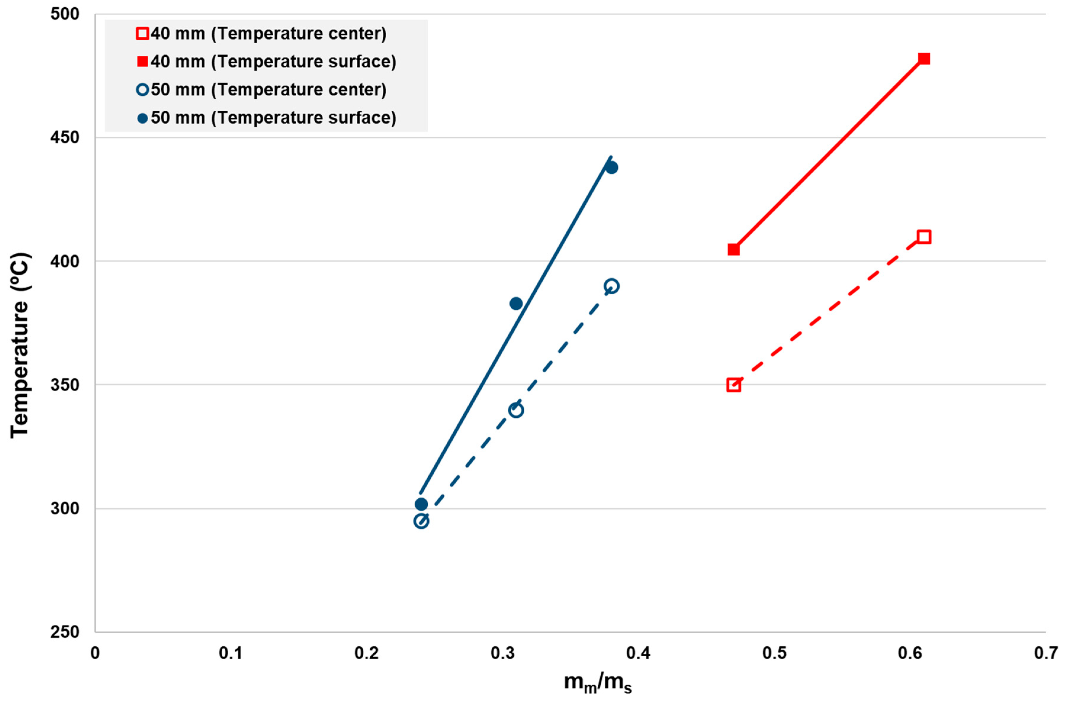
Justification of the temperature reached by the metal spheres at various molten mass (mm)/metal spheres (ms) mass ratio.
-
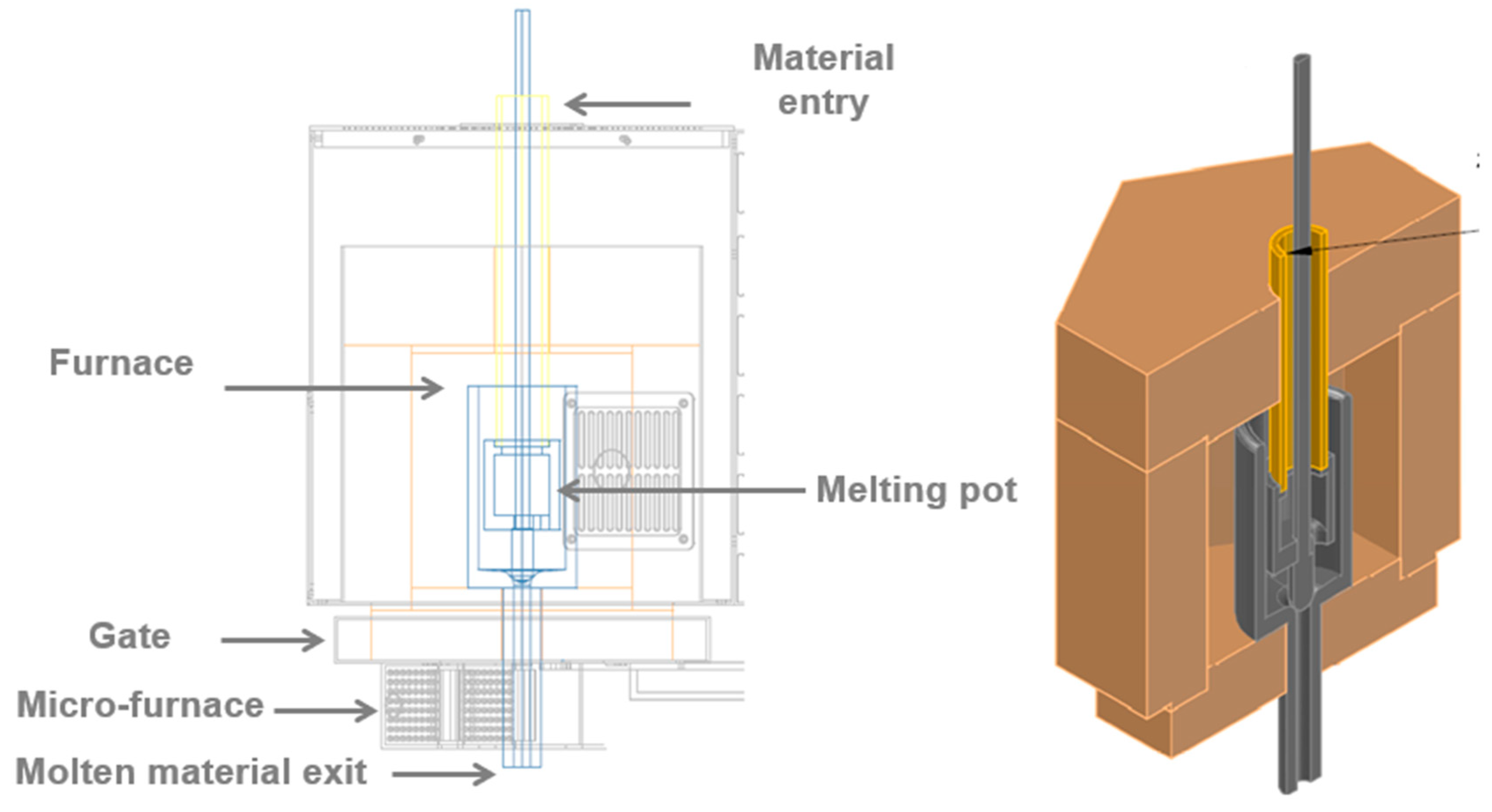
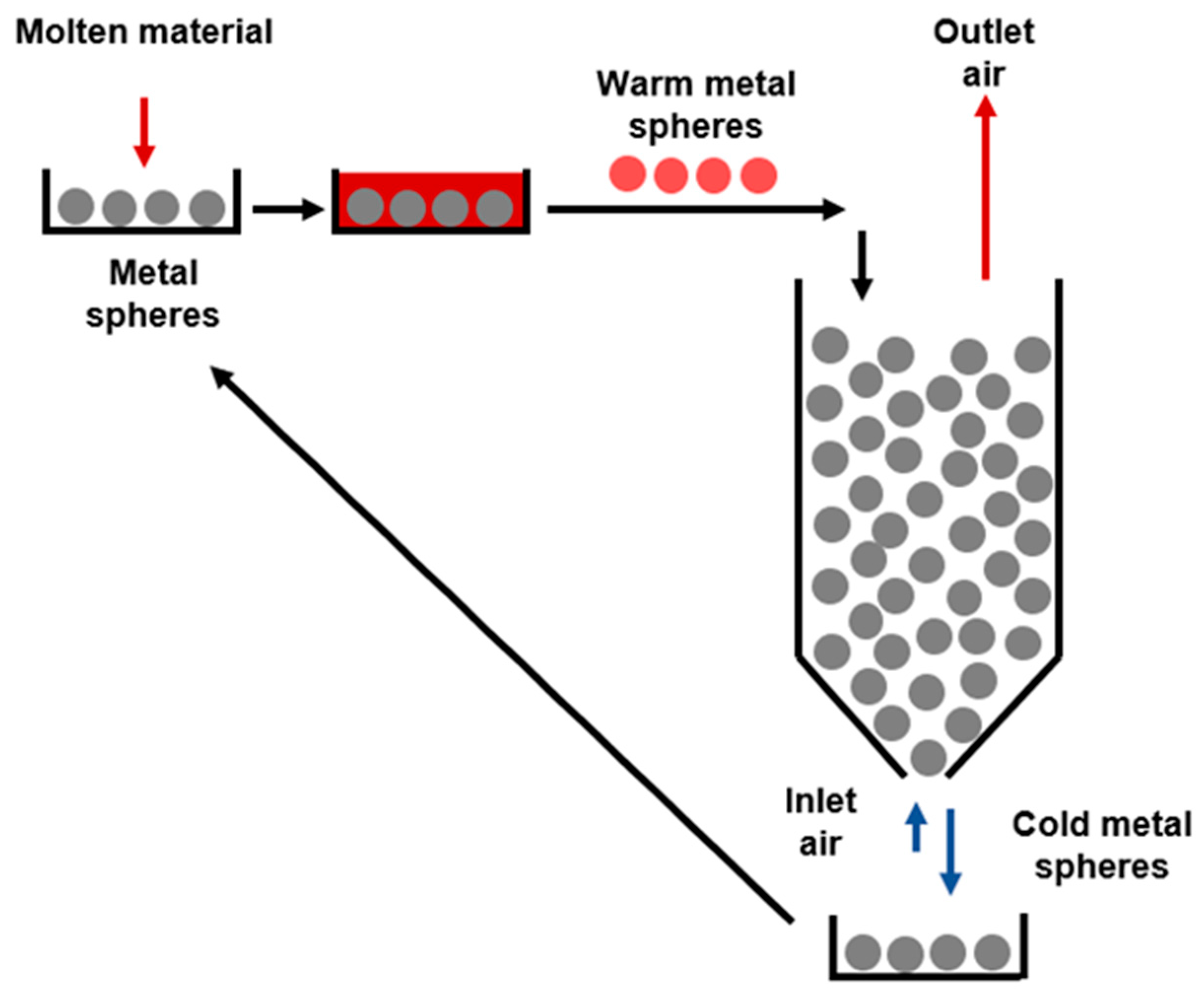
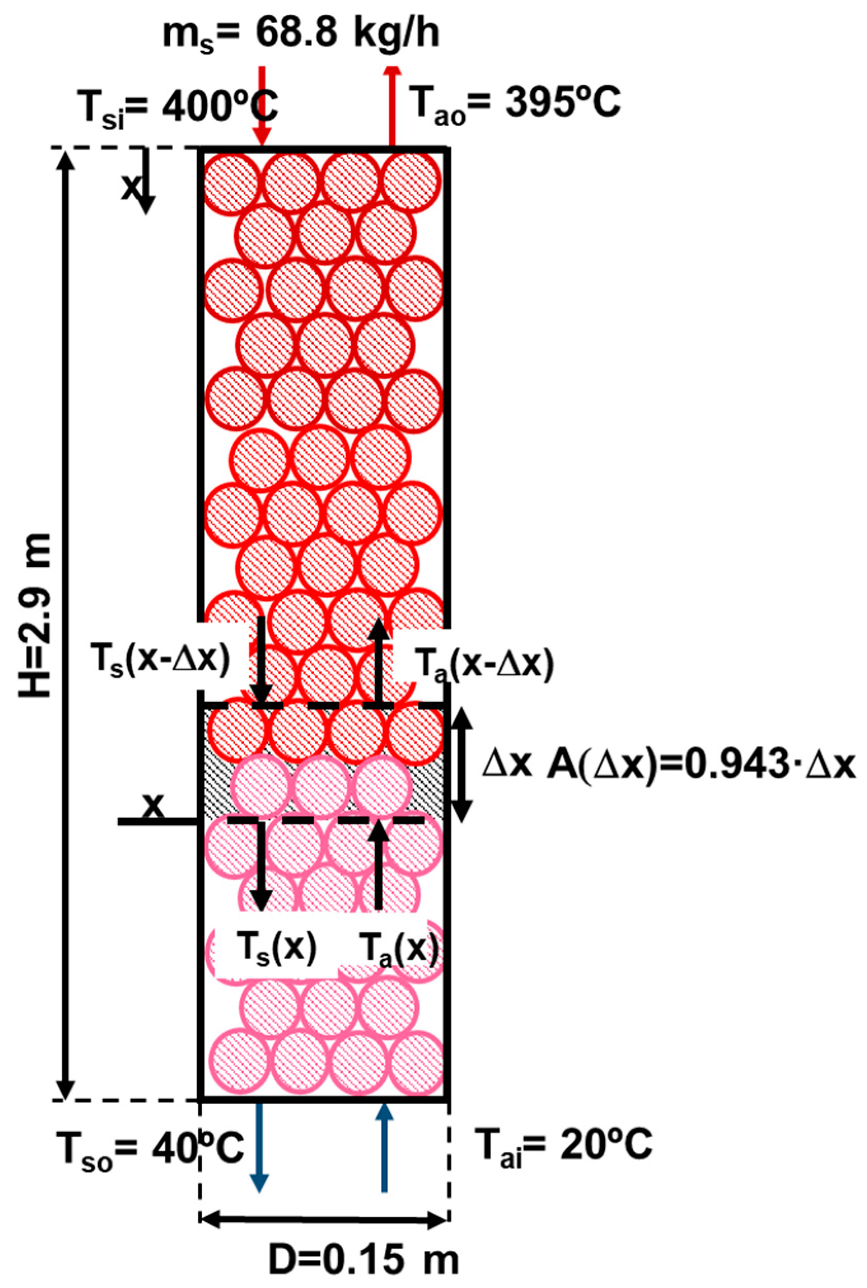
Corroboration of the industrial feasibility of the proposed system in Figure 1 by means of fixed bed (or regenerator) height calculation. For this purpose, the calculation of the convective heat transfer coefficient by solid–air convection is needed. The definition of this step is crucial for checking that the process proposed is of industrial interest.
-
Estimation of the potential energy recovered per kg of molten material.
To meet this end, this work is organized as follows. First, experiments for measuring the maximum temperature that could be reached by the metal spheres were performed. Inasmuch than the study aims to be useful for industrial purposes, the experiments were performed at different mm/ms ratios to reproduce real industrial scenarios. Subsequently, the molten material that was poured over the metal spheres was analyzed by means of X-ray diffraction (XRD) to verify the formation of the characteristic vitreous phase. Afterwards, before estimating the potential energy recovery, the technical feasibility of the proposed cooling process was characterized. To this end, the fixed bed height was calculated following the methodology explained in Section 2.2.4. For its estimation, the previous determination of the convective heat transfer coefficient (h) was necessary. The methodology employed for h estimation can be seen in Appendix A. Two experiments were performed to estimate the metal spheres—air flow temperature profiles in a real fixed bed. The experiments allowed the estimation of h following the assumptions explained in Section 2.2.4. Once the industrial fixed bed height was obtained and analyzed as feasible, the energy recovery per kg of molten material was estimated. To estimate the approximate percentage of the energy recovery in the overall slag manufacturing process, a comparison of the vitreous–mineral phases between our molten material and traditional clinker was done. This comparison allowed ensuring that no significant differences are found and hence that the total energy consumption of our molten material can be approximate to the one of clinker production.

2. Materials and Methods

In order to study the energy recovery efficiency of the cooling and solidification system for the molten synthetic slags, a three-stage laboratory experiment was proposed:
(1)
Melt the waste mixture in an oven in appropriate proportions to achieve a composition similar to blast furnace slags. This stage was addressed in depth in our previous work [11].
(2)
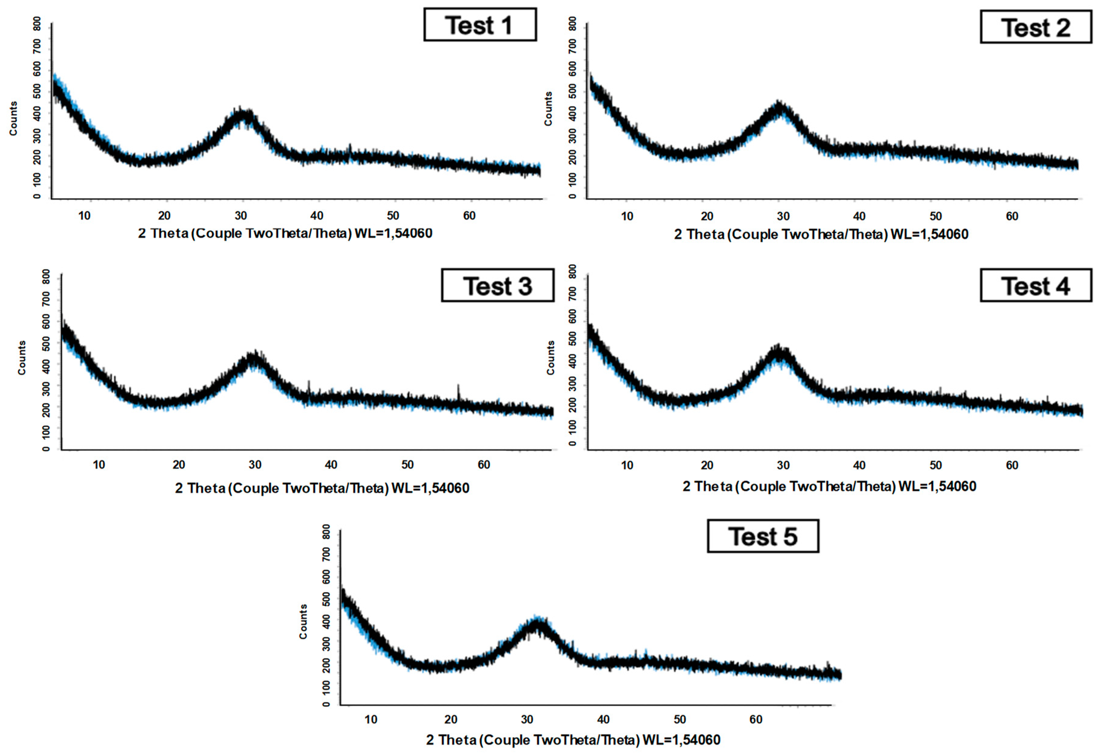
Obtain the temperature reached by the metal spheres when the molten material is poured with different melting/metal mass ratios. Determination of the characteristics of the vitreous phase obtained in order to ensure the vitreous properties of the material solidified.
(3)
Evaluate the energy that can be extracted from a fixed bed of metal spheres at the temperature reached in the previous phase by exchanging energy with an air current.
Below, the materials and methods employed to fulfill this scheme are explained in depth.

2.1. Materials

The mix of waste for manufacturing synthetic slags was defined in a previous work of our group [11]. Three different wastes were selected as raw materials, which were construction and demolition waste, the solid waste stream generated in an aluminum recovery plant, and mussel shell waste from the aquiculture industry. For more information, please see [11].

2.2. Experimental Setup

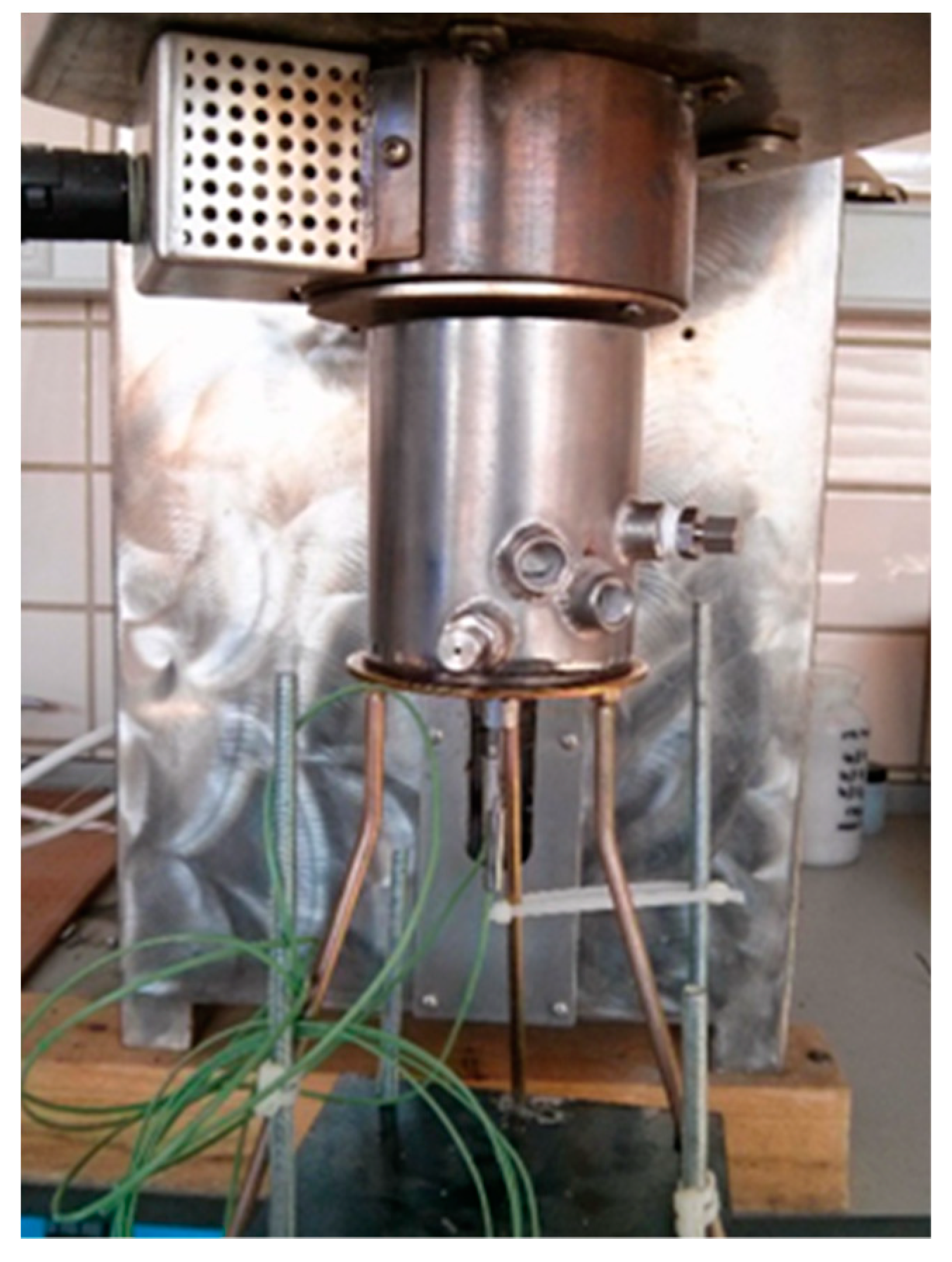
2.2.1. Melting Furnace

The mix of waste was melted by employing the melting furnace (4 kW power) schemed in Figure 2, which was the same one employed in our previous work [11]. In brief, the melting furnace consists of six electrical resistances located inside a hexagonal fusion chamber. The discharge of the molten material is carried out from the bottom of the furnace.

2.2.2. Metal Spheres: Cooling of the Molten Material

The cooling stage to energy recovery from the molten material was based on metal spheres. The first stage was the study of the temperature evolution inside a single metal sphere. To this end, the system shown in Figure 3 was designed. In this system, a single metal sphere welded to a plate was built. The sphere was designed with two perforations in the lower part in which two thermocouples were inserted that allow measuring the temperature data in the center and on the surface of the sphere. All thermocouples were connected to the corresponding data acquisition system. For sake of safety, the sphere was assembled in a metal container and insulated by a refractory material, as can be seen in Figure 3. The system was placed under the melting furnace, and the molten material was poured directly from the furnace onto the sphere. In order to reproduce an industrial environment close to real cases, two sizes of spheres of 40 and 50 mm diameter were used. Figure 3 shows the characteristic dimensions of the 50 mm diameter metal sphere and the ducts in which the thermocouples were inserted. Furthermore, photos of the plates aforementioned with the spheres coupled can be seen. A detailed explanation of properties and composition of the spheres can be found in reference [29].
Figure 4 shows a real photo in which the coupling between the melting furnace outlet and the cooling device with the metal sphere can be observed.

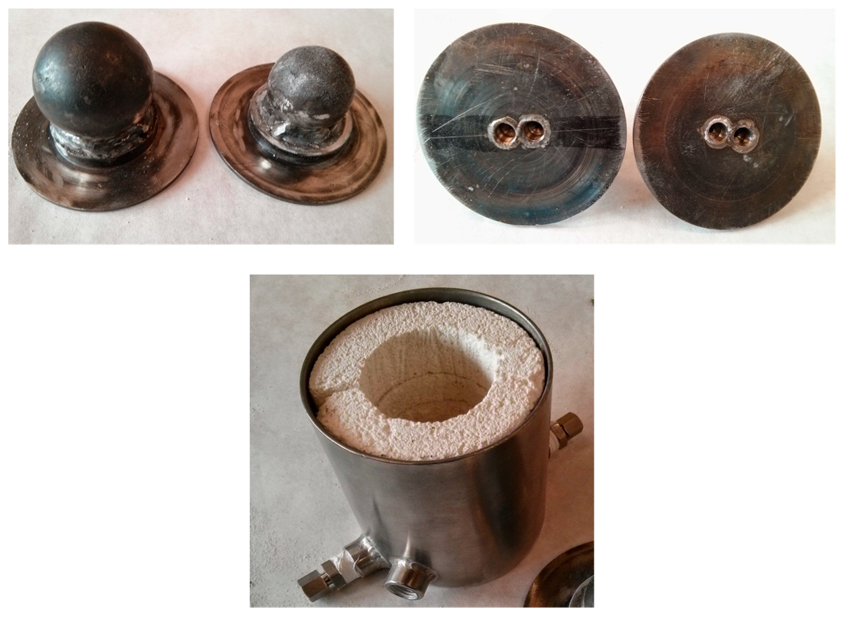
2.2.3. Metal Spheres Packing Device for Energy Recovery

To estimate the potential energy recovery from the metal spheres with air, a fixed bed composed by two baskets filled with metal spheres was designed. The baskets are made of stainless steel and have a mesh that allows the gas to pass through the bed. The needed thermocouples (for temperature measurements) were connected to the data acquisition system. Figure 5 shows an image of the fixed bed and metal sphere baskets.
The metal sphere packing, after being heated in an oven to the desired temperature, was deposited in a thermally insulated vessel that can be seen in Figure 6.
Moreover, the designed device incorporates an air preheater by means of electrical resistance, which allowed performing tests at different initial air temperatures. All the elements described in this section are integrated in the final experimental setup shown in Figure 7.

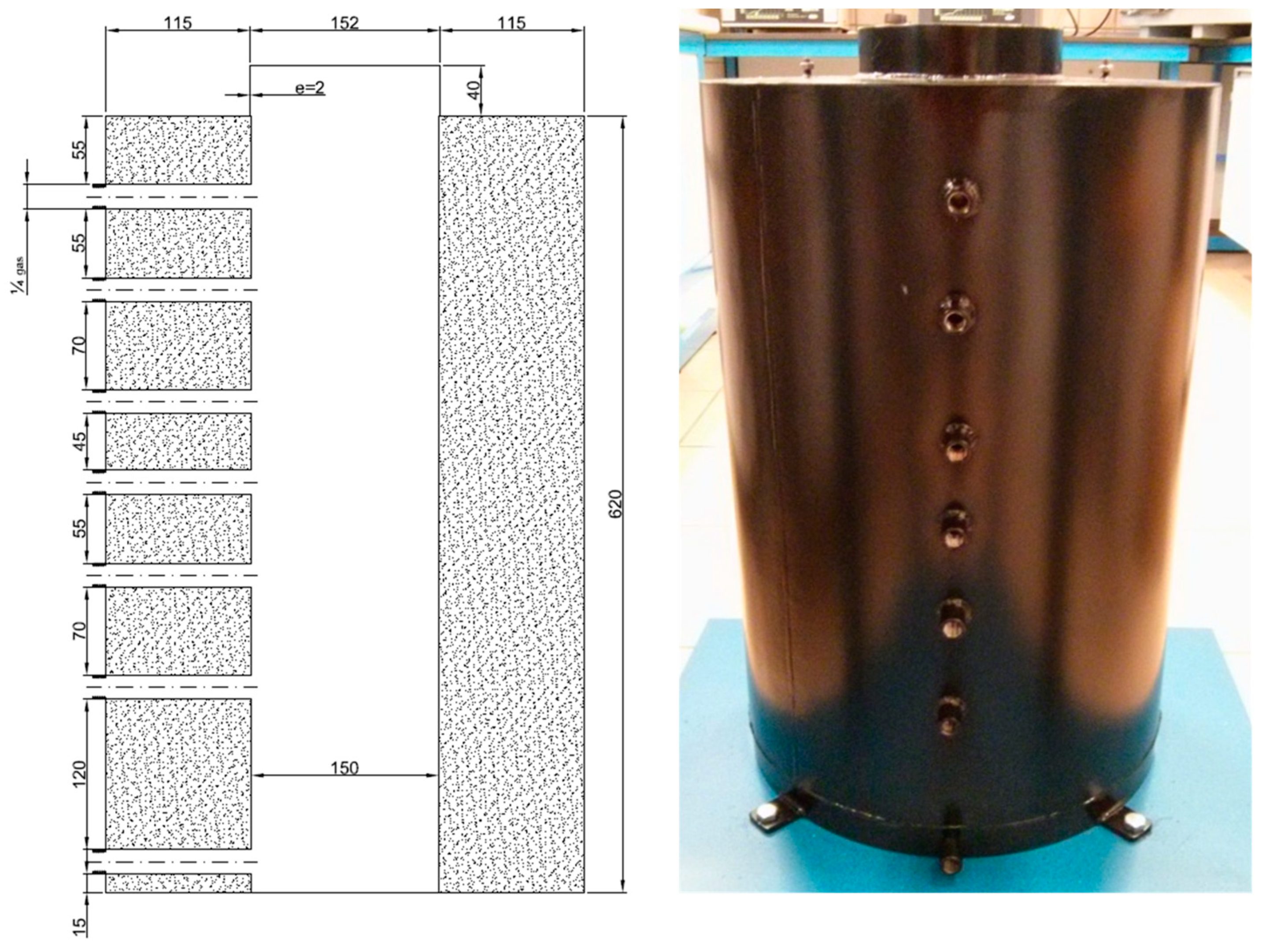
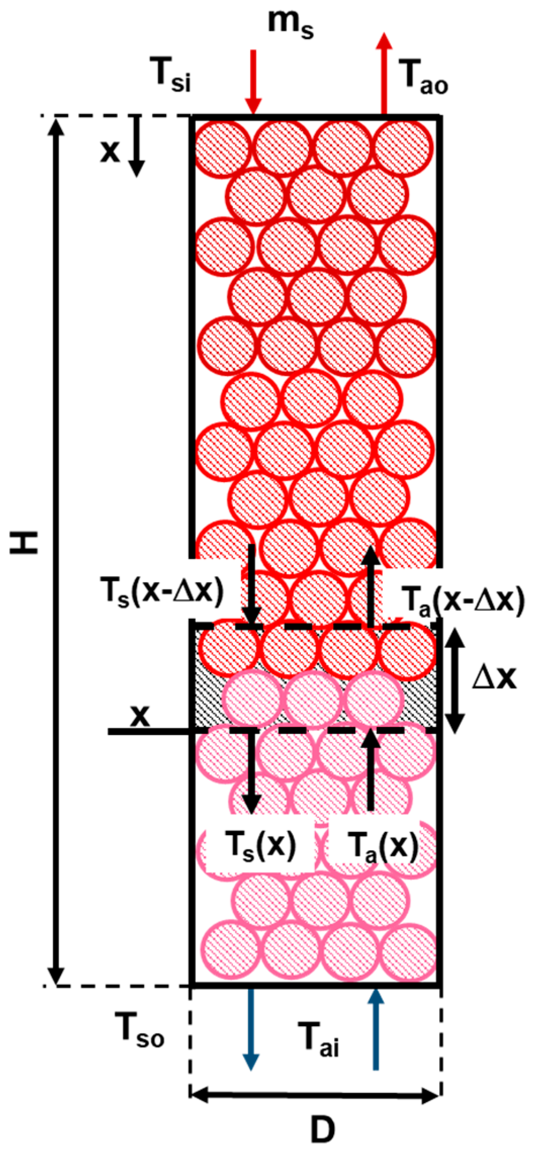
2.2.4. Fixed Bed Height Estimation

The conceptual idea for the fixed bed of metal spheres herein applied consists of the following steps. First, the molten material is poured on the metal spheres. After that, the spheres together with the vitrified material are located in a fixed bed in which the spheres move by gravity slowly (following a plug flux model). Thus, the spheres go from the upper part of the fixed bed to the bottom, cooling with countercurrent air from 400 °C to room temperature. As will be explained in Section 3.1, a temperature of 400 °C can be reached in the spheres, for example with an mm/ms ratio of 0.4 and with a sphere diameter of 50 mm.
The estimation of the potential energy recovery from the proposed process needs the previous calculations of some parameters. Therefore, the purpose of this section was to estimate the residence time of the spheres to produce a temperature decrease from 400 °C to room temperature, as well as the necessary air flow and the temperature that would be reached in the air. The proposed method to obtain these results is a semi-empirical model variation of the temperature of the spheres in the bed. Please see Appendix A for more information. This allowed estimating h′, which is a variation of the original h under the assumptions imposed, which are explained in Appendix A.
Once h′ was known, it was possible to estimate the dimensions of the equipment. To this end, a steady-state balance was performed in the fixed bed regenerator shown in Figure 8. Equations (1) and (2) collect the components of these balance equations. The residence time necessary for achieving a decrease in the metal spheres temperature from 400 to 40 °C was calculated also by means of these balance equations. This calculation allowed obtaining the temperature profile along the fixed bed regenerator (Figure 8).
m s · ( kg h ) · c s ( kJ kg · K ) · ( T s ( x Δ x ) T s ( x ) ) ( K ) = m a ( kg h ) · c a ( kJ kg · K ) · ( T a ( x Δ x ) T a ( x ) ) ( K )
h ( x ) ( kJ h · m 2 · K ) · A ( Δ x ) ( m 2 ) · ( T s ( x Δ x ) + T s ( x ) 2 T a ( x Δ x ) + T a ( x ) 2 ) ( K ) = m a ( kg h ) · c a ( kJ kg · K ) · ( T a ( x Δ x ) T a ( x ) ) ( K )
The equations were solved following a standalone path. Imposing that Ts(x), Ts(x – “∆” x), and Ta (x − “∆” x) are known, it is possible to obtain Ta(x) from Equation (1), as well as “∆” x from Equation (2).

2.3. Physicochemical Characterization

The physicochemical characterization was carried out by means XRD analysis, model AXIOS from Panalytical. The 2θ angle was increased by 0.05°, with a 450 time per step over a range of 10–90°. Then, diffraction patterns were recorded at 40 mA and 45 kV in the cases in which it was necessary, using Cu Kα radiation (λ = 0.154 nm).

2.4. Experimental Plan

To fulfill the scope of the work previously defined, the following experimental plan was designed. The whole experimental tests were divided into two main groups of experiments, corresponding to the same previous division between the justification of the temperature that metal spheres can achieve and the measurement of the air temperature in the fixed bed packing for estimating the potential energy recovery. Table 2 shows the tests performed in both stages. The objective of the first stage was to cover all the possibilities regarding metal spheres diameters and molten quantity. However, the design of the second stage was aimed to acquire data for energy recovery estimation. All the experiments included in Table 2 were conducted twice, ensuring that the results are reproducible with an overall experimental error of ±2%.
After performing the tests included in the second experimental stage, the estimation explained in Section 2.2.4 was carried out to fulfill the aforementioned purpose.

3. Results

The results obtained in the two stages of the experimentation are shown and discussed in this section. Furthermore, chemical and vitreous characterization of the material obtained with this cooling system are given and compared with the ones obtained in our previous work [11].

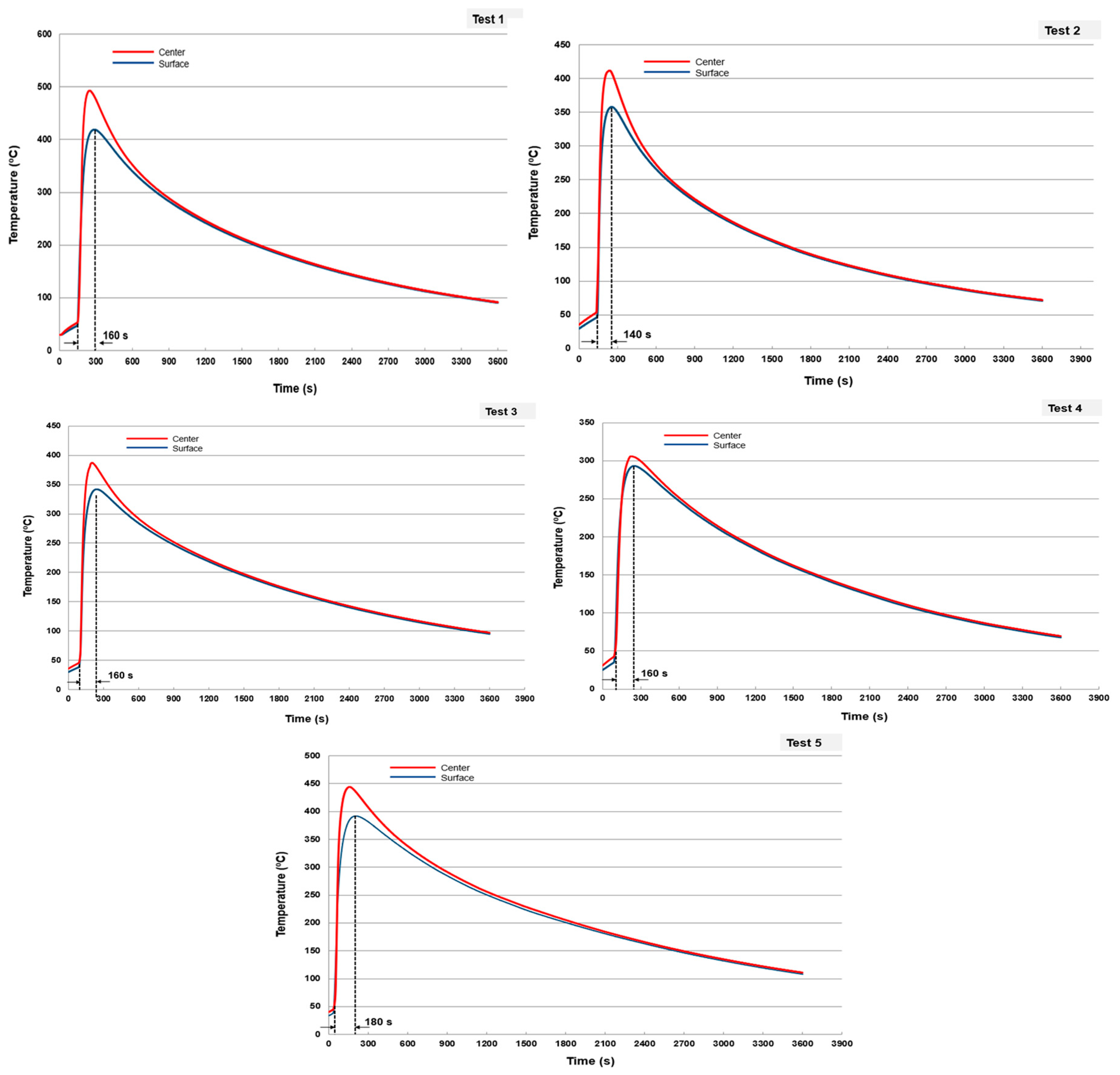
3.1. Energy Transfer from the Molten Material to Metal Spheres

The maximum temperature that the spheres of 40 and 50 mm (industrial application diameters) were determined based on the melt, which was poured over them. To this end, different mm/ms ratio were tested. This ratio was adjusted between 0.24 and 1 based on characteristic values found for slag cooling [30]. In all the experiments, the temperature of the molten material poured over the spheres was 1500 °C. Table 3 shows the characteristic parameters of each of the tests performed as well as the maximum temperatures reached in the center and on the surface of the spheres according to the direct reading of the two thermocouples placed in the spheres (see Figure 3). Additionally, Figure 9 show the evolution of the sphere’s temperature versus time of each test performed.
In Figure 9, it can be seen that the time needed to reach the maximum temperature is 2–3 min. From an industrial point of view, this could be a characteristic time interval between the time of melting fall on the spheres and the time in which the spheres, together with the molten material, are deposited in the spheres packing for energy recovery with air. Figure 10 plotted the maximum temperature reached at the surface and center of the spheres as a function of its diameter and the ratio mm/ms.
From the data presented above, some considerations can be discussed. In the ranges of tested variables, the maximum temperature reached by the spheres is less than 500 °C. Thus, in comparison with the molten material temperatures (1500 °C), the maximum temperature means several energy losses. To obtain a certain temperature (i.e., 400 °C), spheres of smaller diameter need less melt mass (higher ratio mm/ms, but lower mm). Therefore, the energy transfer from the molten material seems more efficient to smaller sphere diameters. This may be caused by the whole covering of the melting material in these cases. Assuming that the material on the metal surface is in thermal equilibrium, it can be deduced that in all the cases tested, the material reaches 400 °C at a cooling rate exceeding 300 °C/min.
Another interesting fact needs some explanation. For the same sphere diameter and equal molten/metal heat transfer coefficient, as the ratio mm/ms increases, the gradient between the maximum surface and center temperature increases. This fact shows that, possibly, the thickness of the melt mass on the surface of the sphere influences the rate of energy transfer from the molten material to the metal sphere. This result needs further optimization, which opens new horizons for future works aimed to increase the energy transfer velocity and minimize the energy losses to the environment.

3.2. Properties of the Cooled Material

To check the existence of a vitreous phase of the cooled material obtained at mm/ms for each ratio tested, an XRD analysis was performed after each test. Figure 11 shows that no differences are found between the properties of the cooled material obtained in each test. The cooled materials exceed 85% of the vitreous phase, confirming that all the mm/ms ratios tested, spheres of 40 and 50 mm produce a material with suitable vitreous properties.
The chemical composition of the waste mix before melting and after melting–cooling is presented in Table 4. Chemical composition was determined using an X-ray fluorescence spectrometer (XRF, Model AXIOS, Panalytical). Thus, it is possible to verify how the material obtained is within the typical ranges of composition of the blast furnace slags (see Table 1). Some losses happen due to the calcination of some components, mainly calcium carbonate, which is converted into calcium oxide and carbon dioxide. This loss in weight causes the variation in the composition after fusion. The sum of the oxides of silicon, calcium, and magnesium is 82.12%, that is, more than two-thirds of the total mass. Moreover, the ratio (CaO + MgO)/SiO2 is 1.16. These two specifications, together with a vitreous phase result, meet the requirements of blast furnace slags to be used as additions to cement, according to EN 15167-1.

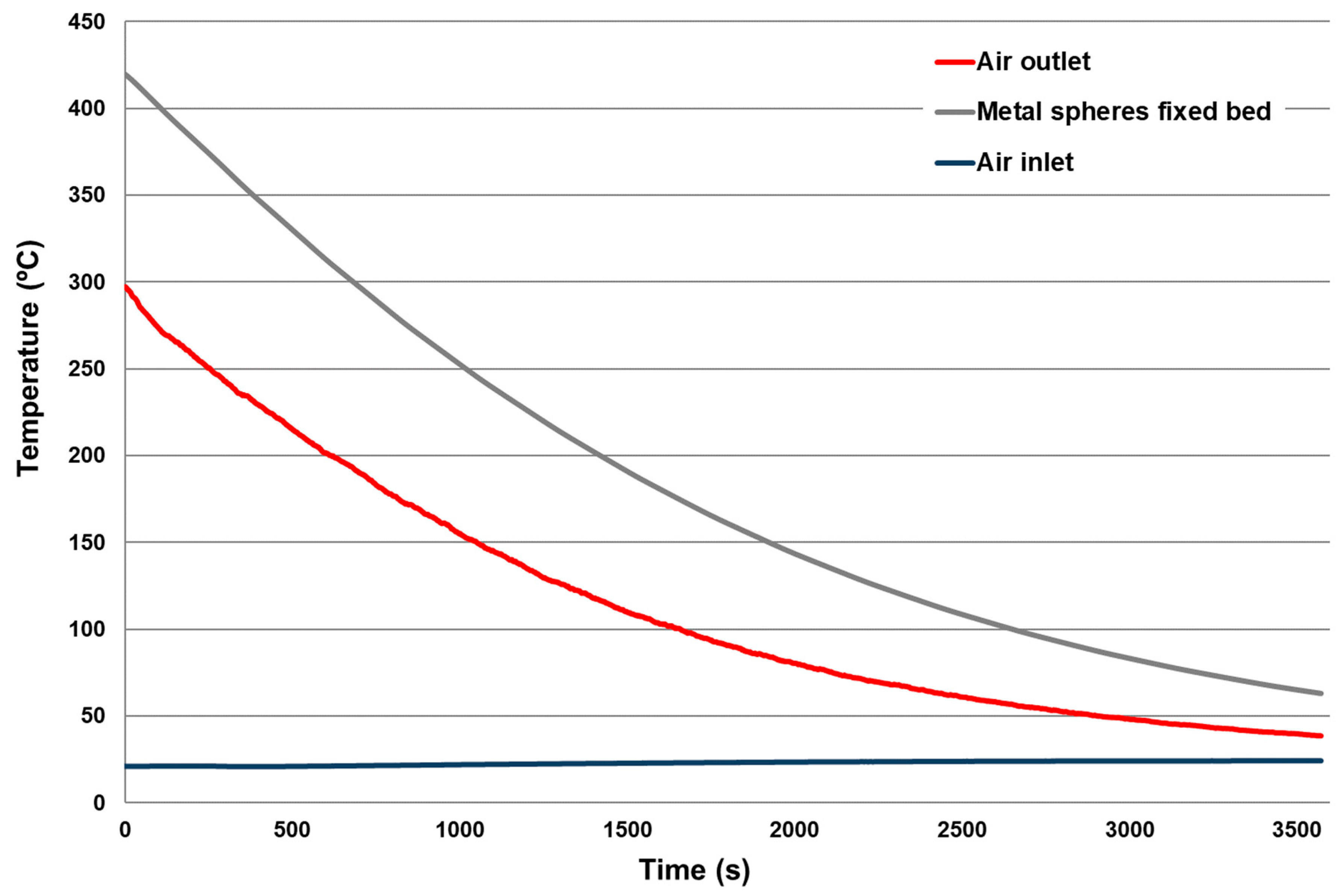
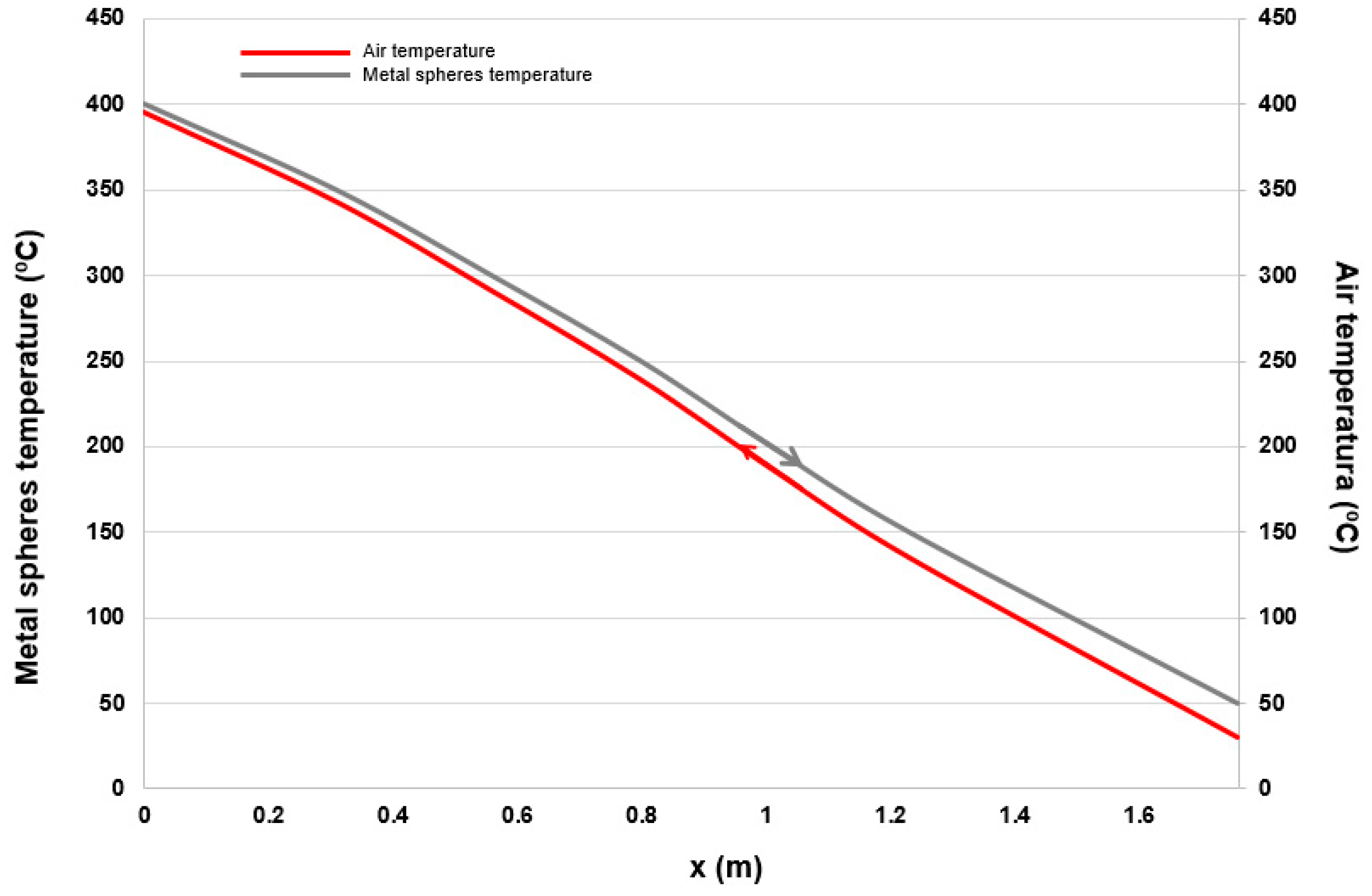
3.3. Estimation of the Energy Recovery Using a Fixed Bed of Metal Spheres with Air

In the case of 50 mm diameter spheres, 23 spheres (≈0.18 m2) were deposited in the bed of dimensions shown in Figure 6. The tests were performed at constant inlet air flow equal to 26 m3/h, which was at room temperature. The inlet air temperature was later varied to 150 °C using the preheater in order to analyze various temperature ranges. The experimental results obtained are shown in Figure 12 and Figure 13, in which the rapid heat dissipation obtained can be verified. Thus, for an inlet air temperature of 20 °C, outlet temperatures greater than 300 °C were achieved, with air residence times in the fixed bed less than one second (Figure 12).
An estimation of h′ was carried out from the data obtained in Figure 12 and Figure 13, splitting the results in equal time interval of 500 s. For spheres temperatures higher than 225 °C, the results obtained in Figure 13 were used; whereas for lower temperatures, the data from Figure 12 were selected. Thus, the following expression was obtained for h′ (Equation (3)), where h′ units are W/m2·K and Ts in °C.
h ( T s ) = 17.545 · e 0.0066 · T s   ( R 2 =   0.9522 )
Once h′ was calculated, it is possible to obtain a real dimension’s estimation of the energy regenerator equipment in steady state. To this end, a steady-state balance was performed, giving as a result the following results under the assumptions indicated in Section 2.2.4: 30.26 kg/h air flow; 68.8 kg/h metal spheres flow. The transfer area metal spheres–air was calculated as A( Δ x) = 0.943 · Δ x. Figure 14 presents the fixed bed regenerator scheme solved.
To obtain the residence time needed for the metal spheres temperature to decrease from 400 to 40 °C and, therefore, to obtain the temperature profiles (both spheres and air) along the fixed bed regenerator, Equations (1) and (2) were employed. The profiles resulted can be seen plotted in Figure 15, needing 2.9 m of fixed bed height and 2.5 h to achieve the transfer imposed.
With the experimental data obtained and to corroborate the hypotheses made, Equation (1) as readjusted, obtaining the following expression:
T s ( x )   =   T a ( x ) + 19.162 · e 0.005 · h ( x ) ( R 2   =   0.9476 ) .
With these results, in the section of the equipment studied, the molten material that could be cooled (imposing mm/ms = 0.4) is 27.52 kg/h, recovering 11,215 kJ/h. Thus means that the maximum energy recovered by air in the equipment per kilogram of molten material would be 408 kJ/kg at 395 °C. The losses that this kind of equipment may have are about 20%. Therefore, it can be deduced that with the dimensions of the equipment obtained, 325 kJ/kg of molten material can be recovered at a temperature higher than 350 °C. In any case, the energy to be recovered would be greater, as long as in this estimation, it has not been considered that the vitrified solid that comes with the metal spheres represent an additional energy recovery potential of about 225 kJ/kg of molten material (employing a Cp value of 0.63 kJ/kg·K [31]). Therefore, it is reasonable that with this equipment, an energy greater than 550 kJ/kg of molten material can be recovered with air at a temperature higher than 350 °C using mm/ms ratios of 0.4. The results obtained in this section are quite conservative, because it is more than likely that a more efficient energy recovery could be obtained by optimizing, among other variables, the mass air flow per unit area.

3.4. Potential Use of the Energy Recovered in the Regenerator in the Manufacture of Synthetic Slags

A possible vitreous material production scheme could correspond to a typical clinker manufacturing process [31], in which, after the rotary kiln, an oven is included where the complete fusion of the material occurs. The process would consist of a preheater, in which part of the calcination reactions would occur; a rotary kiln, in which the decarbonation of the material would be finished and that would take the material to 1300 °C; and finally, a melting or reverberating furnace, where the material that arrives from the rotary kiln would be molten and heat up to 1500 °C to guarantee its fluidity. After melting, the material would be cooled quickly in the fixed bed of metal spheres to achieve the desired vitreous properties.
To confirm the proposed production process, an XRD analysis of the mixed material was performed in the proportions indicated in Section 2.1 and heated to temperatures prior to the melting point (1250–1280 °C). As shown in Figure 16 in which the XRD results are presented, at those temperatures, crystalline phases appear similar to those that occur in the clinkerization process (C2S—Dicalcium Silicate, C3S—Tricalcium Aluminate, C3A—Tricalcium Silicate, CAF—Tetracalcium Aluminoferrite).
Therefore, it can be concluded that synthetic slags have characteristics and mineral phases that are typically found in the raw materials used in the manufacture of the clinker. Furthermore, it can be affirmed that the energy consumption for its manufacture will be of the same order as that consumed in the manufacture of clinker. In this context, the energy recovered in the fixed bed regenerator presented in this work could be used as air at about 350–400 °C. For example, savings in fuel consumption could occur if the regenerator air stream was used as the combustion air inlet stream. Broadly, if 10% higher than the energy consumption of clinker production (about 3800 kJ/kg clinker [32]) is taken as a reference for the energy consumption of synthetic slags, the regenerator’s air flow could result in energy savings in the manufacture of synthetic slags that could be around 15% of the energy needed for its production.

4. Conclusions

In this work, a novel method for energy recovery from the cooling–solidification stage of a synthetic slag manufacturing process was satisfactory studied. The study was evaluated by means of an experimental study that was complemented by theoretical calculations to close the overall performance.
The experimental stage was divided into two differentiated group of tests. The first group aimed to obtain the temperature value of the metal spheres when the molten material was poured over them. The second experimental was carried out to evaluate the metal spheres–air flow temperature profiles in a real fixed bed. During the experimental tests, the scope was to analyze the temperatures obtained in the center and on the surface of the metal spheres. Thanks to this experimental study, it was possible to measure a temperature in the range of 295–410 °C in the center of the sphere and 302–482 °C over the surface. Thus, it allowed setting up a temperature value for the second experimental stage, which consequently allowed the theoretical calculation of the energy recovery per kg of molten slag. Moreover, the molten material that was poured over the metal spheres was analyzed by means of XRD, and the formation of the characteristic vitreous phase was verified.
The main purpose of the theoretical approach was to achieve a fixed bed regenerator height, which proved that the process is viable industrially. To meet this end, h was previously estimated with the help of the values obtained in the second experimental stage. The fixed bed height calculated proved to be industrially achievable. Once the potential industrial fixed bed height was obtained and analyzed as feasible, the energy recovery per kg of molten material was estimated. We estimated that between 325 and 550 kJ/kg of molten material could be recovered, which is 15% of the energy consumption in synthetic slag manufacturing process.
Overall, the results obtained confirmed the potential of our proposal for energy recovery from the cooling–solidification stage of synthetic slag manufacturing. Our work herein studied proved to be of great interest for the industrial scale. The energy recovery for high-energy consumptions industries is one of the key points to achieve a more sustainable industrial model.

Author Contributions

Conceptualization, L.F.V., B.N. and M.R.-G.; methodology, M.R.-G., F.M.B.-M.; software, M.R.-G., F.M.B.-M.; validation, M.R.-G., F.M.B.-M.; formal analysis, F.M.B.-M.; investigation, L.F.V., B.N., M.R.-G., F.M.B.-M.; resources, L.F.V., B.N.; data curation, M.R.-G.; writing—original draft preparation, L.F.V., F.M.B.-M.; writing—review and editing, L.F.V., M.R.-G., F.M.B.-M.; visualization, M.R.-G., F.M.B.-M., X.X.; supervision, L.F.V., F.M.B.-M.; project administration, L.F.V., B.N.; funding acquisition, L.F.V., B.N. All authors have read and agreed to the published version of the manuscript.

Funding

This work was supported by University of Seville through V PPIT-US. Financial support for this work was also provided by MAVIT project (FEDER-INNTERCONECTA).

Conflicts of Interest

The authors declare no conflict of interest.

Abbreviations

mmmolten mass
msspheres mass
Tsispheres temperature inlet
Tsospheres temperature outlet
Taiair temperature inlet
Taoair temperature outlet
Tsspheres temperature
Taair temperature
Hfixed bed regenerator height
Dfixed bed regenerator diameter
hconvective heat transfer coefficient
h′convective heat transfer coefficient variation
Csspheres calorific value
Caair calorific value
A(“∆” x)transfer area metal spheres–air

Appendix A

Existing models for thermal regenerators require a very rigorous adjustment of various parameters such as speed, Reynolds number, Prandtl number, or the characteristic diameter of the spheres. In addition, when considering the balance equations that allow determining the behavior of the equipment, it is necessary to solve a nonlinear equation system that requires approximate numerical techniques for its resolution. However, semi-empirical bed models are usually resolved under the consideration that the sphere internal resistance is negligible to heat conduction [33]. This hypothesis allows easily estimating the cooling temperature along the fixed bed with an exponentially function as follows (Equation (A1)):
T ( t )   =   T + ( T i T ) · e h ρ s · c s · D p · t
where T(t) is the sphere temperature at time t (°C); T is the ambient temperature that surrounds the sphere (°C); Ti is the sphere temperature in t = 0 (°C); ρs is the sphere density (kg/m3); cs is the specific heat of the sphere (J/kg·K); h is the convective heat transfer coefficient by solid–air convection (W/m2·K); and Dp is the sphere diameter (m).
At a constant descent rate of the spheres along the fixed bed and in a steady state, Equation (1) can be expressed as follows (Equation (A2)):
T ( x ) = A ( x ) + B ( x ) · e C ( x ) .
Thus, for a coordinate x in the bed, T(x) is the temperature of the spheres; A(x) is the temperature of the air surrounding the spheres inside the bed; B(x) is a constant function of A(x); and C(x) has the expression the following expression (Equation (A3)):
C ( x ) = h ( x ) ρ s · c s · D p
where h′(x) is the convective heat transfer coefficient at coordinate x. Since ρs, cs, and Dp are constant, it can be affirmed that C(x) only depends on h′(x). This allows finding expressions that explain the variation of h′(x) knowing the temperatures of the sphere and the surrounding air. Furthermore, h′(x) depends on both air properties–flow conditions and the geometry of the metal spheres of the bed.
Strictly, the h coefficient should be calculated under a complete experimental design in a steady state of the temperatures of the spheres and varying the following parameters: Reynolds number (Re), Prandtl number (Pr), and sphere diameter to bed diameter ratio. Nevertheless, due to the estimative purposes of this work, the calculation of h′(x) was done with a fixed bed of metal spheres similar to the one shown in Figure A1. In this system, the following parameters were measured: the temperature of the spheres (Ts) and the air temperatures at the inlet and outlet of the bed (Tai and Tao, respectively), as well as the mass air flow.
Figure A1. Scheme of the experimental system used to estimate h′(x).
Processes 08 01590 g0a1
With this system, the energy transfer balance for a time of experimentation t approximates the expression indicated by Equation (A4):
h · A · ( T ¯ S T ¯ a ) = m a · c g · ( T ¯ ai T ¯ ao )
where h′ is the convective heat transfer coefficient (W/m2·K); A is the transfer area (m2); T ¯ s is the average spheres temperature in the experimentation time t (°C); T ¯ a is the average temperature between the inlet air and outlet air in the experimentation time t (°C); T ¯ ao is the average outlet air temperature in the experimentation time t (°C); T ¯ ai is the average inlet air temperature in the experimentation time t (°C); m a is the inlet air mass flow (kg/s); and Cg is the air-specific heat (J/kg·K).

References

  1. Royo, P.; Acevedo, L.; Ferreira, V.J.; García-Armingol, T.; López-Sabirón, A.M.; Ferreira, G. High-temperature PCM-based thermal energy storage for industrial furnaces installed in energy-intensive industries. Energy 2019, 173, 1030–1040. [Google Scholar] [CrossRef]
  2. Baena-Moreno, F.M.; Rodríguez-Galán, M.; Vega, F.; Reina, T.R.; Vilches, L.F.; Navarrete, B. Regeneration of sodium hydroxide from a biogas upgrading unit through the synthesis of precipitated calcium carbonate: An experimental influence study of reaction parameters. Processes 2018, 6, 205. [Google Scholar] [CrossRef] [Green Version]
  3. Peceño, B.; Leiva, C.; Alonso-Fariñas, B.; Gallego-Schmid, A. Is recycling always the best option? Environmental assessment of recycling of seashell as aggregates in noise barriers. Processes 2020, 8, 776. [Google Scholar] [CrossRef]
  4. González-Arias, J.; Sánchez, M.E.; Martínez, E.J.; Covalski, C.; Alonso-Simón, A.; González, R.; Cara-Jiménez, J. Hydrothermal carbonization of olive tree pruning as a sustainableway for improving biomass energy potential: Effect of reaction parameters on fuel properties. Processes 2020, 8, 1201. [Google Scholar] [CrossRef]
  5. Philip, P.T.; Hannaford, A.L.; Konick, E. Methods of Making Cementitious Compositions from Waste Products. U.S. Patent 4756761A, 16 June 1986. [Google Scholar]
  6. Iglesias, J.; Tuya, A.; Peña, F. Procedure for Obtaining Calcium Aluminate From Waste Obtained Following Treatment of Saline Dross From the Production of Secondary Aluminium. U.S. Patent 20110293494A1, 18 July 2011. [Google Scholar]
  7. Akiyama, K. Process for the Manufacture of Aluminous Cement From Aluminum Smelting Residue. U.S. Patent 4071373, 6 July 1976. [Google Scholar]
  8. Leiva, C.; Arenas, C.; Alonso-Fariñas, B.; Vilches, L.F.; Peceño, B.; Rodriguez-Galán, M.; Baena, F. Characteristics of fired bricks with co-combustion fly ashes. J. Build. Eng. 2016, 5. [Google Scholar] [CrossRef]
  9. Karellas, S.; Leontaritis, A.D.; Panousis, G.; Bellos, E.; Kakaras, E. Energetic and exergetic analysis of waste heat recovery systems in the cement industry. Energy 2013, 58, 147–156. [Google Scholar] [CrossRef]
  10. Hara, T.; Shima, H.; Yoshida, Y.; Matsuhashi, R. Model analysis of an inter-industrial and inter-regional waste recycling system in Japan. Energy 2007, 32, 609–618. [Google Scholar] [CrossRef]
  11. Rodríguez-Galán, M.; Alonso-Fariñas, B.; Baena-Moreno, F.M.; Leiva, C.; Navarrete, B.; Vilches, L.F. Synthetic slag production method based on a solid waste mix vitrification for the manufacturing of slag-cement. Materials 2019, 12, 208. [Google Scholar] [CrossRef] [Green Version]
  12. Motz, H.; Geiseler, J. Products of steel slags an opportunity to save natural resources. Waste Manag. 2001. [Google Scholar] [CrossRef]
  13. Zhu, J.; Zhong, Q.; Chen, G.; Li, D. Effect of particlesize of blast furnace slag on properties of Portland cement. Procedia Eng. 2012, 27, 231–236. [Google Scholar] [CrossRef] [Green Version]
  14. Puertas, F. Escorias de alto horno: Composición y comportamiento hidráulico. Mater. Construcción 1993, 43, 37–48. [Google Scholar] [CrossRef] [Green Version]
  15. BSI. Granulated Slag Ground from High Blast Furnace for Use in Concrete, Mortar and Paste; British Standards Institution: London, UK, 2006. [Google Scholar]
  16. Wang, K.S.; Lin, K.L.; Tzeng, B.Y. Latent hydraulic reactivity of blended cement incorporating slag made from municipal solid waste incinerator fly ash. J. Air Waste Manag. Assoc. 2003. [Google Scholar] [CrossRef] [PubMed] [Green Version]
  17. Reino García, H. Supercem®. Experiencia de Holcim (España) con cementos con escorias de alto horno altamente adicionados. Patol. Cim. Estruct. Hormig. 2013. [Google Scholar]
  18. Li, J.; Mou, Q.; Zeng, Q.; Yu, Y. Experimental study on precipitation behavior of spinels in stainless steel-making slag under heating treatment. Processes 2019, 7, 487. [Google Scholar] [CrossRef] [Green Version]
  19. Zhang, H.; Wang, H.; Zhu, X.; Qiu, Y.J.; Li, K.; Chen, R.; Liao, Q. A review of waste heat recovery technologies towards molten slag in steel industry. Appl. Energy 2013, 112, 956–966. [Google Scholar] [CrossRef]
  20. Xiong, B.; Chen, L.; Meng, F.; Sun, F. Modeling and performance analysis of a two-stage thermoelectric energy harvesting system from blast furnace slag water waste heat. Energy 2014, 77, 562–569. [Google Scholar] [CrossRef]
  21. Wang, Q.; Wang, Q.; Tian, Q.; Guo, X. Simulation study and industrial application of enhanced arsenic removal by regulating the proportion of concentrates in the SKS copper smelting process. Processes 2020, 8, 385. [Google Scholar] [CrossRef] [Green Version]
  22. Ishaq, H.; Dincer, I.; Naterer, G.F. Exergy and cost analyses of waste heat recovery from furnace cement slag for clean hydrogen production. Energy 2019, 172, 1243–1253. [Google Scholar] [CrossRef]
  23. Barati, M.; Esfahani, S.; Utigard, T.A. Energy recovery from high temperature slags. Energy 2011, 36, 5440–5449. [Google Scholar] [CrossRef]
  24. Company, N. Metodo Para Enfriar Material Abrasivo Aluminoso Fundido. ES Patent ES399446, 3 February 1972. [Google Scholar]
  25. Hulek, A.; Ritzberguer, F. Method of Continuously Producing Vitreous Blast Furnace Slag. U.S. Patent 6250109B1, 10 July 1998. [Google Scholar]
  26. Jirou, K.; Yasuto, T.; Ohkoshi, K. Apparatus for Manufacturing Vitreous Slag. U.S. Patent 4330264A, 18 May 1982. [Google Scholar]
  27. Nakatani, G.; Kanai, K.; Itoh, H.; Takasaki, Y.; Ohkoshi, K.; Yanagida, Y. Apparatus for Manufacturing Rapidly Cooled Solidified Slag. U.S. Patent 4420304A, 13 December 1983. [Google Scholar]
  28. Unit, A.G. Low Energy Slag and Cement Production. U.S. Patent 9233485B1, 12 January 2016. [Google Scholar]
  29. Gresesqui-Lobaina, E.; Rodríguez-González, I.; Fernández-Columbié, T. Characterization of steel 70XL used in the manufacture of balls for the clinker’s milling. Min. Geol. 2017. Available online: https://www.redalyc.org/jatsRepo/2235/223553249009/html/index.html (accessed on 24 November 2020).
  30. Shakurov, A.G.; Shkol’nik, Y.S.; Parshin, V.M.; Chertov, A.D.; Zhuravlev, V.V. Cooling and solidification of slag melt in spherical packing. Steel Transl. 2012. [Google Scholar] [CrossRef]
  31. Mills, K.C. The estimation of slag properties. In Proceedings of the Southern African Pyrometallurgy International Conference, Johannesburg, South Africa, 6–9 March 2011. [Google Scholar]
  32. Castillo Neyra, P. Manual Práctico de Combustión y Clinkerización. 1990. Available online: https://dl-manual.com/download/manual-practico-de-combustion-y-clinkerizacion-6vj3xerk20oe?hash=168fd0ddbedc13b8ad71e8ec972e7a70 (accessed on 30 November 2020).
  33. Incropera, F.P.; deWitt, D.P. Fundamentos de Transferencia de Calor; Pearson Prentice Hall: Upper Saddle River, NJ, USA, 1999; ISBN 970-17-0170-4. [Google Scholar]
Figure 1. Conceptual scheme of the energy recovery process proposed in this work.
Processes 08 01590 g001
Figure 2. Melting furnace scheme.
Processes 08 01590 g002
Figure 3. Scheme of the device for cooling molten material with metal spheres and views of the containment vessel.
Processes 08 01590 g003aProcesses 08 01590 g003b
Figure 4. Coupling of the melting furnace outlet and the cooling device.
Processes 08 01590 g004
Figure 5. Metal spheres packing device.
Processes 08 01590 g005
Figure 6. Thermally insulated vessel (dimensions in mm).
Processes 08 01590 g006
Figure 7. Complete metal spheres packing device for energy recovery.
Processes 08 01590 g007
Figure 8. Fixed bed regenerator scheme.
Processes 08 01590 g008
Figure 9. Temperature evolution.
Processes 08 01590 g009
Figure 10. Maximum temperature reached at the surface and center of the spheres as a function of its diameter and the ratio mm/ms.
Processes 08 01590 g010
Figure 11. Diffractograms of tests 1 to 5.
Processes 08 01590 g011
Figure 12. Evolution of temperatures in the system for entering air at room temperature.
Processes 08 01590 g012
Figure 13. Evolution of temperatures in the system for inlet air at 150 °C.
Processes 08 01590 g013
Figure 14. Fixed bed regenerator scheme solved.
Processes 08 01590 g014
Figure 15. Temperature profiles of metal spheres and air in the fixed bed.
Processes 08 01590 g015
Figure 16. Diffractogram with crystalline phases of the waste mixture (1250–1280 °C).
Processes 08 01590 g016
Table 1. Typical composition ranges of blast furnace slags. Own elaboration based on [12,13,14].
Composition RangeSiO2CaOAl2O3MgOFe2O3SO3Na2OK2O
27–4030–505–151–150.2–2.51–2.50.1–30.1–3
Table 2. Experimental plan.
First Experimental Stage
TestSphere mass (g)Melt mass (g)mm/ms
1260157.50.61
2260122.50.47
3510157.50.31
4510122.50.24
5510192.50.38
Second Experimental Stage
TestMetal spheres diameter (mm)Air inlet temperature (°C)Experimental time (s)
65020–253000
7501502500
Table 3. Main characteristics of the different tests performed and temperatures reached in the metal spheres.
TestSphere Mass (g)Melt Mass (g)mm/msTemperature in the Center of the Sphere (°C)Temperature in the Surface of the Sphere (°C)
1260157.50.61410482
2260122.50.47350405
3510157.50.31340383
4510122.50.24295302
5510192.50.38390438
Table 4. Chemical composition of waste before–after melting and solidification (%) (C.L: calcination losses).
SiO2Al2O3Fe2O3MnOMgOCaONa2OK2OTiO2P2O5SO3C.L.
Before melting25.28.41.390.041.1230.931.030.660.20.070.2827.81
After melting38.0511.421.770.071.4442.631.360.790.320.10.680.21
Deviations±0.68±1.13±0.34±0.00±0.06±0.49±0.07±0.04±0.01±0.01±0.21±0.31
Publisher’s Note: MDPI stays neutral with regard to jurisdictional claims in published maps and institutional affiliations.

