Processing Methods Used in the Fabrication of Macrostructures Containing 1D Carbon Nanomaterials for Catalysis


Abstract
1. Introduction
2. Application of Carbon Nanofibers Immobilized on Macro-Structures in Catalysis
2.1. Carbon Nanofibers in Catalysis
2.2. Macro-Structures in Catalysis
3. In Situ Preparation of CNF Structures
3.1. Electrospinning
3.2. Chemical Vapor Deposition
- -
- choice of carbon source: linear hydrocarbons (methane, ethylene, acetylene) form straight CNF, while cyclic hydrocarbons (benzene, toluene, xylene) form relatively curved CNF;
- -
- catalyst particle size controls the fiber diameter;
- -
- catalyst selection influences shape and size depending on their carbon diffusion rates (Fe, Ni, and Co have excellent such rates);
- -
- substrate–catalyst interactions are determinant to maintain a stable and uniform catalyst particle size and thus uniform formation of CNF.
4. Ex Situ Preparation of CNF Structures
4.1. Preparation of Stable CNF Dispersions
4.2. Improving the Robustness of Free-Standing CNF Structures
4.3. Preparation of Macro-Structures with Pre-Formed CNF
4.3.1. Vacuum Filtration
4.3.2. Deposition Coating
4.3.3. Spray-Coating
4.3.4. Spin-Coating
4.3.5. Printing
5. Catalytic Applications
6. Future Outlooks and Concluding Remarks
- -
- improved robustness of electrospinning-prepared CNF structures;
- -
- development of alloyed metallic catalysts for low-cost synthesis of CNF films by CVD;
- -
- large-scale and high-throughput fabrication methods for structures prepared by spin- and spray-coating;
- -
- new CNF formulations for printing to find compromises between CNF surface availability for catalytic reactions and mechanical robustness, in particular for novel 3D printing applications.
7. Conclusions
Author Contributions
Funding
Acknowledgments
Conflicts of Interest
References
- Louis, B.; Bégin, D.; Ledoux, M.J.; Pham-Huu, C. Advances in the Use of Carbon Nanomaterials in Catalysis. In Ordered Porous Solids; Elsevier: Amsterdam, The Netherlands, 2009; pp. 621–649. [Google Scholar]
- Hiremath, N.; Bhat, G. High-performance carbon nanofibers and nanotubes. In Structure and Properties of High-Performance Fibers; Elsevier Inc.: Amsterdam, The Netherlands, 2017; pp. 79–109. [Google Scholar]
- Martin-Gullon, I.; Vera, J.; Conesa, J.A.; González, J.L.; Merino, C. Differences between carbon nanofibers produced using Fe and Ni catalysts in a floating catalyst reactor. Carbon 2006, 44, 1572–1580. [Google Scholar] [CrossRef]
- Van Dommelle, S. Nitrogen Doped Carbon Nanotubes: Synthesis, Characterization and Catalysis. Ph.D. Thesis, Utrecht University, Utrecht, The Netherlands, 2008. [Google Scholar]
- Shu, G.J.; Liou, S.C.; Karna, S.; Sankar, R.; Hayashi, M.; Chu, M.W.; Chou, F.C. Graphene-like conjugated π bond system in Pb1-xSnxSe. Appl. Phys. Lett. 2015, 106, 122101. [Google Scholar] [CrossRef]
- Serp, P.; Machado, B. Nanostructured Carbon Materials for Catalysis; The Royal Society of Chemistry: London, UK, 2015. [Google Scholar]
- Figueiredo, J.L.; Pereira, M.F.R.; Freitas, M.M.A.; Órfão, J.J.M. Modification of the surface chemistry of activated carbons. Carbon 1999, 37, 1379–1389. [Google Scholar] [CrossRef]
- Cabiac, A.; Cacciaguerra, T.; Trens, P.; Durand, R.; Delahay, G.; Medevielle, A.; Plée, D.; Coq, B. Influence of textural properties of activated carbons on Pd/carbon catalysts synthesis for cinnamaldehyde hydrogenation. Appl. Catal. A Gen. 2008, 340, 229–235. [Google Scholar] [CrossRef]
- Amadou, J.; Chizari, K.; Houllé, M.; Janowska, I.; Ersen, O.; Bégin, D.; Pham-Huu, C. N-doped carbon nanotubes for liquid-phase CC bond hydrogenation. Catal. Today 2008, 138, 62–68. [Google Scholar] [CrossRef]
- Solhy, A.; Machado, B.F.; Beausoleil, J.; Kihn, Y.; Gonçalves, F.; Pereira, M.F.R.; Órfão, J.J.M.; Figueiredo, J.L.; Faria, J.L.; Serp, P. MWCNT activation and its influence on the catalytic performance of Pt/MWCNT catalysts for selective hydrogenation. Carbon 2008, 46, 1194–1207. [Google Scholar] [CrossRef]
- Farzadkia, M.; Shahamat, Y.D.; Nasseri, S.; Mahvi, A.H.; Gholami, M.; Shahryari, A. Catalytic Ozonation of Phenolic Wastewater: Identification and Toxicity of Intermediates. J. Eng. 2014, 2014, 520929. [Google Scholar] [CrossRef]
- Yang, S.; Li, X.; Zhu, W.; Wang, J.; Descorme, C. Catalytic activity, stability and structure of multi-walled carbon nanotubes in the wet air oxidation of phenol. Carbon 2008, 46, 445–452. [Google Scholar] [CrossRef]
- Wepasnick, K.A.; Smith, B.A.; Schrote, K.E.; Wilson, H.K.; Diegelmann, S.R.; Fairbrother, D.H. Surface and structural characterization of multi-walled carbon nanotubes following different oxidative treatments. Carbon 2011, 49, 24–36. [Google Scholar] [CrossRef]
- Vanyorek, L.; Meszaros, R.; Barany, S. Surface and electrosurface characterization of surface-oxidized multi-walled N-doped carbon nanotubes. Colloids Surf. A Physicochem. Eng. Asp. 2014, 448, 140–146. [Google Scholar] [CrossRef]
- Serp, P.; Figueiredo, J.L. (Eds.) Carbon Materials for Catalysis; John Wiley & Sons, Inc.: Hoboken, NJ, USA, 2008. [Google Scholar]
- IUPAC Compendium of Chemical Terminology; Wiley-Blackwell: Hoboken, NJ, USA, 2009.
- Thakur, D.B.; Tiggelaar, R.M.; Gardeniers, J.G.E.; Lefferts, L.; Seshan, K. Silicon based microreactors for catalytic reduction in aqueous phase: Use of carbon nanofiber supported palladium catalyst. Chem. Eng. J. 2013, 227, 128–136. [Google Scholar] [CrossRef]
- Donaldson, K.; Poland, C.A.; Murphy, F.A.; MacFarlane, M.; Chernova, T.; Schinwald, A. Pulmonary toxicity of carbon nanotubes and asbestos—Similarities and differences. Adv. Drug Deliv. Rev. 2013, 65, 2078–2086. [Google Scholar] [CrossRef] [PubMed]
- Toyokuni, S. Genotoxicity and carcinogenicity risk of carbon nanotubes. Adv. Drug Deliv. Rev. 2013, 65, 2098–2110. [Google Scholar] [CrossRef]
- Shvedova, A.A.; Yanamala, N.; Kisin, E.R.; Tkach, A.V.; Murray, A.R.; Hubbs, A.; Chirila, M.M.; Keohavong, P.; Sycheva, L.P.; Kagan, V.E.; et al. Long-term effects of carbon containing engineered nanomaterials and asbestos in the lung: One year postexposure comparisons. Am. J. Physiol. Lung Cell. Mol. Physiol. 2014, 306, 172–182. [Google Scholar] [CrossRef]
- Kisin, E.R.; Murray, A.R.; Keane, M.J.; Shi, X.C.; Schwegler-Berry, D.; Gorelik, O.; Arepalli, S.; Castranova, V.; Wallace, W.E.; Kagan, V.E.; et al. Single-walled carbon nanotubes: Geno- and cytotoxic effects in lung fibroblast V79 cells. J. Toxicol. Environ. Health Part A Curr. Issues 2007, 70, 2071–2079. [Google Scholar] [CrossRef]
- Murray, A.R.; Kisin, E.R.; Tkach, A.V.; Yanamala, N.; Mercer, R.; Young, S.H.; Fadeel, B.; Kagan, V.E.; Shvedova, A.A. Factoring-in agglomeration of carbon nanotubes and nanofibers for better prediction of their toxicity versus asbestos. Part. Fibre Toxicol. 2012, 9, 10–29. [Google Scholar] [CrossRef]
- Kisin, E.R.; Murray, A.R.; Sargent, L.; Lowry, D.; Chirila, M.; Siegrist, K.J.; Schwegler-Berry, D.; Leonard, S.; Castranova, V.; Fadeel, B.; et al. Genotoxicity of carbon nanofibers: Are they potentially more or less dangerous than carbon nanotubes or asbestos? Toxicol. Appl. Pharmacol. 2011, 252, 1–10. [Google Scholar] [CrossRef]
- Gonçalves, A.G.; Figueiredo, J.L.; Órfão, J.J.M.; Pereira, M.F.R. Influence of the surface chemistry of multi-walled carbon nanotubes on their activity as ozonation catalysts. Carbon 2010, 48, 4369–4381. [Google Scholar] [CrossRef]
- Rocha, R.P.; Silva, A.M.T.; Romero, S.M.M.; Pereira, M.F.R.; Figueiredo, J.L. The role of O- and S-containing surface groups on carbon nanotubes for the elimination of organic pollutants by catalytic wet air oxidation. Appl. Catal. B Environ. 2014, 147, 314–321. [Google Scholar] [CrossRef]
- Liang, Y.; Zhang, H.; Yi, B.; Zhang, Z.; Tan, Z. Preparation and characterization of multi-walled carbon nanotubes supported PtRu catalysts for proton exchange membrane fuel cells. Carbon 2005, 43, 3144–3152. [Google Scholar] [CrossRef]
- Guha, A.; Lu, W.; Zawodzinski, T.A.; Schiraldi, D.A. Surface-modified carbons as platinum catalyst support for PEM fuel cells. Carbon 2007, 45, 1506–1517. [Google Scholar] [CrossRef]
- Soares, O.S.G.P.; Órfão, J.J.M.; Pereira, M.F.R. Nitrate reduction in water catalysed by Pd–Cu on different supports. Desalination 2011, 279, 367–374. [Google Scholar] [CrossRef]
- Li, C.-H.; Yu, Z.-X.; Yao, K.-F.; Ji, S.; Liang, J. Nitrobenzene hydrogenation with carbon nanotube-supported platinum catalyst under mild conditions. J. Mol. Catal. A Chem. 2005, 226, 101–105. [Google Scholar] [CrossRef]
- Chen, P.; Yang, F.; Kostka, A.; Xia, W. Interaction of cobalt nanoparticles with oxygen- and nitrogen- functionalized carbon nanotubes and impact on nitrobenzene hydrogenation catalysis. ACS Catal. 2014, 4, 1478–1486. [Google Scholar]
- Chen, J.; Chen, Q.; Ma, Q. Influence of surface functionalization via chemical oxidation on the properties of carbon nanotubes. J. Colloid Interface Sci. 2012, 370, 32–38. [Google Scholar]
- Toebes, M.L.; Prinsloo, F.F.; Bitter, J.H.; Van Dillen, A.J.; De Jong, K.P. Influence of oxygen-containing surface groups on the activity and selectivity of carbon nanofiber-supported ruthenium catalysts in the hydrogenation of cinnamaldehyde. J. Catal. 2003, 214, 78–87. [Google Scholar] [CrossRef]
- Toebes, M.L. Support effects in hydrogenation of cinnamaldehyde over carbon nanofiber-supported platinum catalysts: Kinetic modeling. Chem. Eng. Sci. 2005, 60, 5682. [Google Scholar] [CrossRef]
- Li, C.; Shao, Z.; Pang, M.; Williams, C.T.; Liang, C. Carbon nanotubes supported Pt catalysts for phenylacetylene hydrogenation: Effects of oxygen containing surface groups on Pt dispersion and catalytic performance. Catal. Today 2012, 186, 69–75. [Google Scholar] [CrossRef]
- Fang, C.; Zhang, D.; Shi, L.; Gao, R.; Li, H.; Ye, L.; Zhang, J. Highly dispersed CeO2 on carbon nanotubes for selective catalytic reduction of NO with NH3. Catal. Sci. Technol. 2013, 3, 803–811. [Google Scholar] [CrossRef]
- Chen, J.; Wang, M.; Liu, B.; Fan, Z.; Cui, K.; Kuang, Y. Platinum catalysts prepared with functional carbon nanotube defects and Its improved catalytic performance for methanol oxidation. J. Phys. Chem. B 2006, 110, 11775–11779. [Google Scholar] [CrossRef]
- Rocha, R.P.; Santos, D.F.M.; Soares, O.S.M.P.; Silva, A.M.T.; Pereira, M.F.R.; Figueiredo, J.L. Metal-Free Catalytic Wet Oxidation: From Powder to Structured Catalyst Using N-Doped Carbon Nanotubes. Top. Catal. 2018, 61, 1957–1966. [Google Scholar] [CrossRef]
- Figueiredo, J.L. Nanostructured porous carbons for electrochemical energy conversion and storage. Surf. Coat. Technol. 2018, 350, 307–312. [Google Scholar] [CrossRef]
- Duan, X.; Sun, H.; Wang, Y.; Kang, J.; Wang, S. N-Doping-Induced Nonradical Reaction on Single-Walled Carbon Nanotubes for Catalytic Phenol Oxidation. ACS Catal. 2015, 5, 553–559. [Google Scholar] [CrossRef]
- Ba, H.; Liu, Y.; Truong-Phuoc, L.; Duong-Viet, C.; Mu, X.; Doh, W.H.; Tran-Thanh, T.; Baaziz, W.; Nguyen-Dinh, L.; Nhut, J.-M.; et al. A highly N-doped carbon phase “dressing” of macroscopic supports for catalytic applications. Chem. Commun. 2015, 51, 14393–14396. [Google Scholar] [CrossRef]
- Soares, O.S.G.P.; Rocha, R.P.; Gonçalves, A.G.; Figueiredo, J.L.; Órfão, J.J.M.; Pereira, M.F.R. Easy method to prepare N-doped carbon nanotubes by ball milling. Carbon 2015, 91, 114–121. [Google Scholar] [CrossRef]
- Wong, W.Y.; Daud, W.R.W.; Mohamad, A.B.; Kadhum, A.A.H.; Loh, K.S.; Majlan, E.H. Recent progress in nitrogen-doped carbon and its composites as electrocatalysts for fuel cell applications. Int. J. Hydrogen Energy 2013, 38, 9370–9386. [Google Scholar] [CrossRef]
- Restivo, J.; Garcia-Bordejé, E.; Órfão, J.J.M.; Pereira, M.F.R. Carbon nanofibers doped with nitrogen for the continuous catalytic ozonation of organic pollutants. Chem. Eng. J. 2016, 293, 102–111. [Google Scholar] [CrossRef]
- Xu, X.; Jiang, S.; Hu, Z.; Liu, S. Nitrogen-Doped Carbon Nanotubes: High Electrocatalytic Activity toward the Oxidation of Hydrogen Peroxide and Its Application for Biosensing. ACS Nano 2010, 4, 4292–4298. [Google Scholar] [CrossRef]
- Soares, O.S.G.P.; Rocha, R.P.; Órfão, J.J.M.; Pereira, M.F.R.; Figueiredo, J.L. Mechanothermal Approach for N-, S-, P-, and B-Doping of Carbon Nanotubes: Methodology and Catalytic Performance in Wet Air Oxidation. C J. Carbon Res. 2019, 5, 30. [Google Scholar] [CrossRef]
- Gupta, R.; Sharma, S.C. Modelling the effects of nitrogen doping on the carbon nanofiber growth via catalytic plasma-enhanced chemical vapour deposition process. Contrib. Plasma Phys. 2019, 59, 72–85. [Google Scholar] [CrossRef]
- Rocha, R.P.; Soares, O.S.G.P.; Gonçalves, A.G.; Órfão, J.J.M.; Pereira, M.F.R.; Figueiredo, J.L. Different methodologies for synthesis of nitrogen doped carbon nanotubes and their use in catalytic wet air oxidation. Appl. Catal. A Gen. 2017, 548, 62–70. [Google Scholar] [CrossRef]
- Zhang, Y.; Zhang, J.; Su, D.S. Substitutional Doping of Carbon Nanotubes with Heteroatoms and Their Chemical Applications. ChemSusChem 2014, 7, 1240–1250. [Google Scholar] [CrossRef] [PubMed]
- Li, X.-R.; Xu, J.-J.; Chen, H.-Y. Potassium-doped carbon nanotubes toward the direct electrochemistry of cholesterol oxidase and its application in highly sensitive cholesterol biosensor. Electrochim. Acta 2011, 56, 9378–9385. [Google Scholar] [CrossRef]
- Gong, T.; Qi, R.; Liu, X.; Li, H.; Zhang, Y. N F-Codoped Microporous Carbon Nanofibers as Efficient Metal-Free Electrocatalysts for ORR. Nano-Micro Lett. 2019, 11, 9. [Google Scholar] [CrossRef]
- Lee, Y.S.; Cho, T.H.; Lee, B.K.; Rho, J.S.; An, K.H.; Lee, Y.H. Surface properties of fluorinated single-walled carbon nanotubes. J. Fluor. Chem. 2003, 120, 99–104. [Google Scholar] [CrossRef]
- Yuan, Z.; Peng, H.J.; Huang, J.Q.; Liu, X.Y.; Wang, D.W.; Cheng, X.B.; Zhang, Q. Hierarchical free-standing carbon-nanotube paper electrodes with ultrahigh sulfur-loading for lithium-sulfur batteries. Adv. Funct. Mater. 2014, 24, 6105–6112. [Google Scholar] [CrossRef]
- Ummethala, R.; Fritzsche, M.; Jaumann, T.; Balach, J.; Oswald, S.; Nowak, R.; Sobczak, N.; Kaban, I.; Rümmeli, M.H.; Giebeler, L. Lightweight, free-standing 3D interconnected carbon nanotube foam as a flexible sulfur host for high performance lithium-sulfur battery cathodes. Energy Storage Mater. 2018, 10, 206–215. [Google Scholar] [CrossRef]
- Restivo, J.; Rocha, R.P.; Silva, A.M.T.; Órfão, J.J.M.; Pereira, M.F.R.; Figueiredo, J.L. Catalytic performance of heteroatom-modified carbon nanotubes in advanced oxidation processes. Cuihua Xuebao Chin. J. Catal. 2014, 35, 896–905. [Google Scholar] [CrossRef]
- Ania, C.O.; Armstrong, P.A.; Bandosz, T.J.; Beguin, F.; Carvalho, A.P.; Celzard, A.; Frackowiak, E.; Gilarranz, M.A.; László, K.; Matos, J.; et al. Engaging nanoporous carbons in “beyond adsorption” applications: Characterization, challenges and performance. Carbon 2020, 164, 69–84. [Google Scholar] [CrossRef]
- Maldonado, S.; Stevenson, K.J. Influence of nitrogen doping on oxygen reduction electrocatalysis at carbon nanofiber electrodes. J. Phys. Chem. B 2005, 109, 4707–4716. [Google Scholar] [CrossRef]
- Cheng, Y.; Fan, M.; Lin, W.; Zhang, Z.; Zhang, H. Platinum nanoparticles on defect-rich nitrogen-doped hollow carbon as an efficient electrocatalyst for hydrogen evolution reactions. RSC Adv. 2019, 10, 930–937. [Google Scholar] [CrossRef]
- Pham-Huu, C. Carbon nanofiber supported palladium catalyst for liquid-phase reactions an active and selective catalyst for hydrogenation of cinnamaldehyde into hydrocinnamaldehyde. J. Mol. Catal. A. Chem. 2001, 170, 155–163. [Google Scholar] [CrossRef]
- Rodriguez, N.M.; Kim, M.S.; Baker, R.T.K. Carbon nanofibers: A unique catalyst support medium. J. Phys. Chem. 1994, 98, 13108–13111. [Google Scholar] [CrossRef]
- Tsuji, M.; Kubokawa, M.; Yano, R.; Miyamae, N.; Tsuji, T.; Jun, M.S.; Hong, S.; Lim, S.; Yoon, S.H.; Mochida, I. Fast preparation of PtRu catalysts supported on carbon nanofibers by the microwave-polyol method and their application to fuel cells. Langmuir 2007, 23, 387–390. [Google Scholar] [CrossRef] [PubMed]
- Bezemer, G.L.; Radstake, P.B.; Koot, V.; Van Dillen, A.J.; Geus, J.W.; De Jong, K.P. Preparation of Fischer-Tropsch cobalt catalysts supported on carbon nanofibers and silica using homogeneous deposition-precipitation. J. Catal. 2006, 237, 291–302. [Google Scholar] [CrossRef]
- Rodríguez, A.; Ovejero, G.; Romero, M.D.; Díaz, C.; Barreiro, M.; García, J. Catalytic wet air oxidation of textile industrial wastewater using metal supported on carbon nanofibers. J. Supercrit. Fluids 2008, 46, 163–172. [Google Scholar] [CrossRef]
- Shaikhutdinov, S.K.; Avdeeva, L.B.; Novgorodov, B.N.; Zaikovskii, V.I.; Kochubey, D.I. Nickel catalysts supported on carbon nanofibers: Structure and activity in methane decomposition. Catal. Lett. 1997, 47, 35–42. [Google Scholar] [CrossRef]
- Motoyama, Y.; Takasaki, M.; Yoon, S.H.; Mochida, I.; Nagashima, H. Rhodium nanoparticles supported on carbon nanofibers as an arene hydrogénation catalyst highly tolerant to a coexisting epoxido group. Org. Lett. 2009, 11, 5042–5045. [Google Scholar] [CrossRef]
- Zhu, J.; Jia, Y.; Li, M.; Lu, M.; Zhu, J. Carbon Nanofibers Grown on Anatase Washcoated Cordierite Monolith and Its Supported Palladium Catalyst for Cinnamaldehyde Hydrogenation. Ind. Eng. Chem. Res. 2013, 52, 1224–1233. [Google Scholar] [CrossRef]
- Zhang, P.; Jiang, F.; Chen, H. Enhanced catalytic hydrogenation of aqueous bromate over Pd/mesoporous carbon nitride. Chem. Eng. J. 2013, 234, 195–202. [Google Scholar] [CrossRef]
- Williams, J.L. Monolith structures, materials, properties and uses. Catal. Today 2001, 69, 3–9. [Google Scholar] [CrossRef]
- Salomons, S.; Hayes, R.E.; Votsmeier, M.; Drochner, A.; Vogel, H.; Malmberg, S.; Gieshoff, J. On the use of mechanistic CO oxidation models with a platinum monolith catalyst. Appl. Catal. B Environ. 2007, 70, 305–313. [Google Scholar]
- Roh, H.S.; Lee, D.K.; Koo, K.Y.; Jung, U.H.; Yoon, W.L. Natural gas steam reforming for hydrogen production over metal monolith catalyst with efficient heat-transfer. Int. J. Hydrogen Energy 2010, 35, 1613–1619. [Google Scholar] [CrossRef]
- Liu, W.; Hu, J.; Wang, Y. Fischer-Tropsch synthesis on ceramic monolith-structured catalysts. Catal. Today 2009, 140, 142–148. [Google Scholar] [CrossRef]
- Boger, T.; Roy, S.; Heibel, A.K.; Borchers, O. A monolith loop reactor as an attractive alternative to slurry reactors. Catal. Today 2003, 79–80, 441–451. [Google Scholar] [CrossRef]
- Yuan, H.; Sun, Z.; Liu, H.; Zhang, B.; Chen, C.; Wang, H.; Yang, Z.; Zhang, J.; Wei, F.; Su, D.S. Immobilizing Carbon Nanotubes on SiC Foam as a Monolith Catalyst for Oxidative Dehydrogenation Reactions. ChemCatChem 2013, 5, 1713–1717. [Google Scholar]
- Duong-Viet, C.; Ba, H.; El-Berrichi, Z.; Nhut, J.M.; Ledoux, M.J.; Liu, Y.; Pham-Huu, C. Silicon carbide foam as a porous support platform for catalytic applications. New J. Chem. 2016, 40, 4285–4299. [Google Scholar] [CrossRef]
- Sang, L.; Sun, B.; Tan, H.; Du, C.; Wu, Y.; Ma, C. Catalytic reforming of methane with CO2 over metal foam based monolithic catalysts. Int. J. Hydrogen Energy 2012, 37, 13037–13043. [Google Scholar] [CrossRef]
- Tariq, F.; Lee, P.D.; Haswell, R.; McComb, D.W. The influence of nanoscale microstructural variations on the pellet scale flow properties of hierarchical porous catalytic structures using multiscale 3D imaging. Chem. Eng. Sci. 2011, 66, 5804–5812. [Google Scholar] [CrossRef]
- Wakao, N.; Smith, J.M. Diffusion in catalyst pellets. Chem. Eng. Sci. 1962, 17, 825–834. [Google Scholar] [CrossRef]
- Saien, J.; Asgari, M.; Soleymani, A.R.; Taghavinia, N. Photocatalytic decomposition of direct red 16 and kinetics analysis in a conic body packed bed reactor with nanostructure titania coated Raschig rings. Chem. Eng. J. 2009, 151, 295–301. [Google Scholar] [CrossRef]
- Tofighy, M.A.; Shirazi, Y.; Mohammadi, T.; Pak, A. Salty water desalination using carbon nanotubes membrane. Chem. Eng. J. 2011, 168, 1064–1072. [Google Scholar] [CrossRef]
- Ziaka, Z.D.; Minet, R.G.; Tsotsis, T.T. A high temperature catalytic membrane reactor for propane dehydrogenation. J. Memb. Sci. 1993, 77, 221–232. [Google Scholar] [CrossRef]
- Weyten, H.; Luyten, J.; Keizer, K.; Willems, L.; Leysen, R. Membrane performance: The key issues for dehydrogenation reactions in a catalytic membrane reactor. Catal. Today 2000, 56, 3–11. [Google Scholar] [CrossRef]
- Champagnie, A.M.; Tsotsis, T.T.; Minet, R.G.; Webster, A.I. A high temperature catalytic membrane reactor for ethane dehydrogenation. Chem. Eng. Sci. 1990, 45, 2423–2429. [Google Scholar] [CrossRef]
- Yarova, S.; Jones, D.; Jaouen, F.; Cavaliere, S. Strategies to Hierarchical Porosity in Carbon Nanofiber Webs for Electrochemical Applications. Surfaces 2019, 2, 13. [Google Scholar] [CrossRef]
- Qin, Y.H.; Yang, H.H.; Zhang, X.S.; Li, P.; Zhou, X.G.; Niu, L.; Yuan, W.K. Electrophoretic deposition of network-like carbon nanofibers as a palladium catalyst support for ethanol oxidation in alkaline media. Carbon 2010, 48, 3323–3329. [Google Scholar] [CrossRef]
- Sherigara, B.S.; Kutner, W.; D’Souza, F. Electrocatalytic Properties and Sensor Applications of Fullerenes and Carbon Nanotubes. Electroanalysis 2003, 15, 753–772. [Google Scholar] [CrossRef]
- Daristotle, J.L.; Behrens, A.M.; Sandler, A.D.; Kofinas, P. A Review of the Fundamental Principles and Applications of Solution Blow Spinning. ACS Appl. Mater. Interfaces 2016, 8, 34951–34963. [Google Scholar] [CrossRef]
- Li, D.; Xia, Y. Electrospinning of Nanofibers: Reinventing the Wheel? Adv. Mater. 2004, 16, 1151–1170. [Google Scholar] [CrossRef]
- Xiao, Y.; Xu, Y.; Zhang, K.; Tang, X.; Huang, J.; Yuan, K.; Chen, Y. Coaxial electrospun free-standing and mechanical stable hierarchical porous carbon nanofiber membrane for flexible supercapacitors. Carbon 2020, 160, 80–87. [Google Scholar] [CrossRef]
- Li, B.; Ge, X.; Goh, F.W.T.; Hor, T.S.A.; Geng, D.; Du, G.; Liu, Z.; Zhang, J.; Liu, X.; Zong, Y. Co3O4 nanoparticles decorated carbon nanofiber mat as binder-free air-cathode for high performance rechargeable zinc-air batteries. Nanoscale 2015, 7, 1830–1838. [Google Scholar] [CrossRef]
- De Poulpiquet, A.; Marques-Knopf, H.; Wernert, V.; Giudici-Orticoni, M.T.; Gadiou, R.; Lojou, E. Carbon nanofiber mesoporous films: Efficient platforms for bio-hydrogen oxidation in biofuel cells. Phys. Chem. Chem. Phys. 2014, 16, 1366–1378. [Google Scholar] [CrossRef]
- Kumar, B.; Asadi, M.; Pisasale, D.; Sinha-Ray, S.; Rosen, B.A.; Haasch, R.; Abiade, J.; Yarin, A.L.; Salehi-Khojin, A. Renewable and metal-free carbon nanofibre catalysts for carbon dioxide reduction. Nat. Commun. 2013, 4, 2819. [Google Scholar] [CrossRef]
- Wangxi, Z.; Jie, L.; Gang, W. Evolution of structure and properties of PAN precursors during their conversion to carbon fibers. Carbon 2003, 41, 2805–2812. [Google Scholar] [CrossRef]
- Mittal, J.; Mathur, R.B.; Bahl, O.P. Post spinning modification of pan fibres—A review. Carbon 1997, 35, 1713–1721. [Google Scholar] [CrossRef]
- Han, Y.; Li, R.; Brückner, C.; Vadas, T. Controlling the Surface Oxygen Groups of Polyacrylonitrile-Based Carbon Nanofiber Membranes While Limiting Fiber Degradation. C J. Carbon Res. 2018, 4, 40. [Google Scholar] [CrossRef]
- Bai, Y.; Huang, Z.H.; Kang, F. Surface oxidation of activated electrospun carbon nanofibers and their adsorption performance for benzene, butanone and ethanol. Colloids Surf. A Physicochem. Eng. Asp. 2014, 443, 66–71. [Google Scholar] [CrossRef]
- Wang, M.X.; Huang, Z.H.; Shimohara, T.; Kang, F.; Liang, K. NO removal by electrospun porous carbon nanofibers at room temperature. Chem. Eng. J. 2011, 170, 505–511. [Google Scholar] [CrossRef]
- Zhang, L.; Fan, W.; Liu, T. Flexible hierarchical membranes of WS2 nanosheets grown on graphene-wrapped electrospun carbon nanofibers as advanced anodes for highly reversible lithium storage. Nanoscale 2016, 8, 16387–16394. [Google Scholar] [CrossRef]
- Zhong, Y.; Qiu, X.; Chen, D.; Li, N.; Xu, Q.; Li, H.; He, J.; Lu, J. Flexible Electrospun Carbon Nanofiber/Tin(IV) Sulfide Core/Sheath Membranes for Photocatalytically Treating Chromium(VI)-Containing Wastewater. ACS Appl. Mater. Interfaces 2016, 8, 28671–28677. [Google Scholar] [CrossRef] [PubMed]
- Faccini, M.; Borja, G.; Boerrigter, M.; Martín, D.M.; Crespiera, S.M.; Vázquez-Campos, S.; Aubouy, L.; Amantia, D. Electrospun Carbon Nanofiber Membranes for Filtration of Nanoparticles from Water. J. Nanomater. 2015, 2015, 247471. [Google Scholar] [CrossRef]
- Tian, J.; Shi, Y.; Fan, W.; Liu, T. Ditungsten carbide nanoparticles embedded in electrospun carbon nanofiber membranes as flexible and high-performance supercapacitor electrodes. Compos. Commun. 2019, 12, 21–25. [Google Scholar] [CrossRef]
- Liu, D.; Zhang, X.; Sun, Z.; You, T. Free-standing nitrogen-doped carbon nanofiber films as highly efficient electrocatalysts for oxygen reduction. Nanoscale 2013, 5, 9528–9531. [Google Scholar] [CrossRef] [PubMed]
- Ji, D.; Peng, S.; Lu, J.; Li, L.; Yang, S.; Yang, G.; Qin, X.; Srinivasan, M.; Ramakrishna, S. Design and synthesis of porous channel-rich carbon nanofibers for self-standing oxygen reduction reaction and hydrogen evolution reaction bifunctional catalysts in alkaline medium. J. Mater. Chem. A 2017, 5, 7507–7515. [Google Scholar] [CrossRef]
- Wang, C.; Kim, J.; Kim, M.; Lim, H.; Zhang, M.; You, J.; Yun, J.H.; Bando, Y.; Li, J.; Yamauchi, Y. Nanoarchitectured metal-organic framework-derived hollow carbon nanofiber filters for advanced oxidation processes. J. Mater. Chem. A 2019, 7, 13743–13750. [Google Scholar] [CrossRef]
- Miao, Y.E.; Li, F.; Lu, H.; Yan, J.; Huang, Y.; Liu, T. Nanocubic-Co3O4 coupled with nitrogen-doped carbon nanofiber network: A synergistic binder-free catalyst toward oxygen reduction reactions. Compos. Commun. 2016, 1, 15–19. [Google Scholar] [CrossRef]
- Yan, J.; Lu, H.; Huang, Y.; Fu, J.; Mo, S.; Wei, C.; Miao, Y.E.; Liu, T. Polydopamine-derived porous carbon fiber/cobalt composites for efficient oxygen reduction reactions. J. Mater. Chem. A 2015, 3, 23299–23306. [Google Scholar] [CrossRef]
- Liu, Y.; Jiang, G.; Sun, S.; Xu, B.; Zhou, J.; Zhang, Y.; Yao, J. Growth of NiCo2S4 nanotubes on carbon nanofibers for high performance flexible supercapacitors. J. Electroanal. Chem. 2017, 804, 212–219. [Google Scholar] [CrossRef]
- Zhao, F.; Zhao, X.; Peng, B.; Gan, F.; Yao, M.; Tan, W.; Dong, J.; Zhang, Q. Polyimide-derived carbon nanofiber membranes as anodes for high-performance flexible lithium ion batteries. Chin. Chem. Lett. 2018, 29, 1692–1697. [Google Scholar] [CrossRef]
- Bai, Y.; Huang, Z.H.; Yu, X.; Kaneko, K.; Kang, F. Micro-mesoporous graphitic carbon nanofiber membranes. Carbon 2018, 132, 746–748. [Google Scholar] [CrossRef]
- Liu, M.; Du, Y.; Miao, Y.E.; Ding, Q.; He, S.; Tjiu, W.W.; Pan, J.; Liu, T. Anisotropic conductive films based on highly aligned polyimide fibers containing hybrid materials of graphene nanoribbons and carbon nanotubes. Nanoscale 2015, 7, 1037–1046. [Google Scholar] [PubMed]
- Longtin, R.; Fauteux, C.; Goduguchinta, R.; Pegna, J. Synthesis of carbon nanofiber films and nanofiber composite coatings by laser-assisted catalytic chemical vapor deposition. Thin Solid Films 2007, 515, 2958–2964. [Google Scholar] [CrossRef]
- Espinosa, R.B.; Rafieian, D.; Lammertink, R.G.H.; Lefferts, L. Carbon nano-fiber based membrane reactor for selective nitrite hydrogenation. Catal. Today 2016, 273, 50–61. [Google Scholar] [CrossRef]
- García-Bordejé, E.; Kapteijn, F.; Moulijn, J.A. Preparation and characterisation of carbon-coated monoliths for catalyst supports. Carbon 2002, 40, 1079–1088. [Google Scholar]
- Tu, J.P.; Zhu, L.P.; Hou, K.; Guo, S.Y. Synthesis and frictional properties of array film of amorphous carbon nanofibers on anodic aluminum oxide. Carbon 2003, 41, 1257–1263. [Google Scholar]
- Huang, S.; Dai, L.; Mau, A.W.H. Controlled Fabrication of Large-Scale Aligned Carbon Nanofiber/Nanotube Patterns by Photolithography. Adv. Mater. 2002, 14, 1140–1143. [Google Scholar]
- Melechko, A.V.; McKnight, T.E.; Hensley, D.K.; Guillorn, M.A.; Borisevich, A.Y.; Merkulov, V.I.; Lowndes, D.H.; Simpson, M.L. Large-scale synthesis of arrays of high-aspect-ratio rigid vertically aligned carbon nanofibres. Nanotechnology 2003, 14, 1029–1035. [Google Scholar]
- Elangovan, A.; Xu, J.; Brown, E.; Liu, B.; Li, J. Fundamental Electrochemical Insights of Vertically Aligned Carbon Nanofiber Architecture as a Catalyst Support for ORR. J. Electrochem. Soc. 2020, 167, 066523. [Google Scholar]
- Arumugam, P.U.; Chen, H.; Siddiqui, S.; Weinrich, J.A.P.; Jejelowo, A.; Li, J.; Meyyappan, M. Wafer-scale fabrication of patterned carbon nanofiber nanoelectrode arrays: A route for development of multiplexed, ultrasensitive disposable biosensors. Biosens. Bioelectron. 2009, 24, 2818–2824. [Google Scholar] [PubMed]
- Thakur, D.B.; Tiggelaar, R.M.; Weber, Y.; Gardeniers, J.G.E.; Lefferts, L.; Seshan, K. Ruthenium catalyst on carbon nanofiber support layers for use in silicon-based structured microreactors. Part II: Catalytic reduction of bromate contaminants in aqueous phase. Appl. Catal. B Environ. 2011, 102, 243–250. [Google Scholar] [CrossRef]
- Laurila, T.; Sainio, S.; Jiang, H.; Isoaho, N.; Koehne, J.E.; Etula, J.; Koskinen, J.; Meyyappan, M. Application-Specific Catalyst Layers: Pt-Containing Carbon Nanofibers for Hydrogen Peroxide Detection. ACS Omega 2017, 2, 496–507. [Google Scholar] [CrossRef] [PubMed]
- Shawat, E.; Perelshtein, I.; Westover, A.; Pint, C.L.; Nessim, G.D. Ultra high-yield one-step synthesis of conductive and superhydrophobic three-dimensional mats of carbon nanofibers via full catalysis of unconstrained thin films. J. Mater. Chem. A 2014, 2, 15118–15123. [Google Scholar] [CrossRef]
- Park, K.H.; Yim, J.H.; Lee, S.; Koh, K.H. Catalyst-assisted hot filament chemical vapor deposition and characterization of carbon nanostructures. In Thin Solid Films; Elsevier: Amsterdam, The Netherlands, 2006; pp. 233–237. [Google Scholar]
- Nerushev, O.A.; Sveningsson, M.; Falk, L.K.L.; Rohmund, F. Carbon nanotube films obtained by thermal chemical vapour deposition. J. Mater. Chem. 2001, 11, 1122–1132. [Google Scholar] [CrossRef]
- Singh, C.; Shaffer, M.S.P.; Windle, A.H. Production of controlled architectures of aligned carbon nanotubes by an injection chemical vapour deposition method. Carbon 2003, 41, 359–368. [Google Scholar] [CrossRef]
- Kamada, K.; Ikuno, T.; Takahashi, S.; Oyama, T.; Yamamoto, T.; Kamizono, M.; Ohkura, S.; Honda, S.; Katayama, M.; Hirao, T.; et al. Surface morphology and field emission characteristics of carbon nanofiber films grown by chemical vapor deposition on alloy catalyst. Appl. Surf. Sci 2003, 212, 383–387. [Google Scholar] [CrossRef]
- Shah, K.A.; Tali, B.A. Synthesis of carbon nanotubes by catalytic chemical vapour deposition: A review on carbon sources, catalysts and substrates. Mater. Sci. Semicond. Process. 2016, 41, 67–82. [Google Scholar] [CrossRef]
- Hashim, D.P.; Narayanan, N.T.; Romo-Herrera, J.M.; Cullen, D.A.; Hahm, M.G.; Lezzi, P.; Suttle, J.R.; Kelkhoff, D.; Muñoz-Sandoval, E.; Ganguli, S.; et al. Covalently bonded three-dimensional carbon nanotube solids via boron induced nanojunctions. Sci. Rep. 2012, 2, 363. [Google Scholar] [CrossRef]
- Kaskela, A.; Nasibulin, A.G.; Timmermans, M.Y.; Aitchison, B.; Papadimitratos, A.; Tian, Y.; Zhu, Z.; Jiang, H.; Brown, D.P.; Zakhidov, A.; et al. Aerosol-synthesized SWCNT networks with tunable conductivity and transparency by a dry transfer technique. Nano Lett. 2010, 10, 4349–4355. [Google Scholar] [CrossRef]
- Zhilyaeva, M.A.; Shulga, E.V.; Shandakov, S.D.; Sergeichev, I.V.; Gilshteyn, E.P.; Anisimov, A.S.; Nasibulin, A.G. A novel straightforward wet pulling technique to fabricate carbon nanotube fibers. Carbon 2019, 150, 69–75. [Google Scholar] [CrossRef]
- Werder, T.; Walther, J.H.; Jaffe, R.L.; Halicioglu, T.; Noca, F.; Koumoutsakos, P. Molecular Dynamics Simulation of Contact Angles of Water Droplets in Carbon Nanotubes. Nano Lett. 2001, 1, 697–702. [Google Scholar] [CrossRef]
- Ma, P.-C.; Siddiqui, N.A.; Marom, G.; Kim, J.-K. Dispersion and functionalization of carbon nanotubes for polymer-based nanocomposites: A review. Compos. Part A Appl. Sci. Manuf. 2010, 41, 1345–1367. [Google Scholar] [CrossRef]
- Clark, M.D.; Subramanian, S.; Krishnamoorti, R. Understanding surfactant aided aqueous dispersion of multi-walled carbon nanotubes. J. Colloid Interface Sci. 2011, 354, 144–151. [Google Scholar] [CrossRef] [PubMed]
- Wu, Z.; Chen, Z.; Du, X.; Logan, J.M.; Sippel, J.; Nikolou, M.; Kamaras, K.; Reynolds, J.R.; Tanner, D.B.; Hebard, A.F.; et al. Transparent, conductive carbon nanotube films. Science 2004, 305, 1273–1276. [Google Scholar] [CrossRef]
- Liang, L.; Gao, C.; Chen, G.; Guo, C.Y. Large-area, stretchable, super flexible and mechanically stable thermoelectric films of polymer/carbon nanotube composites. J. Mater. Chem. C 2016, 4, 526–532. [Google Scholar] [CrossRef]
- He, X.; Gao, W.; Xie, L.; Li, B.; Zhang, Q.; Lei, S.; Robinson, J.M.; Hroz, E.H.; Doorn, S.K.; Wang, W.; et al. Wafer-scale monodomain films of spontaneously aligned single-walled carbon nanotubes. Nat. Nanotechnol. 2016, 11, 633–638. [Google Scholar] [CrossRef]
- Lee, K.; Lee, S.S.; Lee, J.A.; Lee, K.C.; Ji, S. Carbon nanotube film piezoresistors embedded in polymer membranes. Appl. Phys. Lett. 2010, 96, 013511. [Google Scholar] [CrossRef]
- Jia, Y.; Li, P.; Wei, J.; Cao, A.; Wang, K.; Li, C.; Zhuang, D.; Zhu, H.; Wu, D. Carbon nanotube films by filtration for nanotube-silicon heterojunction solar cells. Mater. Res. Bull. 2010, 45, 1401–1405. [Google Scholar] [CrossRef]
- Chew, S.Y.; Ng, S.H.; Wang, J.; Novák, P.; Krumeich, F.; Chou, S.L.; Chen, J.; Liu, H.K. Flexible free-standing carbon nanotube films for model lithium-ion batteries. Carbon 2009, 47, 2976–2983. [Google Scholar] [CrossRef]
- Woo, C.S.; Lim, C.H.; Cho, C.W.; Park, B.; Ju, H.; Min, D.H.; Lee, C.J.; Lee, S.B. Fabrication of flexible and transparent single-wall carbon nanotube gas sensors by vacuum filtration and poly(dimethyl siloxane) mold transfer. Microelectron. Eng. 2007, 84, 1610–1613. [Google Scholar] [CrossRef]
- Zhou, Y.; Hu, L.; Grüner, G. A method of printing carbon nanotube thin films. Appl. Phys. Lett. 2006, 88, 123109. [Google Scholar] [CrossRef]
- Rojas, J.A.; Ardila-Rodríguez, L.A.; Diniz, M.F.; Gonçalves, M.; Ribeiro, B.; Rezende, M.C. Optimization of Triton X-100 removal and ultrasound probe parameters in the preparation of multiwalled carbon nanotube buckypaper. Mater. Des. 2019, 166, 107612. [Google Scholar] [CrossRef]
- Restivo, J.; Orge, C.A.; Santos, A.S.G.G.; Soares, O.S.G.P.; Pereira, M.F.R. Nanostructured Layers of Mechanically Processed Multiwalled Carbon Nanotubes for Catalytic Ozonation of Organic Pollutants. ACS Appl. Nano Mater. 2020, 3, 5271–5284. [Google Scholar] [CrossRef]
- Geng, Y.; Liu, M.Y.; Li, J.; Shi, X.M.; Kim, J.K. Effects of surfactant treatment on mechanical and electrical properties of CNT/epoxy nanocomposites. Compos. Part A Appl. Sci. Manuf. 2008, 39, 1876–1883. [Google Scholar] [CrossRef]
- Tchoul, M.N.; Ford, W.T.; Lolli, G.; Resasco, D.E.; Arepalli, S. Effect of Mild Nitric Acid Oxidation on Dispersability, Size, and Structure of Single-Walled Carbon Nanotubes. Chem. Mater. 2007, 19, 5765–5772. [Google Scholar] [CrossRef]
- Faria, P.C.C.; Órfão, J.J.M.; Pereira, M.F.R. Adsorption of anionic and cationic dyes on activated carbons with different surface chemistries. Water Res. 2004, 38, 2043–2052. [Google Scholar] [CrossRef]
- Liu, Z.Q.; Ma, J.; Cui, Y.H.; Zhang, B.P. Effect of ozonation pretreatment on the surface properties and catalytic activity of multi-walled carbon nanotube. Appl. Catal. B Environ. 2009, 92, 301–306. [Google Scholar] [CrossRef]
- Sousa, J.P.S.; Pereira, M.F.R.; Figueiredo, J.L. Catalytic oxidation of NO to NO2 on N-doped activated carbons. Catal. Today 2011, 176, 383–387. [Google Scholar] [CrossRef]
- Figueiredo, J.L.; Pereira, M.F.R. The role of surface chemistry in catalysis with carbons. Catal. Today 2010, 150, 2–7. [Google Scholar] [CrossRef]
- Hill, D.E.; Lin, Y.; Rao, A.M.; Allard, L.F.; Sun, Y.P. Functionalization of carbon nanotubes with polystyrene. Macromolecules 2002, 35, 9466–9471. [Google Scholar] [CrossRef]
- Shen, J.N.; Yu, C.C.; Ruan, H.M.; Gao, C.J.; Van der Bruggen, B. Preparation and characterization of thin-film nanocomposite membranes embedded with poly(methyl methacrylate) hydrophobic modified multiwalled carbon nanotubes by interfacial polymerization. J. Memb. Sci. 2013, 442, 18–26. [Google Scholar] [CrossRef]
- Patel, S.C.; Alam, O.; Zhang, D.; Grover, K.; Qin, Y.X.; Sitharaman, B. Layer-by-layer, ultrasonic spray assembled 2D and 3D chemically crosslinked carbon nanotubes and graphene. J. Mater. Res. 2017, 32, 370–382. [Google Scholar] [CrossRef]
- Katz, E.; Willner, I. Biomolecule-functionalized carbon nanotubes: Applications in nanobioelectronics. ChemPhysChem 2004, 5, 1084–1104. [Google Scholar] [CrossRef]
- Darsono, N.; Yoon, D.-H.; Kim, J. Milling and dispersion of multi-walled carbon nanotubes in texanol. Appl. Surf. Sci. 2008, 254, 3412–3419. [Google Scholar] [CrossRef]
- Munkhbayar, B.; Nine, M.J.; Jeoun, J.; Bat-Erdene, M.; Chung, H.; Jeong, H. Influence of dry and wet ball milling on dispersion characteristics of the multi-walled carbon nanotubes in aqueous solution with and without surfactant. Powder Technol. 2013, 234, 132–140. [Google Scholar] [CrossRef]
- Lee, J.H.; Kong, B.S.; Yang, S.B.; Jung, H.T. Fabrication of single-walled carbon nanotube/tin nanoparticle composites by electrochemical reduction combined with vacuum filtration and hybrid co-filtration for high-performance lithium battery electrodes. J. Power Sources 2009, 194, 520–525. [Google Scholar] [CrossRef]
- Ansón-Casaos, A.; González-Domínguez, J.M.; Terrado, E.; Martínez, M.T. Surfactant-free assembling of functionalized single-walled carbon nanotube buckypapers. Carbon 2010, 48, 1480–1488. [Google Scholar] [CrossRef]
- Ham, H.T.; Choi, Y.S.; Chung, I.J. An explanation of dispersion states of single-walled carbon nanotubes in solvents and aqueous surfactant solutions using solubility parameters. J. Colloid Interface Sci. 2005, 286, 216–223. [Google Scholar] [CrossRef]
- Sun, J.; Gao, L.; Li, W. Colloidal Processing of Carbon Nanotube/Alumina Composites. Chem. Mater. 2002, 14, 5169–5172. [Google Scholar] [CrossRef]
- Le, H.R.; Howson, A.; Ramanauskas, M.; Williams, J.A. Tribological Characterisation of Air-Sprayed Epoxy-CNT Nanocomposite Coatings. Tribol. Lett. 2011, 45, 301–308. [Google Scholar] [CrossRef]
- Ozden, S.; Tsafack, T.; Owuor, P.S.; Li, Y.; Jalilov, A.S.; Vajtai, R.; Tiwary, C.S.; Lou, J.; Tour, J.M.; Mohite, A.D.; et al. Chemically interconnected light-weight 3D-carbon nanotube solid network. Carbon 2017, 119, 142–149. [Google Scholar] [CrossRef]
- Lalwani, G.; Kwaczala, A.T.; Kanakia, S.; Patel, S.C.; Judex, S.; Sitharaman, B. Fabrication and characterization of three-dimensional macroscopic all-carbon scaffolds. Carbon 2013, 53, 90–100. [Google Scholar] [CrossRef] [PubMed]
- Ozden, S.; Narayanan, T.N.; Tiwary, C.S.; Dong, P.; Hart, A.H.C.; Vajtai, R.; Ajayan, P.M. 3D Macroporous Solids from Chemically Cross-linked Carbon Nanotubes. Small 2015, 11, 688–693. [Google Scholar] [CrossRef]
- Kim, K.H.; Oh, Y.; Islam, M.F. Graphene coating makes carbon nanotube aerogels superelastic and resistant to fatigue. Nat. Nanotechnol. 2012, 7, 562–566. [Google Scholar] [CrossRef] [PubMed]
- Dumée, L.; Germain, V.; Sears, K.; Schütz, J.; Finn, N.; Duke, M.; Cerneaux, S.; Cornu, D.; Gray, S. Enhanced durability and hydrophobicity of carbon nanotube bucky paper membranes in membrane distillation. J. Memb. Sci. 2011, 376, 241–246. [Google Scholar] [CrossRef]
- Zhu, Y.; Yu, L.; Wang, X.; Zhou, Y.; Ye, H. A novel monolithic Pd catalyst supported on cordierite with graphene coating. Catal. Commun. 2013, 40, 98–102. [Google Scholar] [CrossRef]
- Zhu, Y.; Zhou, Y.; Yu, L.; Liu, G.; Tian, Y.; Ye, H. A highly stable and active Pd catalyst on monolithic cordierite with graphene coating assisted by PDDA. RSC Adv. 2014, 4, 9480–9483. [Google Scholar] [CrossRef]
- Sarkar, A.; Daniels-Race, T. Electrophoretic Deposition of Carbon Nanotubes on 3-Amino-Propyl-Triethoxysilane (APTES) Surface Functionalized Silicon Substrates. Nanomaterials 2013, 3, 272–288. [Google Scholar] [CrossRef]
- Mansfield, E.; Feldman, A.; Chiaramonti, A.N.; Lehman, J.; Curtin, A.E. Morphological and electrical characterization of MWCNT papers and pellets. J. Res. Natl. Inst. Stand. Technol. 2015, 120, 304–315. [Google Scholar] [CrossRef]
- Yi, C.W.; Luo, K.; Wei, T.; Goodman, D.W. The composition and structure of Pd–Au surfaces. J. Phys. Chem. B 2005, 109, 18535–18540. [Google Scholar] [CrossRef]
- Urper, O.; Çakmak, İ.; Karatepe, N. Fabrication of carbon nanotube transparent conductive films by vacuum filtration method. Mater. Lett. 2018, 223, 210–214. [Google Scholar] [CrossRef]
- Tambasov, I.A.; Voronin, A.S.; Evsevskaya, N.P.; Volochaev, M.N.; Fadeev, Y.V.; Simunin, M.M.; Aleksandrovsky, A.S.; Smolyarova, T.; Abelian, S.R.; Tambasova, E.V.; et al. Thermoelectric properties of low-cost transparent single wall carbon nanotube thin films obtained by vacuum filtration. Phys. E Low-Dimens. Syst. Nanostruct. 2019, 114, 113619. [Google Scholar] [CrossRef]
- Qian, M.; Feng, T.; Wang, K.; Ding, H.; Chen, Y.; Sun, Z. A comparative study of field emission properties of carbon nanotube films prepared by vacuum filtration and screen-printing. Appl. Surf. Sci. 2010, 256, 4642–4646. [Google Scholar] [CrossRef]
- Goh, K.; Jiang, W.; Karahan, H.E.; Zhai, S.; Wei, L.; Yu, D.; Fane, A.G.; Wang, R.; Chen, Y. All-carbon nanoarchitectures as high-performance separation membranes with superior stability. Adv. Funct. Mater. 2015, 25, 7348–7359. [Google Scholar] [CrossRef]
- Yang, H.Y.; Han, Z.J.; Yu, S.F.; Pey, K.L.; Ostrikov, K.; Karnik, R. Carbon nanotube membranes with ultrahigh specific adsorption capacity for water desalination and purification. Nat. Commun. 2013, 4, 2220. [Google Scholar] [CrossRef] [PubMed]
- Ostojic, G.N.; Liang, Y.T.; Hersam, M.C. Catalytically active nanocomposites of electronically coupled carbon nanotubes and platinum nanoparticles formed via vacuum filtration. Nanotechnology 2009, 20, 434019. [Google Scholar] [CrossRef]
- Zhang, L.; Gu, J.; Song, L.; Chen, L.; Huang, Y.; Zhang, J.; Chen, T. Underwater superoleophobic carbon nanotubes/core-shell polystyrene@Au nanoparticles composite membrane for flow-through catalytic decomposition and oil/water separation. J. Mater. Chem. A 2016, 4, 10810–10815. [Google Scholar] [CrossRef]
- Rao, P.S.; Wey, M.Y.; Tseng, H.H.; Kumar, I.A.; Weng, T.H. A comparison of carbon/nanotube molecular sieve membranes with polymer blend carbon molecular sieve membranes for the gas permeation application. Microporous Mesoporous Mater. 2008, 113, 499–510. [Google Scholar] [CrossRef]
- Lalia, B.S.; Ahmed, F.E.; Shah, T.; Hilal, N.; Hashaikeh, R. Electrically conductive membranes based on carbon nanostructures for self-cleaning of biofouling. Desalination 2015, 360, 8–12. [Google Scholar] [CrossRef]
- Omi, F.R.; Choudhury, M.R.; Anwar, N.; Bakr, A.R.; Rahaman, M.S. Highly Conductive Ultrafiltration Membrane via Vacuum Filtration Assisted Layer-by-Layer Deposition of Functionalized Carbon Nanotubes. Ind. Eng. Chem. Res. 2017, 56, 8474–8484. [Google Scholar] [CrossRef]
- Wang, Y.; Zhang, L.; Wang, P. Self-Floating Carbon Nanotube Membrane on Macroporous Silica Substrate for Highly Efficient Solar-Driven Interfacial Water Evaporation. ACS Sustain. Chem. Eng. 2016, 4, 1223–1230. [Google Scholar] [CrossRef]
- Chan, W.F.; Chen, H.Y.; Surapathi, A.; Taylor, M.G.; Shao, X.; Marand, E.; Johnson, J.K. Zwitterion functionalized carbon nanotube/polyamide nanocomposite membranes for water desalination. ACS Nano 2013, 7, 5308–5319. [Google Scholar] [CrossRef]
- Lee, H.D.; Kim, H.W.; Cho, Y.H.; Park, H.B. Experimental Evidence of Rapid Water Transport through Carbon Nanotubes Embedded in Polymeric Desalination Membranes. Small 2014, 10, 2653–2660. [Google Scholar] [CrossRef]
- Wu, L.; Zhang, X.; Ju, H. Detection of NADH and Ethanol Based on Catalytic Activity of Soluble Carbon Nanofiber with Low Overpotential. Anal. Chem. 2007, 79, 453–458. [Google Scholar] [CrossRef] [PubMed]
- Maiyalagan, T. Silicotungstic acid stabilized Pt-Ru nanoparticles supported on carbon nanofibers electrodes for methanol oxidation. Int. J. Hydrogen Energy 2009, 34, 2874–2879. [Google Scholar] [CrossRef]
- Gan, L.; Du, H.; Li, B.; Kang, F. Enhanced oxygen reduction performance of Pt catalysts by nano-loops formed on the surface of carbon nanofiber support. Carbon 2008, 46, 2140–2143. [Google Scholar] [CrossRef]
- Zhang, G.Q.; Zheng, J.P.; Liang, R.; Zhang, C.; Wang, B.; Au, M.; Hendrickson, M.; Plichta, E.J. α-MnO2/Carbon Nanotube/Carbon Nanofiber Composite Catalytic Air Electrodes for Rechargeable Lithium-air Batteries. J. Electrochem. Soc. 2011, 158, A822. [Google Scholar] [CrossRef]
- Baig, N.; Alghunaimi, F.I.; Dossary, H.S.; Saleh, T.A. Superhydrophobic and superoleophilic carbon nanofiber grafted polyurethane for oil-water separation. Process Saf. Environ. Prot. 2019, 123, 327–334. [Google Scholar] [CrossRef]
- Kiadehi, A.D.; Jahanshahi, M.; Rahimpour, A.; Ghoreyshi, S.A.A. The effect of functionalized carbon nano-fiber (CNF) on gas separation performance of polysulfone (PSf) membranes. Chem. Eng. Process. Process Intensif. 2015, 90, 41–48. [Google Scholar] [CrossRef]
- Zainoodin, A.M.; Kamarudin, S.K.; Masdar, M.S.; Daud, W.R.W.; Mohamad, A.B.; Sahari, J. High power direct methanol fuel cell with a porous carbon nanofiber anode layer. Appl. Energy 2014, 113, 946–954. [Google Scholar] [CrossRef]
- Simescu-Lazar, F.; Chaieb, T.; Pallier, S.; Veyre, L.; Philippe, R.; Meille, V. Direct coating of carbon-supported catalysts on monoliths and foams—Singular behaviour of Pd/MWCNT. Appl. Catal. A Gen. 2015, 508, 45–51. [Google Scholar] [CrossRef]
- Rodriguez, P.; Simescu-Lazar, F.; Meille, V.; Bah, T.; Pallier, S.; Fournel, I. Carbon-coated structured supports. Preparation and use for nitrobenzene hydrogenation. Appl. Catal. A Gen. 2012, 427–428, 66–72. [Google Scholar] [CrossRef][Green Version]
- Liu, Y.; Ba, H.; Nguyen, D.-L.; Ersen, O.; Romero, T.; Zafeiratos, S.; Begin, D.; Janowska, I.; Pham-Huu, C. Synthesis of porous carbon nanotubes foam composites with a high accessible surface area and tunable porosity. J. Mater. Chem. A 2013, 1, 9508–9516. [Google Scholar] [CrossRef]
- Mirri, F.; Ma, A.W.K.; Hsu, T.T.; Behabtu, N.; Eichmann, S.L.; Young, C.C.; Tsentalovich, D.E.; Pasquali, M. High-performance carbon nanotube transparent conductive films by scalable dip coating. ACS Nano 2012, 6, 9737–9744. [Google Scholar] [CrossRef] [PubMed]
- Thomas, B.J.C.; Boccaccini, A.R.; Shaffer, M.S.P. Multi-Walled Carbon Nanotube Coatings Using Electrophoretic Deposition (EPD). J. Am. Ceram. Soc. 2005, 88, 980–982. [Google Scholar] [CrossRef]
- Liu, C.; Long, Y.; Magdassi, S.; Mandler, D. Ionic strength induced electrodeposition: A universal approach for nanomaterial deposition at selective areas. Nanoscale 2017, 9, 485–490. [Google Scholar] [CrossRef] [PubMed]
- Tahar, A.B.; Romdhane, A.; Lalaoui, N.; Reverdy-Bruas, N.; le Goff, A.; Holzinger, M.; Cosnier, S.; Chaussy, D.; Belgacem, N. Carbon nanotube-based flexible biocathode for enzymatic biofuel cells by spray coating. J. Power Sources 2018, 408, 1–6. [Google Scholar] [CrossRef]
- Hossain, M.A.; Wang, M.; Choy, K.L. Ecofriendly and Nonvacuum Electrostatic Spray-Assisted Vapor Deposition of Cu(In,Ga)(S,Se)2 Thin Film Solar Cells. ACS Appl. Mater. Interfaces 2015, 7, 22497–22503. [Google Scholar] [CrossRef]
- Bondavalli, P.; Delfaure, C.; Legagneux, P.; Pribat, D. Supercapacitor Electrode Based on Mixtures of Graphite and Carbon Nanotubes Deposited Using a Dynamic Air-Brush Deposition Technique. J. Electrochem. Soc. 2013, 160, A601–A606. [Google Scholar] [CrossRef]
- Kim, S.; Yim, J.; Wang, X.; Bradley, D.D.C.; Lee, S.; DeMello, J.C. Spin-and spray-deposited single-walled carbon-nanotube electrodes for organic solar cells. Adv. Funct. Mater. 2010, 20, 2310–2316. [Google Scholar] [CrossRef]
- Palgrave, R.G.; Parkin, I.P. Aerosol Assisted Chemical Vapor Deposition Using Nanoparticle Precursors: A Route to Nanocomposite Thin Films. J. Am. Chem. Soc. 2006, 128, 1587–1597. [Google Scholar] [CrossRef] [PubMed]
- Xiang, C.; Lu, W.; Zhu, Y.; Sun, Z.; Yan, Z.; Hwang, C.C.; Tour, J.M. Carbon nanotube and graphene nanoribbon-coated conductive Kevlar fibers. ACS Appl. Mater. Interfaces 2012, 4, 131–136. [Google Scholar] [CrossRef] [PubMed]
- Choy, K.-L. Innovative Processing of Films and Nanocrystalline Powders; Imperial College Press: London, UK, 2002. [Google Scholar]
- Muhlbauer, R.L.; Pruyn, T.L.; Puckett, W.T.; Gerhardt, R.A. Effect of graphitic filler size and shape on the microstructure, electrical percolation behavior and thermal properties of nanostructured multilayered carbon films deposited onto paper substrates. J. Mater. Res. 2014, 29, 472–484. [Google Scholar] [CrossRef]
- David, L.; Asok, D.; Singh, G. Synthesis and extreme rate capability of Si-Al-C-N functionalized carbon nanotube spray-on coatings as li-ion battery electrode. ACS Appl. Mater. Interfaces 2014, 6, 16056–16064. [Google Scholar] [CrossRef] [PubMed]
- Cho, S.; Takagi, K.; Kwon, H.; Seo, D.; Ogawa, K.; Kikuchi, K.; Kawasaki, A. Multi-walled carbon nanotube-reinforced copper nanocomposite coating fabricated by low-pressure cold spray process. Surf. Coat. Technol. 2012, 206, 3488–3494. [Google Scholar] [CrossRef]
- Jo, J.W.; Jung, J.W.; Lee, J.U.; Jo, W.H. Fabrication of highly conductive and transparent thin films from single-walled carbon nanotubes using a new non-ionic surfactant via spin coating. ACS Nano 2010, 4, 5382–5388. [Google Scholar] [CrossRef] [PubMed]
- Hellstrom, S.L.; Lee, H.W.; Bao, Z. Polymer-assisted direct deposition of uniform carbon nanotube bundle networks for high performance transparent electrodes. ACS Nano 2009, 3, 1423–1430. [Google Scholar] [CrossRef]
- Yim, J.H.; Kim, Y.S.; Koh, K.H.; Lee, S. Fabrication of transparent single wall carbon nanotube films with low sheet resistance. J. Vac. Sci. Technol. B Microelectron. Nanom. Struct. 2008, 26, 851. [Google Scholar] [CrossRef]
- Rakhi, R.B.; Sethupathi, K.; Ramaprabhu, S. Field emission from carbon nanotubes on a graphitized carbon fabric. Carbon 2008, 46, 1656–1663. [Google Scholar] [CrossRef]
- Schmidt, R.H.; Kinloch, I.A.; Burgess, A.N.; Windle, A.H. The effect of aggregation on the electrical conductivity of spin-coated polymer/carbon nanotube composite films. Langmuir 2007, 23, 5707–5712. [Google Scholar] [CrossRef]
- Di, Y.; Cui, Y.; Wang, Q.; Lei, W.; Zhang, X.; Den Engelsen, D. Field emission from carbon nanotube and tetrapod-like ZnO compound cathode fabricated by spin-coating method. Appl. Surf. Sci. 2009, 255, 4636–4639. [Google Scholar] [CrossRef]
- Wei, B.Y.; Hsu, M.C.; Su, P.G.; Lin, H.M.; Wu, R.J.; Lai, H.J. A novel SnO2 gas sensor doped with carbon nanotubes operating at room temperature. Sens. Actuators B Chem. 2004, 101, 81–89. [Google Scholar] [CrossRef]
- He, L.; Jia, Y.; Meng, F.; Li, M.; Liu, J. Gas sensors for ammonia detection based on polyaniline-coated multi-wall carbon nanotubes. Mater. Sci. Eng. B Solid State Mater. Adv. Technol. 2009, 163, 76–81. [Google Scholar] [CrossRef]
- Stéphan, C.; Nguyen, T.P.; De la Chapelle, M.L.; Lefrant, S.; Journet, C.; Bernier, P. Characterization of singlewalled carbon nanotubes-PMMA composites. Synth. Met. 2000, 108, 139–149. [Google Scholar] [CrossRef]
- Fan, B.; Mei, X.; Sun, K.; Ouyang, J. Conducting polymer/carbon nanotube composite as counter electrode of dye-sensitized solar cells. Appl. Phys. Lett. 2008, 93, 143103. [Google Scholar] [CrossRef]
- Yukui, L.; Changchun, Z.; Xinghui, L. Field emission display with carbon nanotubes cathode: Prepared by a screen-printing process. Diam. Relat. Mater. 2002, 11, 1845–1847. [Google Scholar] [CrossRef]
- Shi, Y.S.; Zhu, C.C.; Qikun, W.; Xin, L. Large area screen-printing cathode of CNT for FED. Diam. Relat. Mater. 2003, 12, 1449–1452. [Google Scholar] [CrossRef]
- Wang, L.L.; Tay, B.K.; See, K.Y.; Sun, Z.; Tan, L.K.; Lua, D. Electromagnetic interference shielding effectiveness of carbon-based materials prepared by screen printing. Carbon 2009, 47, 1905–1910. [Google Scholar] [CrossRef]
- Sánchez, M.; Rincón, M.E. Sensor response of sol-gel multiwalled carbon nanotubes-TiO2 composites deposited by screen-printing and dip-coating techniques. Sens. Actuators B Chem. 2009, 140, 17–23. [Google Scholar] [CrossRef]
- Khan, S.; Lorenzelli, L.; Dahiya, R.S. Bendable piezoresistive sensors by screen printing MWCNT/PDMS composites on flexible substrates. In Proceedings of the 2014 10th Conference on Ph.D. Research in Microelectronics and Electronics (PRIME) 2014, Grenoble, France, 30 June–3 July 2014. [Google Scholar]
- Tortorich, R.; Choi, J.-W. Inkjet Printing of Carbon Nanotubes. Nanomaterials 2013, 3, 453–468. [Google Scholar] [CrossRef]
- Denneulin, A.; Bras, J.; Carcone, F.; Neuman, C.; Blayo, A. Impact of ink formulation on carbon nanotube network organization within inkjet printed conductive films. Carbon 2011, 49, 2603–2614. [Google Scholar] [CrossRef]
- Song, J.W.; Kim, J.; Yoon, Y.H.; Choi, B.S.; Kim, J.H.; Han, C.S. Inkjet printing of single-walled carbon nanotubes and electrical characterization of the line pattern. Nanotechnology 2008, 19, 095702. [Google Scholar] [CrossRef] [PubMed]
- Beecher, P.; Servati, P.; Rozhin, A.; Colli, A.; Scardaci, V.; Pisana, S.; Hasan, T.; Flewitt, A.J.; Robertson, J.; Hsieh, G.W.; et al. Ink-jet printing of carbon nanotube thin film transistors. J. Appl. Phys. 2007, 102, 043710. [Google Scholar] [CrossRef]
- Chen, P.; Chen, H.; Qiu, J.; Zhou, C. Inkjet Printing of Single-Walled Carbon Nanotube/RuO2 Nanowire Supercapacitors on Cloth Fabrics and Flexible Substrates. Nano Res. 2010, 3, 594–603. [Google Scholar] [CrossRef]
- Parra-Cabrera, C.; Achille, C.; Kuhn, S.; Ameloot, R. 3D printing in chemical engineering and catalytic technology: Structured catalysts, mixers and reactors. Chem. Soc. Rev. 2018, 47, 209–230. [Google Scholar] [CrossRef]
- Ushiba, S.; Shoji, S.; Masui, K.; Kuray, P.; Kono, J.; Kawata, S. 3D microfabrication of single-wall carbon nanotube/polymer composites by two-photon polymerization lithography. Carbon 2013, 59, 283–288. [Google Scholar] [CrossRef]
- Ghoshal, S. Polymer/Carbon Nanotubes (CNT) Nanocomposites Processing Using Additive Manufacturing (Three-Dimensional Printing) Technique: An Overview. Fibers 2017, 5, 40. [Google Scholar] [CrossRef]
- Acquah, S.F.A.; Leonhardt, B.E.; Nowotarski, M.S.; Magi, J.M.; Chambliss, K.A.; Venzel, T.E.S.; Delekar, S.D.; Al-Hariri, L.A. Carbon Nanotubes and Graphene as Additives in 3D Printing. In Carbon Nanotubes-Current Progress of Their Polymer Composites; InTech: Amherst, MA, USA, 2016. [Google Scholar]
- Lee, S.J.; Zhu, W.; Nowicki, M.; Lee, G.; Heo, D.N.; Kim, J.; Zuo, Y.Y.; Zhang, L.G. 3D printing nano conductive multi-walled carbon nanotube scaffolds for nerve regeneration. J. Neural Eng. 2018, 15, 016018. [Google Scholar] [CrossRef]
- Cui, H.; Yu, Y.; Li, X.; Sun, Z.; Ruan, J.; Wu, Z.; Qian, J.; Yin, J. Direct 3D printing of a tough hydrogel incorporated with carbon nanotubes for bone regeneration. J. Mater. Chem. B. 2019, 7, 7207–7217. [Google Scholar] [CrossRef] [PubMed]
- Postiglione, G.; Natale, G.; Griffini, G.; Levi, M.; Turri, S. Conductive 3D microstructures by direct 3D printing of polymer/carbon nanotube nanocomposites via liquid deposition modeling. Compos. Part A Appl. Sci. Manuf. 2015, 76, 110–114. [Google Scholar] [CrossRef]
- Ahmed, K.; Kawakami, M.; Khosla, A.; Furukawa, H. Soft, conductive nanocomposites based on ionic liquids/carbon nanotubes for 3D printing of flexible electronic devices. Polym. J. 2019, 51, 511–521. [Google Scholar] [CrossRef]
- Kim, J.H.; Lee, S.; Wajahat, M.; Jeong, H.; Chang, W.S.; Jeong, H.J.; Yang, J.R.; Kim, J.T.; Seol, S.K. Three-Dimensional Printing of Highly Conductive Carbon Nanotube Microarchitectures with Fluid Ink. ACS Nano 2016, 10, 8879–8887. [Google Scholar] [CrossRef] [PubMed]
- Ding, Q.; Liu, M.; Miao, Y.E.; Huang, Y.; Liu, T. Electrospun nickel-decorated carbon nanofiber membranes as efficient electrocatalysts for hydrogen evolution reaction. Electrochim. Acta 2015, 159, 1–7. [Google Scholar] [CrossRef]
- Liu, Y.; Zheng, Y.; Du, B.; Nasaruddin, R.R.; Chen, T.; Xie, J. Golden Carbon Nanotube Membrane for Continuous Flow Catalysis. Ind. Eng. Chem. Res. 2017, 56, 2999–3007. [Google Scholar] [CrossRef]
- Daram, P.; Banjongprasert, C.; Thongsuwan, W.; Jiansirisomboon, S. Microstructure and photocatalytic activities of thermal sprayed titanium dioxide/carbon nanotubes composite coatings. Surf. Coat. Technol. 2016, 306, 290–294. [Google Scholar] [CrossRef]


| Precursor | Solvent | Concentration | Additive | Voltage (kV) | Stabilization (°C) | Carbonization/Activation (°C) | Morphology | Reference |
|---|---|---|---|---|---|---|---|---|
| PAN | DMF | 14 wt.% | - | 20 | 280 | 600 in N2, 750 with water steam | 0.25 (0.24 micropores) | [93] |
| PAN | DMF | 10 wt.% | - | 20 | 280 | 800 in N2, 800 with water steam | 0.23 (0.21) | [94,95] |
| PAN | DMF | 1 g in 5 mL | Graphene oxide | 20 | 250 | 950 for 2 h in N2 | - | [96] |
| PAN | DMF | 1 g in 9 mL | - | 20 | - | 500 for 2 h in N2 | - | [97] |
| PAN | DMF | 4–12 wt.% | TEOS | 25–30 | 280 | 800–1000 | ~0.8 um (beads) | [98] |
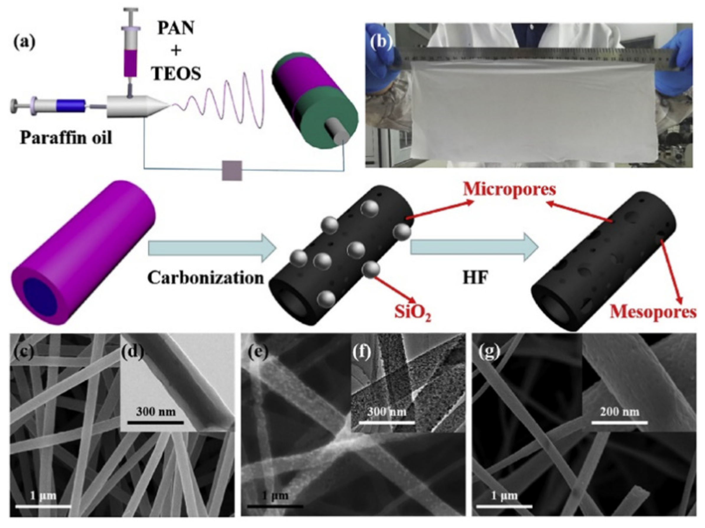
| PAN | DMF and paraffin oil | 0.9 g each in 10 mL | TEOS | 16 | - | 1000 in Ar | 205 ± 8 nm diameter and 3–7 nm mesopores | [87] |
| PAN | DMF | 500 mg in 5 mL | Graphene oxide nanoribbon/carbon nanotube | 20 | 250 | 700 in a reducing atmosphere (H2/Ar, 5%/95%, v/v) | 200–300 nm diameter (SEM) | [99] |
| PAN | DMF | 0.5 g in 5 mL | - | 18 | 300 | 900 in N2 and using PAN decomposition tail gas | 204 ± 26 nm | [100] |
| PAN | DMF | 3.5 g in 50 mL | Cellulose acetate | 55 | 280 in air | 800 in N2 | 200 to 500 nm (diameter) with channel rich structures (SEM) | [101] |
| PAN | DMF | 1.6 g in 10 mL | ZIF-8 cubic nanoparticles | 10.4 | 250 in air | 900 in N2 | Hollow carbon nanofibers with 500 nm diameter | [102] |
| PAA | DMA | 12 wt.% | Aniline | 18–25 | 100/200/300 | 1000 | 140–215 nm (diameter SEM) | [103] |
| PS | DMF | 25 wt.% | Dopamine | 12 | 60 in vacuum | 700 in Ar | 2–4 um diameter (SEM) | [104] |
| PAN and PVP | DMF | PAN: 10 wt.% and PVP: 8 wt.%) | Terephthalic acid (PTA) | 16 | 200–250 | 800 in N2 | 1–2 um diameter (SEM) | [105] |
| SF | water | 8 wt.% | - | 20 | 350 | 800 in N2 | 250 nm (diameter SEM) | [106] |
| PR | ethanol | 22 wt.% | Fe (acetylacetonate)3 | - | - | Up to 900 under NH3 | Abundant micropores and narrow mesopore size distribution (3–10 nm) | [107] |
| Growth Catalyst | Catalyst Film Deposition | Carbon Source | Thermal Decomposition (°C) | Additives | Morphology | Reference |
|---|---|---|---|---|---|---|
| Ni | Laser annealing of a thin nickel film obtained by electron beam sputtering | Ethylene | Ar ion laser operated at 488 nm | - | 12–47 nm diameter, disordered film | [109] |
| Co | Electrodeposition on pores of porous anodic aluminum oxide | Acetylene | 640 | - | 85 nm diameter in aligned CNF forest | [112] |
| Ni | Evaporation and sputtering on fused silica and silicon substrates | Ethane | 700 | - | 50–10 nm diameter, disordered film | [17] |
| Ni | Micropattern formation by direct photolithography | Acetylene | 600 | - | 20–40 nm diameter, aligned forests | [113] |
| Ni | 500 nm diameter circular dots photolithographically defined on Si wafer | Acetylene | Plasma enhanced at 700 | ammonia | conically shaped fibers of 6–20 μm length with tip diameters of 20–50 nm and base diameters of 500–600 nm | [114] |
| Ni | Ion beam coating of graphite paper with 22 nm thick Ni film | Acetylene | Plasma enhanced at 700 | ammonia | Uniform vertical alignment at 50 to 250 nm diameter | [115] |
| Ni | 100 nm diameter Ni spots using e-beam lithography | Acetylene | Plasma enhanced at 700 | ammonia | Conically shaped fibers with height of 1.5 μm, a base diameter of 100 nm, and a tip diameter of 70 nm | [116] |
| Ni | Ni/Ta thin film (25 nm/10 nm) by electron-beam evaporation | Ethane | 635 | - | Highly entangled morphology of CNFs, diameters in the range 10–100 nm | [117] |
| Pt | 2–10 nm film on n-type Si (100)/Ti (20 nm)/ta-C (7 nm) using cathodic arc deposition | Acetylene | Plasma-enhanced at 750 | ammonia | Vertically aligned fibers that were ~0.2–1 μm tall | [118] |
| Ni | Thin films of Ni (5 nm) over Pd (200 nm) with a Ti adhesion layer deposited by e-beam evaporation | Ethane | Pre-heated gas at 770 | - | Bidirectional growth of CNFs with embedded catalysts and diameters ranging from 70–160 nm with an average of 105 nm | [119] |
| NiFe | NiFe sputter deposited on silicon substrates pre-coated with Cr, W, Ti, or Ta metal buffer layers | Methane | Hot filament at 1900–2050 and substrate temperature: 650–750 | - | Un-aligned CNT | [120] |
| Ni | Electroplating | Methane | Hot filament at 1900–2050 and substrate temperature: 650–750 | - | CNF films | [120] |
| Fe | Gaseous Fe(CO)5 | Acetylene | 750 | - | Aligned CNT | [121] |
| Fe | Gaseous Fe(CO)5 | Methane | 1100 | - | Un-aligned CNT | [121] |
| Fe | In situ decomposition of ferrocene | Toluene | 550 and 940 | - | Aligned CNT from 590 °C and above until 940 °C, 10–70 nm diameter | [122] |
| Ni-Fe | Sputtering of Fe3Ni2 over Si wafer | Acetylene | 500 | - | 25 nm diameter | [123] |
| Ni-Cu | Sputtering of NiCu over Si wafer | Acetylene | 400 | - | 58 nm diameter | [123] |
| Pd-Se | Se deposited by effusion cell, Pd deposited by electron beam evaporation | Acetylene | 500 | - | 13 nm diameter, large number of defects | [123] |
Publisher’s Note: MDPI stays neutral with regard to jurisdictional claims in published maps and institutional affiliations. |
© 2020 by the authors. Licensee MDPI, Basel, Switzerland. This article is an open access article distributed under the terms and conditions of the Creative Commons Attribution (CC BY) license (http://creativecommons.org/licenses/by/4.0/).
Share and Cite
Restivo, J.; Gonçalves Pinto Soares, O.S.; Ribeiro Pereira, M.F. Processing Methods Used in the Fabrication of Macrostructures Containing 1D Carbon Nanomaterials for Catalysis. Processes 2020, 8, 1329. https://doi.org/10.3390/pr8111329
Restivo J, Gonçalves Pinto Soares OS, Ribeiro Pereira MF. Processing Methods Used in the Fabrication of Macrostructures Containing 1D Carbon Nanomaterials for Catalysis. Processes. 2020; 8(11):1329. https://doi.org/10.3390/pr8111329
Chicago/Turabian StyleRestivo, João, Olívia Salomé Gonçalves Pinto Soares, and Manuel Fernando Ribeiro Pereira. 2020. "Processing Methods Used in the Fabrication of Macrostructures Containing 1D Carbon Nanomaterials for Catalysis" Processes 8, no. 11: 1329. https://doi.org/10.3390/pr8111329
APA StyleRestivo, J., Gonçalves Pinto Soares, O. S., & Ribeiro Pereira, M. F. (2020). Processing Methods Used in the Fabrication of Macrostructures Containing 1D Carbon Nanomaterials for Catalysis. Processes, 8(11), 1329. https://doi.org/10.3390/pr8111329