Article

The Effects of Different Slurry Concentrations and Wire Speeds for Swinging and Non-Swinging Wire-Saw Machining

1
Department of Mechanical Engineering, National Taiwan University, Taipei 10617, Taiwan
2
Department of Mechanical Engineering, Lunghwa University of Science and Technology, Taoyuan 33306, Taiwan
*
Authors to whom correspondence should be addressed.
Processes 2020, 8(10), 1319; https://doi.org/10.3390/pr8101319
Submission received: 10 September 2020 / Revised: 7 October 2020 / Accepted: 12 October 2020 / Published: 20 October 2020
(This article belongs to the Section Advanced Digital and Other Processes)

Abstract

:
Slurry concentration and wire speed affect the yield and machining quality of ceramics (Al2O3) that are produced using wire-saw machining (WSM). This study determines the effect of slurry concentration and wire speed on the material removal rate (MRR), the machined surface roughness (SR), the kerf width, the wire wear and the flatness for swinging and non-swinging WSM. The experiments show that swinging WSM results in a higher machining efficiency than non-swinging WSM. WSM with swinging also achieves a peak MRR at a medium slurry concentration (25 wt%) and a higher wire speed (5.6 m/s) using the cutting conditions for the experimental region. However, slurry concentration and wire speed have no significant effect on the machined SR, the kerf width, the wire wear or the flatness for WSM with swinging mode.

Graphical Abstract

1. Introduction

Precision ceramics are used in a wide range of various advanced applications in the semiconductor and optoelectronics industries. Precision ceramics feature superior thermal resistance, wear resistance and corrosion resistance, and are lightweight, which gives them an advantage over metal. The development of precision ceramics will increase performance for the most advanced industries in the future. However, precision ceramics have a lower resistance to fracture than metals, which often undergo plastic deformation during machining, so the machined surface is marked with fractures in the form of extended minute cracks. It is difficult to control both machining precision and machined surface roughness (SR).
Ceramic is a key component in the semiconductor and optoelectronics industries. The slicing machining process for ceramics must be low cost, involve a short machining time, feature minimum loss of kerf and produce a good quality machined surface. A wire-saw uses abrasive cutting for the machining of hard, brittle materials and is efficient for cutting ceramics. WSM uses stainless steel wires to mobilize abrasive slurry and cut hard, brittle materials. A stainless steel wire for WSM can have a single or multiple strands. WSM dissipates less heat during machining, so there are small disturbed layers on the workpiece surface. An extremely fine slot is cut (wire diameter of 0.25 mm or even smaller) so there is less waste of machined materials. Similarly to a polishing process, WSM achieves good surface roughness if the cutting conditions are controlled. However, wire-saw machines can be less structurally rigid than conventional cutting machines.
There have been many experimented studies of WSM using various process parameters [1,2,3]. Teomete [1] showed that the material removal mechanism is related to trans-granular failure of the grains and inter-granular fractures within grains affect the surface quality. Lee et al. [2] showed that the break-in characteristics of diamond wire are strongly correlated with the wear behavior of diamond wire for single WSM. Qiu et al. [3] showed that process parameters, such as the magnetic field intensity, the feed rate for the workpiece, the running speed for the wire, the viscosity of the cutting fluid and the mass fraction of the magnetic abrasive grains, affect the cutting performance of a free abrasive. Bao et al. [4] noted that localized porous features are generated on the surface of the anodic oxide layer if multi-crystalline silicon ingots are sliced into wafers using abrasive electrochemical multi-wire sawing because the original surface undergoes anodic oxidation.
The total volume that is removed and the slicing efficiency for a brazed wire saw that uses different slicing parameters (diameter of wire-saw, diamond grain and diamond concentration) are respectively 2.2- and 1.5-times better than that for an electroplated wire-saw [5]. Li et al. [6] proposed a constant wire wear loss model, which gives good wafer quality and consumes 24.8% less wire than a conventional method for specific slicing parameters (length of ingot, wire speed, table feed speed, wire forward length and radius of ingot). Liu et al. [7] showed that the feed rate and the wire speed have a different effect on the depth of cut and the cutting force for resin-bonded diamond wire-sawing. WSM gives an increased MRR and decreased wire wear. The machined surface roughness, the kerf width and the flatness are indicators of the quality of WSM. Yeh et al. [8] showed that diamond wear increases as the bonding layer thickness decreases because grains protrude less as the thickness of the electroplated nickel layer increases, especially if the cutting speed and feed rate are increased for wire-sawing of sapphire ingots.
Hsu et al. [9] used the grey-Taguchi method to optimize the qualities of WSM (MRR, surface roughness, steel wire wear, kerf width and flatness) for ceramics using ultrasonic-assisted vibration. Clark et al. [10] used a capacitance sensor to measure the bow in the wire and converted the bow to a vertical cutting force for swinging WSM. Huang et al. [11] noted that the contact length changes significantly in one half of a swing period for wire-sawing with swinging using a square or circular ingot. Chen and Gupta [12] showed that a swinging motion decreases the contact length and the equivalent chip thickness by 50% for wire-sawing of a mono-crystalline alumina oxide wafer. Xu et al. [13] determined that the amplitude of the swing of the ingot for multi-wire sawing of mono-crystalline silicon wafers has no significant effect on the contact wire length but has a significant effect on the ingot feed speed. It was shown that a swinging amplitude for the ingot of 5° gives the best quality machined surface for WSM with swinging. This study determines the effect of machining parameters (slurry concentration, wire speed, swinging frequency and swinging angle) on the machining characteristics (MRR, roughness of the machined surface, kerf width, wire wear and flatness) for WSM with swinging.

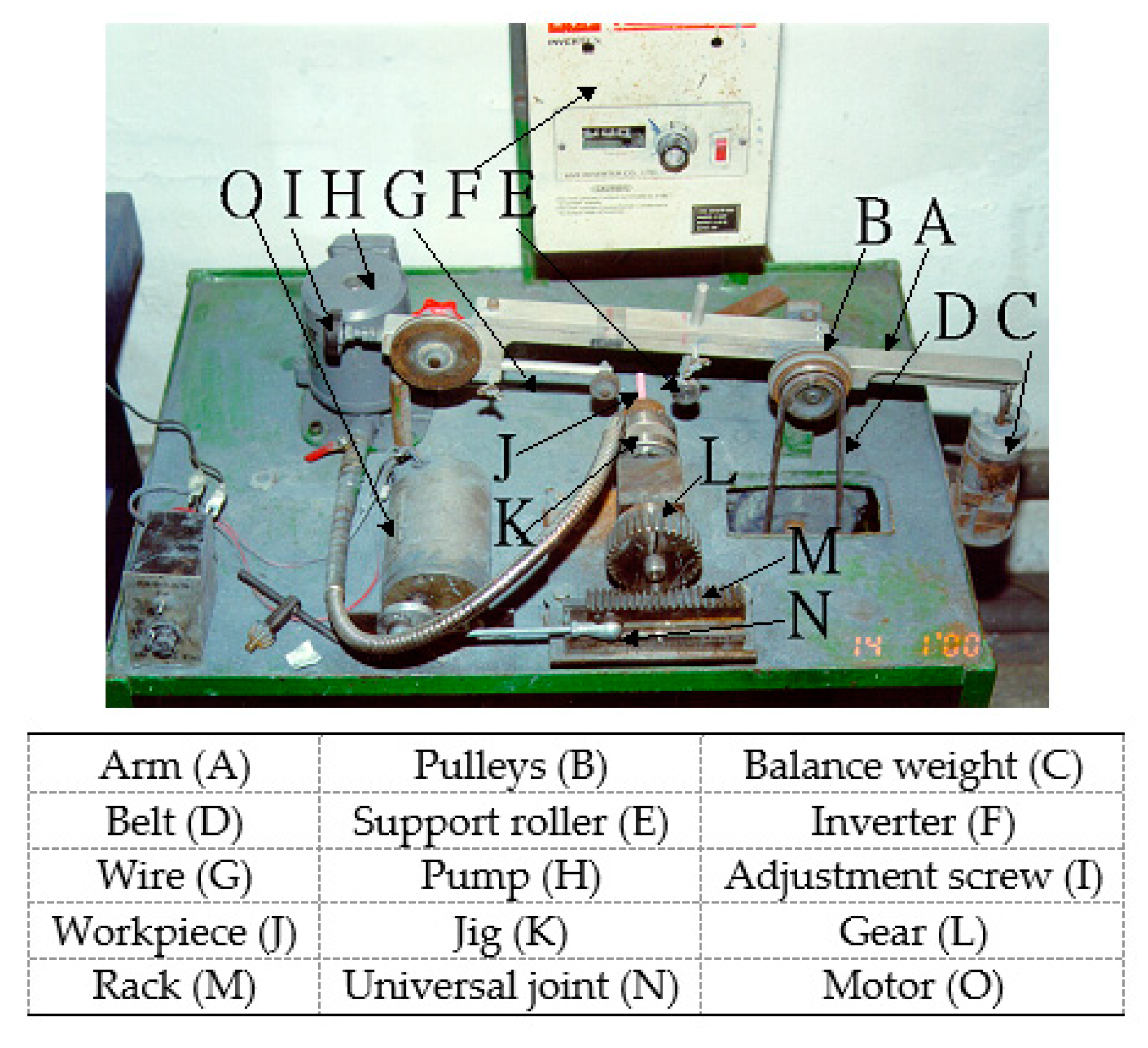
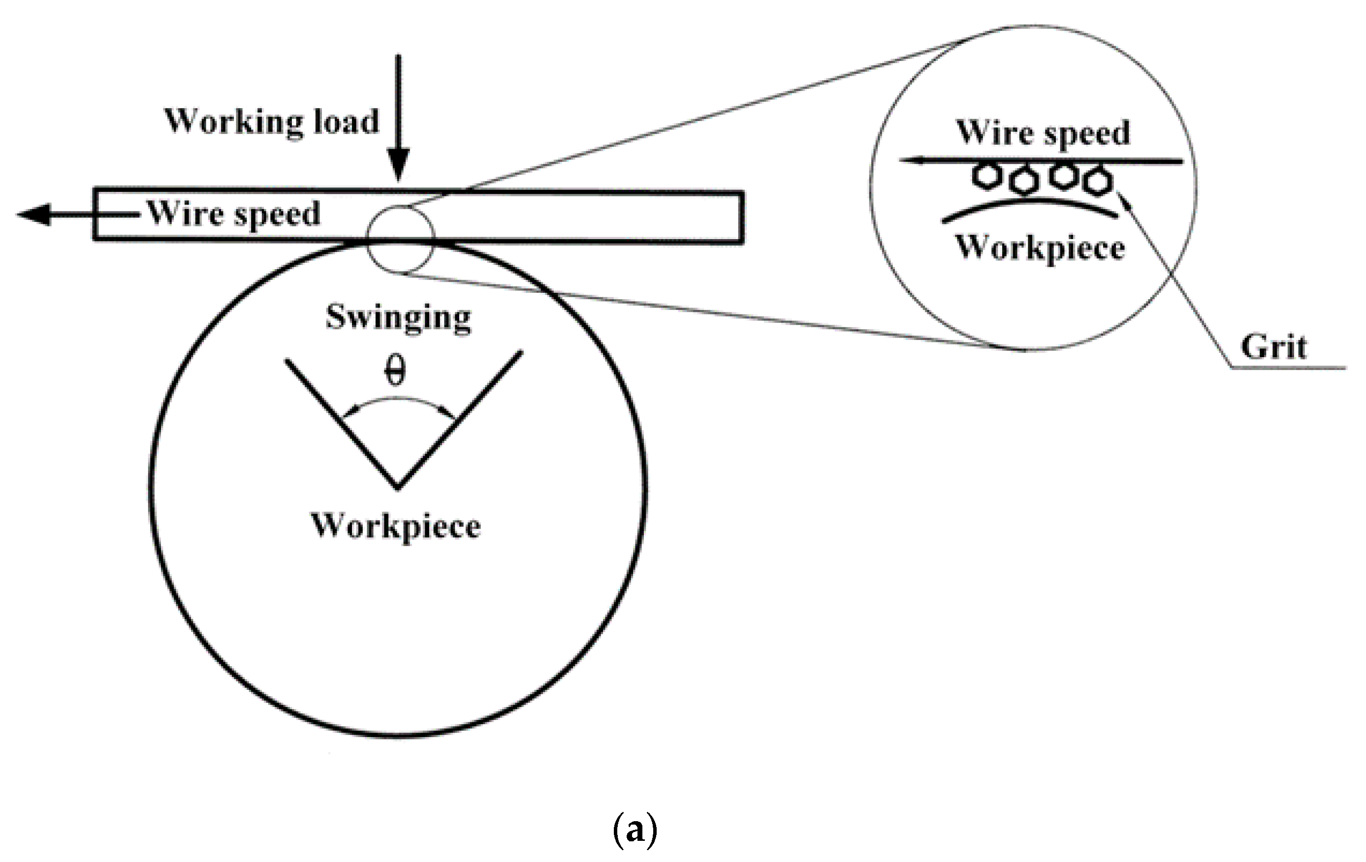
2. Experimental Apparatus and Methodology

Figure 1 shows the experimental setup for the single wire-sawing system that is used for this study. The inverter (F) and the position of the belt (D) for the pulley (B) were adjusted to control the wire speed. The adjustment screw (I) was adjusted to achieve the proper wire (G) tension. The working load was varied by adjusting the balance weight (C) on the arm (A). A pump (H) was used to stir and supply slurry. The workpiece (J) was fixed to a jig (K). The motor (O) drives the rack (M) through a universal joint (N). The rack moves back and forth and drives the gear (L), which rotates in the same direction (gear (L)) and shares the same central shaft as the jig (K).
Figure 2a shows that the workpiece (J) swings back and forth. Figure 2b shows the length of contact between the wire and the workpiece during WSM. This swinging machining model exerts a uniform cutting force on each active grain and allows efficient disposal of chips. The main experimental conditions are listed in Table 1, wherein the slurry concentration is shown as a percentage of the weight of the slurry grain (weight of grain/weight of slurry as a whole). The MRR and wire wear (WW) for each SWSM is calculated using Equations (1) and (2), which are defined as follows:
M R R = W I W W t
W W = D I D W t
where W I is the original weight before SWSM and W W is the actual weight after SWSM, D I is the original diameter before SWSM, D W is the diameter after SWSM and t is the period for SWSM. A tool microscope (Nikon, MM-40, Tokyo, Japan) acts as an optical ruler to accurately measure the wire wear to an accuracy of 1 μm. A tension meter (IMADA, DPRSX-10TR, Toyohashi, Japan) was used to measure the wire tension and working load. The surface morphology was determined using field emission scanning electron microscopy (JEOL JSM-6300 SEM, Tokyo, Japan).

3. Experimental Results and Data Analysis

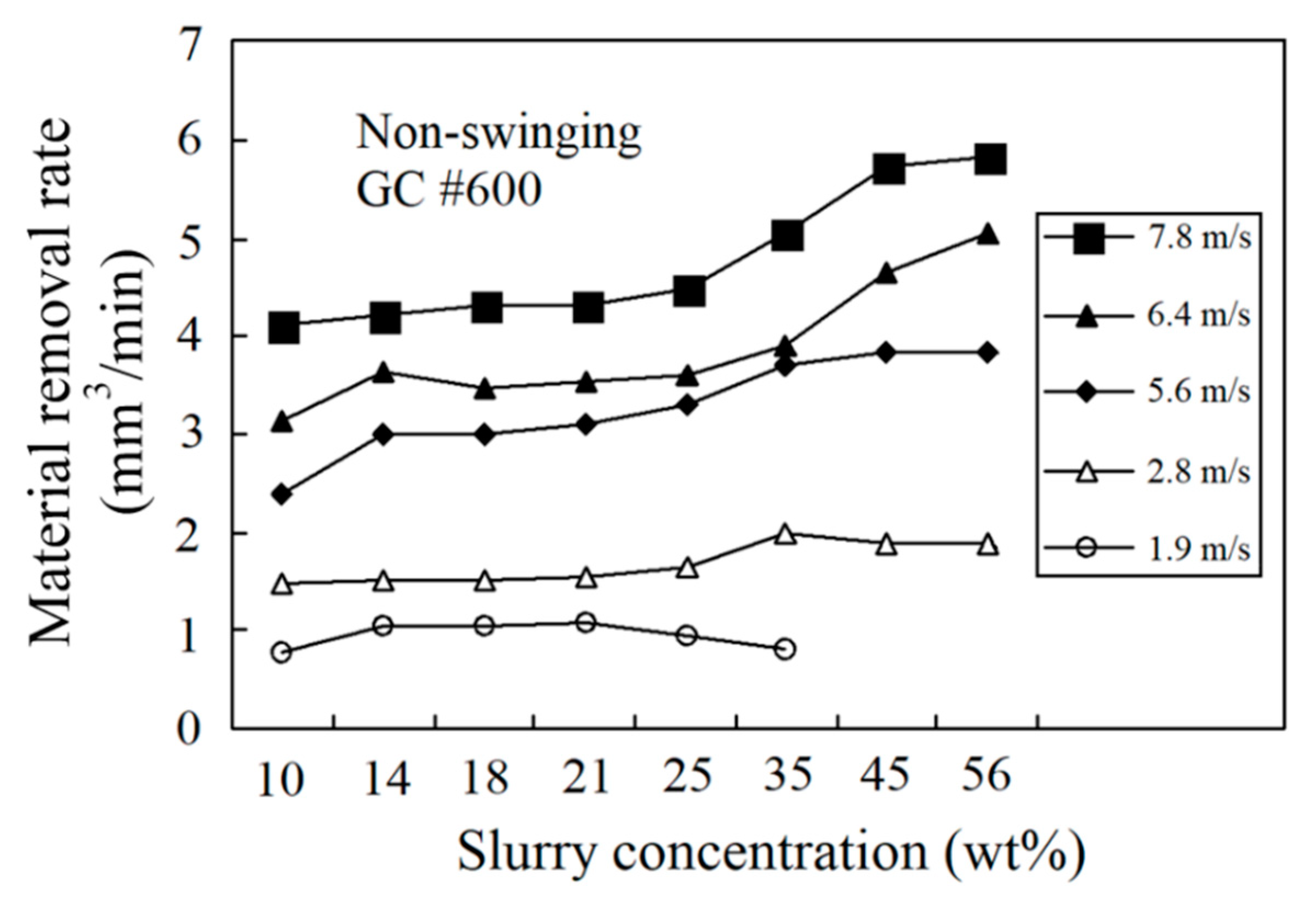
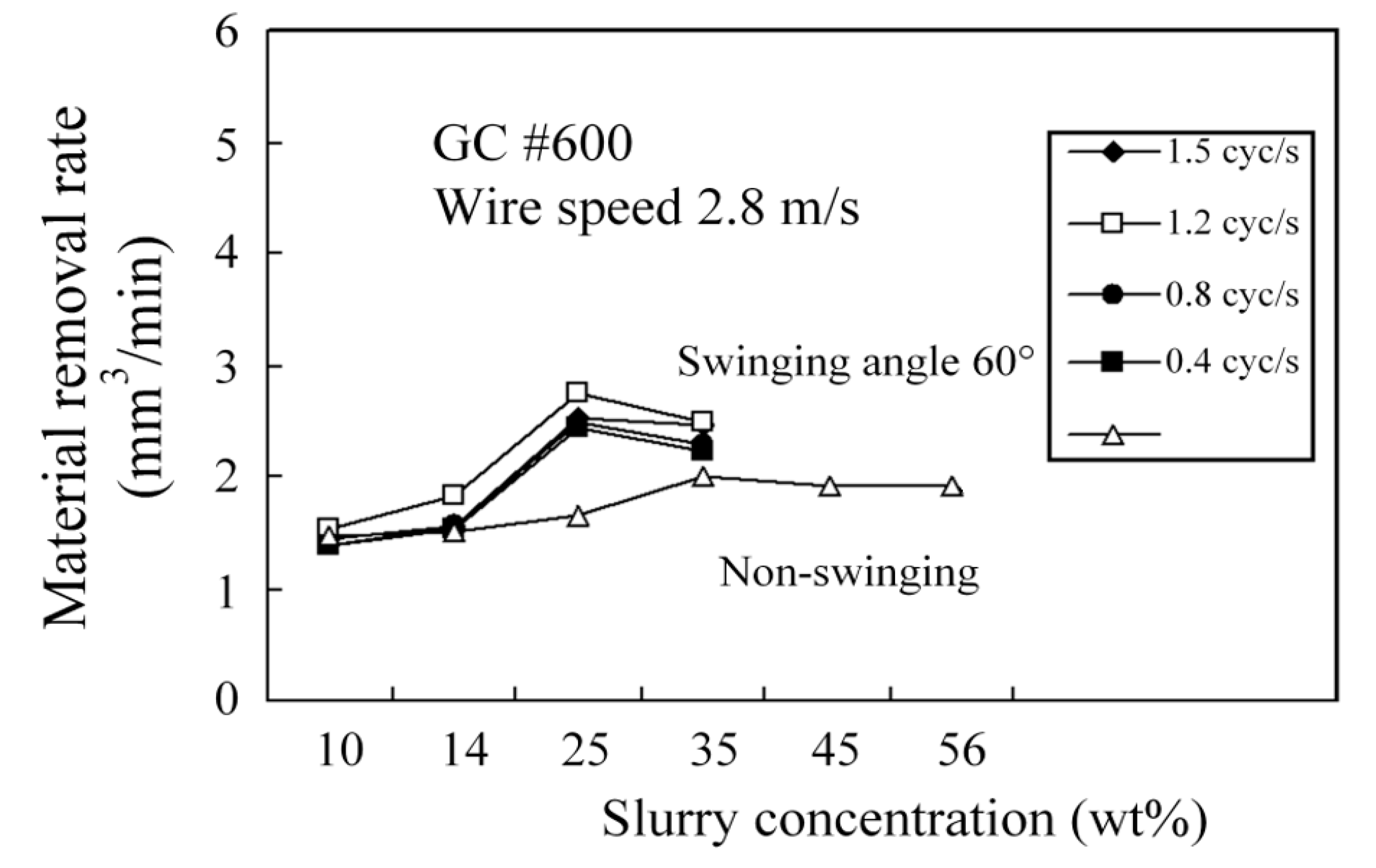
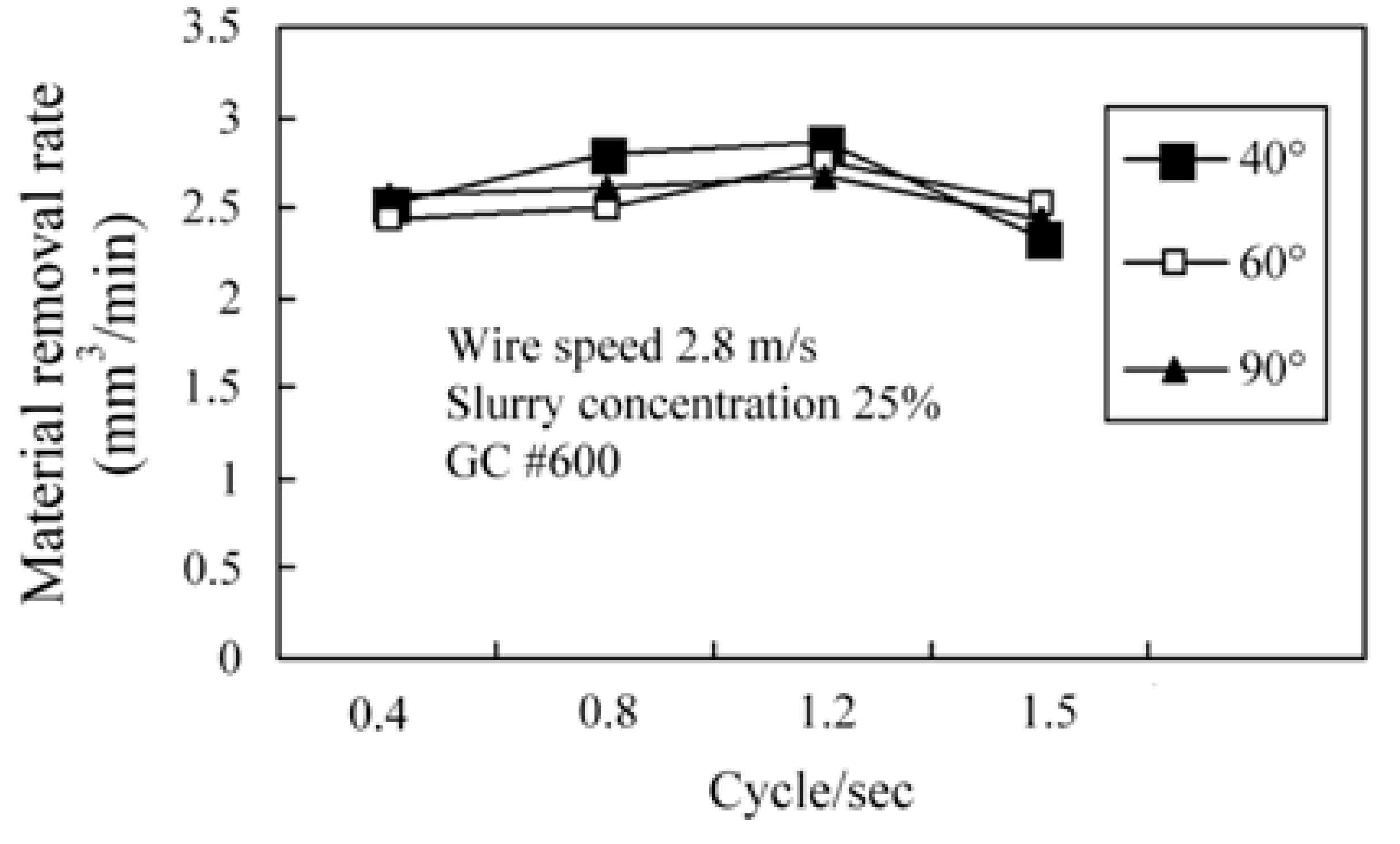
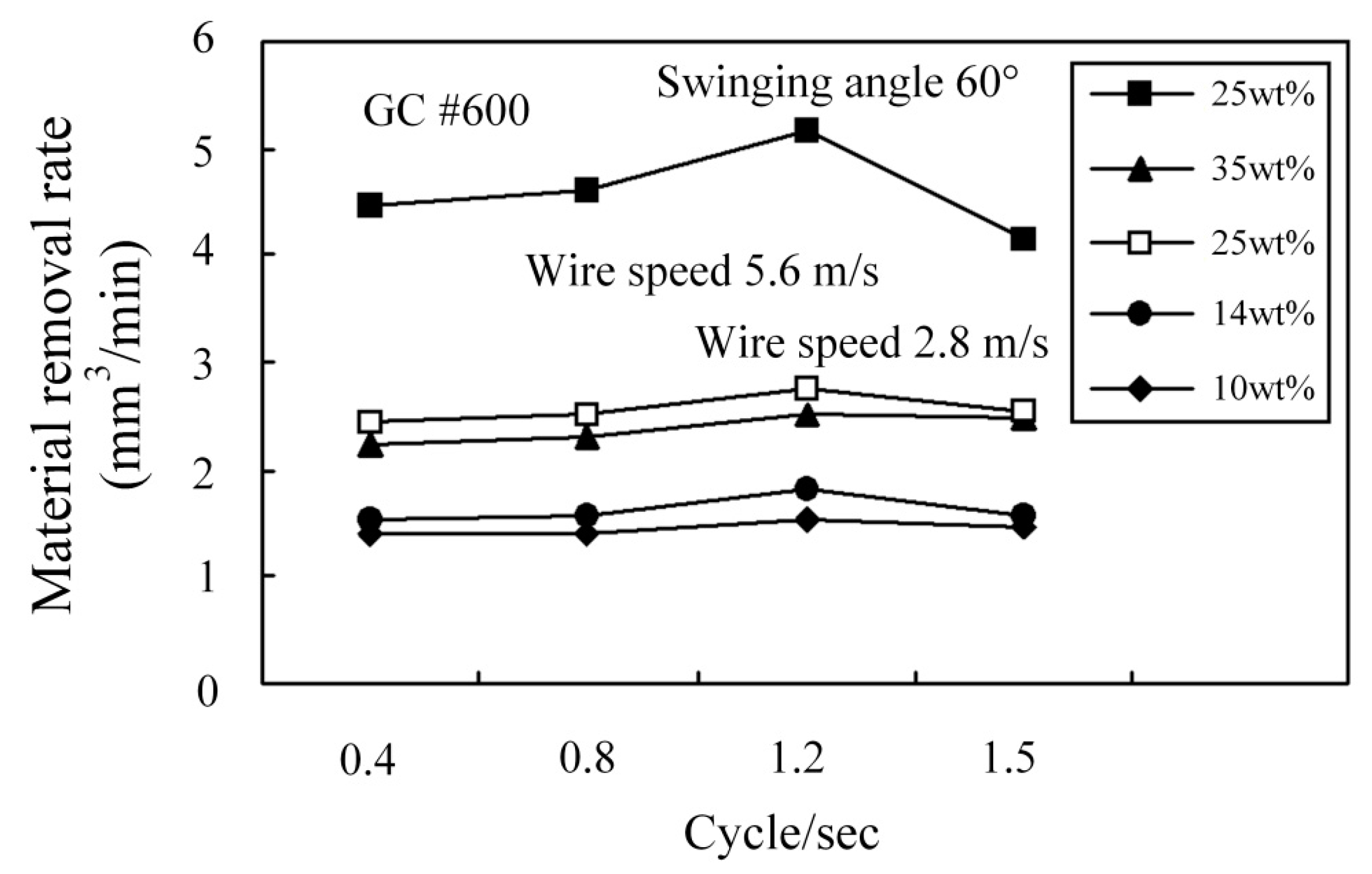
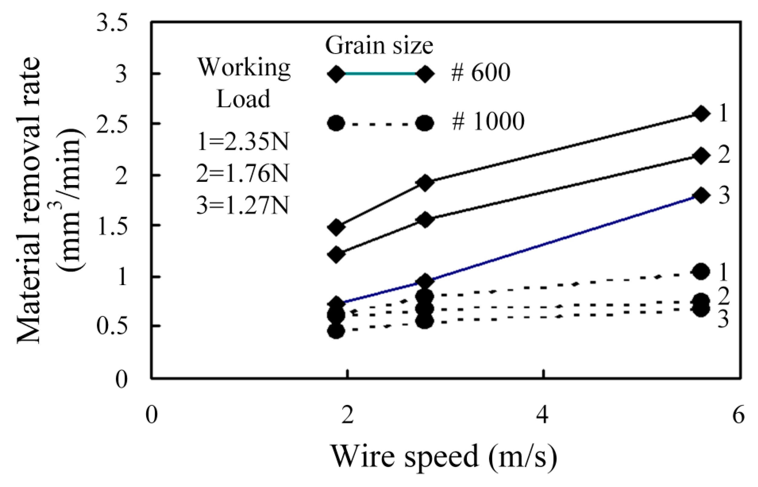
3.1. Effect of Machining Parameters on MRR

The wire speed and slurry concentration are directly related to MRR for WSM. Figure 3 shows the experimental results for MRR for a non-swinging scenario for different wire speeds and slurry concentrations. The peak MRR is achieved at a higher slurry concentration and a higher wire speed. As the wire speed increases, the peak MRR is only achieved by increasing slurry concentration. This demonstrates that material is almost exclusively removed by the active grains in the slurry. The greater the slurry concentration, the greater is the number of active grains, so there is an obvious increase in the MRR. At a lower wire speed, active grains are removed more slowly from the machining zone so increasing the wire speed results in a greater MRR from the machining zone for a non-swinging scenario.
Figure 4 shows the relationship between swinging frequency, slurry concentration and MRR for swinging and non-swinging scenarios. The MRR is greatest at a swinging frequency of 1.2 cycle/s (Hz) because this swinging frequency allows active grains to enter and exit at a wire speed of 2.8 m/s and a slurry concentration of 25%. The contact between the wire and the workpiece for the swinging scenario is shorter than that for the non-swinging scenario, so each active grain produces a larger cutting force (or cutting pressure). The active grains also enter and exit the machining zone faster and there is more efficient disposal of chips for WSM. Therefore, WSM with swinging produces a higher MRR for a specific wire speed and slurry concentration.
Figure 5 shows the effect of the swinging angle and frequency on the MRR for swinging WSM. The results show that swinging angles of 40°, 60° and 90° have no significant effect on the MRR. Figure 6 shows that the MRR is significantly increased at a swinging angle of 60° and a grain size of GC #600 if a higher wire speed is used. At a higher wire speed, active grains are removed more quickly from the machining zone. However, if there are only fine GC #1000 grains in the slurry, the MRR is significantly reduced, as shown in Figure 7. If only large GC #600 grains are used, these larger grains are not properly suspended in the slurry so they deposit in the slurry and are transferred to the cutting zone by the wire, so machining efficiency is better than that for fine GC #1000 grains. The MRR for GC #600 and GC #1000 grains increases if the working load is increased, as shown in Figure 7. The MRR for fine GC #1000 grains is between 0.5 to 1.0 mm3/min because there is a smaller plowing force for specific wire-sawing conditions than for large GC #600 grains.

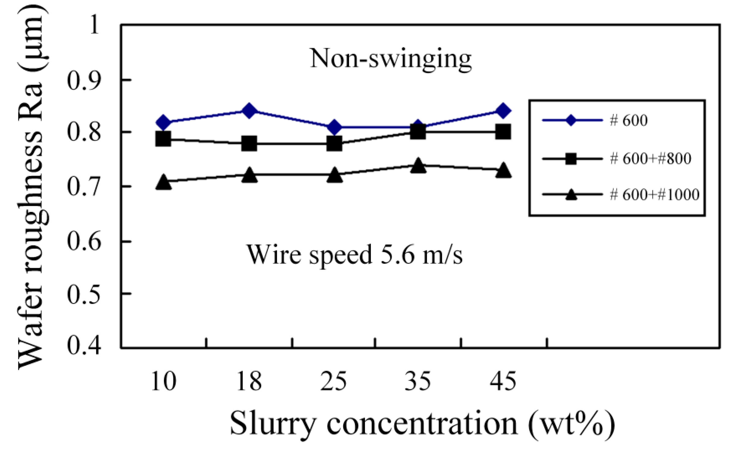
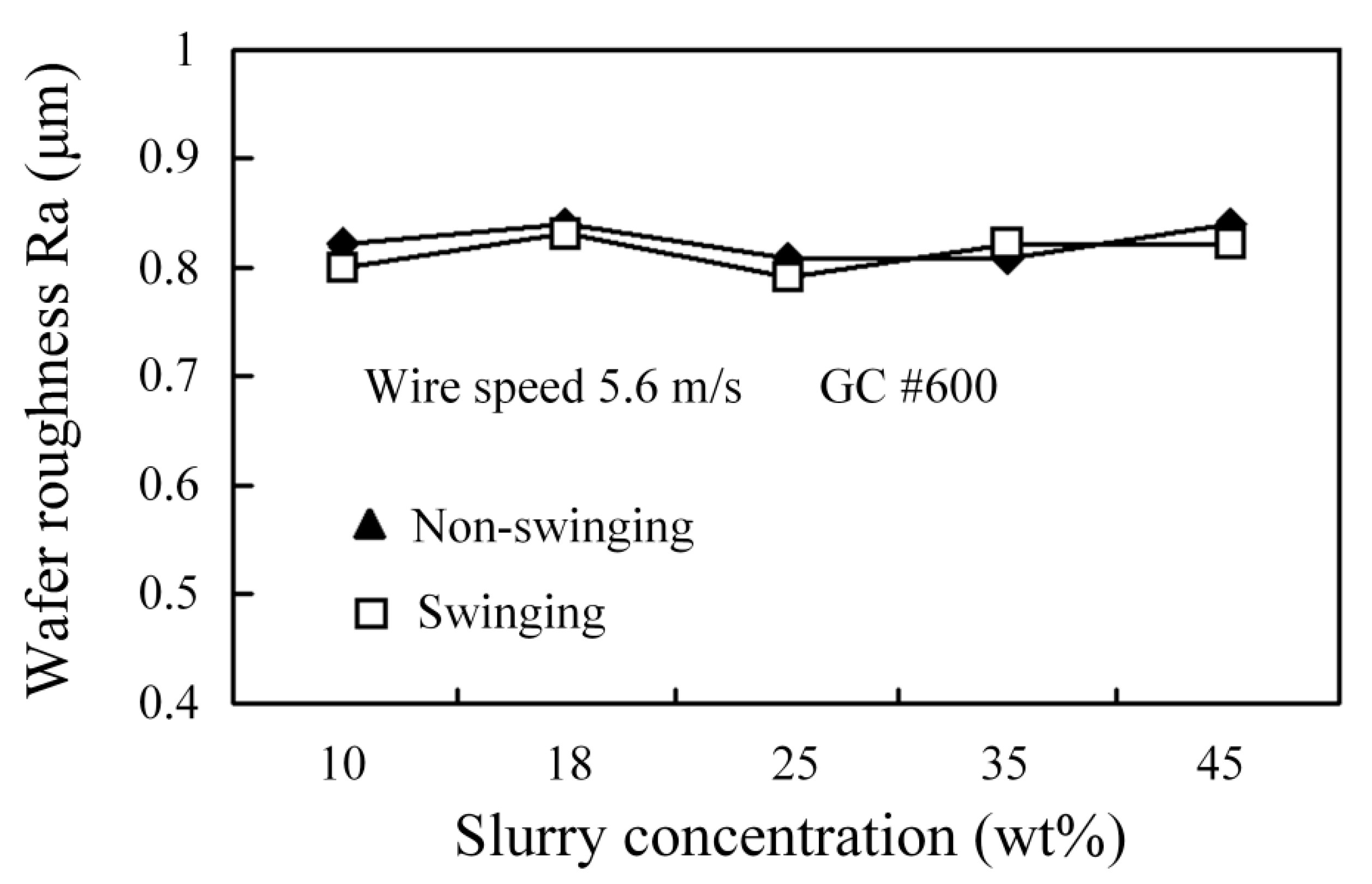
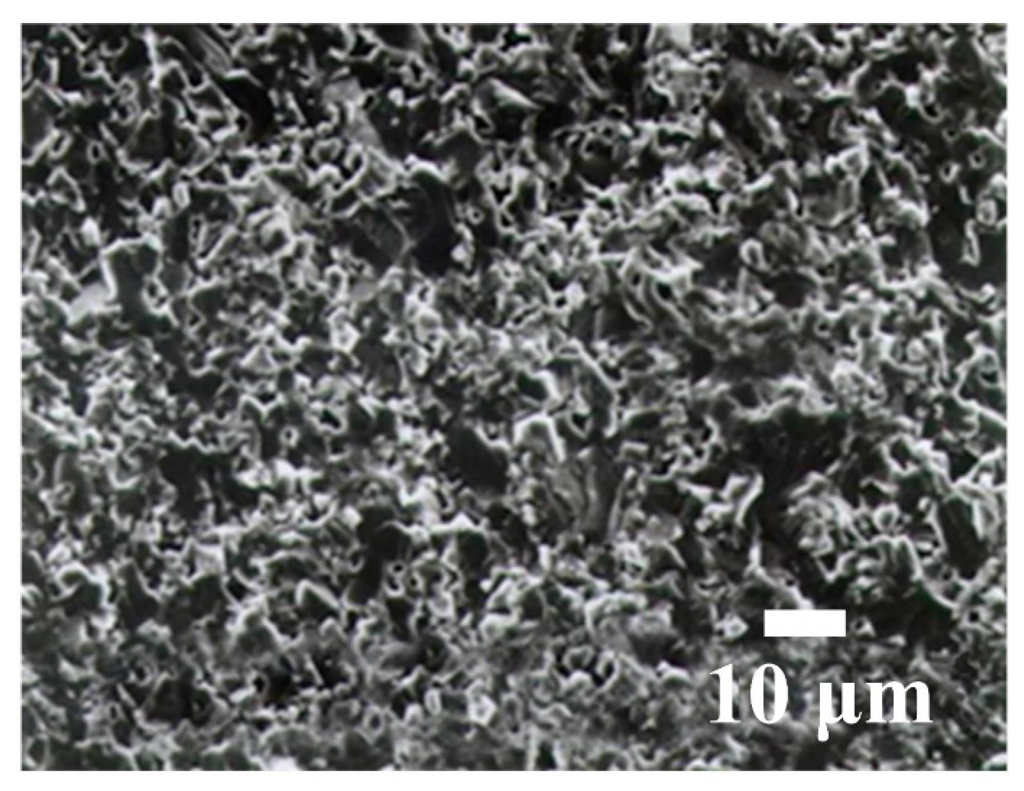
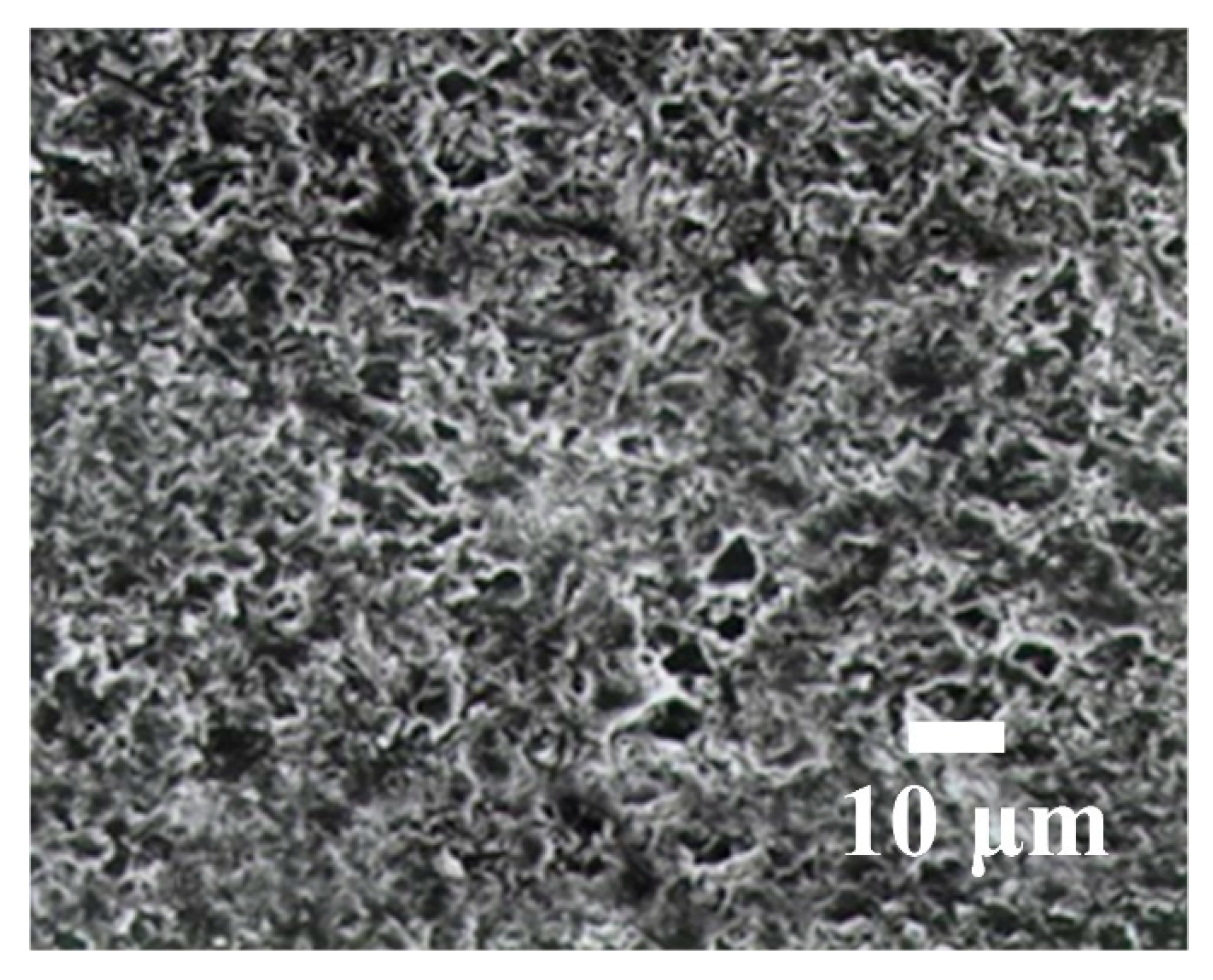
3.2. Effect of Machining Parameters on the Machined SR

During WSM, each grain in the cutting zone exerts a cutting force that is similar to that for a polishing process, so an increase in the working load and wire speed has no effect on the machined SR. If larger grains are used, more material is removed by a single grain so the machined SR is rougher and larger cutting marks remain. Figure 8 shows that the addition of small grains into the slurry decreases the machined SR of Al2O3 and an increase in the slurry concentration has no significant effect on the machined SR of Al2O3. Figure 9 shows that there is no significant difference in the machined SR for swinging and non-swinging scenarios. Figure 10 shows that the fracture cross section for Al2O3 is rougher. Figure 11 and Figure 12 respectively show the machined surface after WSM using a slurry of green silicon carbide (GC), with and without swinging. There are no clear cutting marks because the slurry produces an abrasive plowing force that is similar to that for a polishing process. Figure 13 shows the machined surface for wire-sawing using a fixed abrasive (diamond). Clear cutting marks are seen and the machined surface of the Al2O3 is also rougher. Diamond wire is very expensive and the diamonds on the stainless steel wire are easily lost, which renders the stainless steel wire incapable of machining, so GC cutting is not practical.
Figure 14 shows a SEM microphotograph of Al2O3 if no slurry is used. The energy-dispersive spectrometer (EDS) result for zone A (in Figure 14) is shown in Figure 15 and shows the microstructure of stainless steel, which contains Fe, Cr, Ni, and Si. If there is no slurry, the wire has no machining capability, so it becomes welded onto the workpiece surface.

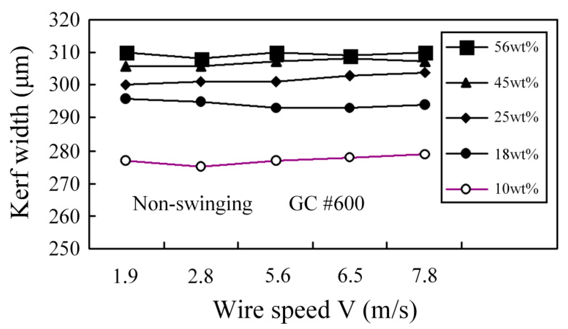
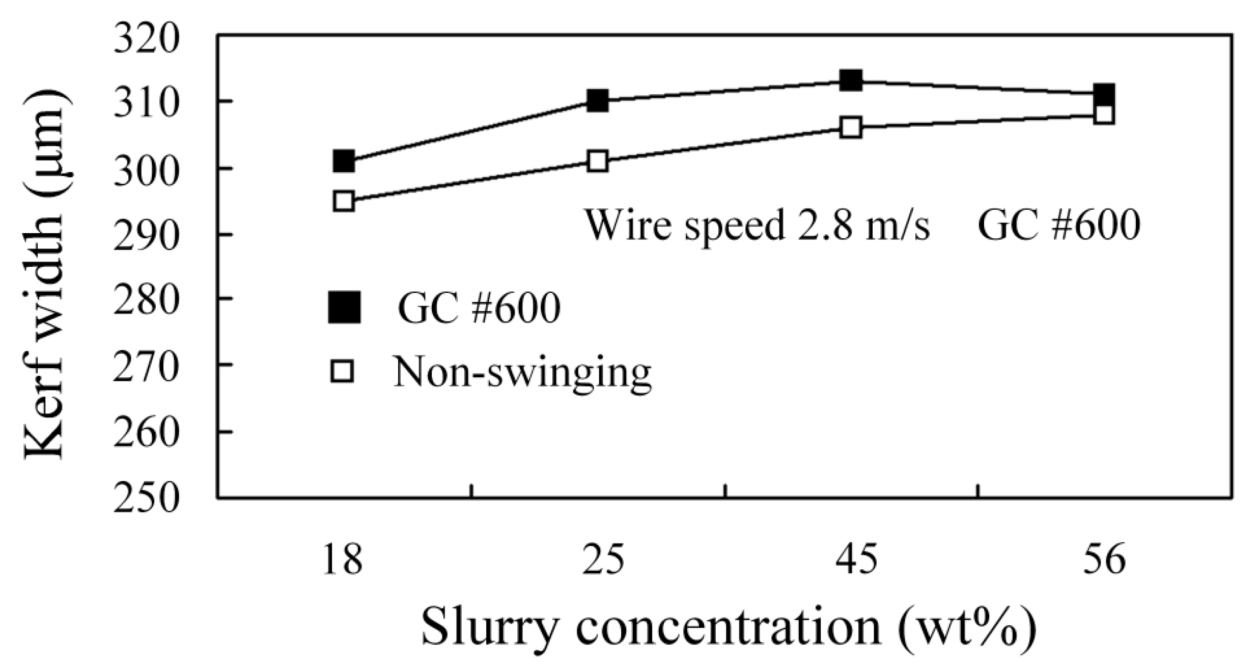
3.3. Effect of Machining Parameters on Kerf Width

Figure 16 shows the experimental results for different wire speeds and concentrations. Increasing the wire speed has no significant effect on the kerf width. As the concentration increases, the number of grains that enters both sides of the stainless steel wire increases so the kerf is wider. Figure 17 shows that there is only a slight difference in the kerf width for swinging and non-swinging WSM. However, WSM with swinging produces a wider kerf than non-swinging WSM.

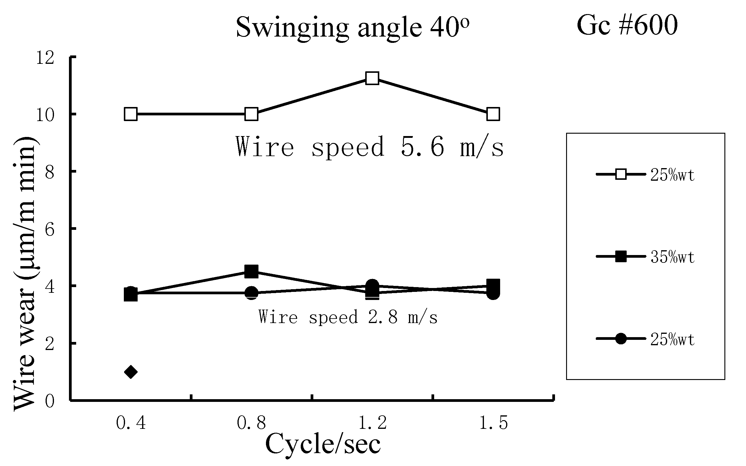
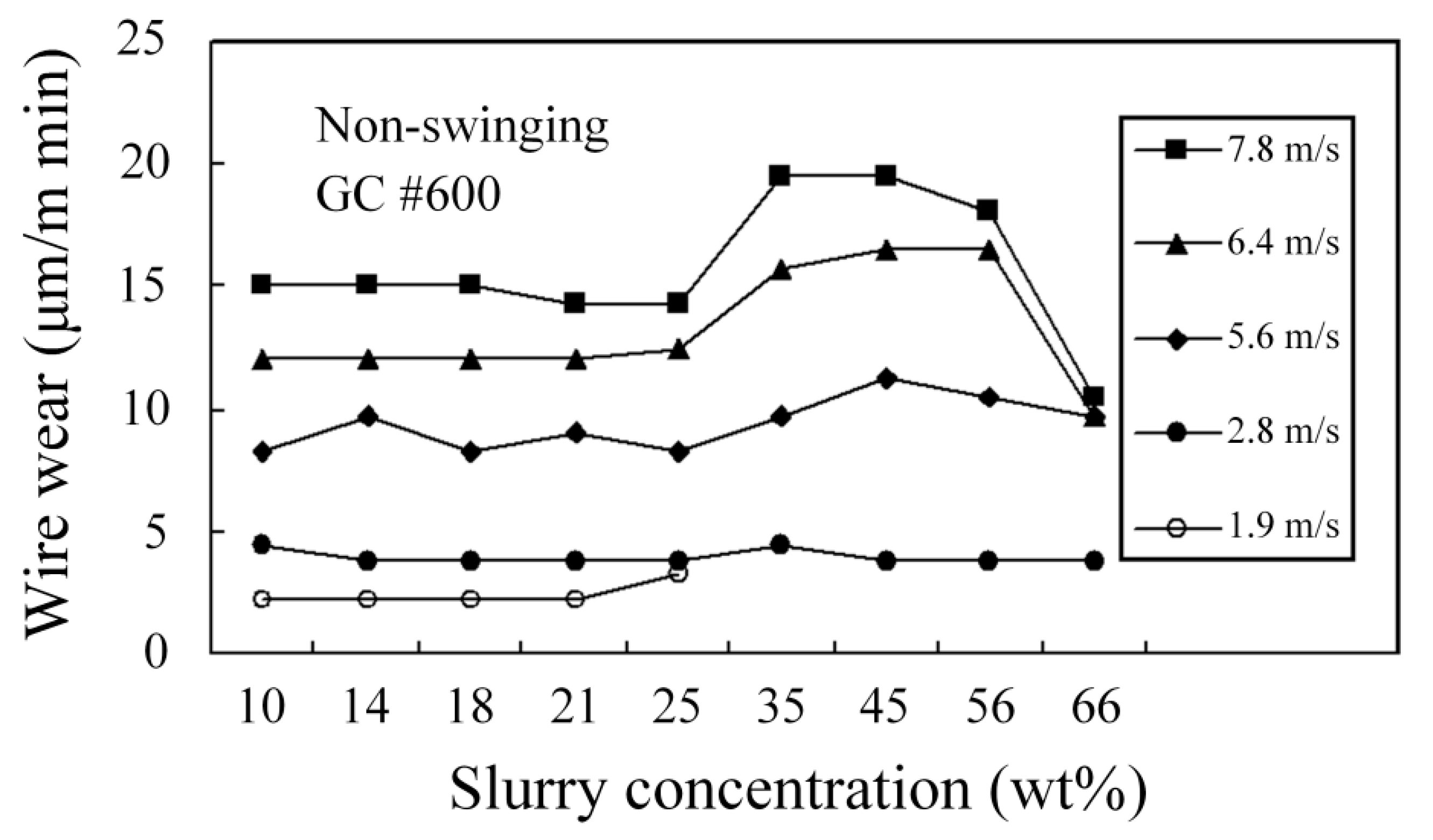
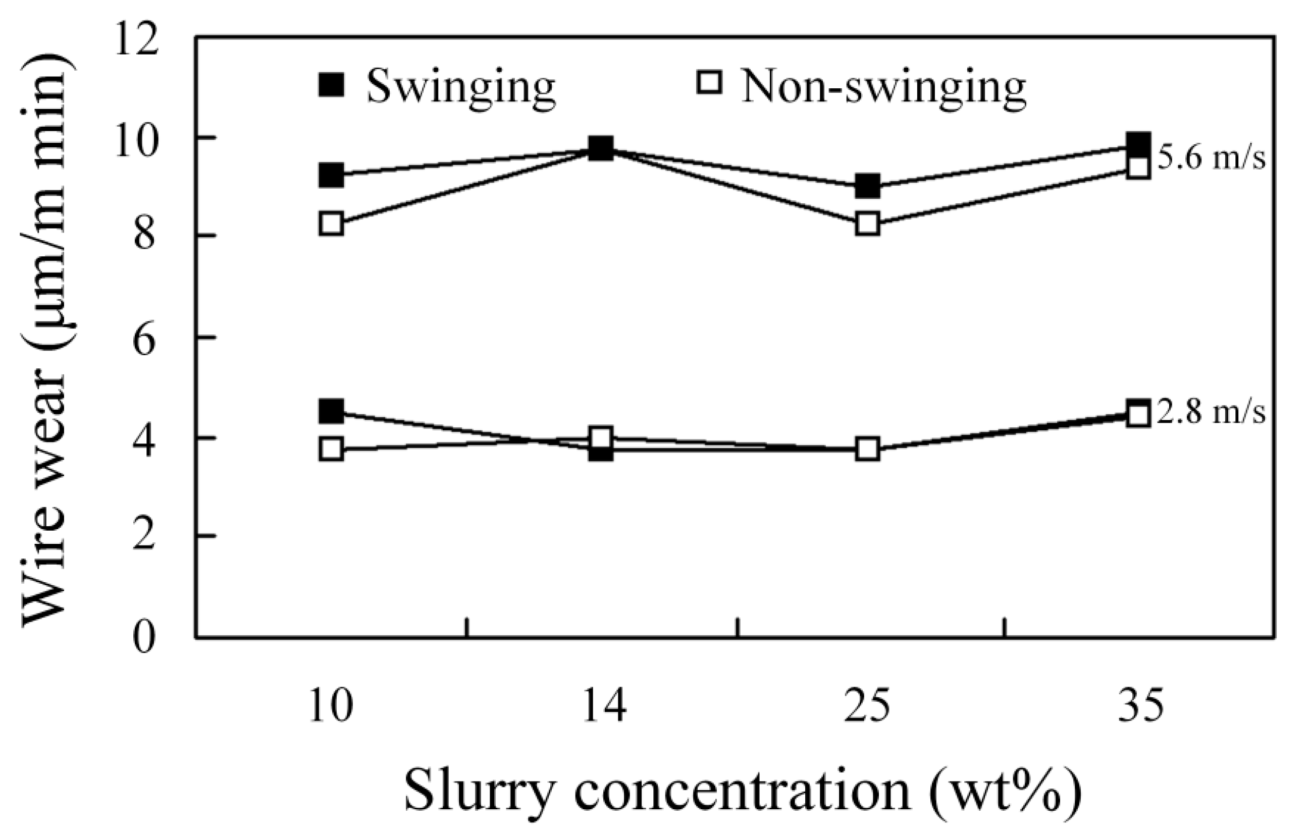
3.4. Effect of Machining Parameters on the Wear to Stainless Steel Wire

The degree of wire wear affects the life of the wire and the kerf width for WSM. If the working load and wire speed are increased, wire wear increases significantly because the distributed stresses (working load) that act on the stainless steel wire are more complicated and more time is required to complete WSM. If the wire speed is increased, the grains also enter and exit the cutting zone more quickly so more grains are involved in the cutting process and the wire wears more quickly, as shown in Figure 18. Wire wear is positively correlated with the MRR because the grains cut the wire as they remove material from the workpiece. A slurry concentration that gives the best MRR also produces greater wire wear. Figure 19 shows that there is no significant difference in wire wear for swinging and non-swinging processes. Figure 20 shows that for specific swinging conditions, a higher wire speed results in a significant increase in wire wear.

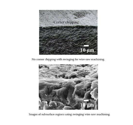
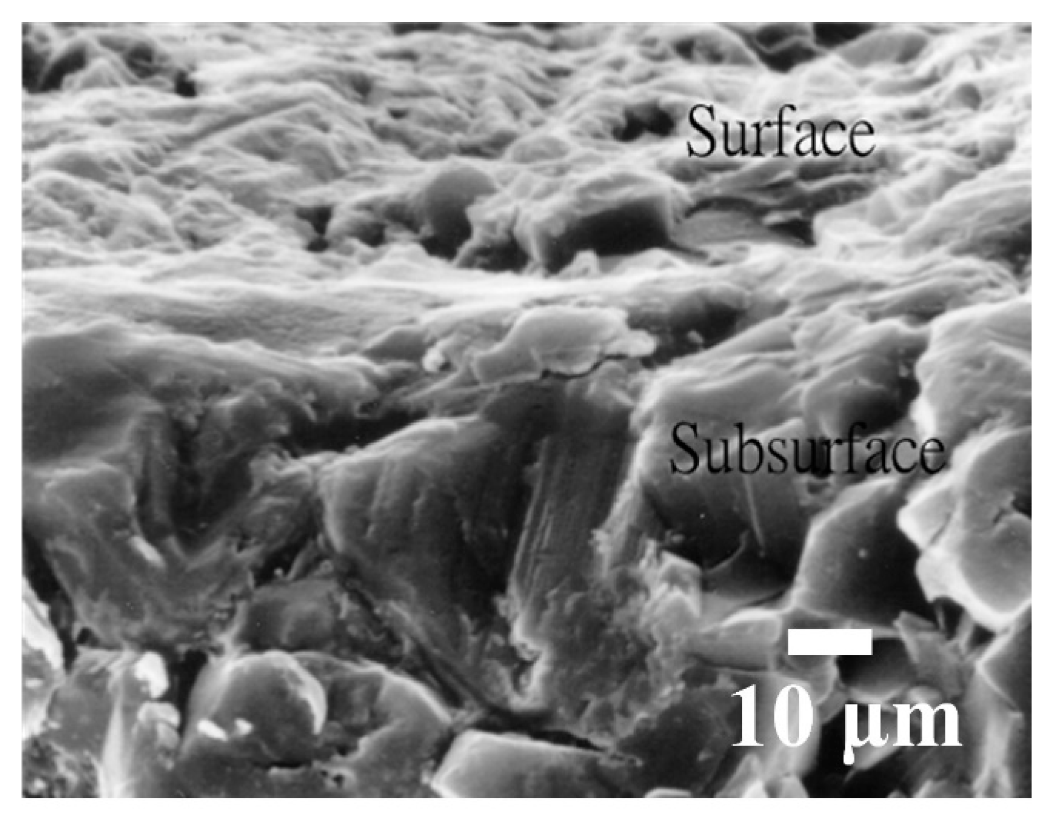
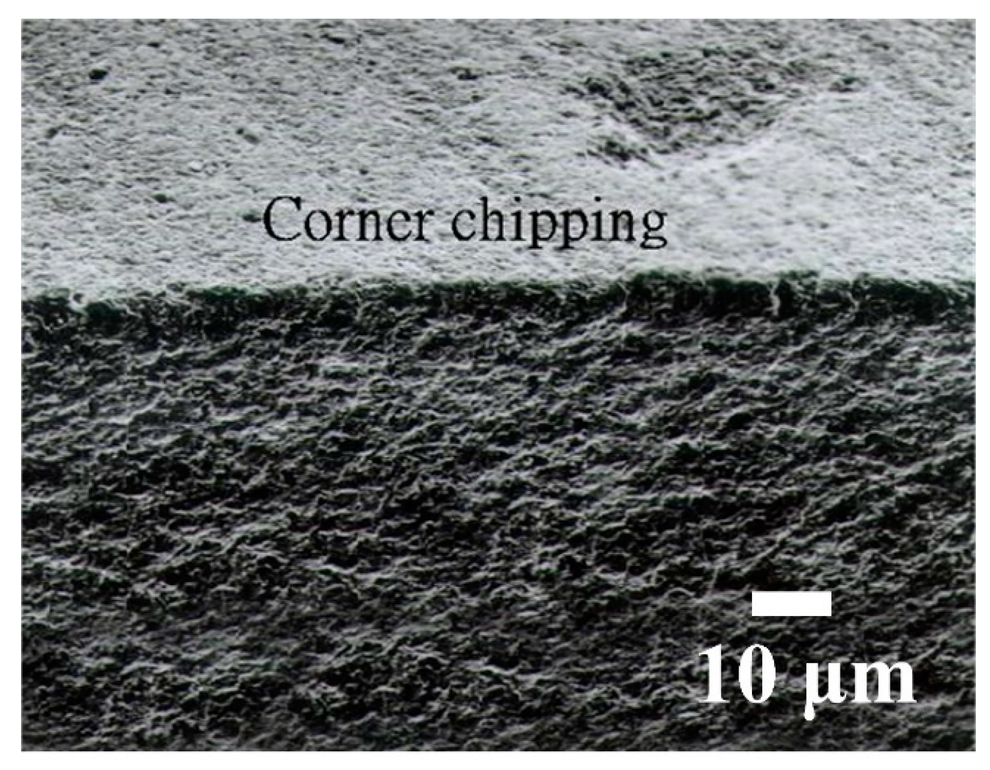
3.5. Effect of Machining Parameters on Flatness, Corner Chipping and Micro Cracking

Swinging WSM (the flatness about 2–4 μm) has no significant effect on flatness. Figure 21 shows that there is no corner chipping for WSM. Figure 22 shows SEM images of subsurface regions of Al2O3 after WSM. There is no evidence of micro cracking after WSM.

4. Conclusions

For a process that involves swinging, there is no decrease in the working load that is exerted by each active grain and less time is required for grains to enter and exit the cutting zone. The disposal of chips is also more efficient. WSM with swinging results in a higher MRR. If many active grains enter the cutting zone, grain stacking and interference prevent the grains from moving so the MRR is decreased. The cutting zone for a process that involves swinging is shorter than that for a process that does not involve swinging, so grain stacking and the peak MRR are achieved at a medium slurry concentration.
Swinging angles of 40°, 60° and 90° do not significantly affect the MRR. If only fine grains are present in the slurry, such as GC #1000 grains, the MRR is very small. If large GC #600 grains are used, these larger grains are not suspended in the slurry, so they are deposited in the slurry and are brought into the cutting zone by the wire, which gives better machining efficiency than is possible for fine GC #1000 grains.
WSM has a similar effect to a polishing process so machining conditions have no significant effect on the machined SR of Al2O3. An increase in slurry concentration results in a significant increase in kerf width and an increase in MRR. However, there is also a slight increase in wire wear for WSM. As the grains remove parts of the workpiece, they also cut the wire. For a slurry concentration that produces a peak MRR, the wire also wears down quickly. This study shows that there is no significant difference in wire wear, flatness, corner chipping or micro cracking between processes that involve swinging and non-swinging WSM.

Author Contributions

Conceptualization, Y.-Y.T. and Y.-C.C.; methodology, Y.-S.L.; software, Y.-S.L.; validation, C.-C.H., Y.-Y.T. and Y.-C.C.; formal analysis, C.-C.T.; investigation, C.-C.T.; resources, C.-Y.H.; data curation, C.-Y.H.; writing—original draft and preparation, C.-Y.H.; writing—review and editing, C.-C.T.; visualization, C.-C.T.; supervision, Y.-Y.T.; project administration, Y.-Y.T.; funding acquisition, Y.-Y.T. All authors have read and agreed to the published version of the manuscript.

Funding

This research was funded by the Ministry of Science and Technology of the Republic of China, through Grant No. MOST 108-2622-E-262-006 -CC3, MOST 107-2221-E-002 -138 -MY2, MOST 109-2221-E-002 -087 and MOST 109-2221-E-262-003.

Acknowledgments

The authors would like to express their appreciation to Kinik Company for providing the slurry used in this study, and gratefully acknowledge the support of the Ministry of Science and Technology of the Republic of China.

Conflicts of Interest

The authors declare no conflict of interest.

References

  1. Teomete, E. Effect of process parameters on surface quality for wire saw cutting of alumina ceramic. Gazi Univ. J. Sci. 2011, 24, 291–297. [Google Scholar]
  2. Lee, S.; Kim, H.; Kim, D.; Park, C. Investigation on diamond wire break-in and its effects on cutting performance in multi-wire sawing. Int. J. Adv. Manuf. Technol. 2015, 87, 1–8. [Google Scholar] [CrossRef]
  3. Qiu, T.; Yao, C.; Zhang, W.; Tang, C.; Peng, W.; Wang, Y. Experimental study of the cutting performance of free-abrasive wire sawing in a magnetic field. Int. J. Adv. Manuf. Technol. 2016, 87, 3113–3122. [Google Scholar] [CrossRef]
  4. Bao, G.; Wang, W.; Zhang, L. Mechanism of material removal in abrasive electrochemical multi-wire sawing of multi-crystalline silicon ingots into wafers. Int. J. Adv. Manuf. Technol. 2016, 91, 383–388. [Google Scholar] [CrossRef]
  5. He, Z.; Huang, H.; Yin, F.; Xu, X. Development of a brazed diamond wire for slicing single-crystal SiC ingots. Int. J. Adv. Manuf. Technol. 2016, 91, 189–199. [Google Scholar] [CrossRef]
  6. Li, Z.; Wang, M.J.; Pan, X.; Ni, Y.M. Slicing parameters optimizing and experiments based on constant wire wear loss model in multi-wire saw. Int. J. Adv. Manuf. Technol. 2015, 81, 329–334. [Google Scholar] [CrossRef]
  7. Liu, T.; Ge, P.; Gao, Y.; Bi, W. Depth of cut for single abrasive and cutting force in resin bonded diamond wire sawing. Int. J. Adv. Manuf. Technol. 2016, 88, 1763–1773. [Google Scholar] [CrossRef]
  8. Yeh, R.H.; Chen, H.; Lee, C.K.; Tan, A. Study of Electroplated Nickel Layer Thickness and Saw Parameters on Cutting Performance in Diamond Wire Sawing of Sapphire Ingots. Key Eng. Mater. 2015, 656, 450–455. [Google Scholar] [CrossRef]
  9. Hsu, C.Y.; Chen, C.S.; Tsao, C.C. Free abrasive wire saw machining of ceramics. Int. J. Adv. Manuf. Technol. 2008, 40, 503–511. [Google Scholar] [CrossRef]
  10. Clark, W.; Shih, A.; Hardin, C.; LeMaster, R.; Mcspadden, S. Fixed abrasive diamond wire machining—part I: Process monitoring and wire tension force. Int. J. Mach. Tools Manuf. 2003, 43, 523–532. [Google Scholar] [CrossRef]
  11. Huang, H.; Zheng, S.L.; Xu, X.P. Theoretical Research on Contact Length in the Rocking Motion Wire Saw. Adv. Mater. Res. 2016, 1136, 343–349. [Google Scholar] [CrossRef]
  12. Chen, C.-C.A.; Gupta, A. Modeling and analysis of wire motion during rocking mode diamond wire sawing of mono-crystalline alumina oxide wafer. Int. J. Adv. Manuf. Technol. 2017, 95, 3453–3463. [Google Scholar] [CrossRef]
  13. Xu, Z.; Feng, Y.; Pan, L.; Wang, X.; Wang, H.; Jia, X. Influence of ingot rocking on the surface quality of multi-wire sawing monocrystalline silicon wafers. Int. J. Adv. Manuf. Technol. 2020, 107, 15–24. [Google Scholar] [CrossRef]
Figure 1. Setup for the single wire-saw system.
Processes 08 01319 g001
Figure 2. (a) Model of swinging wire-sawing and (b) contact between the wire and the workpiece.
Processes 08 01319 g002aProcesses 08 01319 g002b
Figure 3. Effect of different wire speeds and slurry concentrations on material removal rate (MRR).
Processes 08 01319 g003
Figure 4. Comparison of swinging and non-swinging processes in terms of the MRR for different slurry concentrations and swinging frequencies.
Processes 08 01319 g004
Figure 5. Effect of different swinging angles and frequency on MRR.
Processes 08 01319 g005
Figure 6. Effect of wire speed and swinging frequency on MRR.
Processes 08 01319 g006
Figure 7. Comparison of MRR for #600 and #1000 grains.
Processes 08 01319 g007
Figure 8. Effect of slurry concentration on machined SR for Al2O3.
Processes 08 01319 g008
Figure 9. The effect swinging and non-swinging processes on the machined SR for Al2O3 for different slurry concentrations.
Processes 08 01319 g009
Figure 10. Fracture cross section for Al2O3.
Processes 08 01319 g010
Figure 11. Machined surface using swinging WSM and a slurry of green silicon carbide (GC).
Processes 08 01319 g011
Figure 12. Machined surface using non-swinging WSM and a slurry (GC).
Processes 08 01319 g012
Figure 13. Machined surface for WSM using a fixed abrasive (diamond).
Processes 08 01319 g013
Figure 14. SEM photo of Al2O3 that is machined using no slurry.
Processes 08 01319 g014
Figure 15. The energy-dispersive spectrometer (EDS) results for zone A.
Processes 08 01319 g015
Figure 16. Effect of wire speed on kerf width for different slurry concentrations.
Processes 08 01319 g016
Figure 17. Effect of swinging and non-swinging processes on the kerf width for different slurry concentrations.
Processes 08 01319 g017
Figure 18. Effect of wire speed and concentration on wire wear.
Processes 08 01319 g018
Figure 19. Effect of swinging and non-swinging processes on wire wear for different slurry concentrations and wire speeds.
Processes 08 01319 g019
Figure 20. Effect of wire speed and swinging frequency on wire wear.
Processes 08 01319 g020
Figure 21. No corner chipping with swinging for WSM.
Processes 08 01319 g021
Figure 22. Images of subsurface regions using swinging WSM.
Processes 08 01319 g022
Table 1. Experimental conditions.
WorkpieceAl2O3
Diameter (mm)φ8
Wire diameter (mm)φ0.24 ± 0.05 (Stainless steel wire)
SlurryGreen silicon carbide (GC) + water
Grain size (mesh)#600, #800 and #1000
Wire tension (N)15
Concentration (wt%)10, 14, 25, 35, 45, 56 and 66
Wire speed (m/s)1.9, 2.8, 5.6, 6.4 and 7.8
Working load (N)1.27, 1.76 and 2.35
Swinging frequency (Hz)0.4, 0.8, 1.2 and 1.5
Swinging angle (θ)40°, 60° and 90°
Publisher’s Note: MDPI stays neutral with regard to jurisdictional claims in published maps and institutional affiliations.

