1. Introduction
About 86% of the world’s energy matrix is made up of non-renewable resources, such as coal, oil and natural gas, while renewable resources such as solar, wind and geothermal represent only 14%. The Brazilian energy matrix is constituted of 43% from renewable sources, especially from biomass cane (17%) and hydraulic energy (12%). When restricted to electricity, the share of renewable sources is extended to 23% in the world, while in Brazil it exceeds 80%, focusing on hydraulic (65.2%), biomass (8.2%) and wind energy (6.8%). Solar energy, however, accounts for only 0.13% of the Brazilian electricity matrix, being used more in micro and mini generation [
1].
Despite its low participation in the Brazilian energy matrix, the installed capacity of solar energy increased from 24 MW in 2016 to 935 MW in 2017 [
1]. Overall, the photovoltaic market grew from 76 to 98 GW in the same period, with more than 75% installed in Asia, particularly in China (53 GW) and India (9.1 GW). In Europe, the country with the largest installed capacity is Germany with 1.8 GW, while in America we highlight the United States with 10.6 GW, Brazil with 935 MW and Chile with 668 MW [
2].
The Earth’s surface receives enough solar energy annually to supply 7500 times the world’s energy needs in the same period [
3]. However, solar energy needs to be converted into electrical energy through the photovoltaic effect, discovered in 1839 by Edmond Becquerel, which consists of the transfer of photon energy to electrons in the semiconductor valence band, creating an electron-gap pair associated with a potential difference [
4]. Since the power generated by a photovoltaic system depends on the amount of solar radiation received, new technologies are studied and developed to maximize the energy collected. Among them are the solar panel angular position optimization systems, known as the solar tracker [
5].
The solar tracker can be defined as an electromechanical device that follows the apparent trajectory of the Sun by positioning an array of panels and/or concentrators in the direction of the Sun’s rays. The first solar trackers were developed in Chile in 1962 and 1963, the first being a completely mechanical system with little gain [
6], while the second already had an automatic irradiation sensing control system [
7]. The first patent filed for a commercial solar tracker dates back to 1980, which featured an analog control system with a pair of photo sensors [
8].
In the last four decades, several types of solar trackers have been proposed and developed, which can be classified according to four main characteristics: number of movement axes, presence of electronic system, presence of feedback and tracking strategy [
5].
Regarding the number of movement axes, tracking systems can be built with one or two axes. Single axis trackers are usually oriented in the north direction and can be in horizontal (HSAT), horizontal with tilt (HTSAT), vertical (VSAT), inclined (TSAT) and polar inclined (PSAT) modules [
5]. Katrandzhiev and Karnobatev (2018) proposed control algorithms to control a single-axis solar tracker that can operate manually, using light sensors and with movements programmed by time [
9]. Mehdi et al. (2019) reported the energy provided by a single axis tracker being 50% higher compared to a static system [
10]. In general, this type of tracker has lower tracking accuracy, due to the limitations of movement, but has less construction and control complexity. In contrast, two-axis trackers have greater tracking accuracy, thanks to their greater constructive and control complexity [
5]. Sawant et al. (2018) presented a two-axis solar tracker that uses light-dependent resistors (LDRs) and a microcontroller in the control system, obtaining a 25% greater efficiency compared to single-axis systems [
11]. The complete mathematical model of a two-axis solar tracker was developed by Ikhwan et al. (2018), as well as the proposal of a predictive control, which presented absolute errors less than 0.8° and mean error of 0.027° [
12]. The low-cost approaches usually use Arduino, as with the device presented by Kaur et al. (2016), which obtained average gain of 13.44%, compared to the static panel [
13].
Regarding the presence of an electronic system, trackers without control system are called passive, in which the position of the module is changed by a mechanical arrangement due to the incidence of inhomogeneous solar radiation on the system. Mwithiga and Kigo (2006) proposed a passive axis solar tracker, in which an expansive gas unbalances the system seeking alignment with the Sun’s rays [
14]. The main advantage of this system is the simplicity of construction associated with the non-consumption of electricity in its operation; however, its tracking capacity is limited [
5]. In contrast, the active trackers that use electronics, usually based on a microcontroller associated with electrical sensors and motors, provides greater accuracy in tracking. Examples of such a system are the trackers described by Mehdi et al. [
10], Sawant et al. [
11] and Kaur et al. [
13].
Control systems used in solar trackers can be open or closed loop. Closed loop controllers have as their main feature the feedback signal of the output variable. Sensors are used to determine appropriate Sun position parameters, which are manipulated by the controller through tracking and control algorithms and techniques, and then trigger the device’s reorientation mechanisms towards the Sun [
15]. Conversely, open loop controllers do not use feedback and decision-making is based only on the current state of the system. Thus, open loop controllers are simpler and cheaper, but do not allow for correcting steady state errors, as well as compensating for disturbances during system operation [
16].
The tracking strategy used can be of three types: chronological, sensor or hybrid. In the chronological tracking strategy, a set of astronomical equations is used to determine the system orientation from the date, time and geographic location of the site [
5]. In systems that use sensors to track the position of the Sun, two pairs of light-dependent resistors (LDRs) are usually employed in a cross-shaped structure. The illumination difference between these sensors is converted into different voltage levels, which are used as input signals for the algorithm that will determine the positioning of the panels. The equal illumination of the four sensors indicates that the panel surface is exactly perpendicular to the Sun’s rays and thus receiving as much light energy as possible [
17]. The hybrid strategy, on the other hand, combines both the use of sensors and positioning from the theoretical position of Sun. A direct comparison of the three strategies has been performed in [
18], wherein the gains were 8.5 (chronological), 10 (for sensors) and 13 (hybrid) percent in relation to the fixed panel.
Table 1 summarizes the main characteristics of the surveyed solar trackers, in which references with a * symbol use Arduino as an electronic control unit.
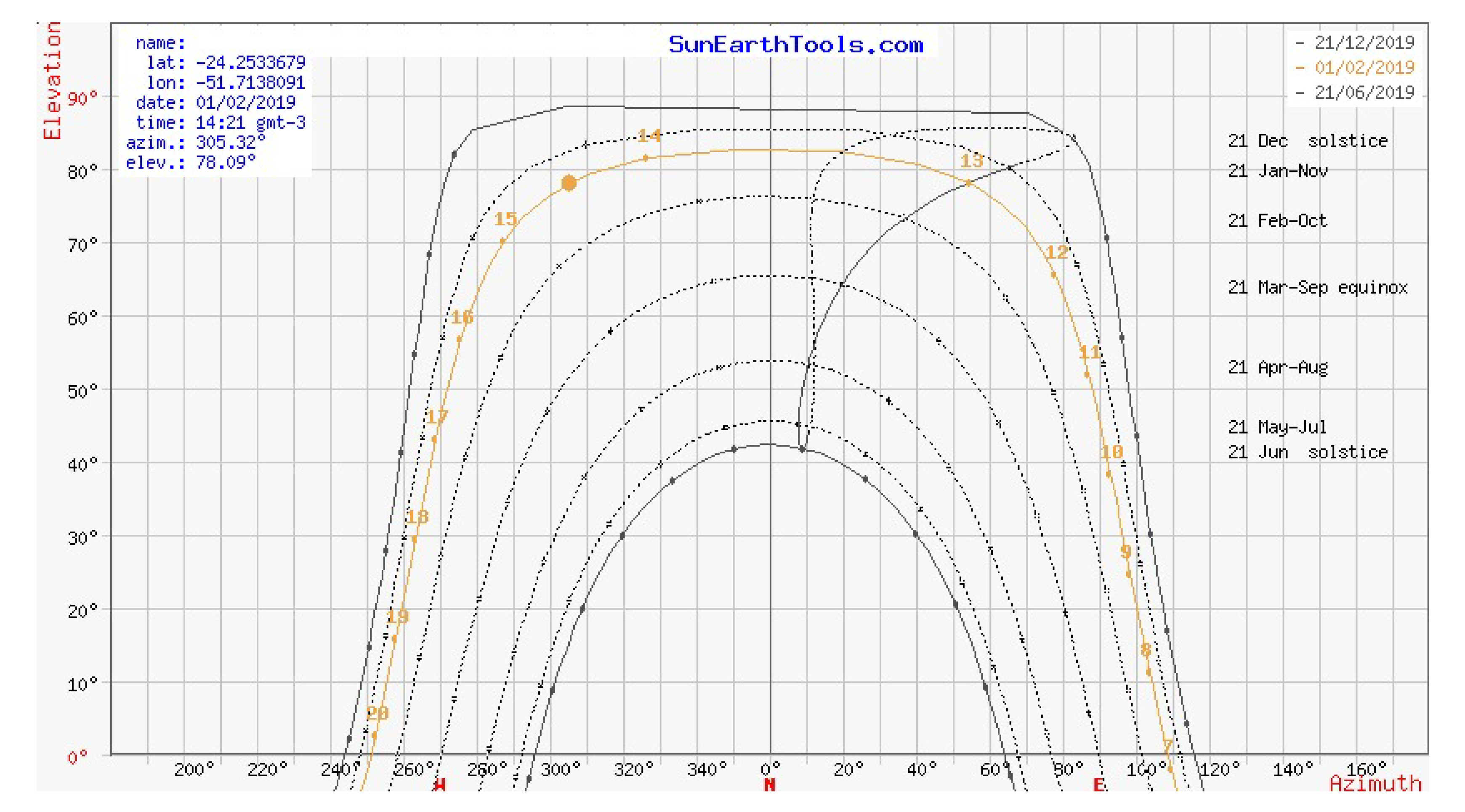
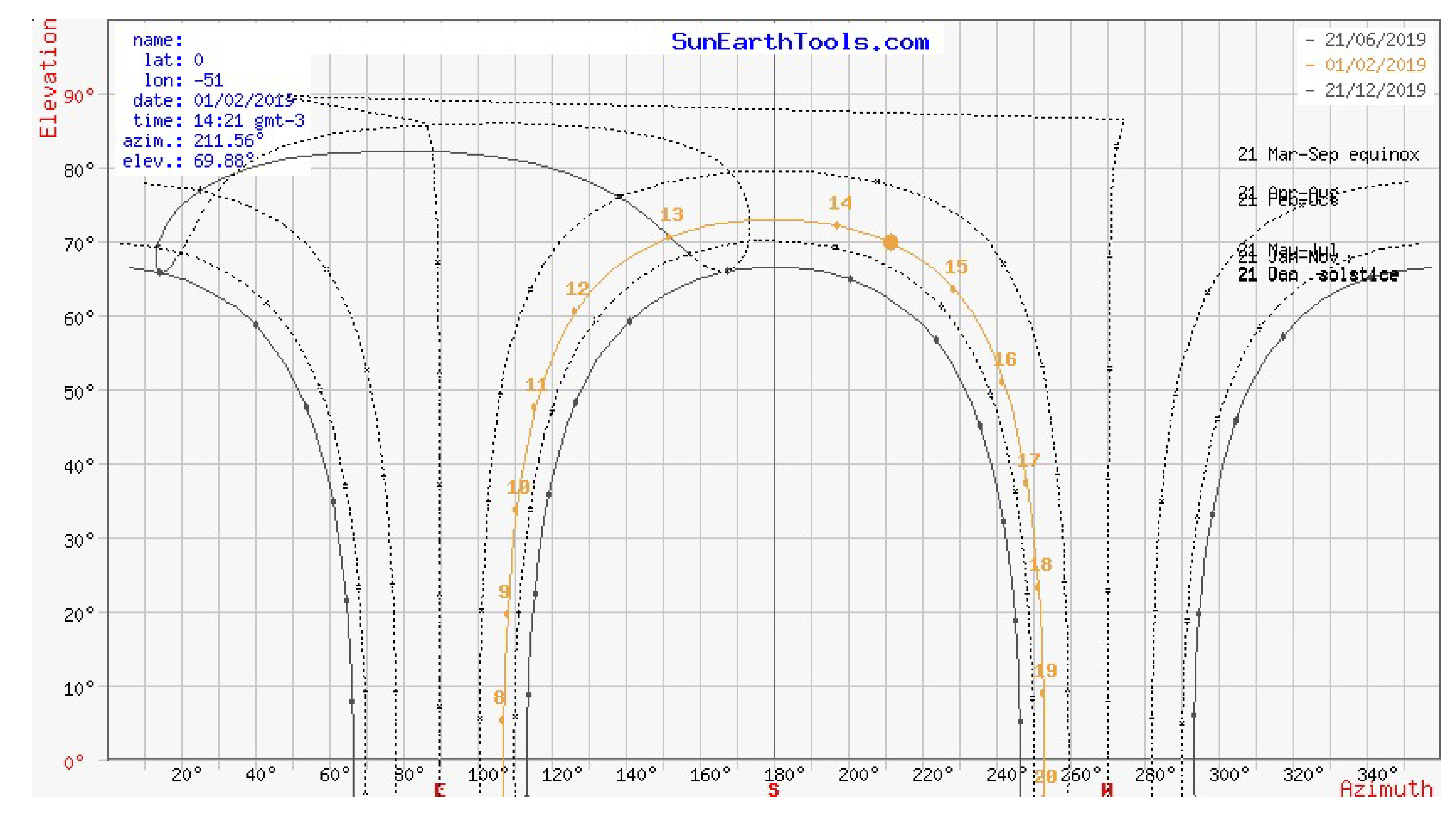
In this context, this paper aims to report the process of construction and automation of a two-axis micro-controlled solar tracker with a sensor tracking strategy. The electronics are based on an Arduino MEGA2560 and four LDR-type light sensors. The built prototype was able to track the Sun and position the solar panel with a tolerance of 1 degree, achieving 39.5% energy gain on a 13 summer-day period. The two-axis tracker was chosen due to the latitude where the prototype was installed (−24.25°).
Figure 1 shows the Sun’s apparent position and the annual variation at latitude −24.25°, and
Figure 2 presents this variation in a location with the same longitude but located on the equator line [
19]. In locations further away from the equator line, the variation in the elevation angle throughout the year is considerably greater, which justifies the use of a two-axis system due to its positioning capability, allowing us to keep the panel perpendicular to the Sun’s rays in every season.
The main contributions of this work are: to separate the structure of the tracker from the structure with the solar panel, allowing greater accuracy in tracking with lower power consumption due to the size and weight of the device; to use commercial solar panels with power of 275 Wp, simulating real applications; and to provide a proposal to change the tracking algorithm to consider periods of low irradiation, avoiding unnecessary device movement.
2. Prototype Construction
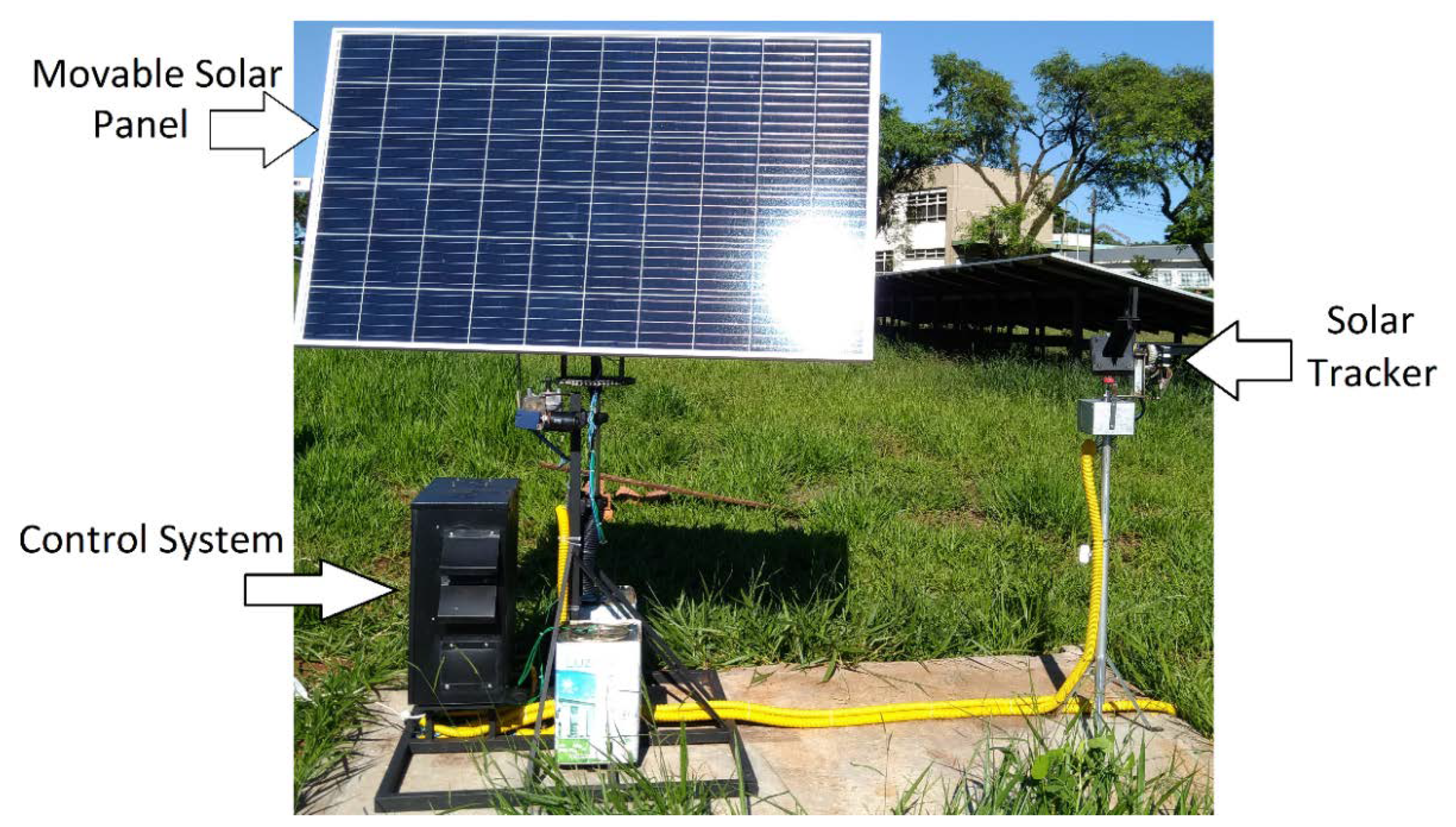
The proposed system (
Figure 3) consists of two mechanical structures with two axes of freedom, which are able to rotate around the elevation (angle to the horizon) and azimuth (angle to the north) axes, and one fixed structure with a conventional photovoltaic system. The first structure is equipped with two stepper motors and four light sensors, being responsible for tracking the apparent position of the Sun. The second structure uses direct current motors to move the photovoltaic panel.
Control and automation are centralized in a microcontroller electronic system, which performs analog sensor readings, communicate with digital sensors, run the tracking and positioning algorithms, in addition to controlling actuators.
The solar tracker device is constructed in an aluminum frame, with height adjustable by screw on a tripod, equipped with two stepper motors that provide movement in the angles of elevation and azimuth. These stepper motors are connected to the rotation system by endless screw, which amplify movement accuracy, enabling four steps per degree. In addition, the endless screw system allows motion transmission only in the direction of the frame, reducing external wind and gravity action. The light sensor array is positioned at the top of the device, consisting of a 20 cm high and 6 cm wide polyvinyl chloride cross structure and 4 light-dependent sensors.
Figure 4 shows the tracking device, with details for the endless screw system.
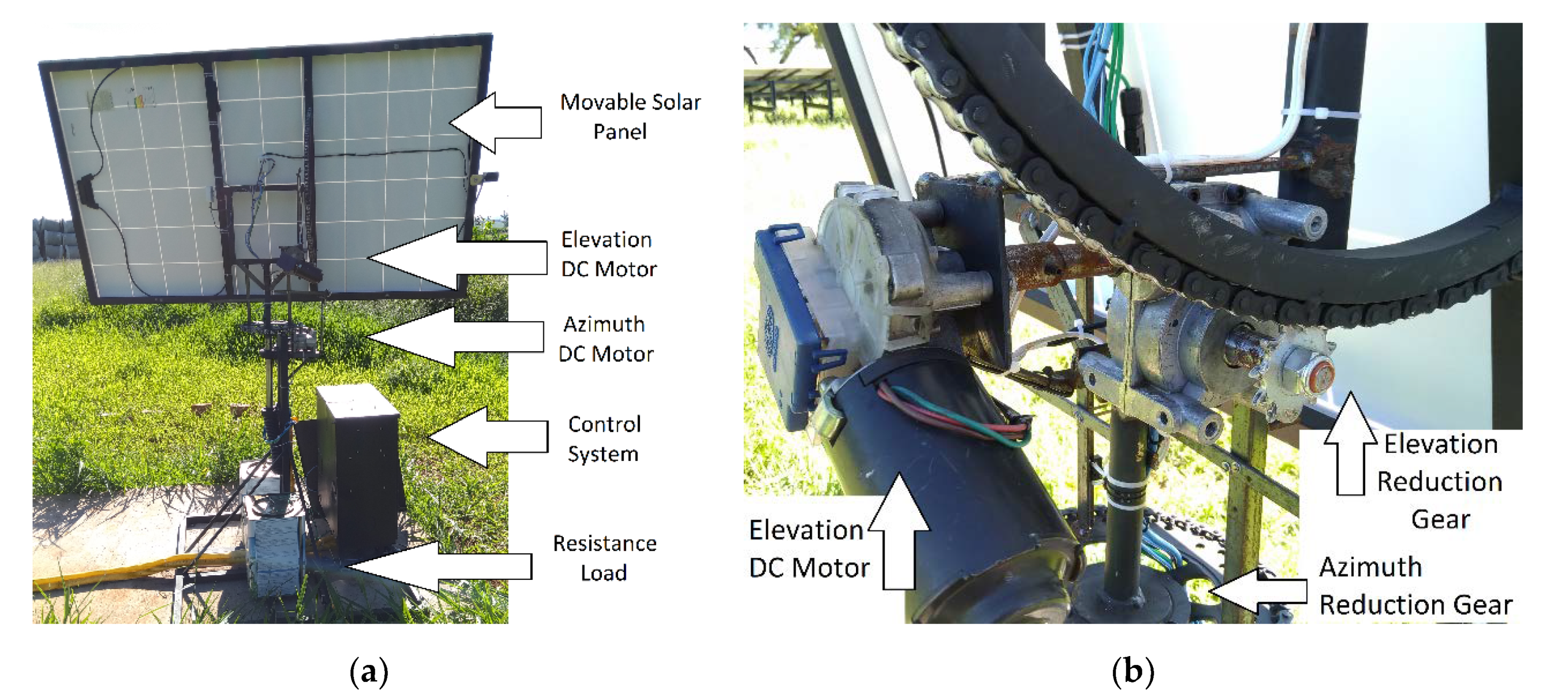
A steel structure with a fixed chain system coupled to DC motors was built to support the movable solar panel with dimensions of 1.5 m by 1 m and 18 kg, as shown in
Figure 5. Azimuth movement is achieved by means of a bearing connected to a disc, in which a chain was attached to the output of a 37:1 relation gearbox. For the elevation axis, the chain was welded in a metal semicircle, to which the same gearbox system is connected. This chain and gearbox system allows for greater movement accuracy and limits wind and gravity action, but the speed is reduced.
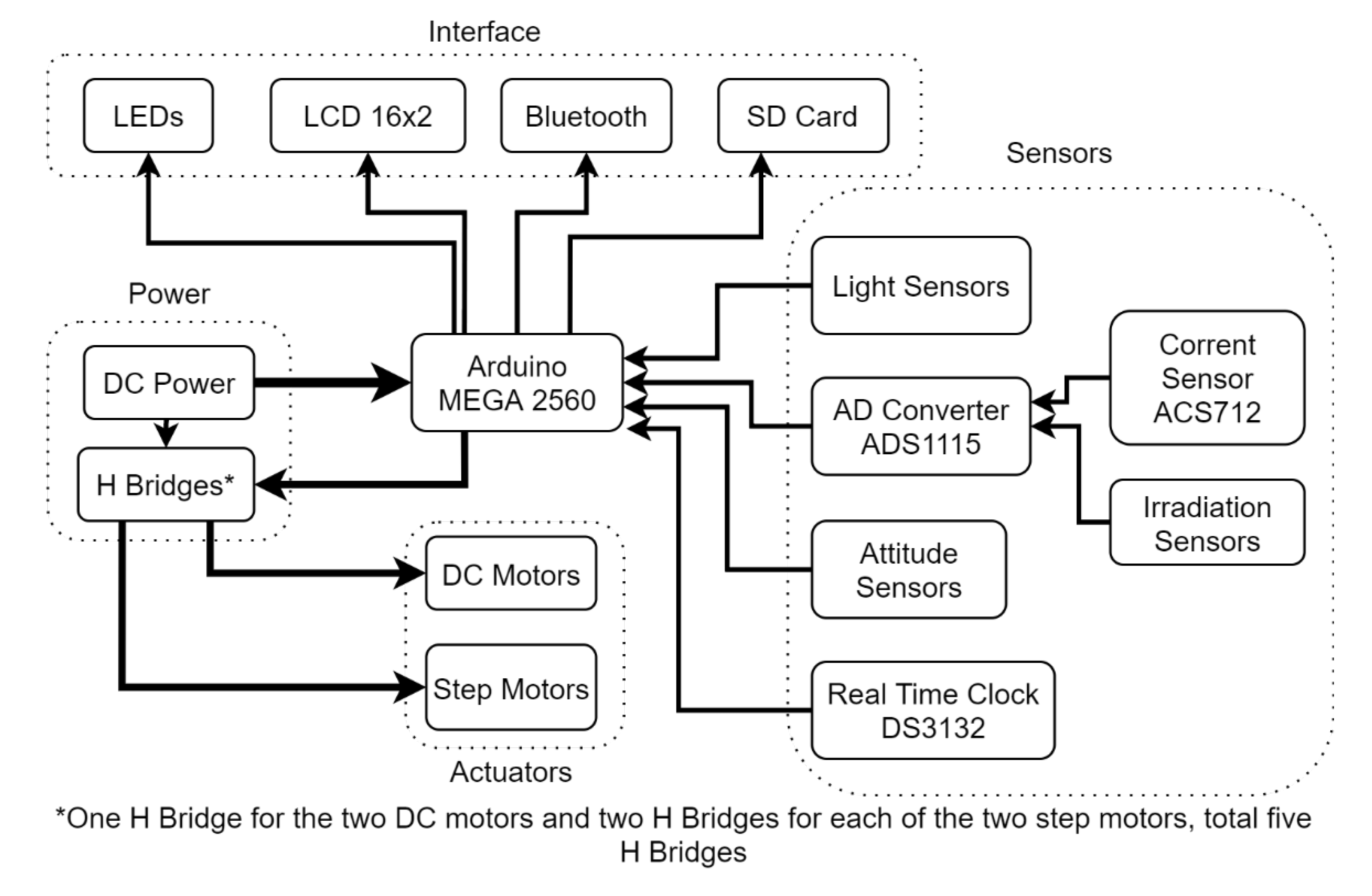
The electronics can be divided into five main modules, as shown in
Figure 6. Control and processing are centralized on an Arduino MEGA2560, whose purpose is to communicate with the other blocks through analog, digital signals and communication protocols. The human machine interface module contains status indicator LEDs, a 16 × 2 LCD display that shows the measured and calculated quantities, a Bluetooth wireless communicator for laptop connection and a SD storage card. The sensing module include the luminosity sensors (LDR), current sensor ACS712 and a Spektron solar radiation sensor connected to an analog-to-digital integrated circuit ADS1115 with 16 bits resolution, potentiometers serving as an angle sensor and a DS3132 digital watch. Finally, the power module consists of a DC voltage source with a rated voltage of 12 V and a maximum current of 10 A, together with the stepping motors and DC motors in the full bridge inverter configuration.
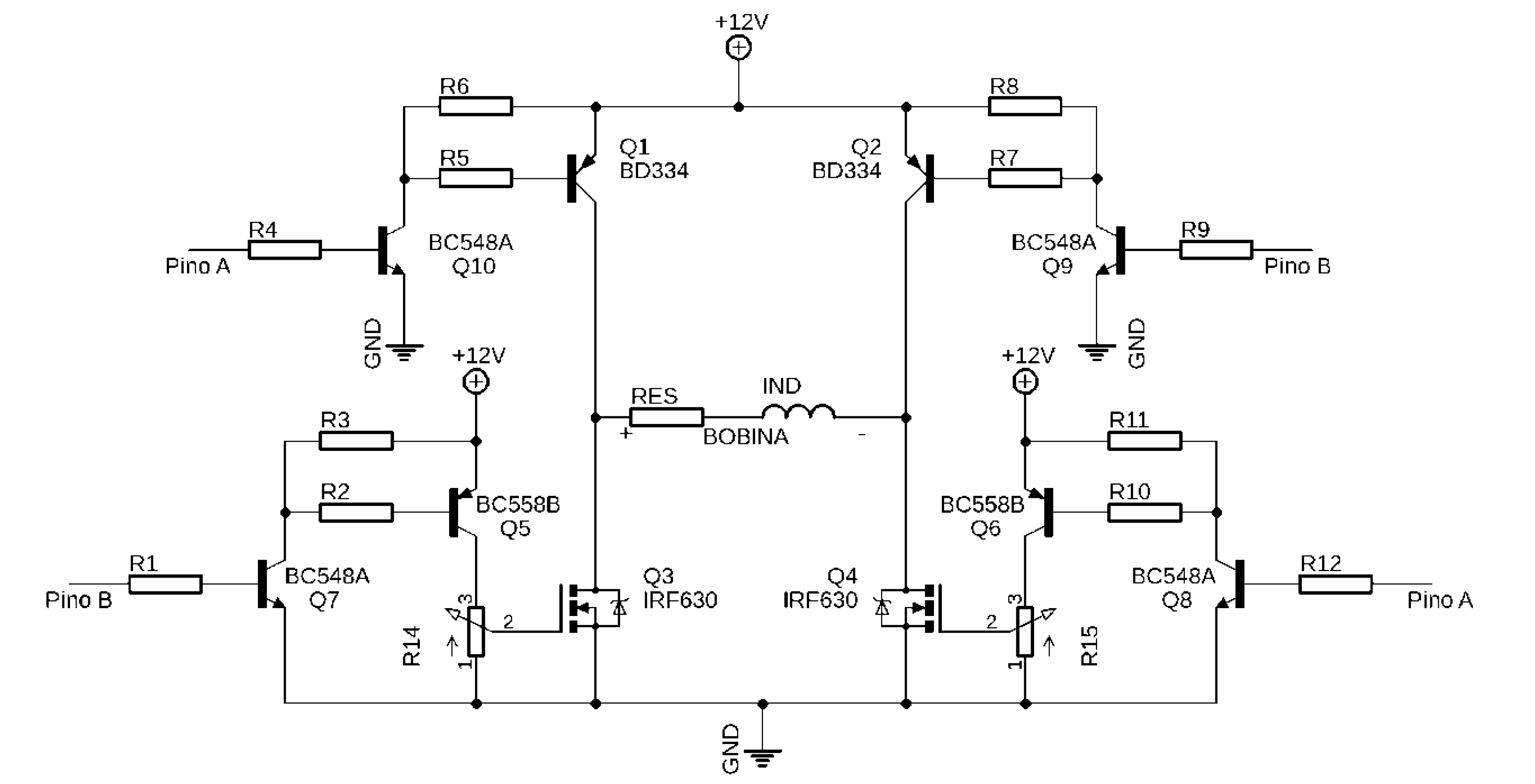
Due to the sequential drive characteristic of stepper motors, it was necessary to design a full bridge inverter circuit (
Figure 7) that offered the possibility of controlling the current at the output by means of an analog component, in contrast to the traditional method of pulse width modulation (PWM). For this purpose, potentiometers were connected to the gate of the power transistors on the low side of the bridge, since they are field effect and the drain-source current is proportional to the voltage at the gate. In this way, adjusting the voltage divider in the potentiometers, the output current was adjusted to 2.5 A, in order to reduce energy consumption and prevent damage to motors and transistors. There were five full bridge inverters, two for each bipolar stepper motor, and an additional one to control the DC motors.
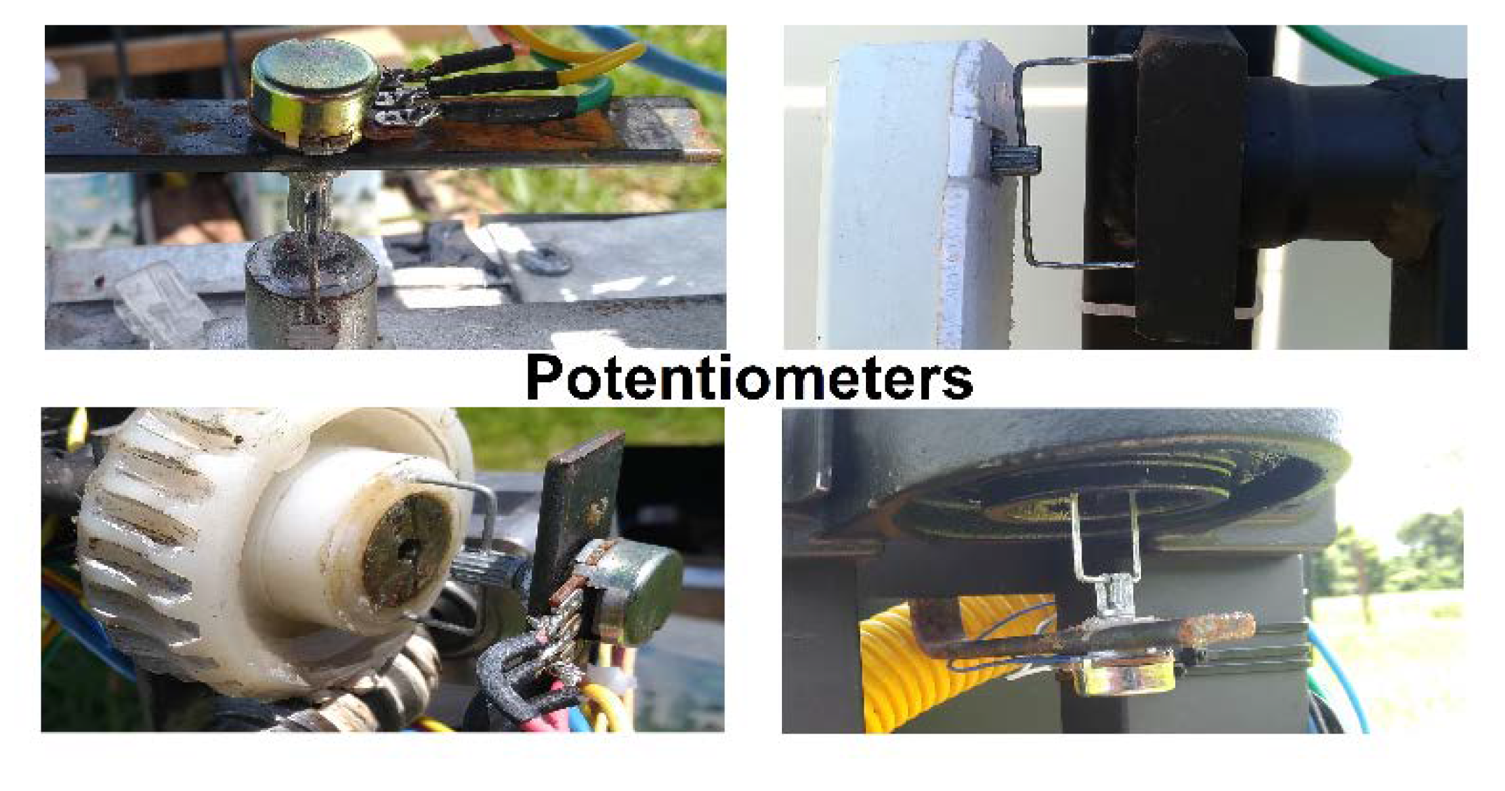
The sensing of the angular position of the two built structures was carried out by means of the analog reading of the central pin of linear rotational potentiometers with a total resistance of 1 kΩ. The relationship between the voltage read by the Arduino and the corresponding angle was performed in an experimental way, taking measurements at 5° increment. This dataset was used to adjust a cubic curve, which, together with moving average filters, perform the transformation of the read value in the AD to angle.
Figure 8 shows the potentiometers used in the two structures.
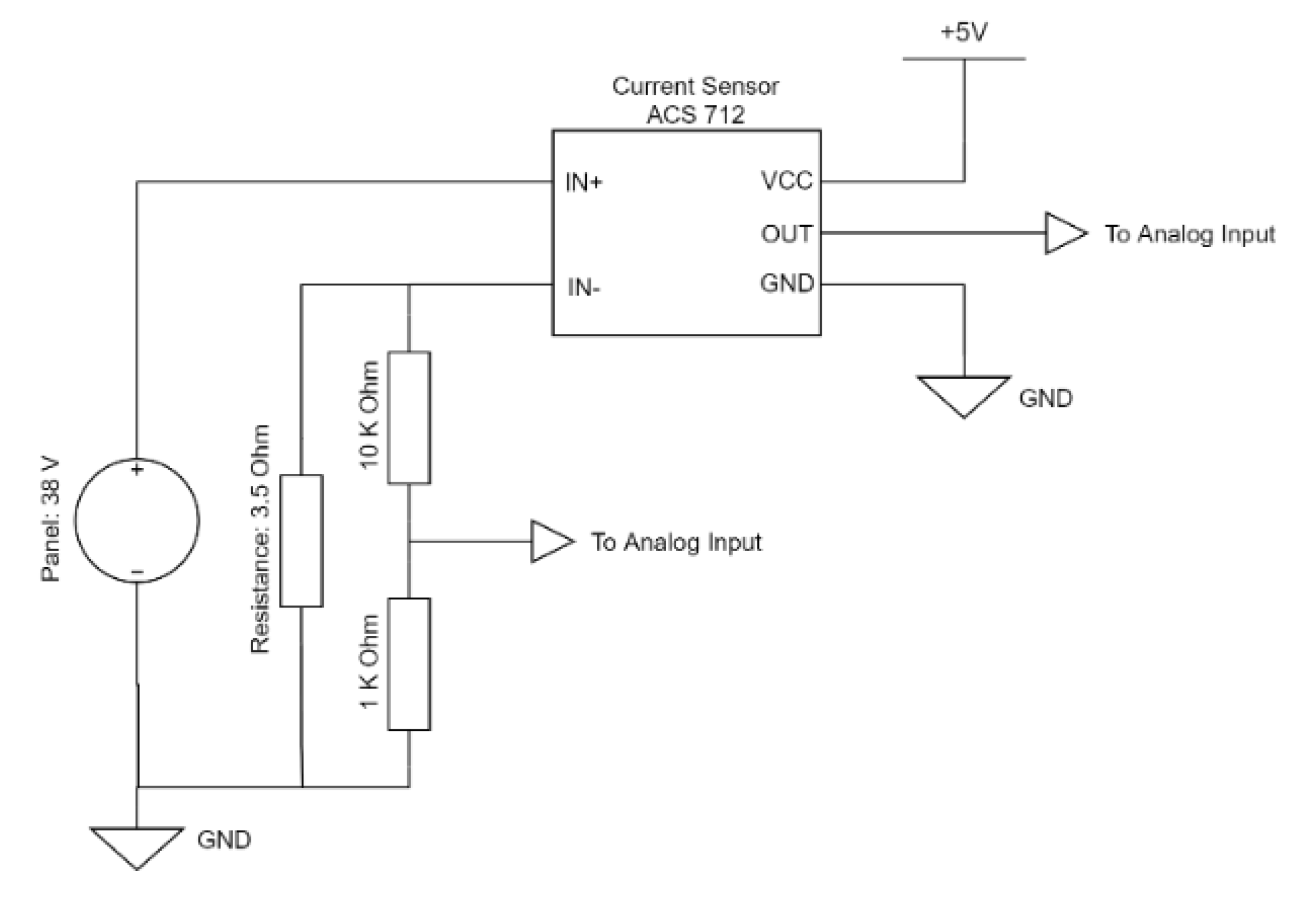
The used solar panels characteristics are 38 V, 8 A and 275 W peak. To dissipate the generated power, shielded resistances of 3.5 Ω were used in an aqueous bath. The voltage is monitored by means of a voltage divider circuit with an attenuation factor of 1 to 11, connected directly to the Arduino AD converter (
Figure 9). The current is measured by and ACS712 Hall Effect sensor, whose output is connected to the ADS1115 AD converter, in order to increase measurement accuracy. The Arduino, through the direct multiplication of the voltage by the current, calculates the generated power in each panel.
A cup anemometer was used to measure wind speed, in order to interrupt the system’s operation when wind speed exceeds 13.9 m/s, positioning the panel parallel to the ground, to avoid damage risk to the prototype. The DS3132 digital clock was used in combination with the SD memory card to store the main quantities measured and calculated in an orderly manner. The electronic system was installed inside a recycled electrical panel, in which two cooling fans were installed.
3. System Automation
System automation was developed in the official Arduino integrated development environment in processing language, which is based on C/C++. Fundamentally, the program consists of algorithms for tracking the Sun’s apparent position and for controlling the photovoltaic panel position. The first algorithm aims to find the relative position of the Sun in the form of the azimuth and elevation angles, using the stepper motors’ ordered movement on the tracker structure. The angle values found are used as input reference for the second algorithm, which drives direct current motors to control the solar panel angular position.
Figure 10 shows the block diagram of the closed loop control system.
The Sun tracking method employed is based on using four light sensors in a cross structure. The sensors are light-dependent resistors (LDR) whose resistance drops dramatically with the incidence of light (from MΩ to a few hundred Ω). Each LDR is connected to a voltage divider circuit together with a resistor, so the light intensity can be measured indirectly through the analog to digital converter. When the cross structure is aligned with the Sun’s rays, the four sensors are illuminated equally, resulting in very close voltage readings. When misalignment occurs, LDRs receive light unevenly, causing an imbalance in sensors readings.
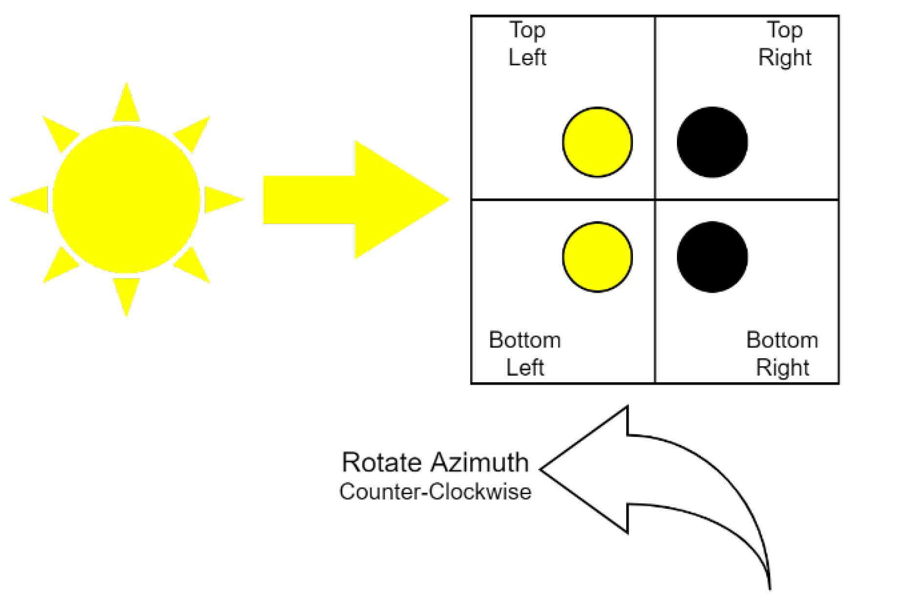
Figure 11 illustrates the Sun’s rays striking unevenly between the left and right sensors, causing a reading difference that indicates the direction of rotation in the azimuth angle. The same principle can be applied when there is an imbalance between the lower and upper sensors whose voltage difference points to the direction of rotation at the elevation angle.
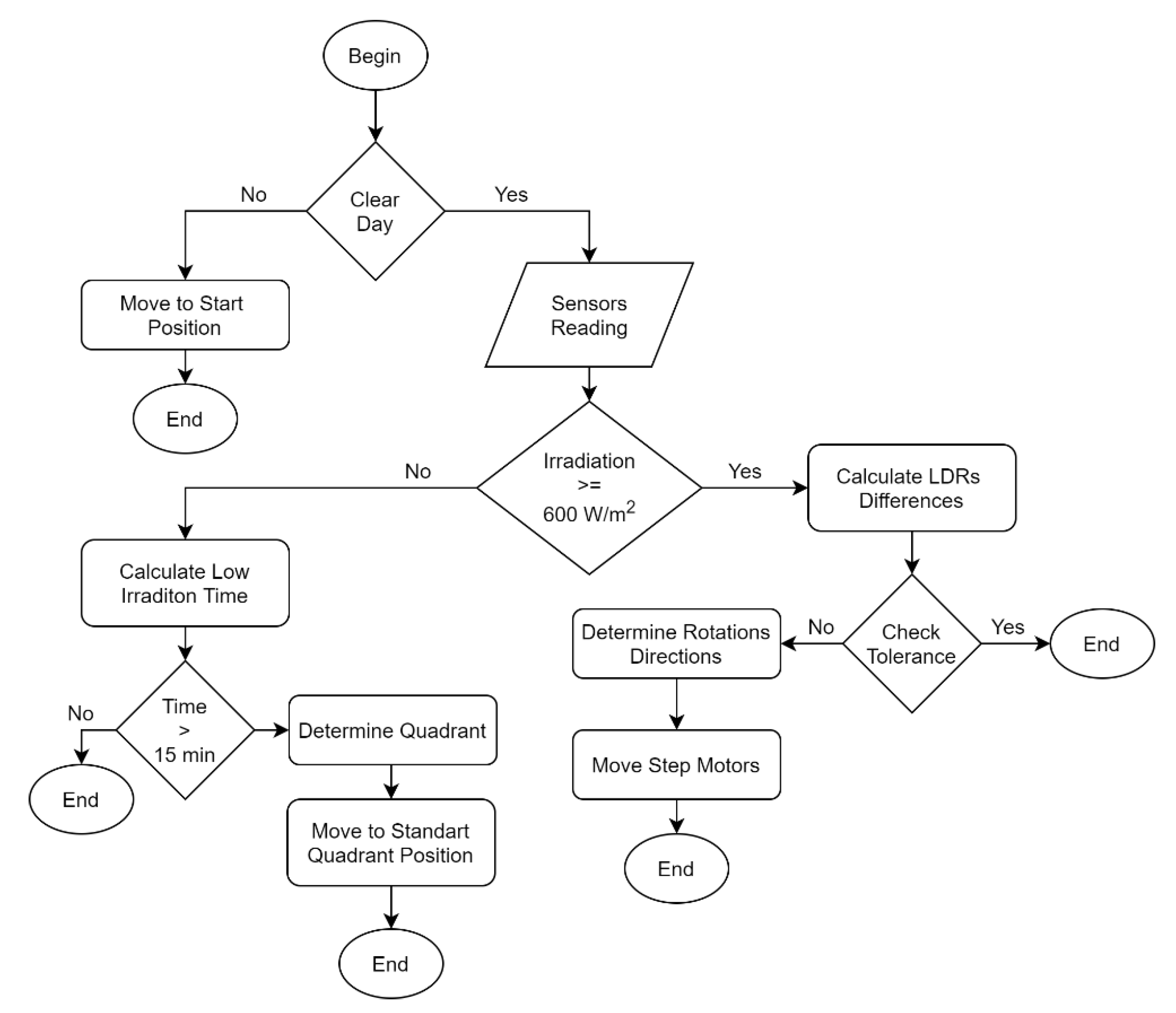
Figure 12 presents the flowchart of the sensor-tracking algorithm, divided into three situations: nightfall, daylight with irradiation lower than 600 W/m
2 and daylight with irradiation higher than 600 W/m
2. During nightfall, both the tracker and the movable panel structure moves towards the east in an initial position. The tracking strategy based on light sensors depends on high irradiation level; therefore, when the irradiation is below minimum, the tracker does not move, and if this situation lasts more than fifteen minutes, the movable panel structure moves towards a default position based on the current hour of the day. When irradiation levels exceed the minimum, the algorithm follows the proposed methodology, moving the step-motors based on the LDR reading difference. As soon as the LDR difference became within a tolerance, the tracking algorithm converge and output the elevation and azimuth angles as reference to the positioning algorithm.
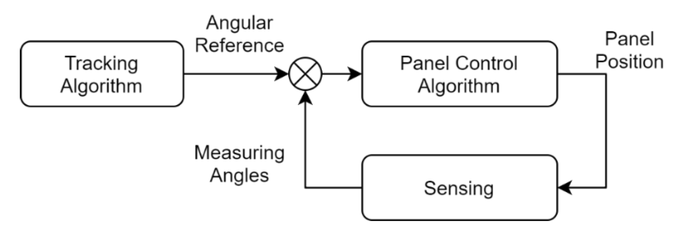
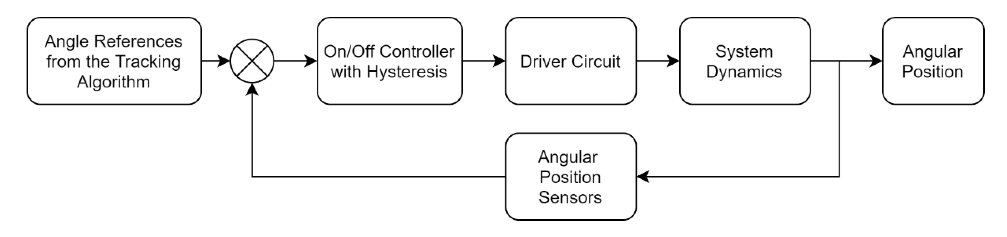
A simple closed loop on-off controller with hysteresis performs the movable solar panel angular position control, as shown in
Figure 13. The angular reference comes from the tracking algorithm and is used, together with sensing, to determine the error signal. This signal determines the full bridge inverter direction of activation to drive the two DC motors. In this type of controller, hysteresis allows a balance zone around the reference point, preventing unnecessary and continuous switching of the actuator.
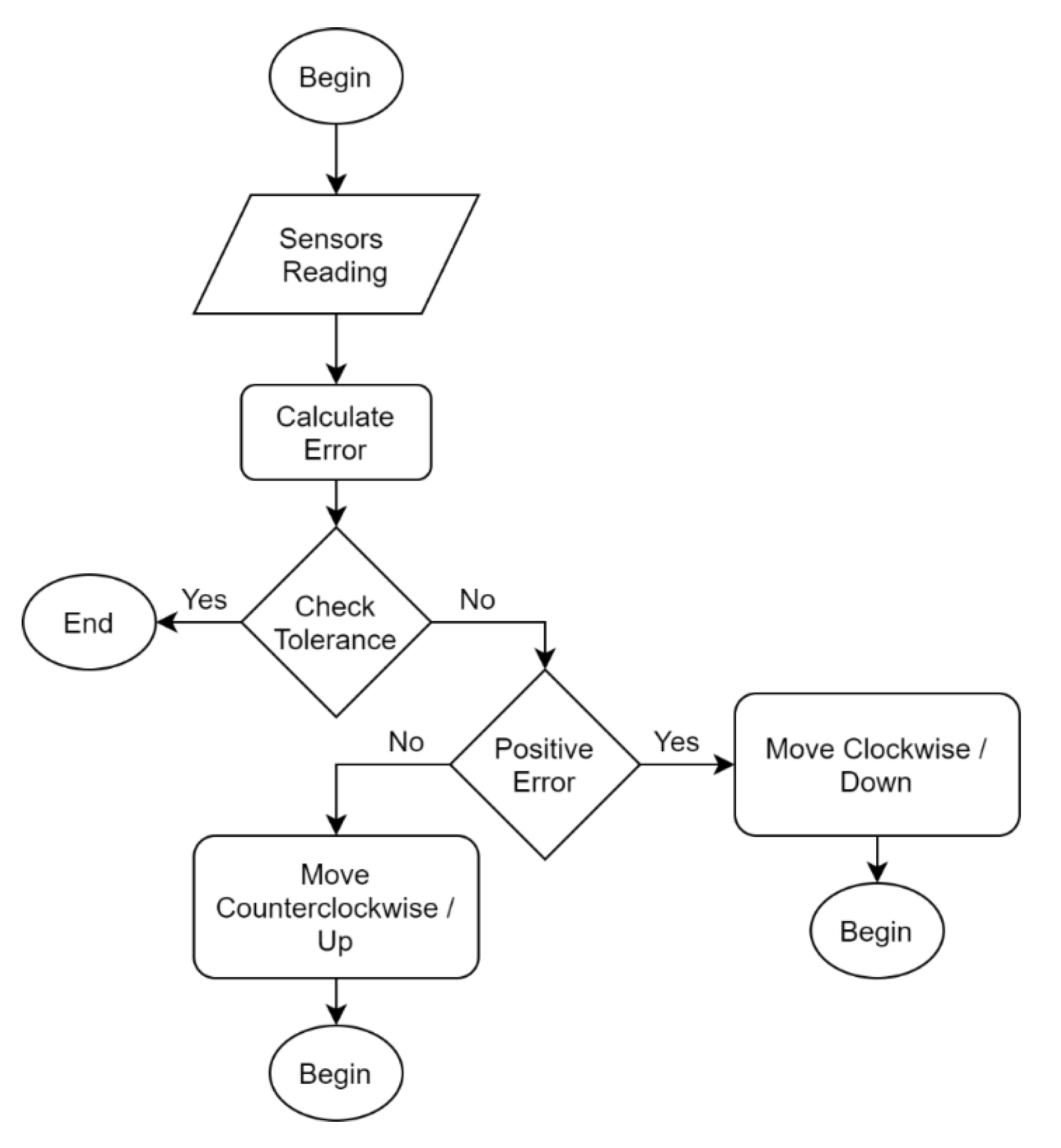
Figure 14 shows the solar panel control algorithm flowchart. The DC motor movement direction is determined by the calculated error. As soon as this error comes within a 1° hysteresis, the algorithm converges and the motors are turned off.
As only one drive circuit was used for the two DC motors, it was necessary to control the angles separately. Thus, the algorithm first controls the elevation angle until it converges and then controls the azimuth angle. It was installed with four switches, which prevents the passage of current to the motor in case of failures.
4. Results
The prototype construction was the most laborious and time-consuming stage of the project, requiring several cycles of conception, construction, tests and validations. The obtained result was satisfactory, since the tracking device presented smooth and precise movements, and the movable panel structure was able to support the weight of the solar panel. The electronic system performed its functions efficiently, despite employing simple and inexpensive materials.
To evaluate the response of the tracking algorithm, the transition from a period of dense clouds with low irradiation to open skies with high irradiation was recorded. Thus, the algorithm started with the Sun’s apparent position reference distant from the current angles of the tracking device.
Figure 15 shows the tracking algorithm response, with the elevation angle and reference in blue and the azimuth angle and reference in red. It can be observed that the variation in azimuth angle was approximately 50 degrees, leading to a convergence time of 220 s. For the elevation angle, the variation was 16 degrees, with a convergence time of 158 s. Although long, the convergence times are compatible with solar movement, which is approximately 15 degrees per hour. It is important to note that the two angles are actuated simultaneously, seeking the apparent position of the Sun.
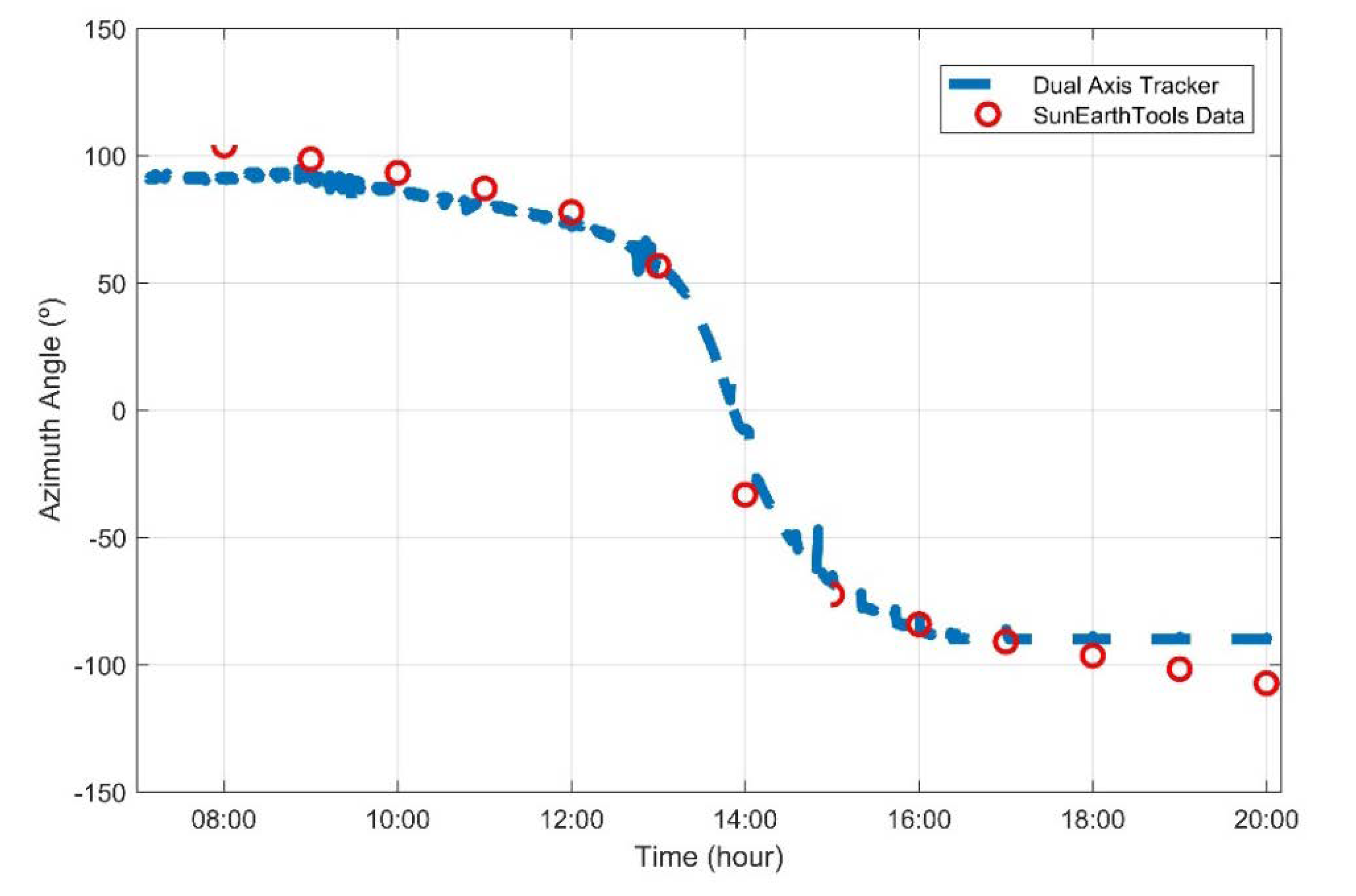
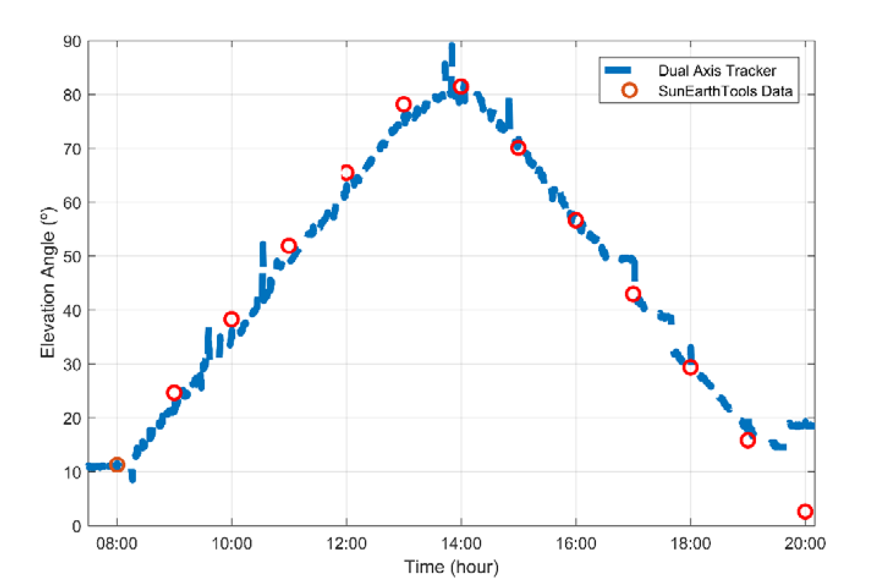
Figure 16 and
Figure 17 illustrate the behavior of the tracker’s elevation and azimuth angle (in blue) compared to SunEarthTools database (in red) in February 1st (summer) [
19]. In the first half of the day, the tracker presents a small difference from the values provided by the database, in contrast to the second half, where the values almost overlap. Relative to the elevation angle, the tracker presents some peaks due to the tracking algorithm, as well as two inoperative moments (between 16 h 30 min and 18 h) due to the presence of clouds and operates from 10° to 90°. The tracker azimuth angle is mechanically restricted to operate from −108° to 108°.
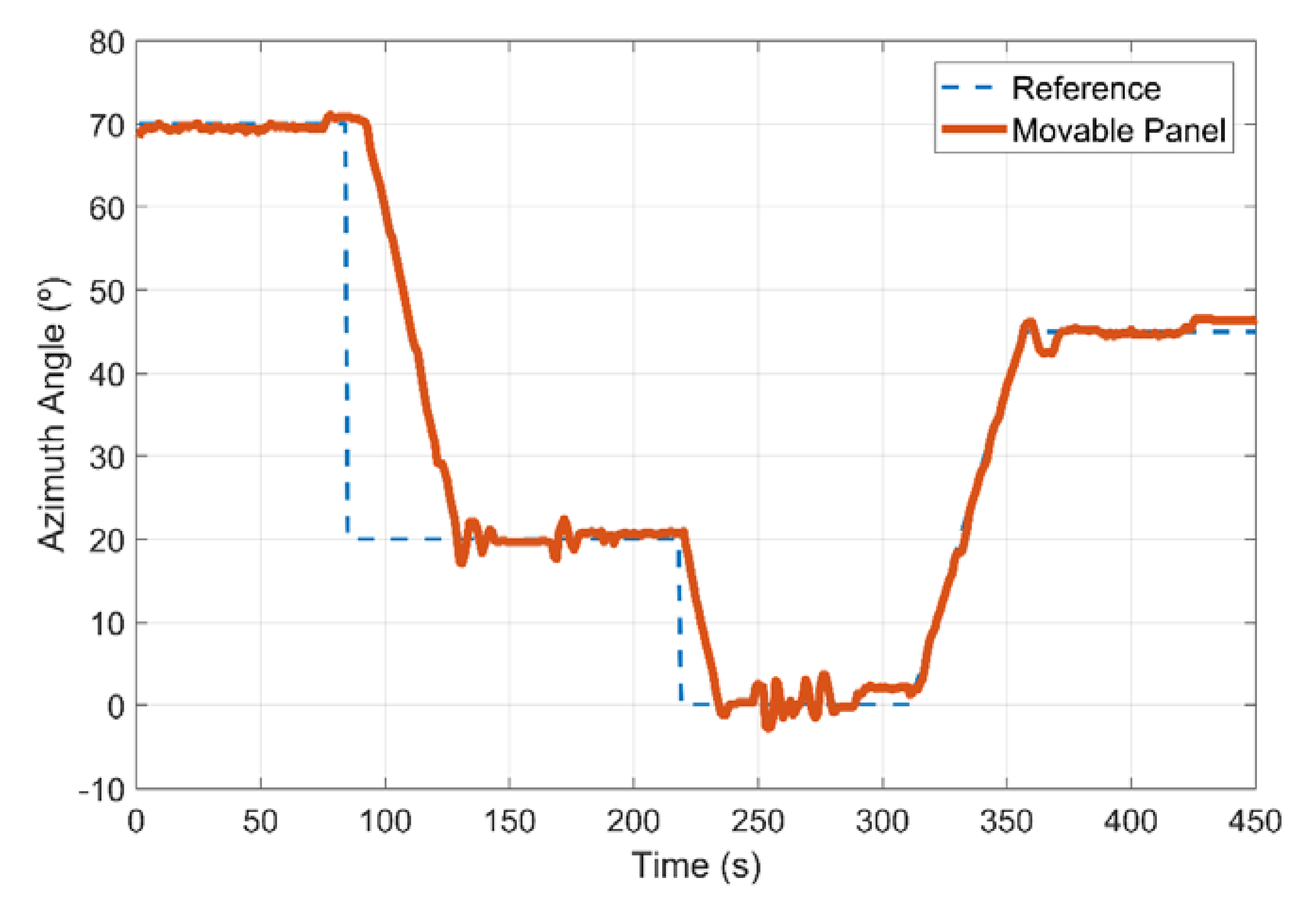
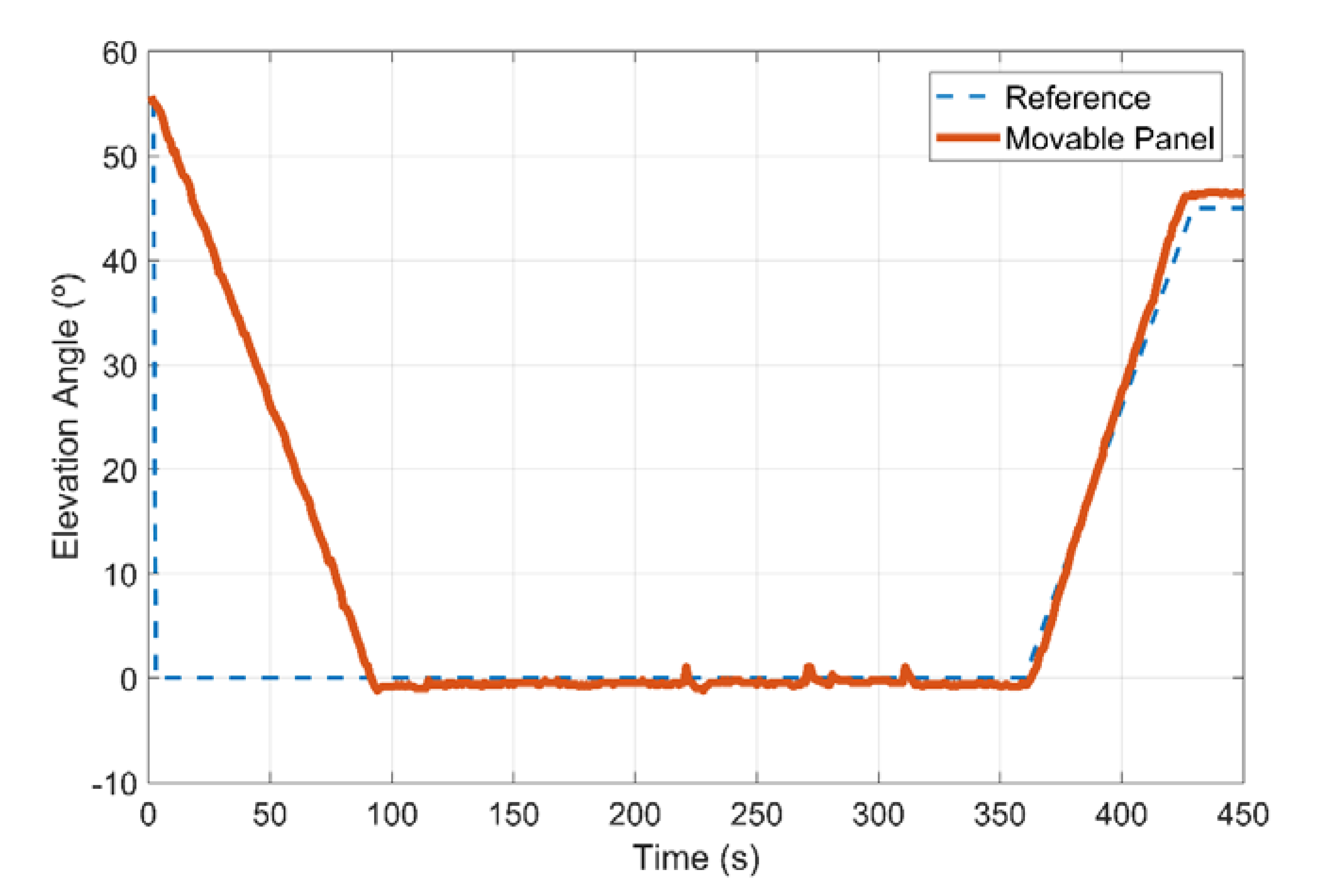
To evaluate the movable panel position control, a step and a ramp were inserted at the reference.
Figure 18 shows the azimuth angle response, with a step from 70 to 20 degrees, followed by another step from 20 to 0 degrees, and a ramp from 0 to 45 degrees at a rate of 1 degree per second. The DC motor speed is slow due to the reduction gearbox, making the step response slow. Regarding stability, the on-off control system features overshoot, associated with wind incidence and a small gear backlash. For the angle of elevation (
Figure 19), the overshoot is smaller because the mechanical system is heavier and better fitted, so that the influence of wind is smaller.
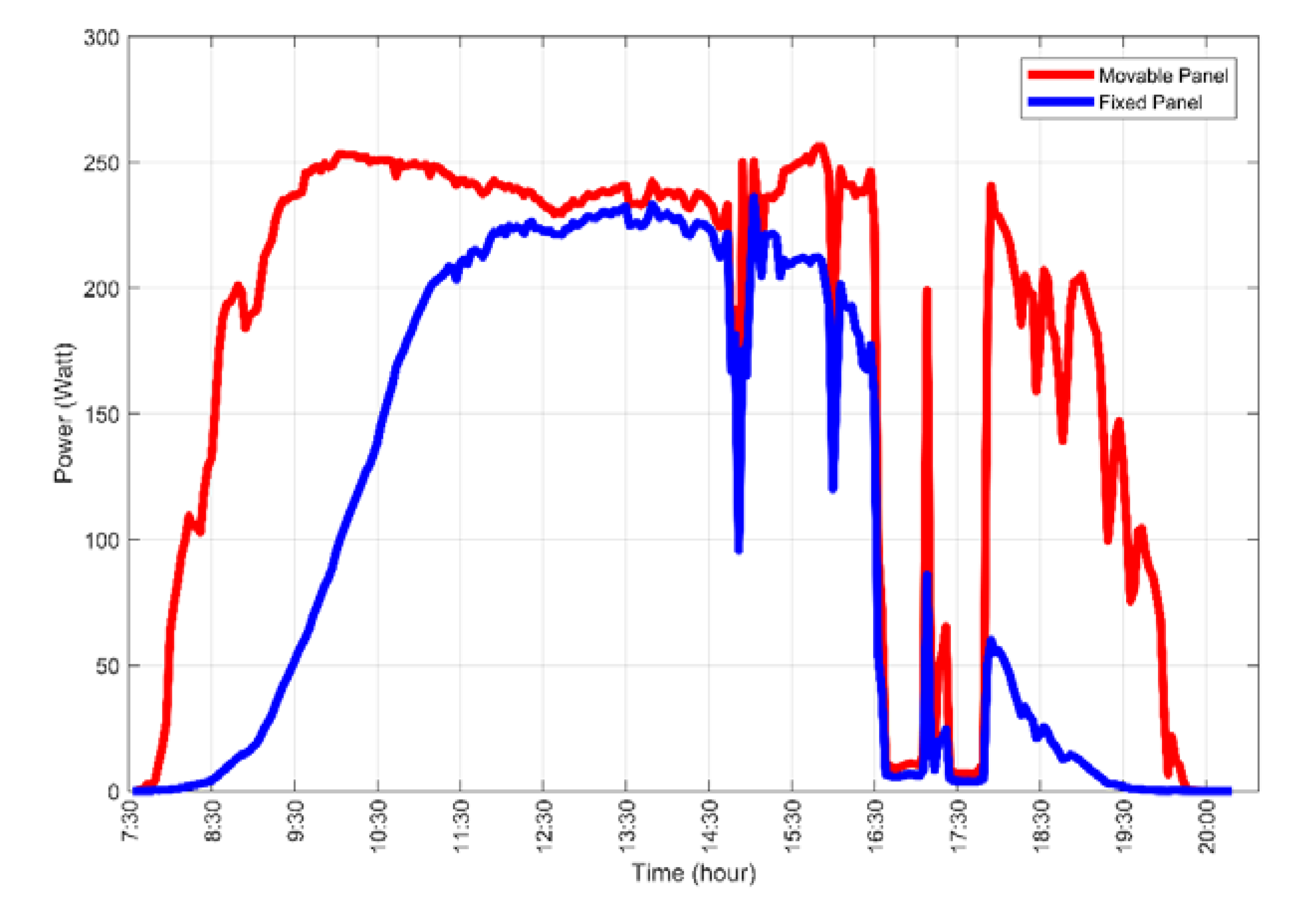
In order to observe the full functioning of the system, the power supplied by the fixed panel and the movable panel was recorded in a SD memory card, as well as the power supplied by the direct voltage source, with one input per second from 7:00 a.m. to 9:00 p.m. on a 13 summer-day period in the city of Ivaiporã-Paraná. Mathematical computing software was used to perform numerical integration on power data and determine the energy generated per panel and provided by the source to the tracking system.
Figure 20 shows the power generated by the fixed panel in blue and by the movable panel in red on February 1st. It can be seen that the movable panel has an expressive power output at 8:00 a.m. reaching a maximum at 9:30 a.m., while the fixed panel starts to have a significant power only at 8:30 a.m. and reaches its maximum value at noon. In this period of about four hours, the power observed in the tracking system exceeds the power of conventional fixed systems. This phenomenon repeats at 3:30 p.m., but it is interrupted due to the presence of clouds between 4:30 p.m. and 5:30 p.m. In total, the fixed photovoltaic system generated 1300 Wh, while the solar tracking system generated 2115 Wh, indicating a total energy gain of 815 Wh on this day, equivalent to 62.58%. To power the tracking and positioning system, the direct voltage source provided 76.93 Wh, causing the net energy gain to fall to 737 Wh, or 56.67%.
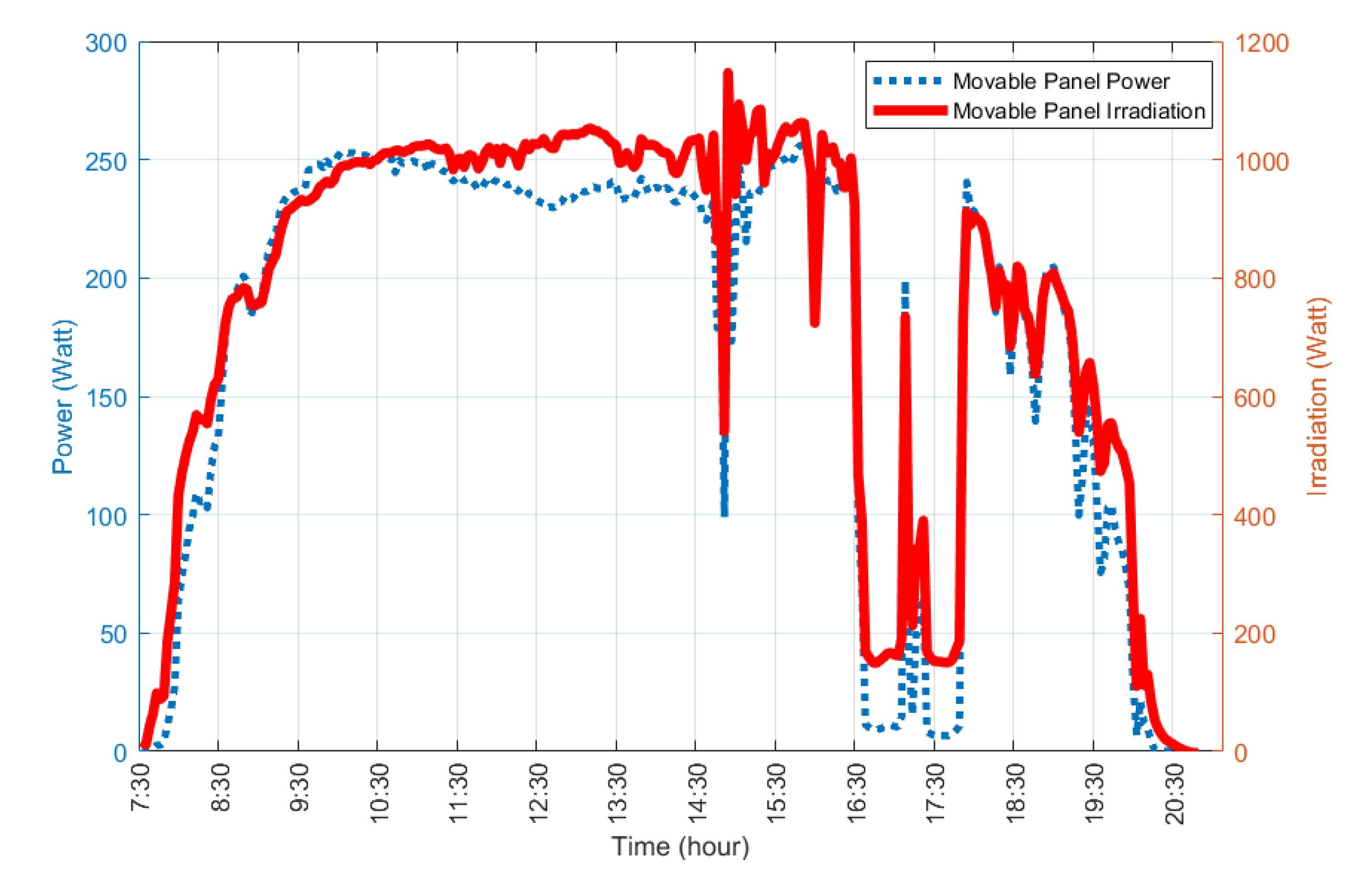
Figure 21 shows the relation between the irradiation and power generated by the movable panel in the same day. The two curves follow the same pattern, with peaks and lows at the same time, except for the central period in which the high temperature affects the panel efficiency. The total irradiation received on this day was 13,712 Wh, leading to 15.42% panel efficiency.
The system operated from February 1st to 16th, in which three days’ worth of data were corrupted (11th to 13th), six days were sunny (1st, 6th to 9th and 14th), six days were cloudy (2nd to 5th, 10th and 16th) and one day had heavy rain (15th).
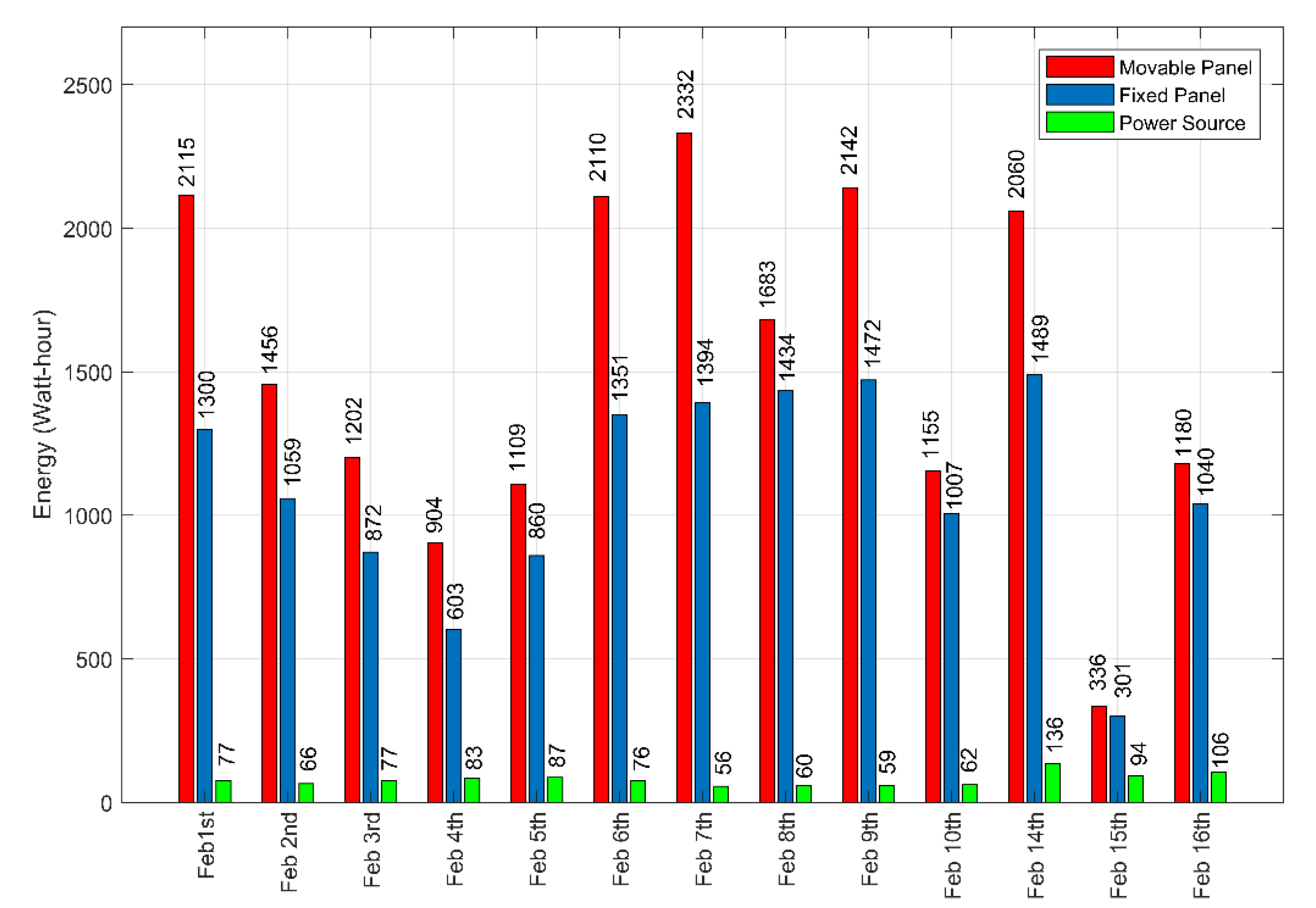
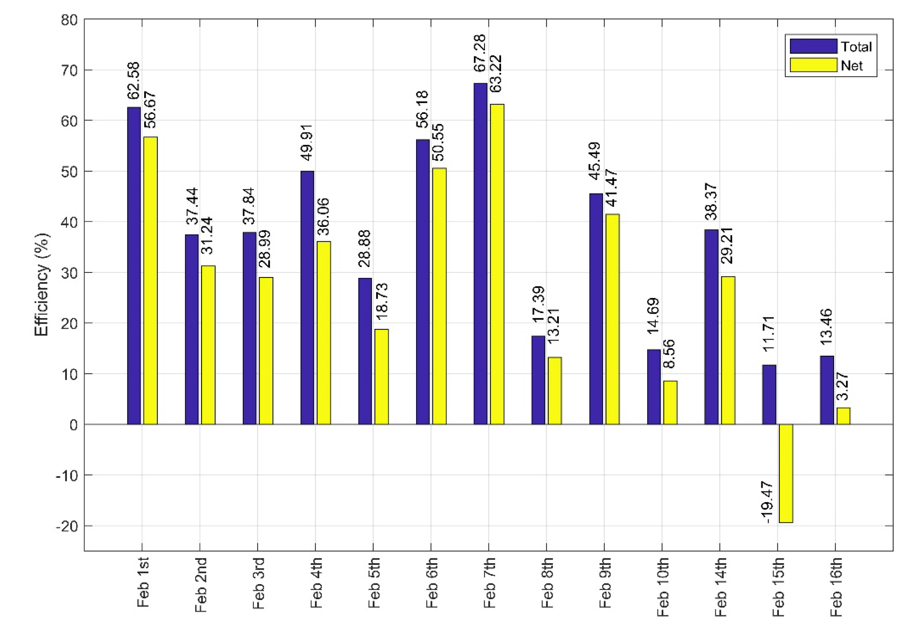
Figure 22 shows an energy comparison between the movable panel, fixed panel and the power source. February 7th is an example of a sunny day, wherein the movable panel generated 2332 Wh, the fixed panel generated 1394 Wh and the power source consumed 56 Wh, resulting in a total gain of 67.28% and net gain of 63.22%. For cloudy days, the systems total and mostly the net efficiency drops—ion February 3rd, the movable panel generated 1202 Wh, the fixed panel generated 872 Wh and the power source consumed 77.18 Wh, resulting in a total gain of 37.84% and net gain of 28.99%. The worst possible climate condition is heavy rain with small periods of high irradiation, like February 15th. On this day, the movable panel generated 336 Wh, the fixed panel generated 301 Wh and the power source consumed 94 Wh, resulting in a total gain of 11.71% and net gain of −19.47%. During the experimental period, the movable panel generated 19,784 Wh, the fixed panel generated 14,182 Wh and the power source consumed 4562 Wh, leading to a total gain of 39.5% and net gain of 32.16%. It is worth noting that the movable panel generated more power than the fixed panel on every analyzed day. In regard to the system efficiency,
Figure 23 summarizes the obtained values for the total and net gains, which have a strong relationship with the incidence of clouds and rain.
5. Conclusions
In this work, we report the process of the construction and automation of a two-axis microcontrolled solar tracker, in which the tracking process is performed in a separate structure, equipped with stepper motors with precision of four steps per degree, applied to a photovoltaic system with commercial panels of 275 Wp. The mechanical structures manufactured were satisfactory, meeting the requirements of movement precision, load capacity and resistance. Although simple and inexpensive, the electronic system performed its function efficiently. In general, the developed prototype is applicable in studying tracking strategies and the control of DC motors, with potential to become a commercial product if the number of controlled panels is increased.
The tracking algorithm used was able to find and follow the apparent position of the Sun in periods of high irradiation, with a proposal to handle exceptions for low irradiation intervals that seek or avoid unnecessary movements in the tracker. The on–off controller with hysteresis achieved its goal of positioning the moving panel on the reference obtained by the first algorithm. However, due to the overshoot presented in its answer, it is believed that this controller is not the most suitable for solar tracking systems, since some of the energy spent in moving the motors is wasted.
An evaluation of the system efficiency was performed, comparing the energy generated in the mobile panel with that of a fixed panel on a 13 summer days period, taking into account days with high incidence of irradiation, cloudy and rainy days. The system total efficiency was 39.5% and the net efficiency was 32.16%, considering the energy used to operate the system in the same period. For future research, it is suggested to evaluate the prototype performance with tracking strategy based on astronomical equations, as well as to apply controllers that minimize energy consumption in the positioning of the moving panel.

 ,
, 


