Article

Chaotic Mixing Analyzing in Continuous Mixer with Tracing the Morphology Development of a Polymeric Drop

1
School of Physics and Astronomy, Yunnan University, Kunming 650091, China
2
International Joint Research Center for Optoelectronic and Energy Materials, School of Materials and Energy, Yunnan University, Kunming 650091, China
3
Engineering Center of Efficient Green Process Equipment and Energy Conservation, Ministry of Education, East China University of Science and Technology, Shanghai 200237, China
*
Authors to whom correspondence should be addressed.
Processes 2020, 8(10), 1308; https://doi.org/10.3390/pr8101308
Submission received: 15 September 2020 / Revised: 9 October 2020 / Accepted: 14 October 2020 / Published: 18 October 2020
(This article belongs to the Section Materials Processes)

Abstract

:
The chaotic mixing process in a continuous mixer plays an important role and has an essential influence on the performance of prepared materials. To reveal how a polymeric drop experienced the chaotic mixing and give more specific analysis about the chaotic mixing, the morphology development of a single drop was traced and recorded with an on-line visualization system. The drop would undergo elongation deformation, reorientation, and folding process, which were the typical signs of chaotic mixing. The elongation deformation was an important precondition for drop experiencing the reorientation and folding process and mainly existed in the region near the barrier, rotor tip clearance, and wedgelike region. The reorientation and folding process mostly appeared in the region near the rotor flat and interaction window. Besides, the erosion process of the drop was observed at the initial stage under lower rotor rotation speed. The chaotic mixing always held the dominant place in continuous mixer although the rotor rotation speed and drop viscoelasticity were adjusted. In this work, the chaotic mixing in a continuous mixer was dynamically presented. The dynamical results would give a more real and visual understanding of the chaotic mixing.

1. Introduction

In the polymer processing industry, the mixing process in mixer or extruder was a key factor determining the performance of the prepared material [1]. The mixing process showed many interesting behaviors related to the morphology development of the disperse phase, which resulted from the flow field in the mixer or extruder [2,3]. Thus, the morphology development would give some indication about the flow characters in the mixing process. The experiment basing on the visualization technology was an effective method for observing the morphology development and understanding the mixing process [4]. However, the mixing process in mixer or extruder was relatively complicated, which was originated from the complex configuration of the mixing chamber and mixing element. Therefore, it is difficult to realize the on-line observing the morphology development of the disperse phase in mixer or extruder [5].
Considering the shear flow was in the dominant place for mixer or extruder, Bin Lin et al. [6,7,8] visualized the morphology development of polycarbonate (PC) drop in polyethylene (PE) matrix with a Couette device or parallel plate setup, and revealed the disperse mechanism of single PC drop in simple shear flow. The results indicated that PC drop immersed in PE matrix would experience the erosion, elongation, and breakup process in simple shear flow. Frej Mighri and Michel Huneault [9] observed the polystyrene (PS) drop morphology deformation in the PE matrix with a Couette device, and the erosion process of PS drop was observed together with the elongation, orientation, and breakup process. Although the visualization of polymer drop in simple shear flow would help understand the morphology development and disperse mechanism, it is not enough for presenting the real mixing process. Thus, despite the complication of the mixing process, visualization experiments were conducted to give more detailed information about the mixing process [2,10,11,12,13,14,15,16,17]. Bo Yin et al. [2] examined the PC drop morphology development along the screw axis with a scanning electron microscope in a twin screw extruder and proposed two models to describe the morphology development. The models indicated that the PC drop would mainly experience the elongation process, and then breakup when elongation deformation exceeded the limit. Hongbing Chen et al. [17] revealed that the PC drop would primarily go through the erosion process in a twin-screw extruder under the assistant of on-line observing the morphology development of PC drop.
The continuous mixer with high-intensity mixing has been an important facility in the polymer processing industry as it was proposed [18]. The intensity mixing was in the domain formed by two rotors and chamber wall and could be divided into dispersion and distribution mixing which had an important effect on the quality of prepared material. Thus, it was necessary to understand the intensity mixing existed in a continuous mixer. The numerical simulation, which was convenient and effective, was the primary research method to reveal the flow patterns and mixing mechanism in the mixing section of a continuous mixer. The mixing in continuous mixer had been studied with a mathematical model or numerical simulation in past decades under some idea assumptions [19,20,21,22,23]. Although some pioneer visualization researches [13,24,25,26] had been done for continuous mixer or batch mixer, the chaotic mixing process was hardly experimentally and visually presented owing to the complexity of the flow field. Thus, it is necessary to introduce on-line visualization experiments into understanding the chaotic mixing in the continuous mixer with tracing the morphology development of a polymer drop. In recent years, many works had been done to understand the effect of compatibilizer on the polymer composites prepared via melt blend [27,28,29]. Seldom works were performed to study the flow characters for batch and continuous mixer. The flow field in a continuous mixer was composed of axial flow and circumferential flow. The major function of axial flow was transporting the materials from the inlet to the outlet, and circumferential flow was primarily responsible for the dispersive and distributive mixing [22]. Besides, chaotic mixing mainly existed in the circumferential flow. Thus, visualizing the circumferential flow would give a relatively overall understanding of the chaotic mixing in a continuous mixer.
A batch mixer was modified to build the on-line visualization system. The chaotic mixing was analyzed by recording the morphology development of acrylonitrile-butadiene-styrene (ABS) drop and linear-low-density-polyethylene (LLDPE)/CaCO3 drop in the LLDPE matrix. The effect of rotor rotation speed on drop morphology development in chaotic mixing was considered. The qualitative achievements of this work presented a more real and visual understanding of the chaotic mixing in circumferential flow for a continuous mixer.

2. Materials and Methods

A modified batch mixer was used to build the online visualization system, the specific configuration was presented in our previous work [15]. Figure 1 was the cross-section view of the mixing chamber and rotors, and different domains were named for convenient discussion. The red solid arrow represented the rotor rotation direction. The mixing process was monitored with a high-speed camera named Giga View CC08 (Southern Vision System, Inc., Huntsville, AL 35806-4605, USA). Rotors were without any spiral. The experiment material was put into the chamber from the feeding hole, and the air was excluded from the vent hole. The relative angle of the two rotors was 90°.
ABS and CaCO3/LLDPE pellets were used as tracing particles and LLDPE (218W, SABIC Innovative Plastics, Riyadh, Saudi Arabia) was the matrix. The ABS pellet was supplied by the Jilin chemical group corporation. CaCO3/LLDPE (CaCO3 was purchased from Yu’en) was prepared with a self-developed continuous mixer, and the mass ratio of CaCO3/LLDPE was 3:2. The size of tracing particles was controlled to 3 mm. The shear rate versus viscosity for LLDPE, CaCO3/LLDPE, and ABS was measured on a Malvern rheometer (Malvern Instrument Ltd., Malvern, UK) at 200 °C, and the results were presented in Figure 2.
LLDPE matrix and trace particles were dried at 80 °C in a vacuum oven for 8 h before use. The matrix and heat stabilizer (5 wt.%) were pre-mixed, then added into the mixing chamber when the temperature was 140 °C with the rotation speed of the rotor was set as 28.7 rpm. After the matrix was melted, shutting down the drive motor, and placing a single solid trace particle into the mixing chamber. The location of the trace particle was presented in Figure 3a and kept the same for all experiments. Heating the mixing chamber to 200 °C after the matrix and tracer particles were added, and keeping for 1 h to guarantee the complete melting of tracing particles. Turning on the driving motor and recording the mixing process: the resolution was 1280 × 512; the frame rate was 200 fps; the recording time was 60 s. The rotor rotation speed considered was 28.7 rpm and 114.8 rpm. To guarantee the validity and reproducibility, each experiment was performed five times.

3. Results

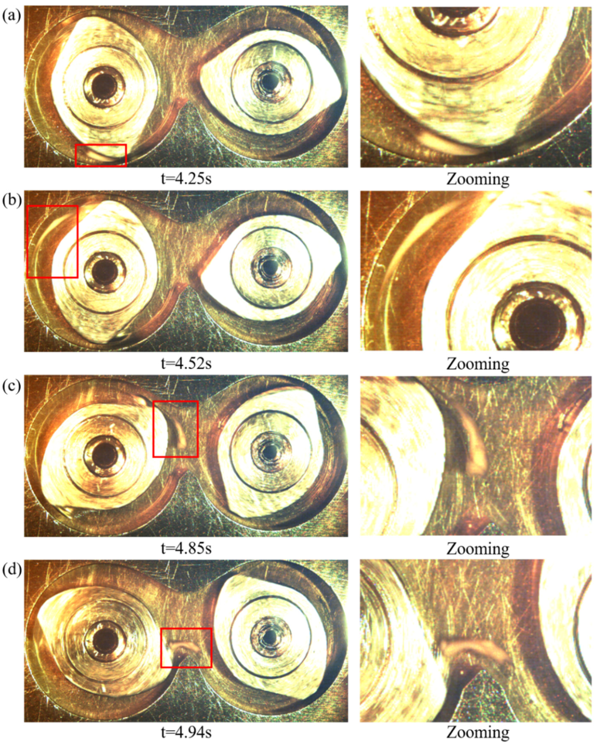
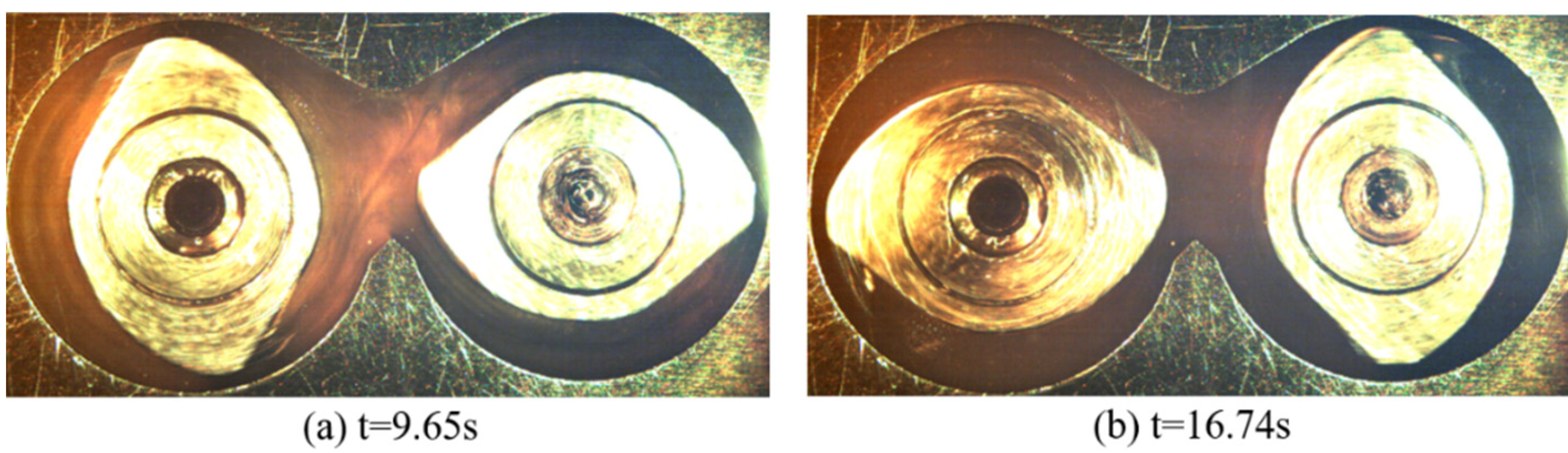
3.1. ABS Drop at 28.7 rpm

Figure 3 presented the initial situation and the erosion process of ABS drop in a modified batch mixer. To present the morphology of ABS drop in different moments clearly, the drop location in the left picture was marked with a red square, which was zoomed in the right picture. The rotor rotation speed was 28.7 rpm. At t = 11.58 s in Figure 3b, the ABS drop was transferred to the interaction window without any elongation deformation, but the ribbon connecting to the drop as a tail was formed at the drop surface. The formed ribbon indicated that the drop experienced the erosion process. According to the visualization results, the drop was sheared by the flow without going into the wedgelike region and passing through rotor tip clearance before t = 11.58 s. Thus, the shear effect originated from the flow and the friction effect between the drop and matrix made the drop surface soften. Furthermore, the adhesion between the drop surface and the inner part of the drop was relatively bad. Thus, the shear effect and the bad adhesion led to the drop surface peeling. A tailed ribbon connected to drop was formed as illustrated in Figure 3b.
ABS drop would keep experiencing the erosion process until the drop went into the wedgelike region and passed through the rotor tip clearance, where the drop exhibited different morphology development. Figure 4 presented the morphology development of ABS drop passing through the rotor tip clearance. At t = 14.98 s in Figure 4a, the drop had gone into the wedgelike region. The drop was squeezed to experiencing the elongation deformation and changed to a cone shape. According to existing knowledge, the shear effect suffered by drop would be much fiercer owing to the contraction structure in the wedgelike region. Besides, the efficient elongational flow component existed in the wedgelike region near the rotor tip. Thus, the drop would experience continuous elongation deformation once involved in the wedgelike region. Owing to the existence of pressure difference between the leading face and trailing face, the drop was pushed into the rotor tip clearance at t = 15.15 s as Figure 4b illustrating. The drop was further stretched and became a sticklike shape locating mostly in rotor tip clearance. In the clearance, the drop would suffer the fiercest shear effect and experience the elongation deformation continuously until passing through the clearance completely. At t = 16.24 s in Figure 4c, the drop had already passed through the clearance and became a much longer and slenderer sticklike shape than t = 15.15 s. When going into the wedgelike region and crossing the rotor tip clearance, the drop would experience the continuous elongation deformation under the effect of strong shear and elongational flow component.
Figure 5 presented the morphology development of ABS drop transferred into the interaction window. At t = 17.18 s in Figure 5a, the end of the sticklike drop near the rotor flat had already reoriented and folded. The reorientation and folding of the elongated drop in this domain resulted from the rolling poor existed in the domain near the rotor flat. At this moment, the drop was being transferred toward the interaction window. At t = 17.63 s in Figure 5b, the drop was completely transferred into the interaction window and further folded. Besides, the folded part would coalescence to reunion together. At t = 18.06 s in Figure 5c, the sticklike drop-in Figure 4c was totally folded. The folded part coalesced to form a new drop with slightly elongation deformation. At this moment, a new drop located in the domain over the barrier, and the two ends of the drop would move toward the left and right chamber according to the rotor rotation trend. At t = 18.37 s in Figure 5d, the new drop had been stretched in the domain over the barrier and became much longer and thinner than t = 16.24 s in Figure 4c. The elongated drop would be stretched continuously over the barrier and break into pieces when elongation deformation exceeding the limit. At t = 21.37 s in Figure 5e, two elongated drops located in different domains (locations A and B) were recorded. Two drops were originated from the breaking up of the drop in Figure 5d. One drop at location A had reoriented and was being transferred toward the interaction window. Another drop at location B was over the barrier and experiencing the elongation deformation.
Figure 6 presented the dispersion and distribution situation of ABS drop at t = 31.31 s and t = 52.43 s. At t = 31.31 s in Figure 6a, the spherical ABS drop-in Figure 3a had been dispersed into elongated threads. The threads were distributed in the whole flow field. At t = 52.43 s in Figure 6b, the LLDPE matrix were no longer transparent, and the ABS drop was hardly observed. Such a phenomenon proved that ABS drop had achieved a good distribution and dispersion state in the LLDPE matrix.
The morphology development of ABS drop from t = 0 s to t = 52.43 s revealed that the chaotic mixing held the dominate place in circumferential flow for a continuous mixer, and presented how an ABS drop went through the chaotic mixing. In the beginning, the drop experienced the erosion process without passing through the rotor tip clearance. Once the drop moved into the wedgelike region and passed through the rotor tip clearance, the drop would undergo obvious elongation deformation and would be elongated from sphere to a long and slender shape after leaving the clearance completely. The elongated drop would reorient, fold and coalesce together while transferred toward the interaction window. In the interaction window, the drop further folded and coalesced to form a new drop with slightly elongation deformation. Meanwhile, the new drop would be transferred to the domain over the barrier. The two ends of the new drop would be pushed into the left and right chamber, respectively. The new drop experienced the continuous elongation deformation and broke into pieces. Then, the broken pieces would repeatedly go through chaotic mixing in circumferential flow. In this way, the drop was dispersed and distributed in the matrix. The results also stating that the drop would experience the reorientation and folding only after experiencing the elongation deformation. Furthermore, the elongation deformation majorly existed in rotor tip clearance, wedgelike region, and domain over the barrier, while the reorientation and folding occurred in the domain near the rotor flat and interaction window.

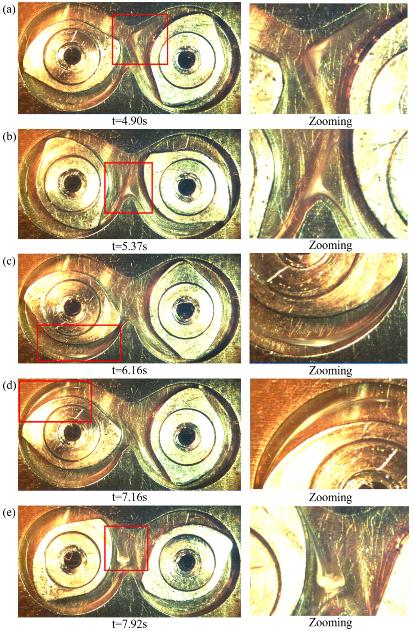
3.2. ABS Drop at 114.8 rpm

To consider the effect of rotor rotation speed on the chaotic mixing, the speed was set as 114.8 rpm. The morphology development of the ABS drop as illustrated in Figure 7. The initial location and shape of the drop were almost the same as in Figure 3a. At t = 4.25 s in Figure 7a, the drop was transferred into the wedgelike region and compressed to experience the elongation deformation. At t = 4.52 s in Figure 7b, the drop had passed through the rotor tip clearance completely and been elongated to a sticklike shape. At t = 4.85s in Figure 7c, the sticklike drop had already experienced the reorientation and folding process and coalesced together to form a new drop with slightly elongation deformation. At t = 4.94 s in Figure 7d, the new drop had been transferred to the domain over the barrier and would experience the continuous elongation deformation until breakup. At t = 9.65 s in Figure 8a, the drop had been dispersed into threads or small drops and distributed in the matrix. Such a state was similar to the situation at t = 31.31 s in Figure 6a. At t = 16.74 s in Figure 8b, the final dispersion and distribution of the drop were achieved. Thus, when rotor rotation speed was 114.8 rpm, the chaotic mixing was accelerated owing to experiencing the elongation deformation much earlier than 28.7 rpm. The elongation deformation also majorly existed in rotor tip clearance, wedgelike region, and domain over the barrier and the reorientation and folding occurred in the domain near the rotor flat and interaction window.
Interestingly, the erosion process of the ABS drop was not observed when the rotor rotation speed was 114.8 rpm even if five times trying with the same experiment condition. Basing on the erosion mechanism [7], the shear effect demanded sufficient time to soften the surface of the drop, which was one of the important factors that resulted in the occurrence of the erosion process. When the rotor rotation speed was 114.8 rpm, the drop would experience the first elongation deformation process at t = 4.25 s, which was much earlier than the situation when rotation speed was 28.7 rpm. So, the shear effect within such a short time could not soften the surface of the ABS drop. Thus, the erosion process of the drop was depressed when the rotor rotation speed was 114.8 rpm.

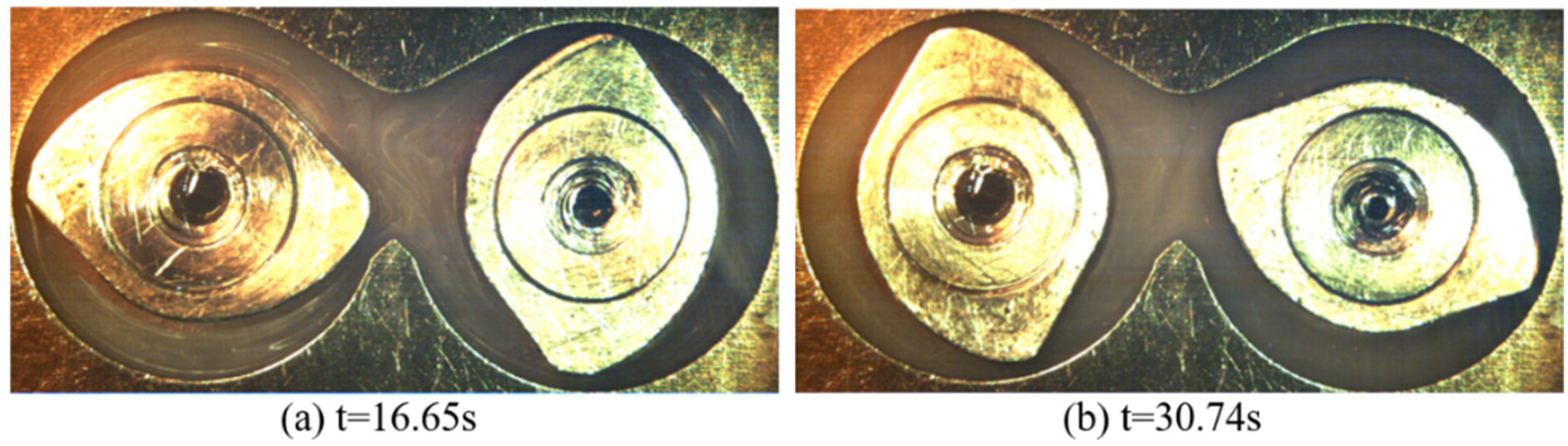
3.3. LLDPE/CaCO3 Drop at 28.7 rpm

To consider the influence of drop viscoelasticity on the chaotic mixing in a continuous mixer, the morphology development of viscous LLDPE/CaCO3 drop was presented in Figure 9, and the rotor rotation speed was 28.7 rpm. At t = 4.90s in Figure 9a, the elongation deformation of the LLDPE/CaCO3 drop was recorded without entering the wedgelike region and passing through rotor tip clearance. At the same time, the erosion process was recorded. Compared with ABS drop, the LLDPE/CaCO3 drop was more viscous, so the surface of the LLDPE/CaCO3 drop was much easier to be softened and eroded by the influence of shear. Meanwhile, the interface between the LLDPE matrix and LLDPE/CaCO3 drop was not unclear, so the interfacial slip was minimized during the mixing. The drop would easily undergo the elongation deformation without entering the wedgelike region and passing through rotor tip clearance. In Figure 9a, the elongational drop was folded in the interaction window. At t = 5.37 s in Figure 9b, the drop had been transferred to the domain over the barrier and would experience the continuous elongation, because the two ends of the drop moved toward the opposite direction. At t = 6.16 s in Figure 9c, the drop had been elongated to a long sticklike shape, and two ends of the drop were much slenderer than the middle. At t = 7.16 s in Figure 9d, the drop was in the flow domain before the leading face and stayed elongation deformation state. The drop end near the rotor flat became thicker than the situation in Figure 9c. Such a phenomenon was caused by the reorientation and folding effect existing in the flow domain near the rotor flat. Besides, the middle part of the drop was thinner, which indicates that the drop was still experiencing the elongation deformation while transferring. At t = 7.92 s in Figure 9e, the drop in Figure 9d had been folded and coalesced together in the domain over the barrier and would be continuously stretched in the next stage. Figure 10 illustrated the dispersion and distribution situation of LLDPE/CaCO3 drop at t = 16.65 s and t = 30.74 s. In Figure 10a, the LLDPE/CaCO3 drop had been dispersed into the matrix in the form of long threads. The long threads were distributed in the whole flow field. In Figure 10b, the long threads were further dispersed and distributed, and the LLDPE matrix became very opaque. This stated that the drop had been well dispersed and distributed in the LLDPE matrix.
For viscous LLDPE/CaCO3 drop, although the erosion process and elongation deformation were recorded at the initial stage of mixing, the drop still primarily experienced the chaotic mixing repeatedly in circumferential flow for a continuous mixer. Compared with the morphology development of ABS drop, the LLDPE/CaCO3 drop could go through the elongation deformation without entering the wedgelike region and passing through the rotor tip clearance. The drop maintained the elongation deformation until going into the interaction window, where the elongated drop would reorient and fold to form a coalesced drop over the barrier. Then, the coalesced drop would be continuously stretched until breakup. Although the LLDPE/CaCO3 drop did not pass through the rotor tip clearance completely, the wedgelike region and tip clearance also contribute to the elongation deformation. Besides, the LLDPE/CaCO3 drop could be well dispersed and distributed in the matrix at t = 30.74 s, which was shorter than ABS drop at the same rotation speed.
The chaotic mixing in circumferential flow for a continuous mixer was presented basing on the morphology development of ABS and LLDPE/CaCO3. The outstanding findings were summarized in Figure 11. The chaotic mixing was holding the dominant place in circumferential mixing. Elastic ABS drop and viscous LLDPE/CaCO3 drop both primarily experienced the elongation deformation, reorientation, and folding process repeatedly during the mixing. The elongation deformation existed majorly in the domain over the barrier, rotor tip clearance, and wedgelike region, and the reorientation and folding process mainly occurred in the domain near the rotor flat and interaction window.

4. Conclusions

In this paper, the chaotic mixing in circumferential flow for a continuous mixer was presented with tracing the morphology development of polymeric drops. The chaotic mixing was observed and analyzed with morphology development of the ABS drop and LLDPE/CaCO3 drop. The ABS drop and LLDPE/CaCO3 drop both experienced the elongation deformation, reorientation, and folding process, which were the important features of the chaotic mixing. Thus, the chaotic mixing was an essential and important mixing process in a continuous mixer. The domain over the barrier, rotor tip clearance, and wedgelike region were primarily responsible for the elongation deformation, and the domain near the rotor flat and interaction window mainly held the responsibility for the reorientation and folding process. The elongation deformation was a precondition that the drop experiencing the reorientation and folding process. Besides, the erosion process was recorded at the initial stage for both elastic ABS drop and viscous LLDPE/CaCO3 drop at a lower rotor rotation speed, while the higher rotor rotation speed would facilitate the chaotic mixing and depressing the erosion at the initial stage. The viscous LLDPE/CaCO3 drop would directly experience the elongation once the mixing initialed.

Author Contributions

Experimental work, T.C.; result evaluation and manuscript preparation, T.C. and G.L.; figure preparing and modification, T.C. and H.G.; review and editing, L.X. and Y.Y.; software and visualization, H.J. All authors have read and agreed to the published version of the manuscript.

Funding

This research was funded by the Construction Fund of International Joint Research Centre for Optoelectronic and Energy Materials by Yunnan Provincial Department of Finance (No. 2017IB033), the Yunnan University Action Plan of Serve the Yunnan Province (No. 2016MS15), and Yunling Scholars Fund of Yunnan Ten Thousand Talents Program (No. KC194317).

Conflicts of Interest

The authors declare no conflict of interest.

References

  1. García-Masabet, V.; Pérez, O.; Cailloux, J.; Abt, T.; Sánchez-Soto, M.; Carrasco, F.; Maspoch, L. PLA/PA Bio-blends: Induced morphology by extrusion. Polymers 2020, 12, 10. [Google Scholar] [CrossRef] [Green Version]
  2. Yin, B.; Zhao, Y.; Yu, R.; An, H.; Yang, M. Morphology Development of PC/PE blends during compounding in a twin-screw extruder. Poly. Eng. Sci. 2007, 47, 14–25. [Google Scholar] [CrossRef]
  3. Dong, T.; Jiang, S.; Wu, J.; Liu, H.; He, Y. Simulation of flow and mixing for highly viscous fluid in a twin screw extruder with a conveying element using parallelized smoothed particle hydrodynamics. Chem. Eng. Sci. 2020, 212. [Google Scholar] [CrossRef]
  4. Heeley, L.; Gough, T.; Hughes, J.; Bras, W.; Rieger, J.; Ryan, J. Effect of processing parameters on the morphology development during extrusion of polyethylene tape: An in-line small-angle X-ray scattering (SAXS) study. Polymer 2013, 54, 6580–6588. [Google Scholar] [CrossRef] [Green Version]
  5. Yin, B.; Lan, J.; Li, L.; Yang, M. Morphology evolution in PC/PE blends with and without compatibilization during twin-screw extrusion. Polym-Plast Technol. 2010, 49, 503–509. [Google Scholar] [CrossRef]
  6. Lin, B.; Mighri, F.; Huneault, A.; Sundararaj, U. Parallel breakup of polymer drops under simple shear. Macromol. Rapid Comm. 2003, 24, 783–788. [Google Scholar] [CrossRef]
  7. Lin, B.; Sundararaj, U.; Mighri, F.; Huneault, A. Erosion and breakup of polymer drops under simple shear in high viscosity ratio systems. Poly. Eng. Sci. 2003, 43, 891–904. [Google Scholar] [CrossRef]
  8. Lin, B.; Sundararaj, U. Sheet formation during drop deformation and breakup in polyethylene/polycarbonate systems sheared between parallel plates. Polymer 2004, 45, 7605–7613. [Google Scholar] [CrossRef]
  9. Mighri, F.; Huneault, A. In situ visualization of drop deformation, erosion, and breakup in high viscosity ratio polymeric systems under high shearing stress conditions. J. Appl. Polym. Sci. 2006, 100, 2582–2591. [Google Scholar] [CrossRef] [Green Version]
  10. Scott, E.; Macosko, W. Model experiments concerning morphology development during the initial stages of polymer blending. Polym. Bull. 1991, 26, 341–348. [Google Scholar] [CrossRef]
  11. Sundararaj, U.; Macosko, W.; Rolando, J.; Chan, T. Morphology development in polymer blends. Poly. Eng. Sci. 1992, 32, 1814–1823. [Google Scholar] [CrossRef]
  12. Scott, E.; Macosko, W. Morphology development during the initial stages of polymer-polymer blending. Polymer 1995, 36, 461–470. [Google Scholar] [CrossRef]
  13. Salahudeen, A.; Elleithy, H.; AlOthman, O.; AlZahrani, M. Comparative study of internal batch mixer such as cam, banbury and roller: Numerical simulation and experimental verification. Chem. Eng. Sci. 2011, 66, 2502–2511. [Google Scholar] [CrossRef]
  14. Li, H.; Sundararaj, U. Morphology development of polymer blends in extruder: The effects of compatibilization and rotation rate. Macromol. Chem. Phys. 2009, 210, 852–863. [Google Scholar] [CrossRef]
  15. Chen, T.; Hao, Y.; Chen, X.; Zhao, H.; Sha, J.; Ma, Y.; Xie, L. Mixing ability examination of three different rotor cross sections and rotor geometry quantification with pressurization coefficient. J. Appl. Polym. Sci. 2018, 135. [Google Scholar] [CrossRef]
  16. Min, K. Flow visualization of blending of elastomers and thermoplastics in an internal mixer. Adv. Polym. Tech. 1987, 7, 243–257. [Google Scholar] [CrossRef]
  17. Chen, H.; Sundararaj, U.; Nandakumar, K.; Wetzel, D. Erosion of polymer pellets during blending in a twin-screw extruder. AICHE J. 2006, 52, 1267–1270. [Google Scholar] [CrossRef]
  18. Chen, X.; Zhang, H.; Chen, T.; Zhao, H.; Ji, H.; Ma, Y.; Sha, J.; Xie, L. The solid-state mixing characteristic of two rotor continuous mixer and its influence on microstructure of HDPE/CaCO3 composite. Polym. Compos. 2019, 40, 3296–3305. [Google Scholar] [CrossRef]
  19. Valsamis, N.; Canedo, L. Mixing, devolatilization, and reactive processing in the a Farrel continuous mixer. Int. Polym. Proc. 1989, 4, 247–254. [Google Scholar] [CrossRef]
  20. Bang, S.; White, L. New model of flow in a Farrel continuous mixer. Poly. Eng. Sci. 1997, 37, 1210–1216. [Google Scholar] [CrossRef]
  21. Yao, C.; Manas-Zloczower, I. Influence of design on dispersive mixing performance in an axial discharge continuous mixer-lcmax 40. Poly. Eng. Sci. 1998, 38, 936–946. [Google Scholar] [CrossRef]
  22. Canedo, L.; Valsamis, N. Continuous mixer. In Mixing and Compounding of Polymers: Theory and Practice, 2nd ed.; Manas-Zloczower, I., Ed.; Hanser Publishers: Cincinnati, OH, USA, 2009; pp. 1104–1138. [Google Scholar]
  23. Dhakal, P.; Das, R.; Poudyal, H.; Chandy, J. Numerical simulations of partially-filled rubber mixing in a 2-wing rotor-equipped chamber. J. Appl. Polym. Sci. 2017, 134. [Google Scholar] [CrossRef]
  24. Galle, N.; White, L. Characterization of the behavior and blending performance of a continuous mixer. Int. Polym. Proc. 1999, 14, 241–246. [Google Scholar] [CrossRef]
  25. Lin, B.; Sundararaj, U. Visualization of poly(ether imide) and polycarbonate blending in an internal mixer. J. Appl. Polym. Sci. 2004, 92, 1165–1175. [Google Scholar] [CrossRef]
  26. Borzenski, J.; Valsamis, N. Optimizing mixing in the Farrel banbury mixer with wing function. Rubber World 2002, 226, 40–45. [Google Scholar]
  27. Avolio, R.; Gentile, G.; Avella, M.; Carfagna, C.; Errico, M. Polymer–filler interactions in PET/CaCO3 nanocomposites: Chain ordering at the interface and physical properties. Eur. Polym. J. 2013, 49, 419–427. [Google Scholar] [CrossRef]
  28. Avella, M.; Errico, M.; Gentile, G. PMMA based nanocomposites filled with modified CaCO3 nanoparticles. Macromol. Symp. 2007, 247, 140–146. [Google Scholar] [CrossRef]
  29. Avolio, R.; Castaldo, R.; Avella, M.; Cocca, M.; Gentile, G.; Fiori, S.; Errico, M. PLA-based plasticized nanocomposites: Effect of polymer/plasticizer/filler interactions on the time evolution of properties. Compos. Part. B-Eng. 2018, 152, 267–274. [Google Scholar] [CrossRef]
Figure 1. The cross-section view of the mixing chamber and rotors.
Processes 08 01308 g001
Figure 2. Shear rate versus viscosity for linear-low-density-polyethylene (LLDPE) at 200 °C.
Processes 08 01308 g002
Figure 3. The initial situation and the erosion process of acrylonitrile-butadiene-styrene (ABS) drop: (a) initial situation; (b) erosion process of ABS drop at t = 11.58 s.
Processes 08 01308 g003
Figure 4. Morphology development of ABS drop passing through the rotor tip clearance: (a) t = 14.98 s; (b) t = 15.15 s; (c) t = 16.24 s.
Processes 08 01308 g004
Figure 5. ABS drop deformation in the interaction window: (a) t = 17.18 s; (b) t = 17.63 s; (c) t = 18.06 s; (d) t = 18.37 s; (e) t = 21.37 s.
Processes 08 01308 g005
Figure 6. The dispersion and distribution situation of ABS drop at (a) t = 31.31 s and (b) t = 52.43 s when rotor rotation speed was 28.7 rpm.
Processes 08 01308 g006
Figure 7. The morphology development of ABS drop when rotor rotation speed was 114.8 rpm: (a) t = 4.25 s; (b) t = 4.52 s; (c) t = 4.85 s; (d) t = 4.94 s.
Processes 08 01308 g007
Figure 8. The dispersion and distribution situation of ABS drop at (a) t = 9.65 s and (b) t = 16.74 s when rotor rotation speed was 114.8 rpm.
Processes 08 01308 g008
Figure 9. The morphology development of LLDPE/CaCO3 drop when rotor rotation speed was 28.7 rpm: (a) t = 4.90 s; (b) t = 5.37 s; (c) t = 6.16 s; (d) t = 7.16 s; (e) t = 7.92 s.
Processes 08 01308 g009
Figure 10. The dispersion and distribution situation of LLDPE/CaCO3 drop at (a) t = 16.65 s and (b) t = 30.74 s when rotor rotation speed was 28.7 rpm.
Processes 08 01308 g010
Figure 11. The chaotic mixing in circumferential flow for a continuous mixer.
Processes 08 01308 g011
Publisher’s Note: MDPI stays neutral with regard to jurisdictional claims in published maps and institutional affiliations.

