In this section, we discuss the whole process of the online operation risk assessment of the wind power system of the CNN considering multiple random factors in detail. The core of the methodological model proposed in this paper is the training simulation and application of the convolution neural network. Therefore, the whole process of online operation risk assessment of the wind power system is introduced by reference to the entire process of the training simulation and application of the CNN. Firstly, we introduce the general framework process of online operation risk assessment. Then, the substructure of the general framework is described and constructed in detail. The specific details are as follows.
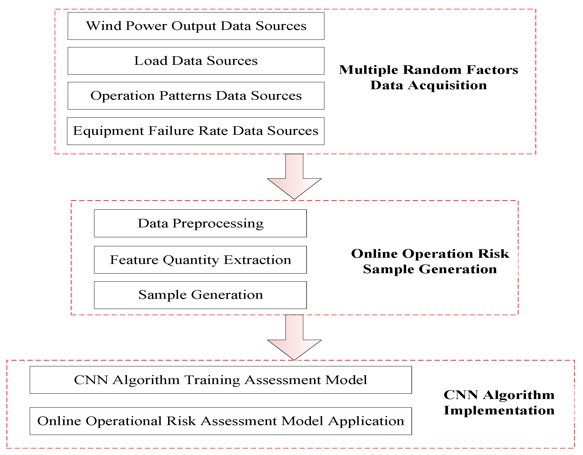
4.3. Online Operation Risk Sample Generation
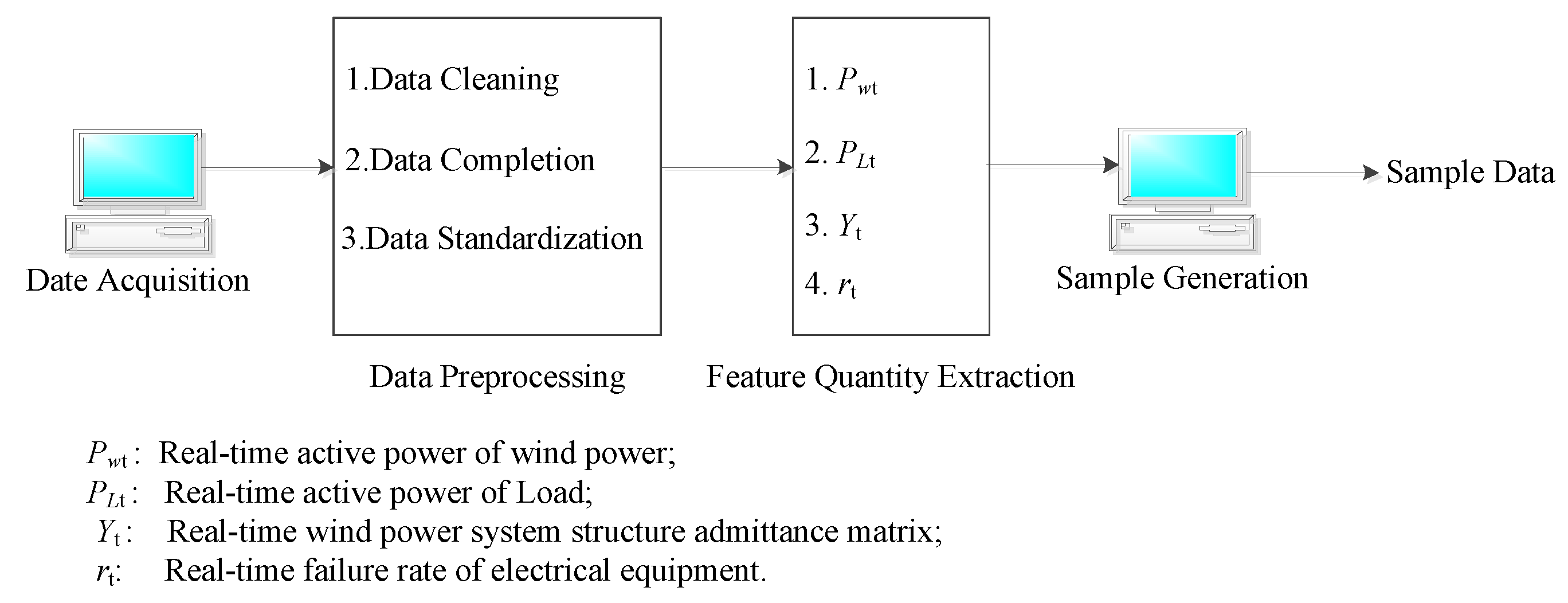
For the data obtained from the data, two steps are used to generate sample data through data preprocessing and feature extraction. The details are shown in
Figure 6.
In
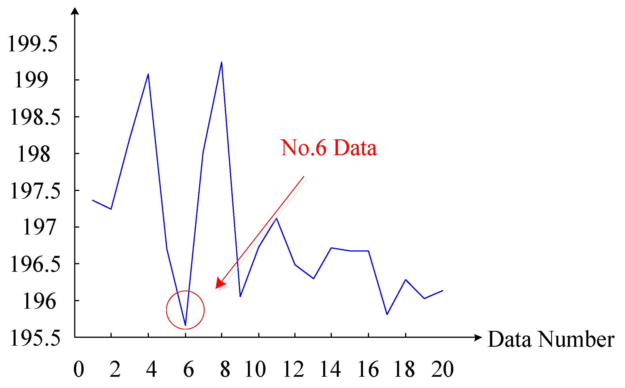
Figure 7, data preprocessing includes three main steps: (1) Data cleaning, in, which the acquired data is cleaned, and some obviously erroneous data are removed. For example, the data are displayed as “# # # #” and washed directly. (2) Data are made complementary data. In order to ensure the consistency of data dimensions, data that are not monitored or lost need to be supplemented. This paper adopts the mean complement method, that is, the average value of the sum of the previous moment data and the latter moment data, as the method of data at this moment. If the data is
xt-1 at the first moment and
xt+1 at the last moment, the data at the moment is
xt = 0.5*(
xt−1 +
xt+1). (3) Data are standardized. In order to unify the electrical equipment with a different capacity and to unify the electrical quantity, all electrical quantity is treated by a standard unit value.
In
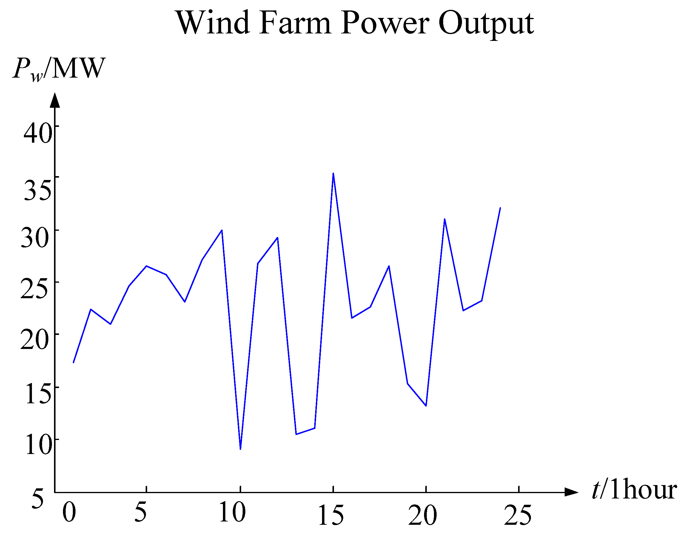
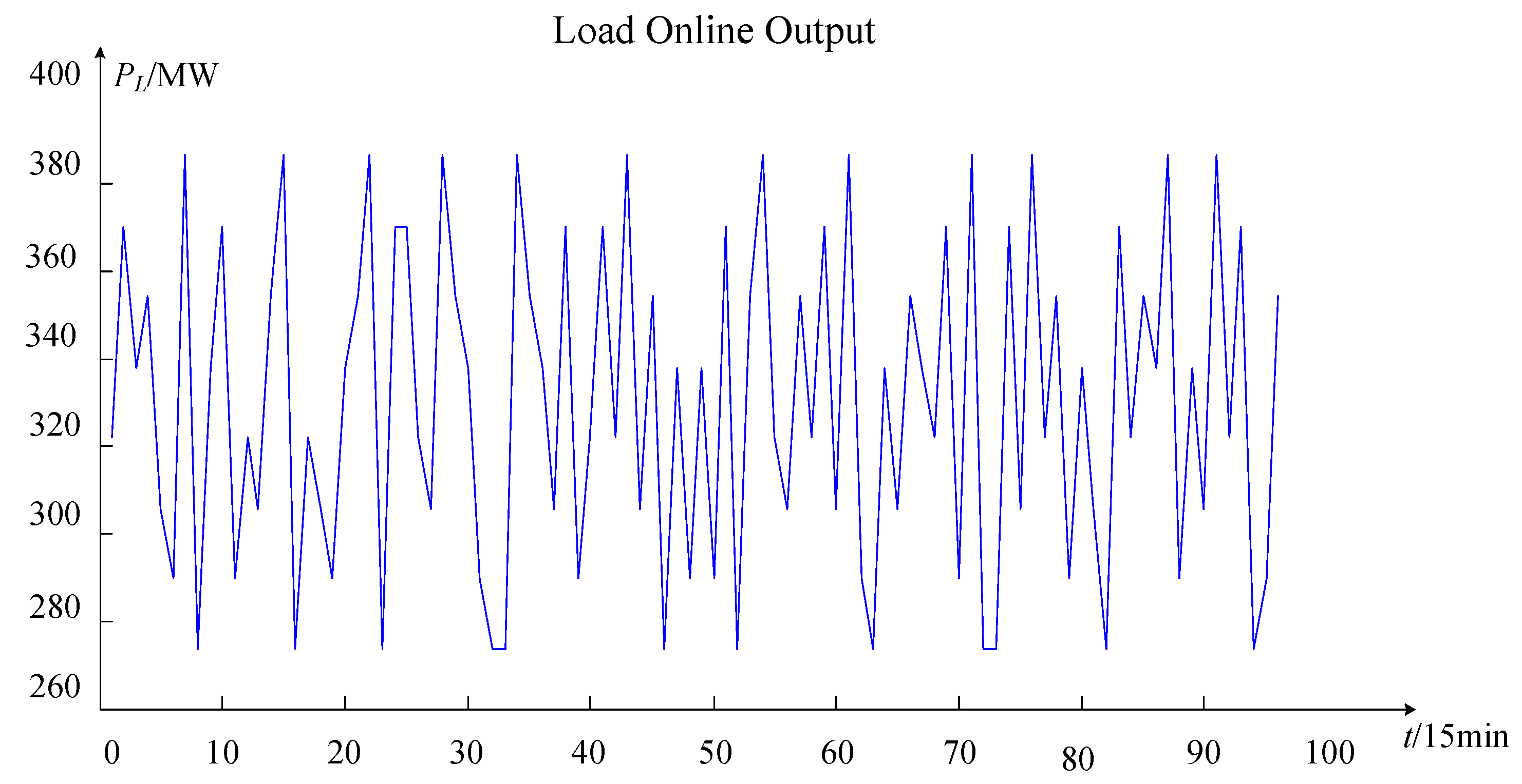
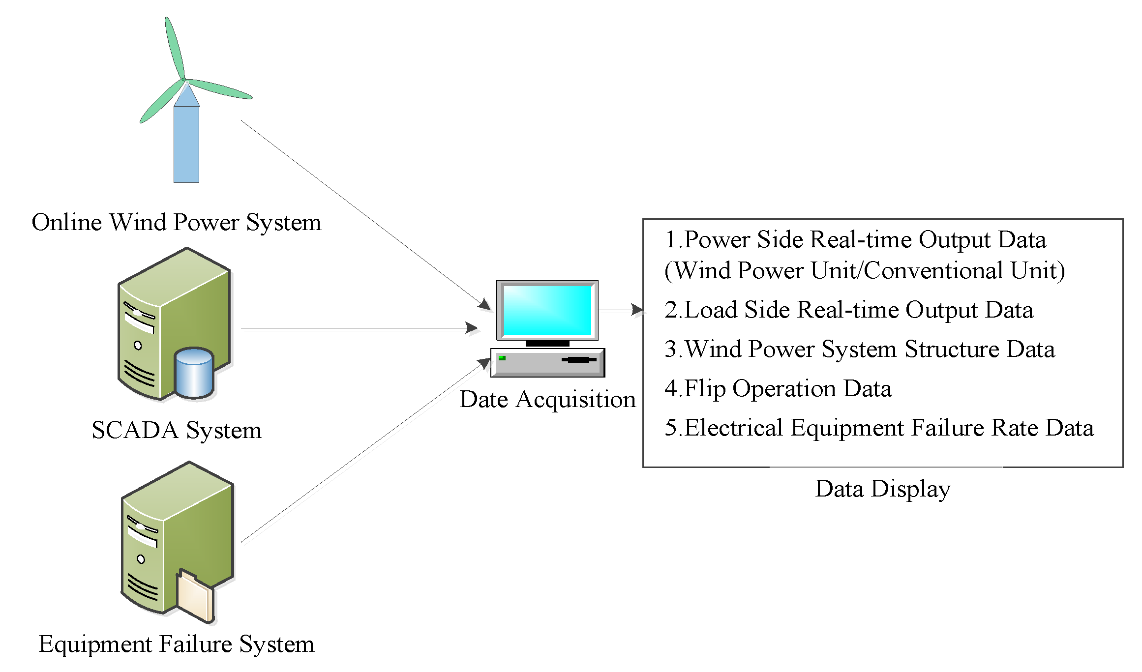
Figure 7, the features extracted from the online operation risk assessment of the wind power system in this paper include real-time wind power active power
Pwt, real-time active power
PLt, the real-time grid structure admittance matrix
Yt, and the real-time electrical equipment failure rate
rt. The real-time wind farm and the active power of the load can be directly extracted from the online wind power system and the SCADA system database. The failure rate of electric equipment can be extracted directly from the database of the electrical equipment fault system. However, the real-time admittance matrix cannot be extracted directly from the SCADA system. It is necessary to determine the admittance matrix of the real-time grid structure together with planned maintenance and electrical equipment fault information.
After the above processing, the data required for CNN training simulation were obtained. However, these cannot be used directly for the CNN training simulation and it is necessary to generate standard sample data from these data. The principles for generating sample data for online operation risk assessments are shown in
Figure 8.
In
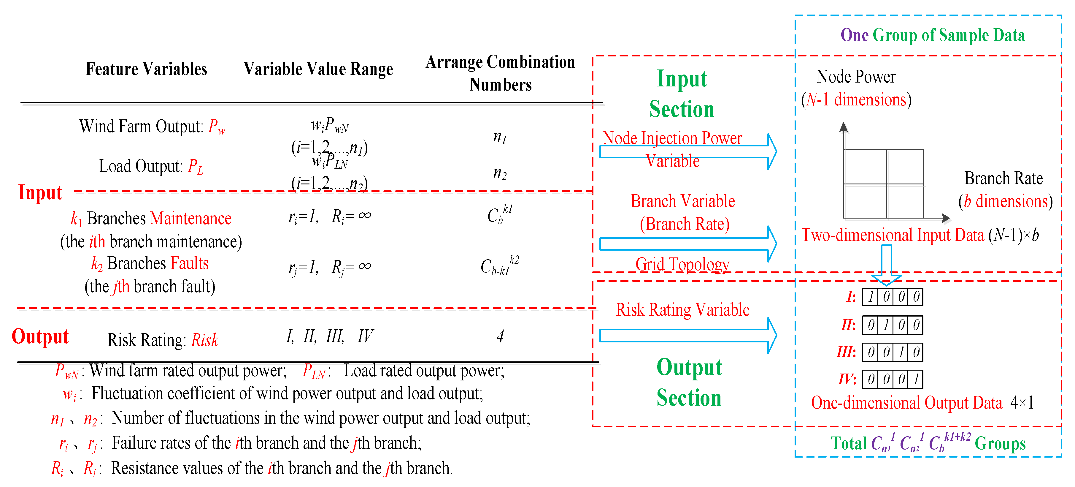
Figure 8, from left to right, the sample data generation principle diagram is mainly divided into two parts: The left part is the original data part and the right part is the standard sample data part.
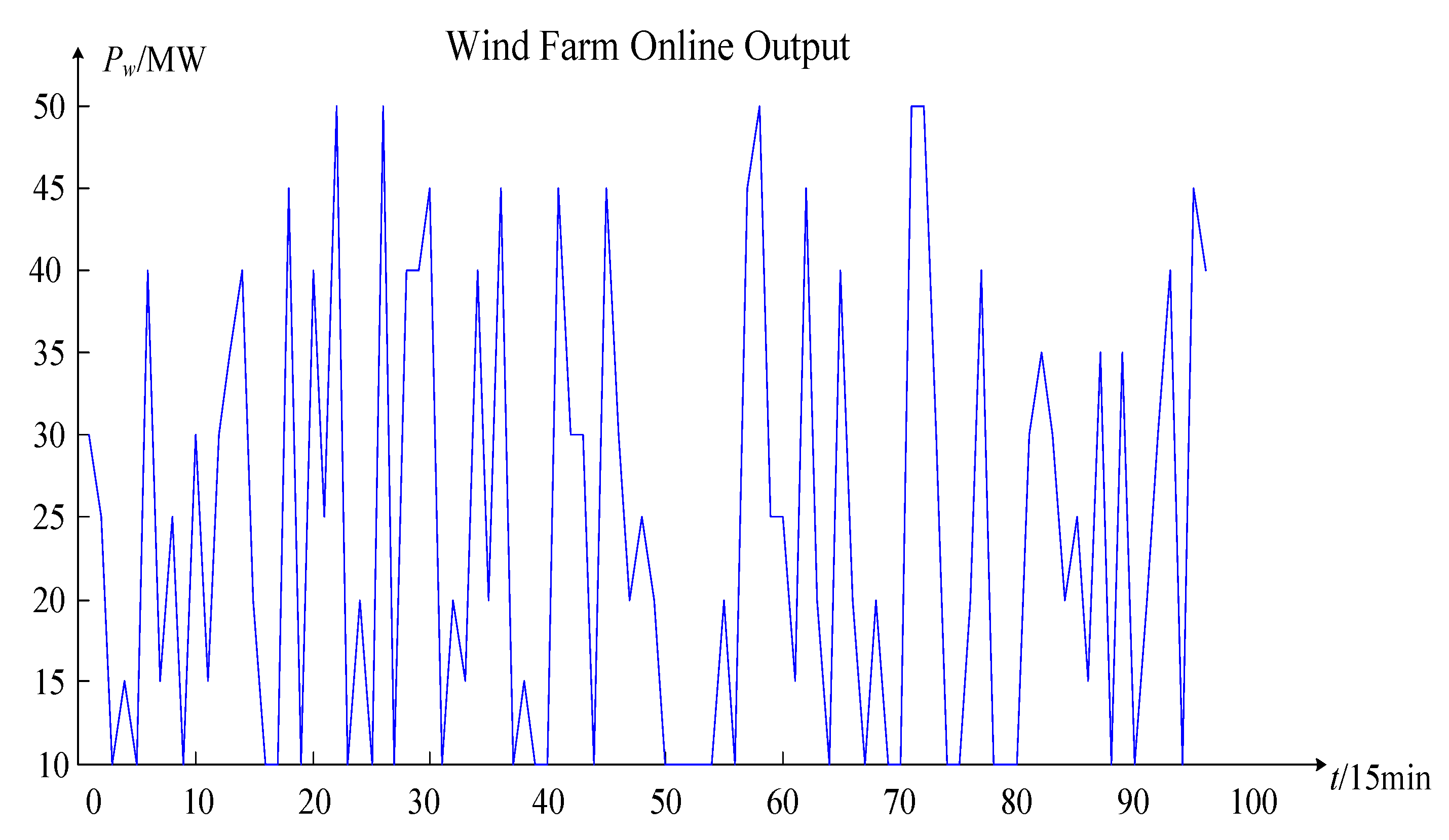
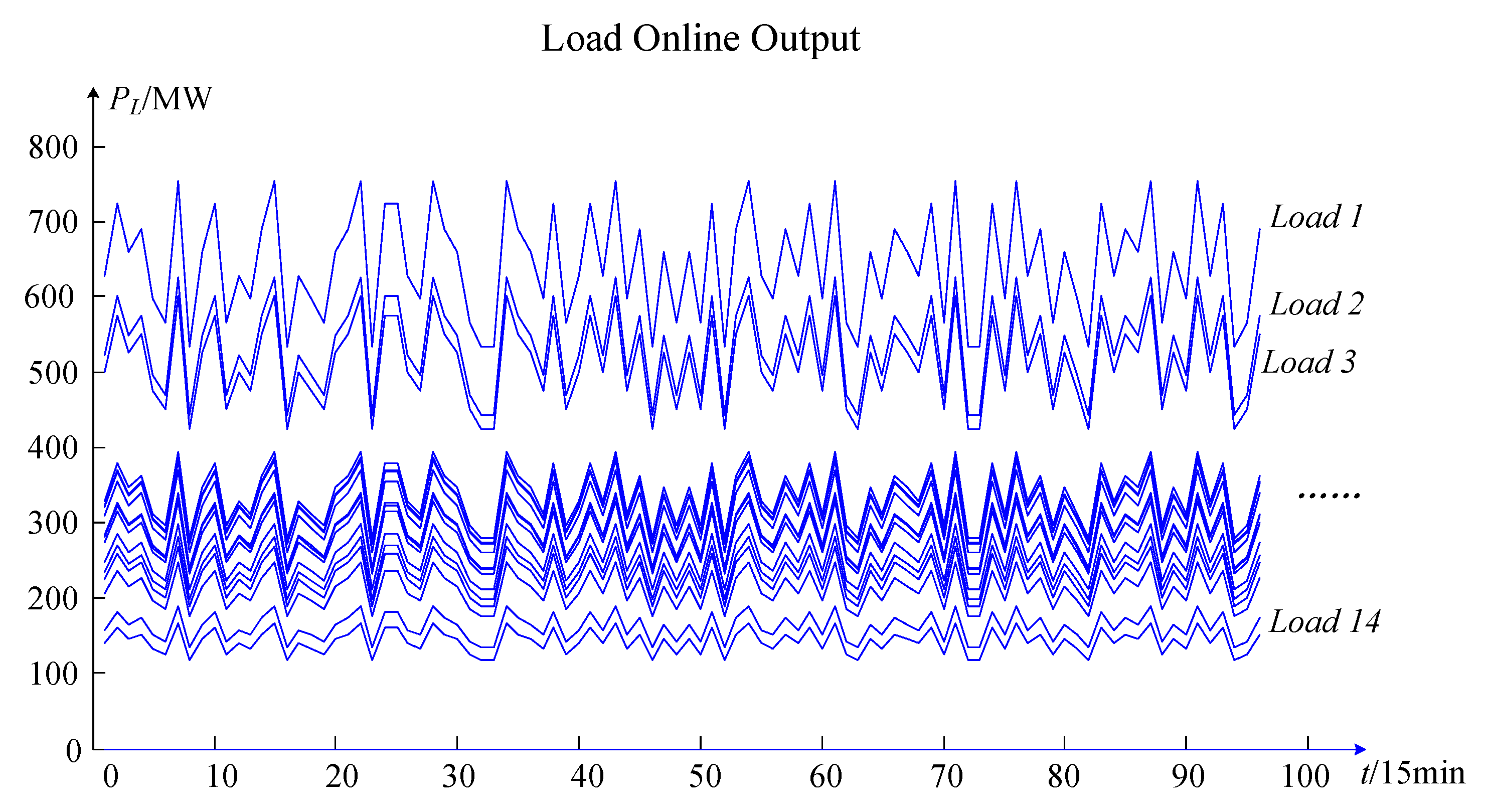
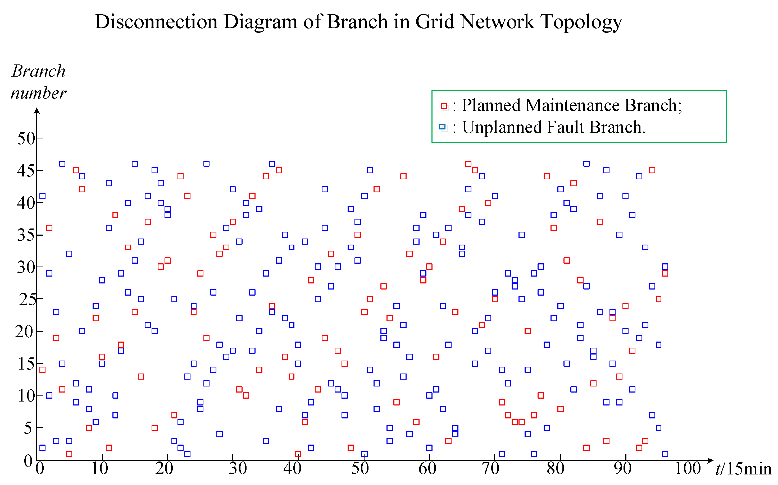
The original data part includes project contents such as feature variables, the variable value range, and the arranged combination numbers. From top to bottom, the original data part is divided into the input part and output part. The input part feature variables are the wind farm output (
Pw), load output (
PL), planned maintenance branches (
k1), and unplanned fault branches (
k2). The wind farm output and load output are classified into one category, which is called the node injection power variable. Since the wind farm access point and the load access point represent all nodes in the system grid network topology, when the wind farm output and load output change, it will only change the power of the injected node and will not change the structure of the system grid topology. Therefore, this type of variable is called a node injection power variable. The planned maintenance branch and the unplanned fault branch are classified into one category, which is called the branch variable. After the planned maintenance branch and the unplanned fault branch are determined, the corresponding branch will be disconnected from the system, thereby changing the structure of the system grid network topology. The branch break can be expressed by the mathematical formula as a failure rate 1 or the branch resistance is always infinite, so this type of variable is called a branch variable. The node injection power variable value range is the product of the proportional coefficient and the rated capacity. The arranged combination numbers are the proportional coefficient numbers. For example,
Pw =
wi ×
PwN,
PL =
wj ×
PLN,
wi and
wj are the proportional coefficient of the wind farm output and load output.
PwN and
PLN are the rated capacity of the wind farm output and load output. The number of
wi and
wj are
n1 and
n2, respectively. Therefore, the arranged combination numbers are
n1 and
n2, respectively. The branch variable value range is a constant value (failure rate is 1 and resistance is infinite). The arranged combination numbers are
Cbk1+k2.
k1 and
k2 are the numbers of planned maintenance branches and unplanned fault branches.
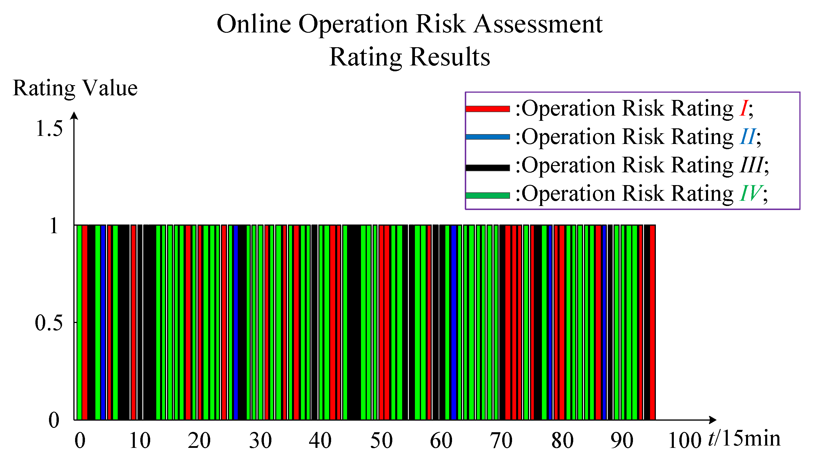
b is the sum number of wind power system branches. The output part represents the expected targets of online operation risk assessment, such as
Section 2.5 in this paper. The output part feature variable is the risk rating (
Riski). The output part variable value ranges are
I,
II,
III, and
IV. Referring to
Table 1,
I indicate that the risk rating is a general accident,
II indicates that the risk rating is a larger accident,
III indicates that the risk rating is a major accident, and
IV indicates that the risk rating is a particularly significant accident. The arranged combination number of the output part is four. This means that there are only four levels of the online operation risk rating.
The standard sample data part is the standard data that can be directly entered into the CNN algorithm for training simulation. From top to bottom, the standard sample data part is divided into the input part and output part. The input and output parts of the standard sample data correspond to the input and output parts of the original data. In the standard data part, the input part is a two-dimensional matrix data. In the two-dimensional data, the x-axis data represents the branch electrical equipment failure rate data, and y-axis data represents the node injection power data. The x-axis data reflects the failure rate of electrical equipment in all branches. The failure rate of planned maintenance branches and unplanned fault branches are constant at 1, and the failure rate of the remaining branches is the failure rate of equipment on the corresponding branch roads. The y-axis data reflects the injected power data of all nodes. The node injection power is the power supply output minus the load output, in which the power supply output includes the output of the conventional unit and the output of the wind farm. The two-dimensional matrix data of the input part of the standard sample data can be expressed as (N − 1) × b. N is the number of nodes of the wind power system and b is the number of branches of the wind power system. In the power flow calculation, a node is required to balance the power and serve as a reference point for the node voltage. This node is called a balance node, and the balance node does not participate in the power flow calculation. For a wind system with N nodes, the injection power of up to N − 1 nodes can be adjusted, so the input part data is expressed as (N − 1) × b instead of N × b. The output part is one-dimensional matrix data. There are only four possible output data in the output part, namely I, II, III, and IV. Among them, I is denoted as 1000, II is denoted as 0100, III is denoted as 0010, and IV is denoted as 0001. The input two-dimensional matrix data and output one-dimensional matrix data form a set of online operation risk standard sample data. A set of sample data represents the scene of an online operation risk assessment of the wind power system. The number of sample data groups is equal to the number of scenes. The number is related to the arranged combination number of multiple random factors. The total number of standard sample data groups is Cn11 Cn21Cbk1 + k2. n1 and n2 are the arranged combination number of the wind farm output and load output, respectively; k1 and k2 are the numbers of planned maintenance branches and unplanned fault branches, respectively; and b is the sum number of wind power system branches.
In summary, according to this sample data generation principle diagram, the standard sample data of the online operation risk assessment of the wind power system can be obtained, and the next step of the CNN algorithm is then implemented.
4.4. CNN Algorithm Implementation
CNN algorithm implementation is mainly divided into two steps. The first step is to construct the optimal CNN algorithm network structure. The second step is to apply the CNN training model. The first step is to build a variety of CNN algorithm network structures. Through the online operation sample data for offline training simulation, the optimal CNN algorithm network structure, that is, the online operation risk assessment model of the wind power system, can be found. The second step uses the evaluation model completed by CNN offline training, adopts online data, and applies the CNN training model online to provide the operator with the real-time online wind power system risk status.
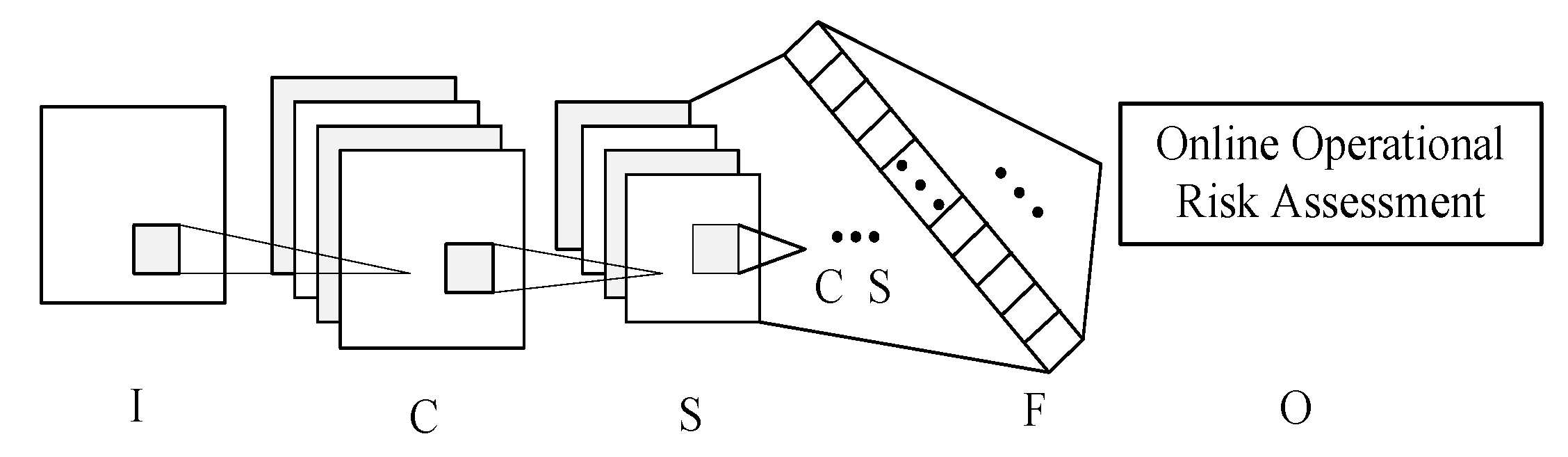
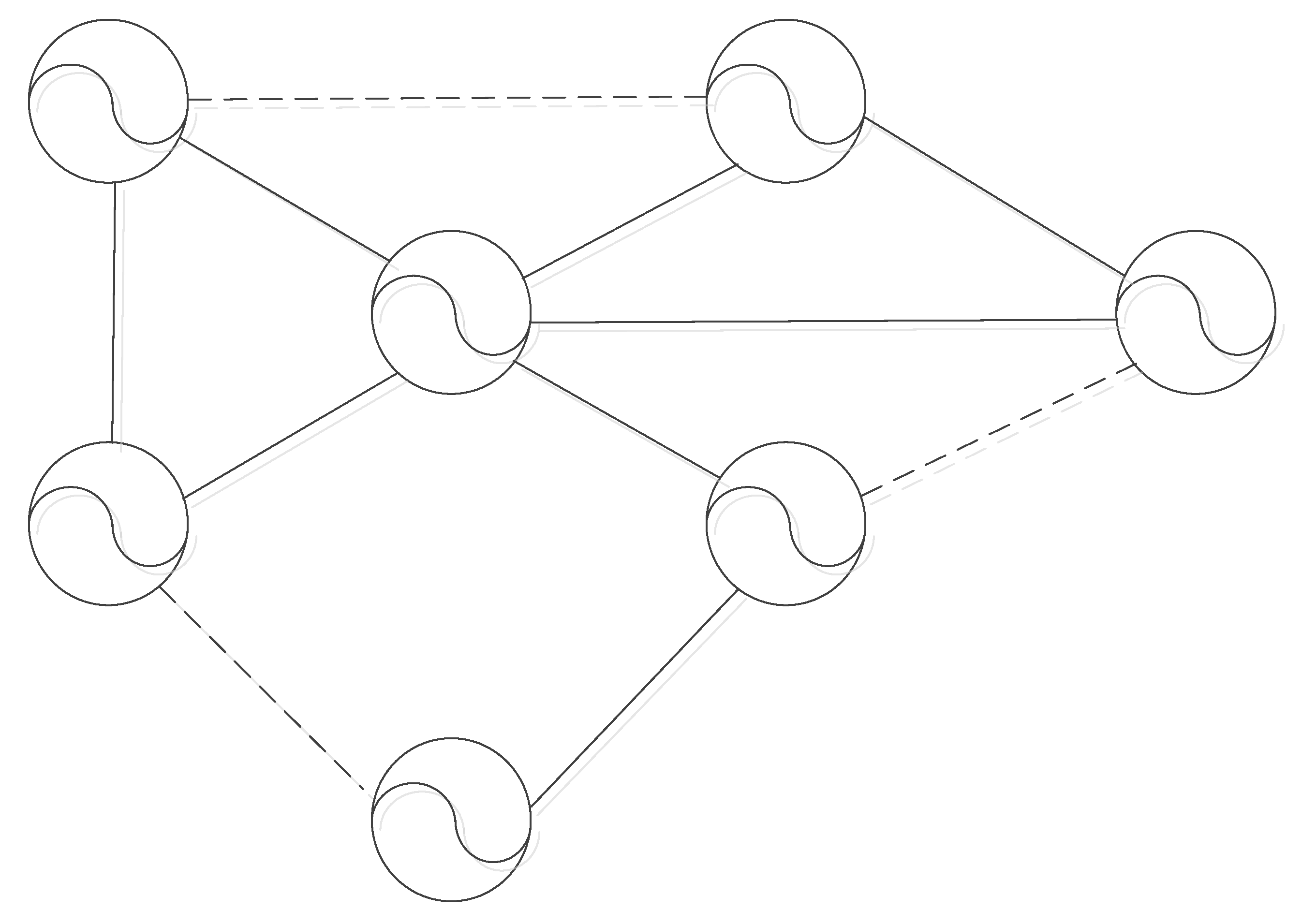
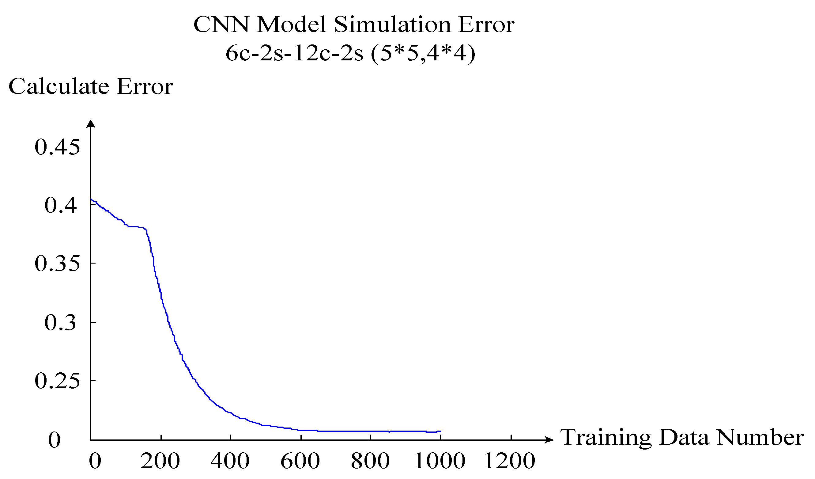
The key to the first step is how to construct the CNN algorithm network structure. The CNN algorithm network structure includes four layers: The input layer, convolution layer, sampling layer, and output layer. The English 10-machine 39 node systems are used to explain how to construct the CNN algorithm network structure. An optimal CNN algorithm network structure is shown in
Figure 9.
In
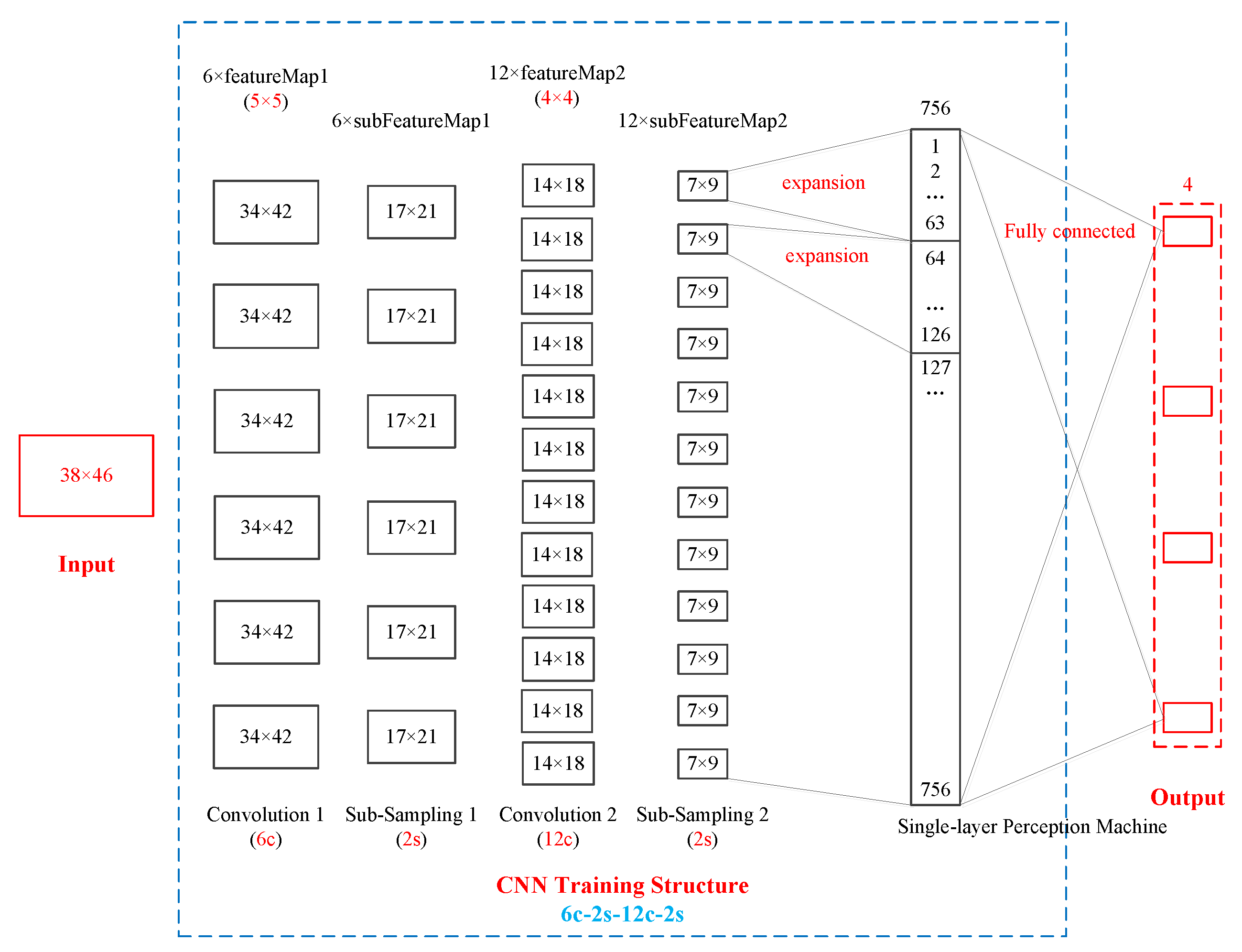
Figure 9, the red box parts on the left and right represent the input layer and the output layer, and the blue box parts in the middle represent the convolution layer and the sampling layer. Judging from the overall structure of the CNN network, there is only one input layer and one output layer, but there can be many convolution layers and sampling layers. In the English 10-machine 39 node system, there are 39 nodes and 46 branches. Therefore, the input data structure is 38 × 46, and the output data structure is 1 × 4. In this CNN network structure, there are two convolution layers and two sampling layers that appear in pairs. The CNN network structure is 6c-2s-12c-2s. 6c indicates that the first convolution layer has six layers. 2s represents the first sub-sampling layer, and the sub-sampling layer and the convolution layer appear in pairs, so the first sub-sampling layer also has six layers, and the first sub-sampling layer data scale is 1/2 of the first convolution layer. 12c indicates that the second convolution layer has 12 layers. 2s represents the second sub-sampling layer, and the sub-sampling layer and the convolution layer appear in pairs, so the second sub-sampling layer also has 12 layers, and the second sub-sampling layer data scale is 1/2 of the second convolution layer.
Taking the English 10-machine 39 node system data as an example, the variation of data from the input layer to output layer is introduced. The input data structure is 38 × 46. After the first convolution layer with a feature structure of 5 × 5, the data structure becomes 34 × 42. The law of data structure change is as follows: 34 = 38 − 5 + 1; 42 = 46 − 5 + 1. After the first sub-sampling layer with a 2s structure, the data structure becomes 17 × 21. The law of data structure change is as follows: 17 = 34/2; 21 = 42/2. After the second convolution layer with a feature structure of 4 × 4, the data structure becomes 14 × 18. The law of data structure change is as follows: 14 = 17 − 4 + 1; 18 = 21 − 4 + 1. After the second sub-sampling layer with a 2s structure, the data structure becomes 7 × 9. The law of data structure change is as follows: 7 = 14/2; 9 = 18/2. Next, the 12-layer sampling layer two-dimensional matrix data is expanded to single one-dimensional data of the single-layer perception machine. The law of data structure expansion is as follows: 1st 7 × 9 → 1, 2, …, 63; 2nd 7 × 9 → 64, 65, …, 126; …; 12th 7 × 9 → 694, 695, …, 756. Finally, full connection between the 756 sets of data in the single-layer perception machine and the four sets of data in the output layer is established. Here, using the CNN algorithm, a set of sample data from the input layer to the output layer of the entire process of a CNN training simulation can be obtained. Multiple sets of sample data constantly repeat this training simulation process. The optimal CNN algorithm network structure is found by changing the structural parameters of the convolution layers and the sub-sampling layers. In summary, the first step is to complete and obtain the optimal CNN algorithm network structure through offline training. The optimal CNN algorithm network structure model is the online operation risk assessment model of the wind power system.
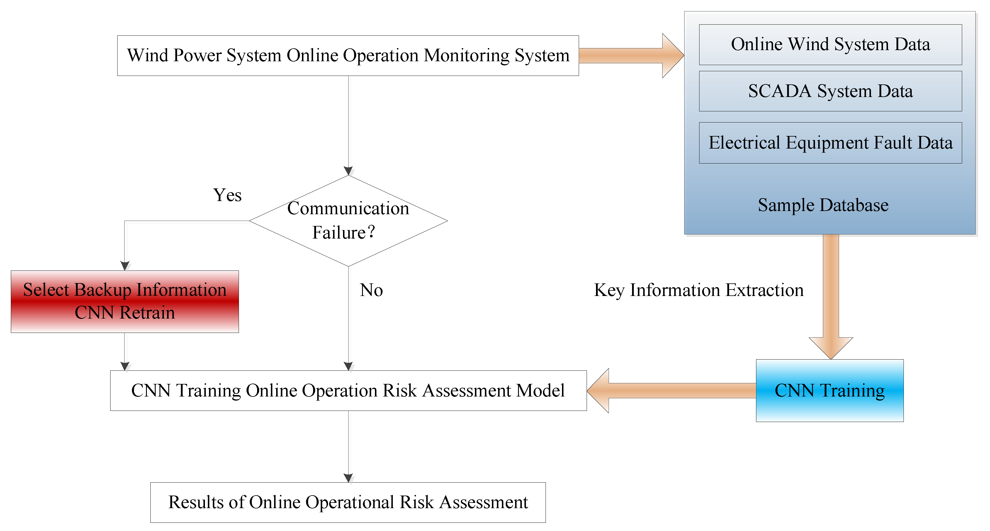
After obtaining the online operation risk assessment model, the second step is to apply the CNN training risk assessment model. The application of the CNN training model in the online operation risk assessment of wind power systems is shown in
Figure 10.
In
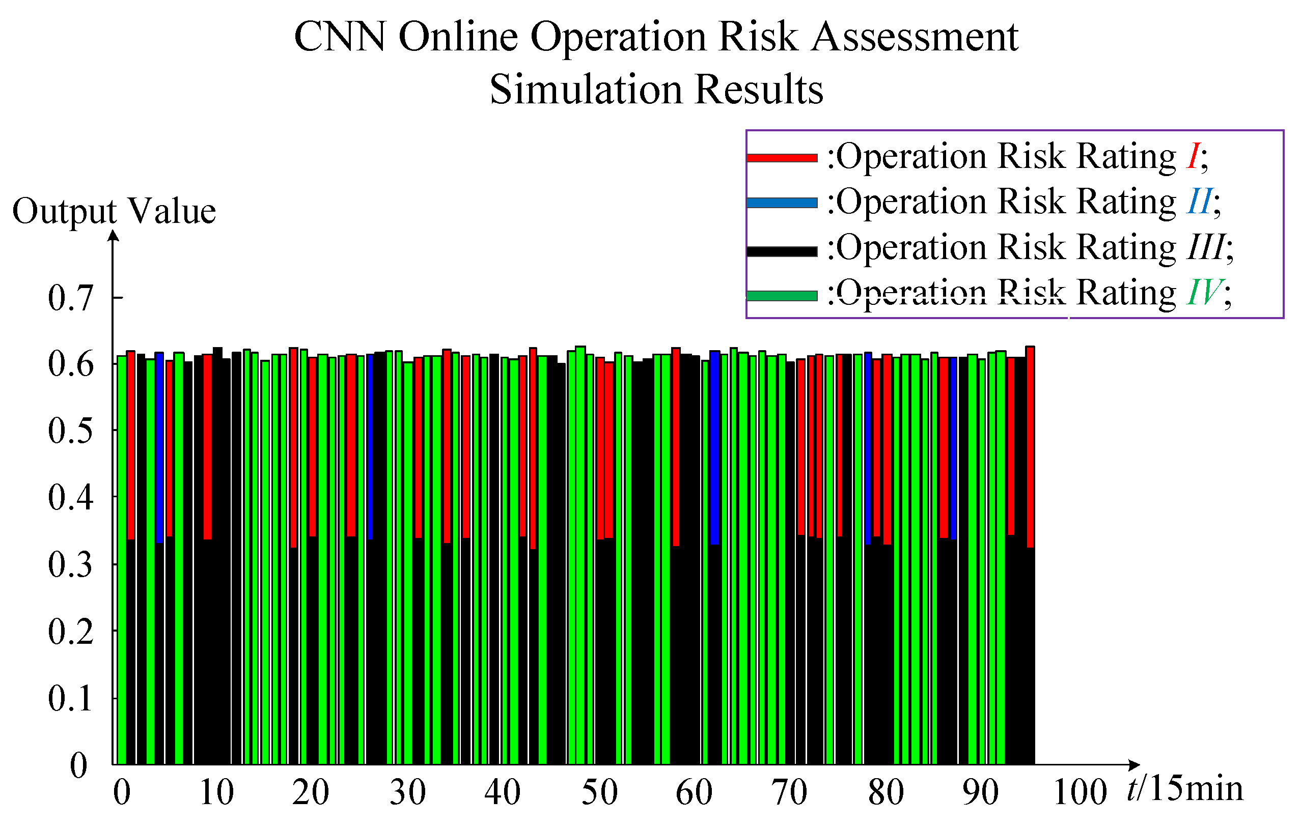
Figure 10, the application of the CNN training model consists of three main parts: Real-time data input for wind power system online monitoring data, the CNN training risk assessment model, and the results of online operation risk assessment. The real-time data input is real-time data with multiple random factors. Real-time data includes the wind farm output, load output, operation pattern, and electrical equipment failure rate. The CNN training risk assessment model is the optimal online operation risk assessment model for the completion of previous offline training. The results of online operation risk assessment are four calculated values in positions 1, 2, 3, and 4, respectively. For the maximum value in the first position, the risk rating is
I; for the maximum value in the second position, the risk rating is
II; for the maximum value in the third position, the risk rating is
III; and for the maximum value in the fourth position, the risk rating is
IV. In this way, it can reflect the online operation risk assessment of wind power system in real time.
In addition, after considering multiple random factors to ensure the accuracy of the risk assessment model, in the implementation of the CNN algorithm, the online operation risk assessment model of the wind power system is offline training, and the online application assessment model evaluates the operational risk in real time. Due to the direct application of offline training models in online applications and maintenance of the risk assessment model during the evaluation process, the time required for online running of the risk assessment is greatly shortened, which is conducive to the online application of the model.


