Article

Numerical Study on the Gas-Water Two-Phase Flow in the Self-Priming Process of Self-Priming Centrifugal Pump

1
School of Hydraulic, Energy and Power Engineering, Yangzhou University, Yangzhou 225002, China
2
Department of Energy and Power Engineering, Tsinghua University, Beijing 100084, China
3
Research Center of Fluid Machinery Engineering and Technology, Jiangsu University, Zhenjiang 212013, China
*
Authors to whom correspondence should be addressed.
Processes 2019, 7(6), 330; https://doi.org/10.3390/pr7060330
Submission received: 30 April 2019 / Revised: 26 May 2019 / Accepted: 29 May 2019 / Published: 1 June 2019
(This article belongs to the Special Issue Smart Flow Control Processes in Micro Scale)

Abstract

:
A self-priming centrifugal pump can be used in various areas such as agricultural irrigation, urban greening, and building water-supply. In order to simulate the gas-water two-phase flow in the self-priming process of a self-priming centrifugal pump, the unsteady numerical calculation of a typical self-priming centrifugal pump was performed using the ANSYS Computational Fluid X (ANSYS CFX) software. It was found that the whole self-priming process of a self-priming pump can be divided into three stages: the initial self-priming stage, the middle self-priming stage, and the final self-priming stage. Moreover, the self-priming time of the initial and final self-priming stages accounts for a small percentage of the whole self-priming process, while the middle self-priming stage is the main stage in the self-priming process and further determines the length of the self-priming time.

1. Introduction

A pump is a kind of general machine with tremendous variety and extensive application fields, and it can be said that pumps serve in all places with liquid flow [1,2,3,4]. According to statistics, the power consumption of pumps account for 22% of the power generation and the oil consumption accounts for about 5% of the total oil consumption [5,6,7,8,9,10]. Self-priming centrifugal pumps, or self-priming pumps, have no bottom valve in the inlet pipe. The pump structure is changed such that it can store some water after stopping and exhaust the air in the inlet pipe at the start by the mixture and separation of air and water. The water returns to the appropriate position in the pump via the backflow channel, and the above process is repeated, thereby realizing the self-priming. The process requires a water supply only at the initial stage; no water supply is necessary in subsequent start-ups. After a short operating period, the pump itself can suck up the water and be put into normal operation. A self-priming pump is easy to operate and has stronger adaptability than an ordinary centrifugal pump. Such a pump is extremely suitable for situations with frequent start-ups or difficult liquid irrigations [11,12,13,14,15,16]. Self-priming is an important parameter in order to evaluate the performance of self-priming pumps, and it determines the normal operation of pumps. According to the Chinese standard JB/T6664-2007, the self-priming time of a 5 m vertical pipe should be controlled within 100 s. Given that the self-priming process of a self-priming pumps is a complicated, unsteady gas–liquid flow phenomenon, studying the self-priming performance of pumps is difficult. Moreover, many challenges emerge in the study of the influencing factors of the self-priming time of self-priming pumps.
Many studies on the self-priming process of self-priming centrifugal pumps have been conducted by theoretical calculation, numerical calculation, and test measurement; certain research results have also been obtained. Using theoretical calculations, Zhao et al. [17] deduced the formulas of self-priming time and exhaustion rate according to fluid mechanics, thermodynamics, air dynamic equation, and energy invariant equation cited in their studies of vertical self-priming centrifugal pumps. Yi [18] summarized the data about self-priming time and the specific speed of 31 modes of external-mixture self-priming centrifugal pumps and explored the corresponding rules and trends. However, the self-priming time gained from the relevant calculation formula had a great range and only had statistical significance. Although the proposed theoretical calculation of self-priming time is not highly accurate and has narrow applicability, the theoretical calculation process indicates that moving bubbles are the relevant results of the main media accomplished by self-priming. Using numerical calculation, Wang et al. [19,20] adopted an inlet void fraction of 15% for the self-priming process of rotational flow of a self-priming pump using Fluent software. They found that the liquid phase drove the gas phase flow by phase interaction during the self-priming process and finally obtained the self-priming time. Using the Fluent software, Liu et al. [21,22] made a numerical calculation of the gas-water two-phase flow in the self-priming process of a single-stage self-priming centrifugal pump, and the pressure, velocity and gas distribution of the flow field under different assumed void fraction conditions were obtained. However, the exact void fraction in the pump inlet was unknown. Li et al. [23,24] simulated the gas–liquid states in a pump at different moments (initial, middle, and late stages) of the self-priming process using the quasi-steady method with a decreased void fraction, and then estimated the time required for the entire self-priming process. However, such a quasi-steady method is markedly different from the real self-priming process. For the numerical calculation of the self-priming time of self-priming pumps, scholars hypothesized that either the inlet void fraction of a pump comprised several fixed numerical values (5%, 10%, and 15%) and the velocity inlet was set or gas filled the entire pump inlet and the gas inlet velocity was a mean value. The former hypothesis was not based on the self-priming numerical calculation of self-priming pumps but on the numerical simulation of ordinary gas–liquid flow pumps. The latter hypothesis was close to the real self-priming situation, but it assumes that the velocity inlet was an average, which obviously contradicted the inversely V-shaped variation of self-priming speed in the self-priming process. The study of Huang et al. [25] was the closest to the real simulation of the self-priming time of a single-stage self-priming pump because they did not set the velocity inlet or mass outlet in the simulation process. However, the relevant calculation model only hypothesized that the self-priming height was 0.25 m. This result was inconsistent with the vertical self-priming height of 3 or 5 m in the real self-priming process, thereby failing to reflect the flow rule of the whole self-priming process. With regard to experimental measurements, existing studies mainly focused on the influences of structural improvement [26], volume of fluid reservoir [27], area and position of backflow hole [28], and tongue gap [29] of self-priming pumps on self-priming time.
In summary, the existing numerical calculations of the self-priming process in self-priming pumps are not precise, and relevant experimental studies on the self-priming process are scarce. Thus, it’s very necessary to study the unsteady flow of the self-priming process through numerical methods. In the current study, a typical self-priming centrifugal pump was designed, and a numerical calculation of the gas-water two-phase flow in the self-priming process was performed using the ANSYS CFX.

2. Methodology

2.1. Three-Dimensional Model of the Impeller and Diffuser

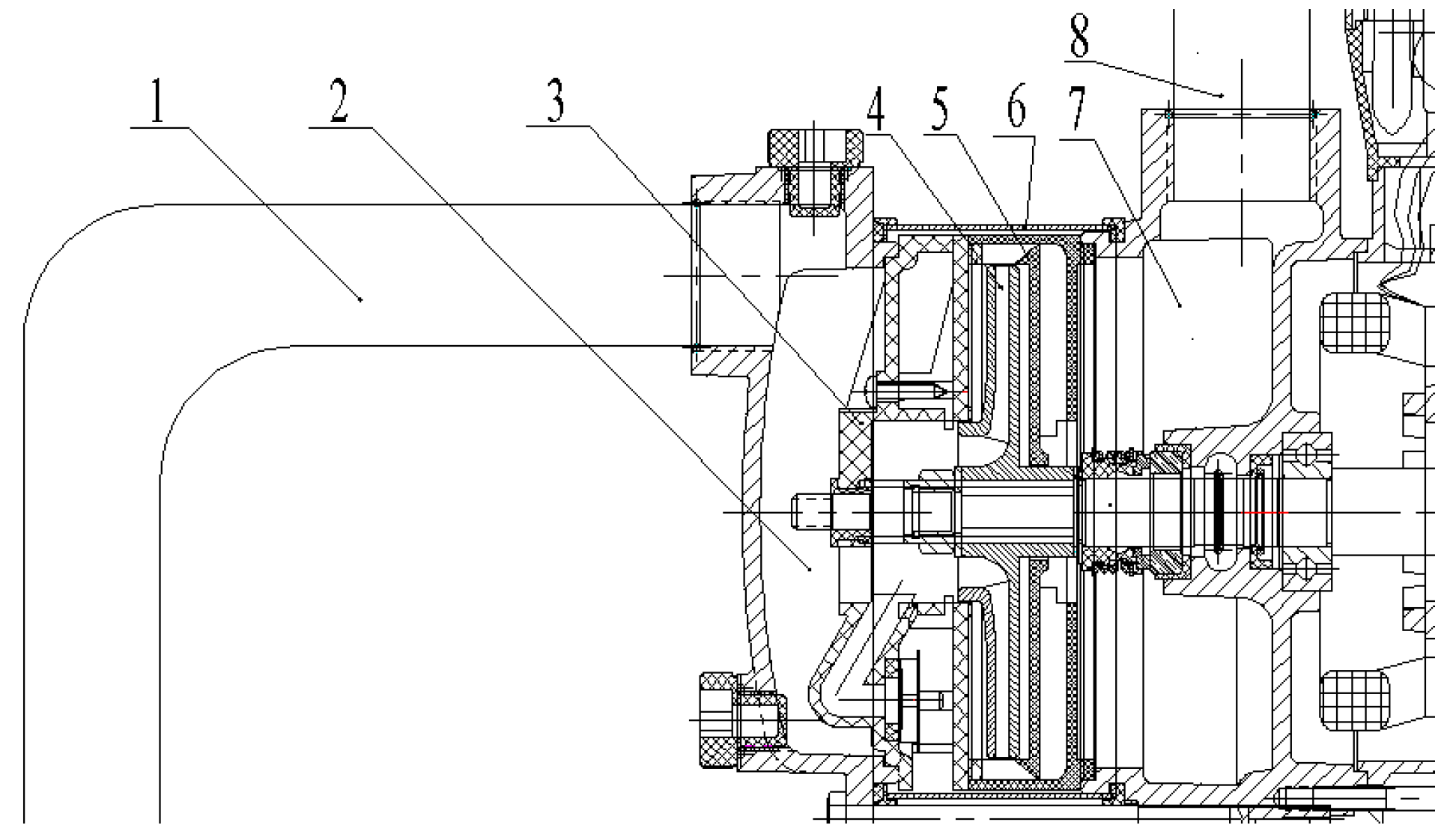
In this study, a motor direct connection mode in the self-priming pump is used with a compact structure and easy installation and operation. The entire pump is composed of inlet and outlet pipes, gas–liquid mixture cavity, self-priming cover plate, impeller, diffuser, outer casing, shaft, gas–liquid separation cavity, and a motor, among others (Figure 1). Moreover, the core components of the self-priming pump include the impeller and diffuser, whose geometric parameters are calculated by using the velocity coefficient method, which is shown in Table 1. The three-dimensional models and practical pictures of the impeller and diffuser are shown in Figure 2, respectively.

2.2. Establishing the Calculation Domain

As shown in Figure 3, the calculation domain of the multistage self-priming pump includes inlet section, gas-water mixture cavity, self-priming cover plate, impeller, pump cavity, diffuser, gas-water separation cavity, backflow channel and outlet section. The inlet and outlet pipe are too long, so they are not completely shown.

2.3. Grid Information

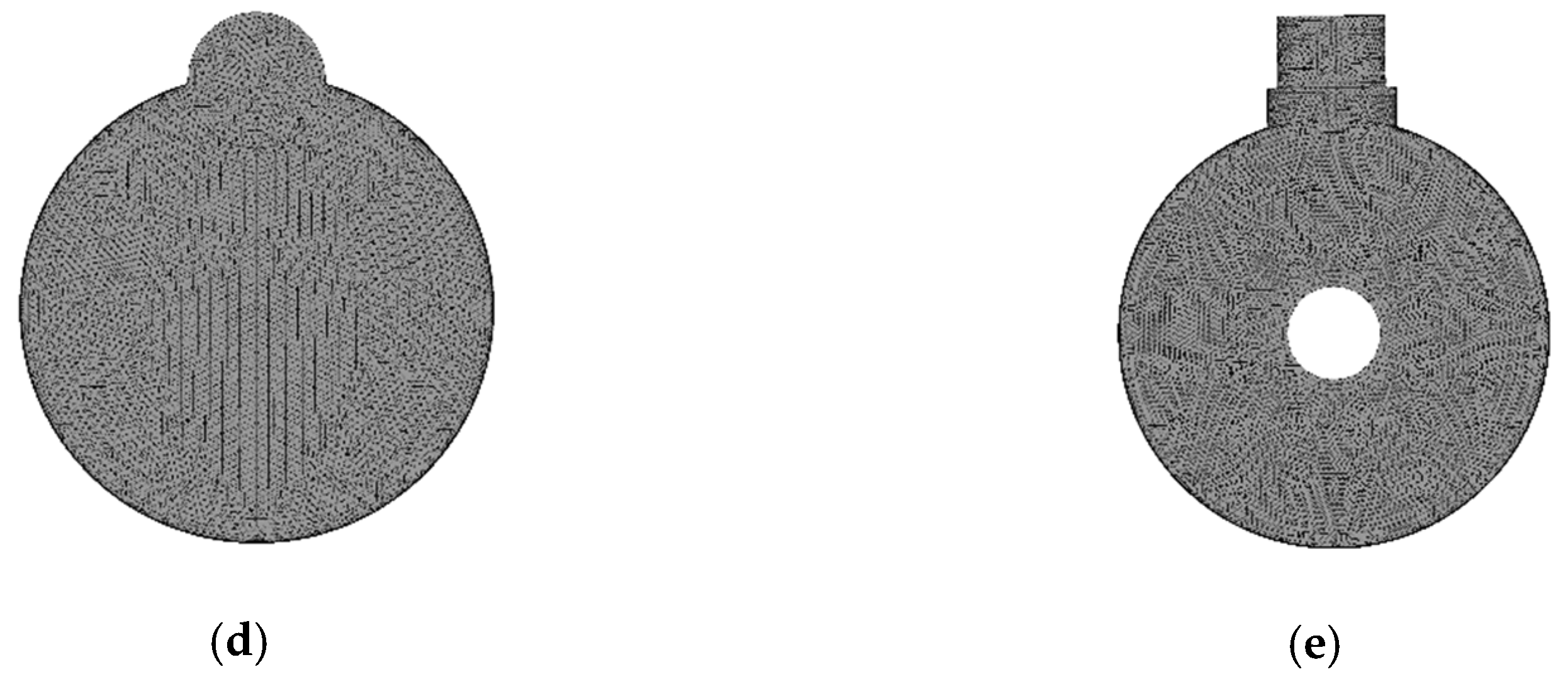
The calculation domain should be discretized before grid-based simulation, and grid quality affects calculation accuracy and time. Generally, dividing a calculation model with a complex geometry and boundary by using hybrid grids is reasonable. The calculation domain was divided into hybrid grids by Gambit software in this study because the numerical model of the self-priming pump and the boundary conditions of the self-priming calculation were complex. Given that performing a grid-independence analysis for the unsteady self-priming calculation is inconvenient due to the large amount of calculation time, the number of grids was made as large as possible but still within the computing capability of the workstation. The main grid information is shown in Figure 4 and Table 2, and the total number of grids is more than four million.

2.4. Time Step Independence

In general, in the periodic numerical simulation, the time step needs to satisfy the Courant number criterion [30], which is expressed as:
Co = vt/l < 100
In the formula, v is the absolute value of the estimated mean velocity, m/s; l is the smallest size of the grid, m; △t is the time step, s; Co is the Courant number criterion and required no more than 100. When the numerical convergence is not good, it is appropriate to take smaller values.
If the time step size is too large, the value of Courant number will also be large; however, too small a time step will also lead to a significant increase in computing time [31,32]. Therefore, considering the computer configuration, the time step △t was chosen as 5 × 10⁻³ s. Moreover, the value of v is within 10 m/s, and the value of l is more than 5 × 10⁻³ m (according to Table 1); therefore the value of Courant number is within 10.

2.5. Setting of the Boundary Condition

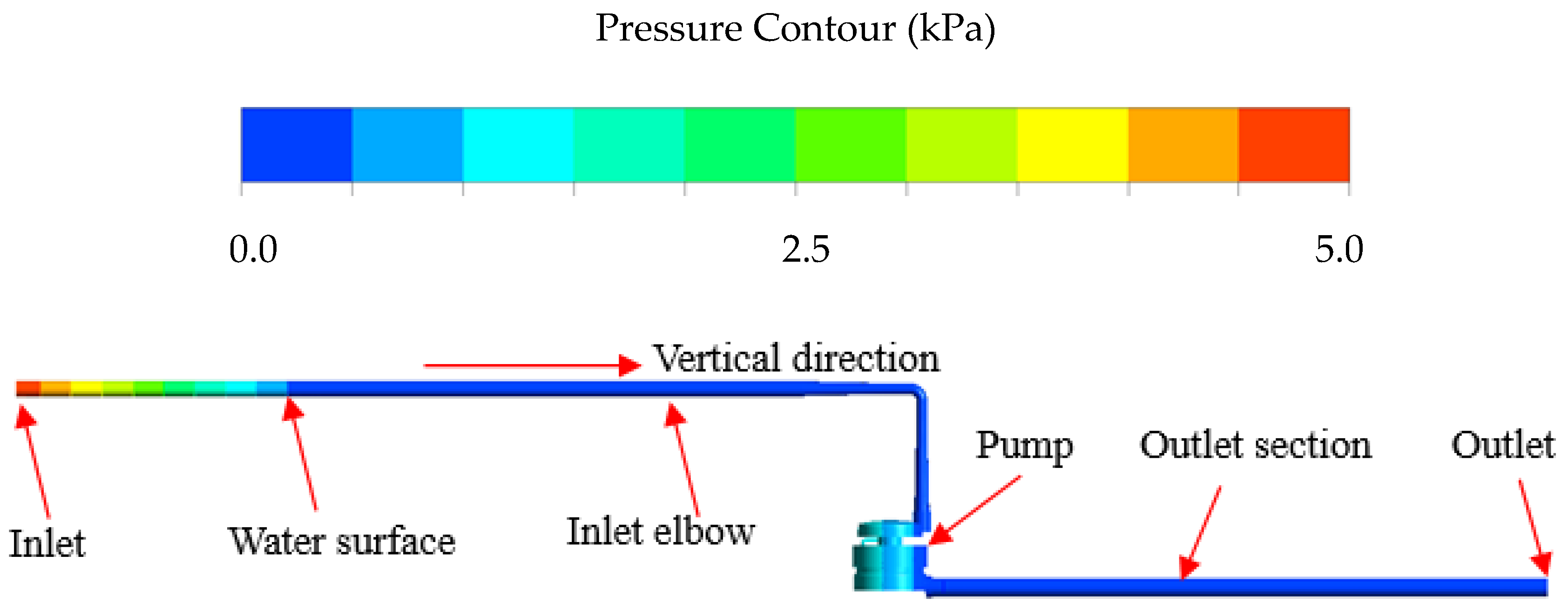
ANSYS Computational Fluid X software (ANSYS CFX 14.5, ANSYS Corporation, Pittsburgh, PA, USA) was used to perform numerical calculation in the self-priming process of the self-priming centrifugal pump. The impeller and shroud in the pump cavity were based on the rotating reference frame, whereas the other sub-domains were based on the stationary reference frame. Moreover, the pressure inlet and the opening in the outlet were selected as inlet and outlet boundaries in order to approximate the actual self-priming condition as much as possible. The gas-water volume fraction contour of the multistage self-priming pump in the initial state is shown in Figure 5. The height of the inlet elbow was 1.5 m, and the height of the outlet pipe was 1 m. The inlet elbow was placed in the water. The elbow above the water surface was filled with gas (1 m in height), the elbow below the water surface was filled with water (0.5 m in height), and the outlet pipe was filled with gas (1 m in height). A check valve was installed in the pump inlet, and the entire pump was also filled with water. Given that the length of the inlet elbow below the water surface was 0.5 m, the initial pressure at the inlet was set to 5 kPa (gage pressure), and the pressure was reduced progressively to 0 kPa until at the water surface. The initial pressure at the inlet and outlet gas sections was 0 kPa. The initial pressure distribution of the entire self-priming pump is shown in Figure 6.

3. Results and Discussion

3.1. Gas-Water Two-Phase Distribution in the Inlet and Outlet Sections of the Pump

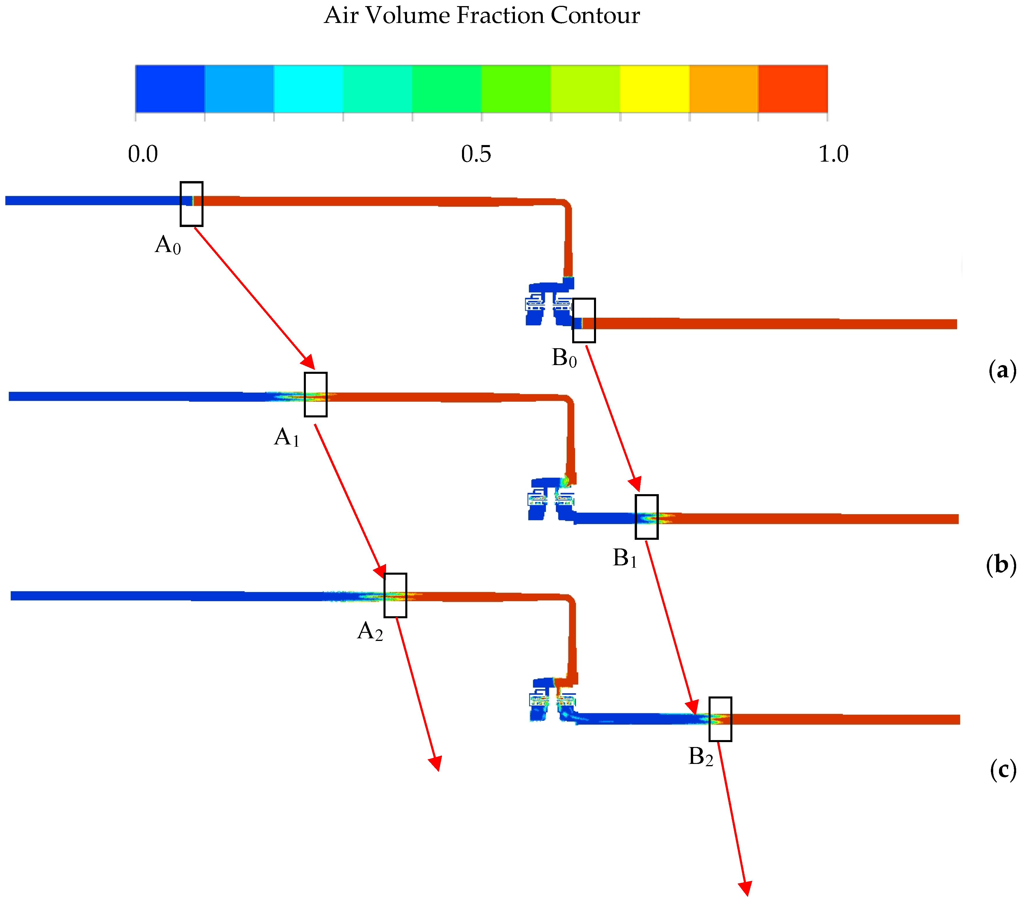
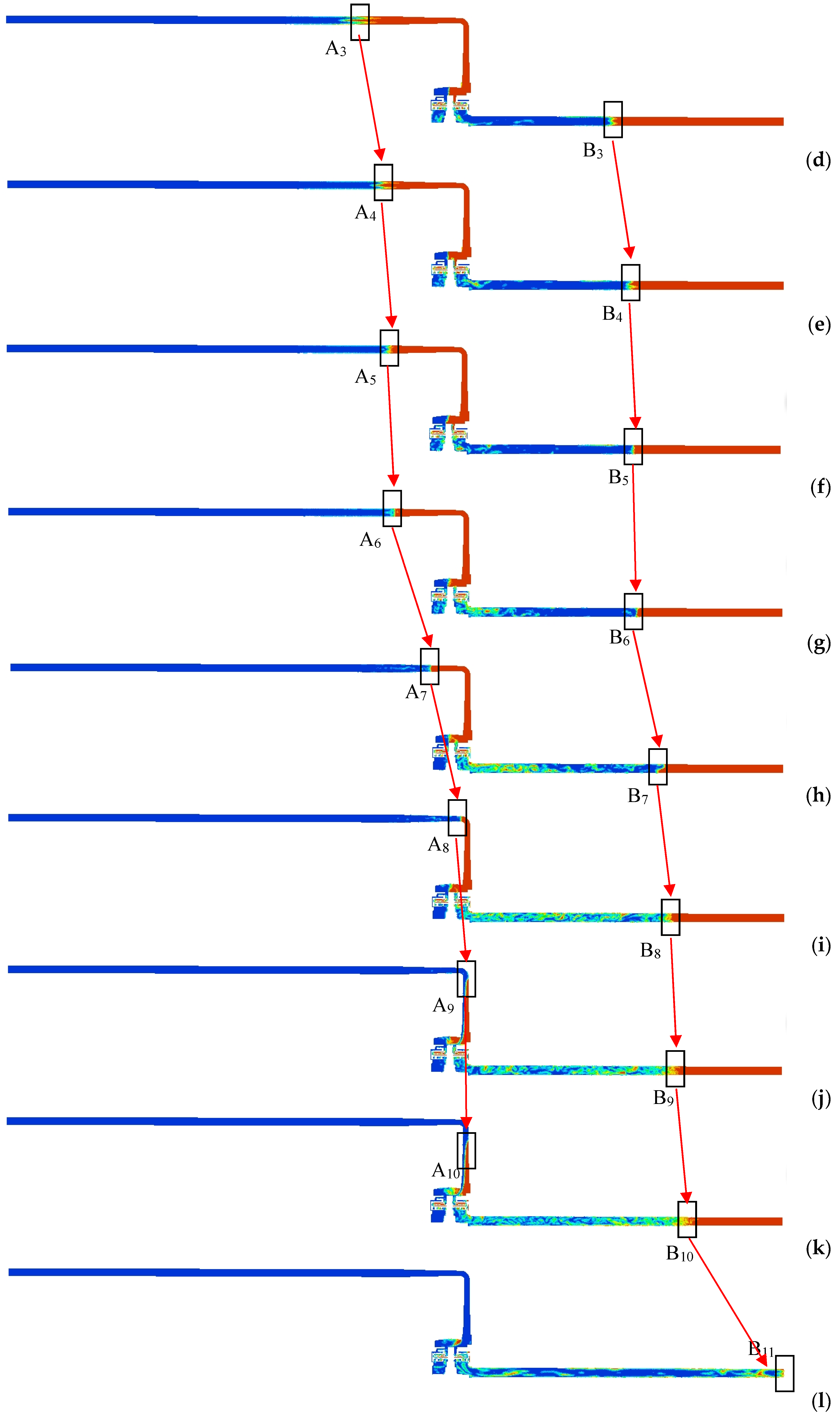
Figure 7 presents the gas-water two-phase distribution in the inlet and outlet sections of the pump at several moments of the entire self-priming process based on CFD. The red area represents gas, and the blue area represents water. a–f show the gas-water two-phase distribution at t = 0, 0.1, 0.2, 0.3, 0.4 and 0.5 s after the start of the pump. Due to the rotation of the impeller, the water in the pump flows rapidly to the outlet section, and the gas in the inlet section rapidly rushes to the pump, and the water column in the inlet and outlet sections rises continuously. Since the void fraction of the impeller is getting larger and larger, the work capacity of the impeller is gradually weakened, resulting in a slower rise in the water column in the inlet and outlet sections (see A0 to A5 and B0 to B5). At t = 0.5 s, the height of the water column in the inlet and outlet sections remains essentially constant (see A4 to A5 and B4 to B5). At this time, the self-priming process due to the impeller rotational role is substantially complete. Moreover, the gas in the inlet section begins to enter into the outlet section at t = 0.2 s.
Figure 7g–j show the gas-water two-phase distribution at t = 1, 2, 3, 4 s after the self-priming pump is started. It can be seen that the water column in the inlet section is rising and close to the gas-water mixture cavity (see A7 to A10). That’s because some gas-water mixture in the gas-water mixture cavity enters into the gas-water separation cavity successively through the impeller and diffuser. In the gas-water separation cavity, the gas-water mixture is in a free-projecting state. Under the action of buoyancy, the lighter gas flows upwardly into the outlet section, and the heavier water flows downward, and flows back to the impeller inlet through the backflow channel for the next cycle. Repeatedly, the total amount of gas in the pump body steadily decreases, and the gas in the inlet section is continuously replenished to the inside of the pump, thereby causing the water column in the inlet section to continuously rise. Compared to the previous self-priming process, the rising rate of the water column in the current self-priming process is significantly smaller, mainly because the maximum self-priming rate in the previous self-priming process is approximately equal to the pump’s internal maximum flow rate, while the gas and the water are repeatedly mixed and separated, and the gas is exhausted a little bit in the current self-priming process. When 0.5 s < t ≤ 2 s, the gas in the pump has not completely escaped from the water column in the outlet section. As the gas in the water column increases, the water column rises continuously (see B5 to B7). When 2 s < t ≤ 4, the gas escapes from the water column of the outlet section. The current self-priming process is a gas-suction stage due to the role of gas-water mixture and gas-water separation.
Figure 7k–m shows the gas-water two-phase distribution at t = 5, 6, 7 s. It can be seen that the water column in the inlet section rises continuously and enters the pump at t > 4 s, so the impeller void fraction decreases continuously and the work capacity of the impeller is enhanced, leading to a continuous rise in the water column in the outlet sections (see B9 to B11). Compared with the previous self-priming process, the exhaustion rate of the gas in the current self-priming process is significantly larger and most of the gas in the pump is exhausted in a short time. Finally, the entire self-priming process ends and the self-priming centrifugal pump enters the normal working condition.

3.2. Streamline and Gas–Water Two-Phase Distribution in the Middle Section of the Pump

From the previous analysis, it can be found that the whole self-priming process of the self-priming pump is divided into three stages: the gas-suction stage due to the impeller’s rotating role in the initial self-priming stage, gas-suction stage due to gas-water mixing and the role of gas–water separation in the middle self-priming stage, and gas-suction stage due to the water flowing from the inlet elbow into the pump in the final self-priming stage.
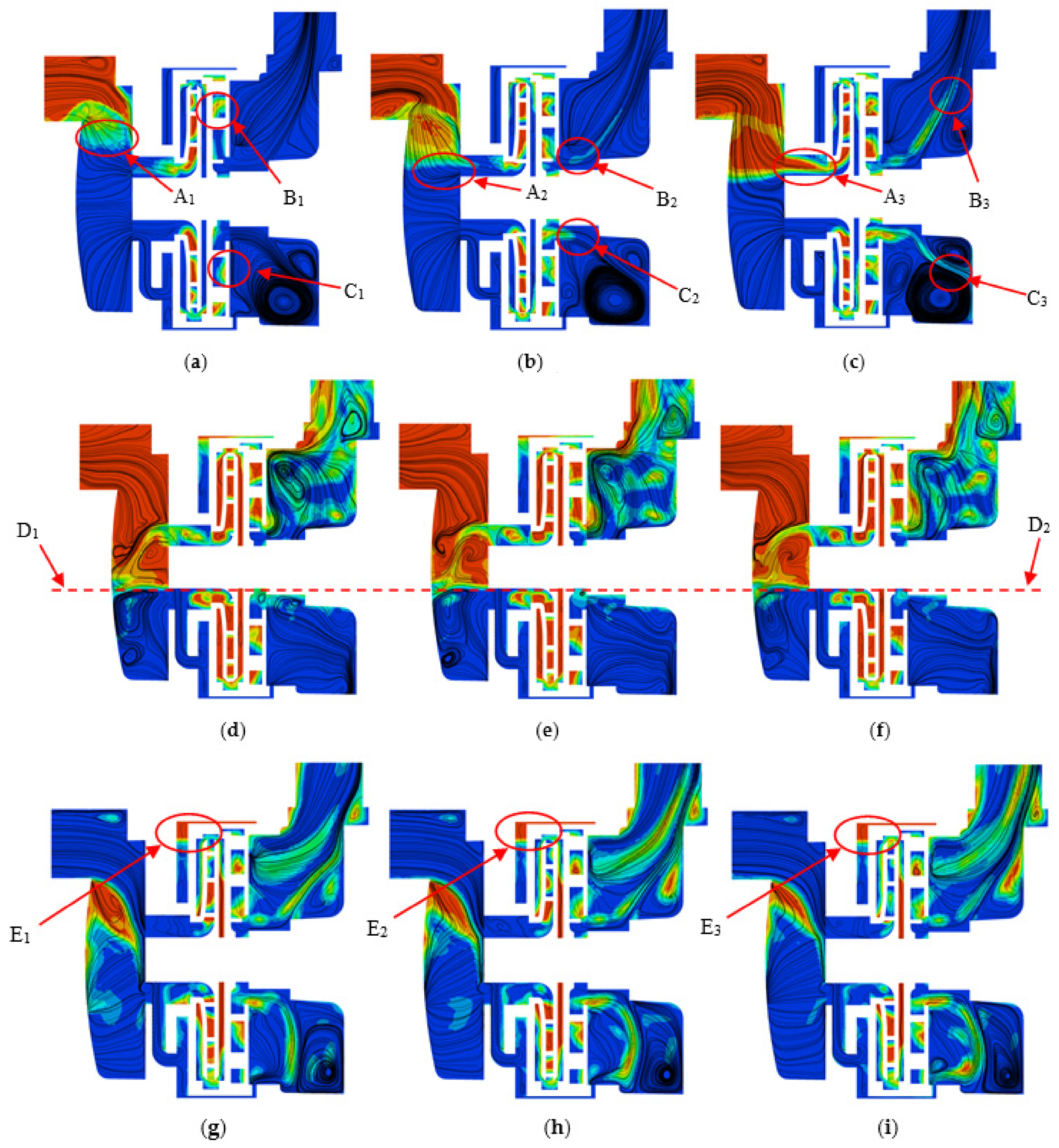
In order to comprehensively study the gas-liquid flow of the pump in the self-priming process, the middle section of the entire pump that best reflects the flow characteristics was selected. Figure 8 shows the streamline and gas-water two-phase distribution in the middle section of the pump at several moments of the self-priming process. The following three self-priming stages of the multistage self-priming pump were obtained through numerical calculation: initial (t ≤ 1 s), middle (1 s < t < 5 s), and final (t ≥ 5 s) self-priming stages. Three moments were selected for analysis for each self-priming process. As shown in Figure 8a,b, the time that the impeller rotates for a cycle is about 0.02 s, and the rotating impeller worked on the water to make it flow quickly to the outlet pipe in the initial self-priming process. Hence, the gas in the inlet section entered the gas-water mixture cavity, mixed with the water, then continuously flowed through the impeller and diffuser (A1, A2, A3). The upper part of the gas-water mixture from the diffuser flowed to the outlet pipe (B1, B2, B3), and the lower part flowed to the lower side of the gas-water separation cavity (C1, C2, C3).
Figure 8d–f shows the streamline and gas-water two-phase distribution in the middle section of the pump at t = 2, 2.02 and 2.04 s. It can be seen that compared with the initial self-priming stage, the change of gas-water two-phase distribution in the middle self-priming is slow, and the gas-water two-phase boundary line in the pump is based on the uppermost end of the lower half of the impeller (D1–D2). The upper half part is mainly the gas phase, and the lower part is mainly the water phase, mainly because the amount of water flowing out from the impeller is basically the same as that from the backflow channel into the impeller, and the amount of exhausting gas is basically the same as the amount of inhaling gas, resulting in that the gas-water two-phase boundary is basically stable. Figure 8g,i indicate that in the final self-priming stage, the entire pump was mainly full of water. A large amount of gas was exhausted from the pump within a short period. In addition, since the backflow channel is only in communication with the lower half of the self-priming cover, a small portion of the gas is sealed in the upper half of the backflow channel and a large resting bubble region is formed (E1, E2, E3). The gas is finally exhausted and even a small amount of gas is not exhausted.

3.3. Vector and Pressure Distribution in the Middle Section of the Backflow Channel

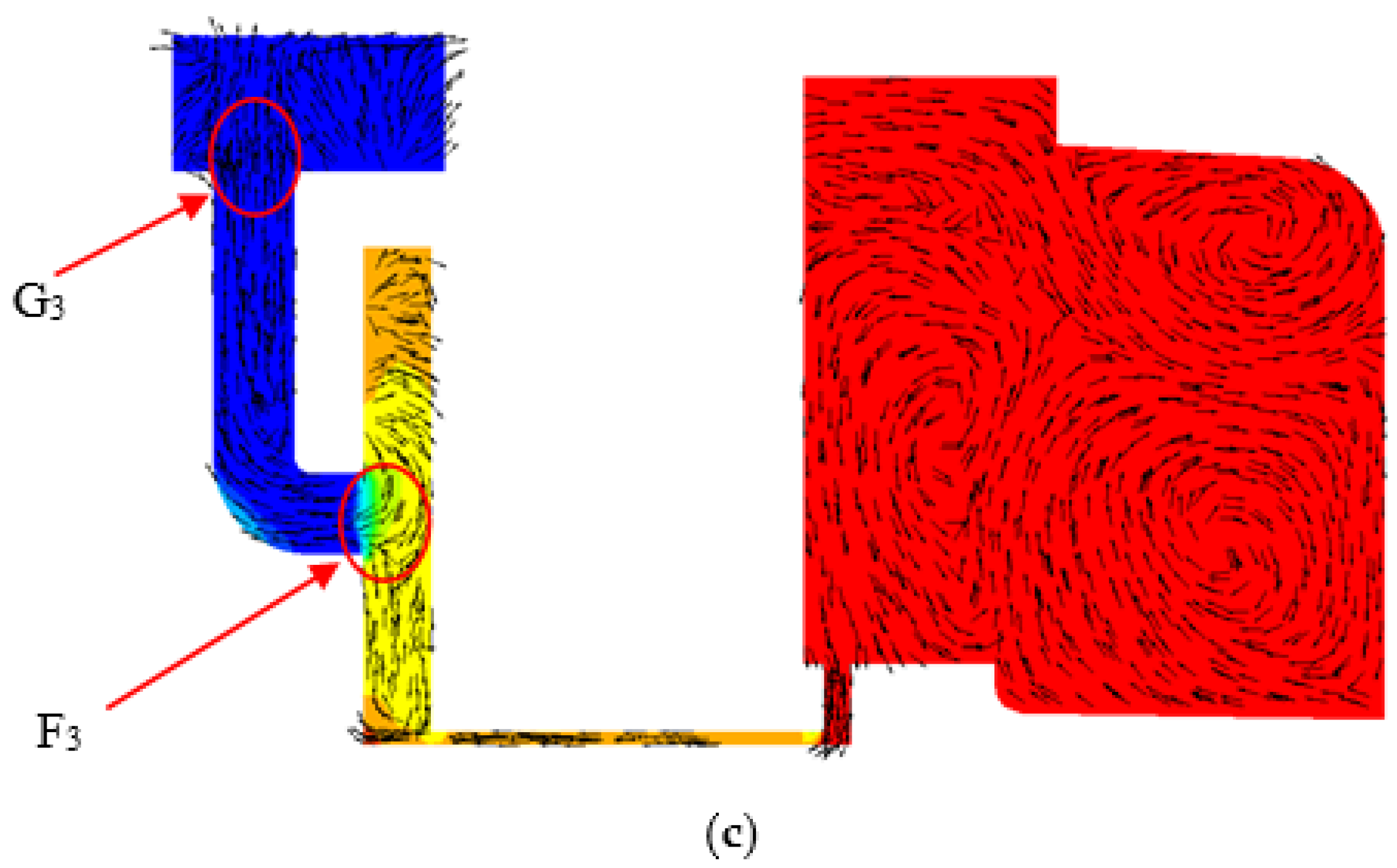
The backflow channel is a key component for water circulation in the self-priming pump. Figure 9 presents the vector and pressure distribution in the middle section of the pump in the three self-priming stages at t = 0.2, 2, and 6 s. It can be seen that due to the work of the rotating impeller, the pressure on the right side of the backflow channel is higher than the left side (B1 and F1), so that the water in the gas-water separation cavity can flow back to the impeller inlet through the backflow channel. In the initial self-priming stage (t = 0.2 s), the gas-water mixture flowing out of the diffuser enters the lower part of the gas-liquid separation cavity (A1). The gas-water mixture presents three flow states. Firstly, the water in the gas-water mixture flows to the backflow hole by gravity (B1). Secondly, the gas in the water in the gas-water mixture flow freely (C1). Thirdly, because the backflow hole is located on the left side of the gas-liquid separation cavity and the backflow capacity of the backflow channel is limited, resulting in a large vortex region on the right side (D1). In the middle self-priming stage (t = 2 s), the flow region of the whole gas-liquid separation cavity is divided into two parts (E1–E2). In the lower region, the water flows down to the backflow hole, while in the upper region, the gas flows upward to the pump outlet. In the final self-priming stage (t = 6 s), the pressure difference between the two sides of the backflow channel increases.
In the initial self-priming stage, the water flowing back from the backflow channel is diverted at the intersection of the self-priming cover (F1). Some water flows to the impeller inlet (G1) and the remainder flows to the upper side of the self-priming cover. In the middle and final self-priming stages, as the water column in the inlet section rises and the pressure at the impeller inlet decreases (G1, G2, G3), the pressure difference between point F and point G rises continuously. The water flowing back from the backflow channel merges with the water on the upper side of the self-priming cover at point F, and flows to the inlet of the impeller. The above results show fully that the backflow capacity of the self-priming pump is gradually enhanced in the three self-priming stages.

3.4. Streamline and Gas-Water Two-Phase Distribution in the Middle Section of the Impeller and Diffuser

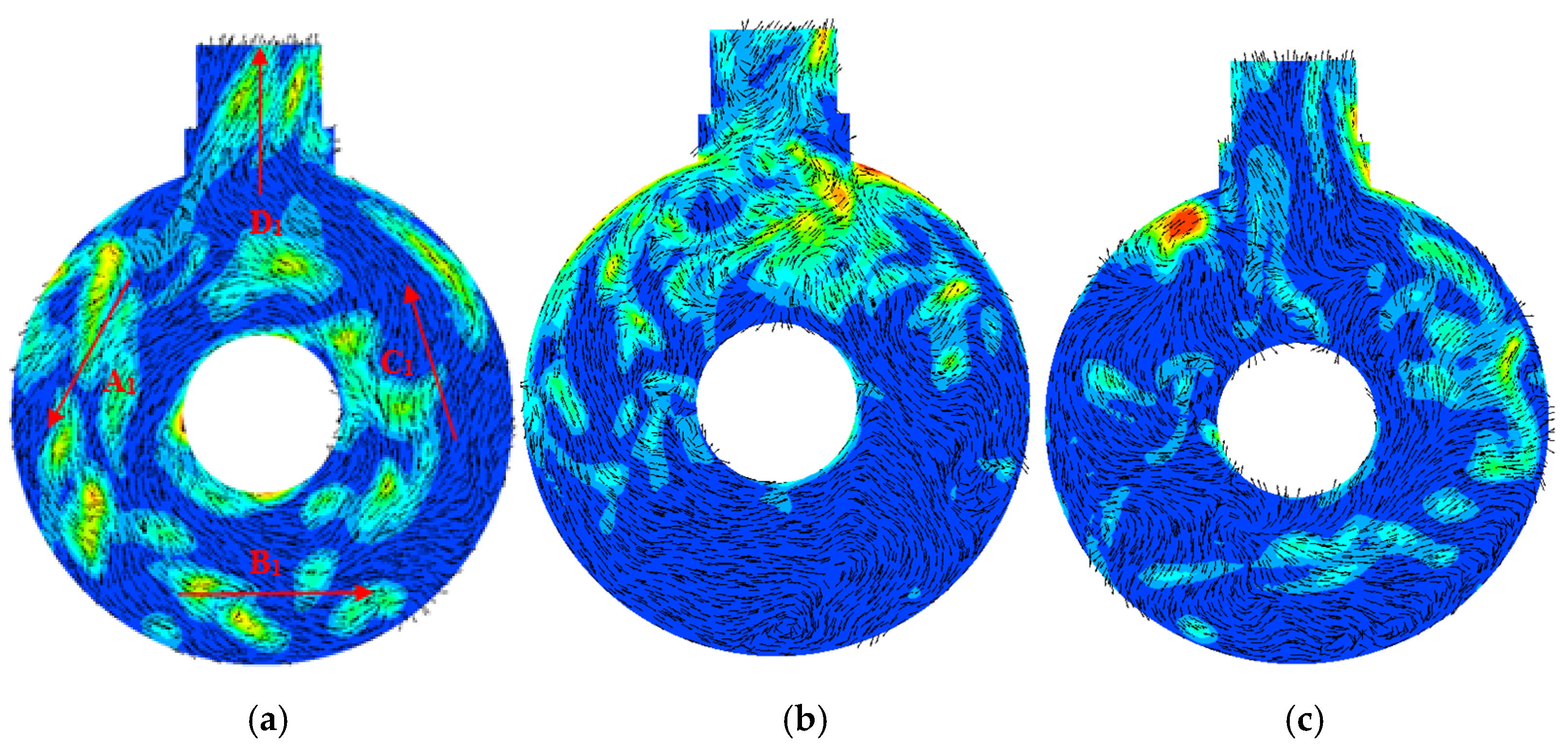
The impeller and diffuser are the core components of the pump. A radial diffuser with outward and return vanes was used, and the middle section of the impeller coincided with the middle section of the outward diffuser. Figure 10 presents the streamline and gas–water two-phase distribution in the middle section of the impeller and outward diffuser in the three self-priming stages. As shown in Figure 10a,b, the void fraction of the impeller and outward diffuser increased rapidly in the initial self-priming stage. When t = 0.2 s, most of the space of the first-stage impeller was filled with gas. That is, only a small amount of gas–water mixture was present at the inlet and pressure surface of the impeller blade (A1 and B1), whereas plenty of gas existed near the suction surface of the impeller that had a large number of vortices, similar to a type of “dead water zone” (D1). The gas-water mixture from the impeller inlet flowed along the pressure surface to the impeller outlet. Upon entering the outward diffuser, the velocity of the gas–water mixture decreased, so more water existed at the impeller outlet and outward diffuser (C1). When t = 0.4 s, the void fraction of the impeller and outward diffuser is further reduced, and the region containing the gas-water mixture at the inlet and pressure surface of the impeller blade is significantly decreased (A1 and A2). As shown in Figure 10c,d, in the middle self-priming stage, most of the space in the impeller was filled with gas, and a small amount of water was present at the inlet and pressure side of the impeller blade. Eventually, the exhausting and inhaling rates gradually reached a state of dynamic equilibrium, and the void fraction of the impeller and outward diffuser is basically stable. Compared with the initial self-priming stage, and the vortex region in the impeller is slightly reduced in the middle self-priming stage (D1 and D2). As shown in Figure 10f,g, the water in the inlet section has begun to enter the impeller in the final self-priming stage, and the void fraction of the impeller is drastically reduced. When t = 6 s, the impeller is basically filled with water; however, there is still some gas in some flow channels of the impeller, indicating that the exhausting process of the impeller has unsteady characteristics. In summary, the key to the self-priming of the pump is that the rotating impeller forces a small amount of gas-water mixture at the impeller inlet to flow along the blade pressure surface to the impeller outlet and into the outward diffuser.
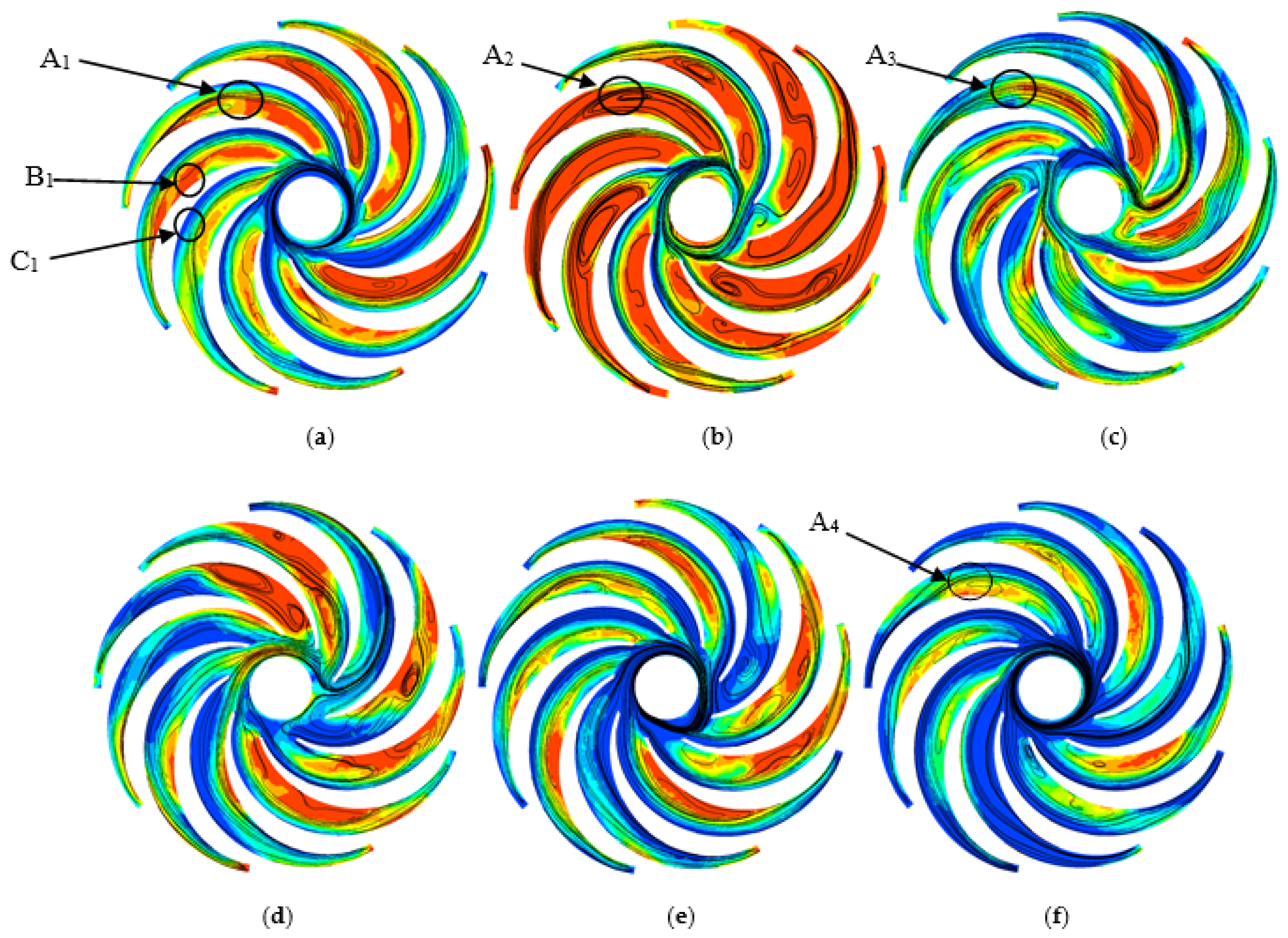
The return diffuser is an important component of the diffuser. It not only introduces the liquid into the outlet section, but also eliminates the rotational component of the liquid. Figure 11 presents the flow line and gas-water two-phase distribution in the middle section of the return diffuser in the three self-priming stages. As shown in Figure 11a,b the void fraction of the return diffuser increases sharply (A1 and A2) in the initial self-priming stage, and the return diffuser is substantially filled with gas at t = 0.4 s, and there are many vortices in the gas region. As can be seen from Figure 11c,d, compared with the initial self-priming stage, the void fraction of the return diffuser is decreased (A3). As shown in Figure 11e,f, a large amount of water enters the return diffuser in the final self-priming stage, and the void fraction of the return diffuser is further decreased (A4). In general, the streamline and gas-water mixture in the return diffuser do not evenly distributed along the circumference. The gas first gathers in the region close to the suction surface of the return diffuser (B1), while the water first gathers near the pressure surface (see C1), and the gas-liquid mixture from the outward diffuser flows along the pressure surface of the return diffuser, which is consistent with the gas-water two-phase distribution in the impeller.

3.5. Vector and Gas-Water Two-Phase Distribution in the Middle Section of the Gas-Water Mixture and Separation Cavities

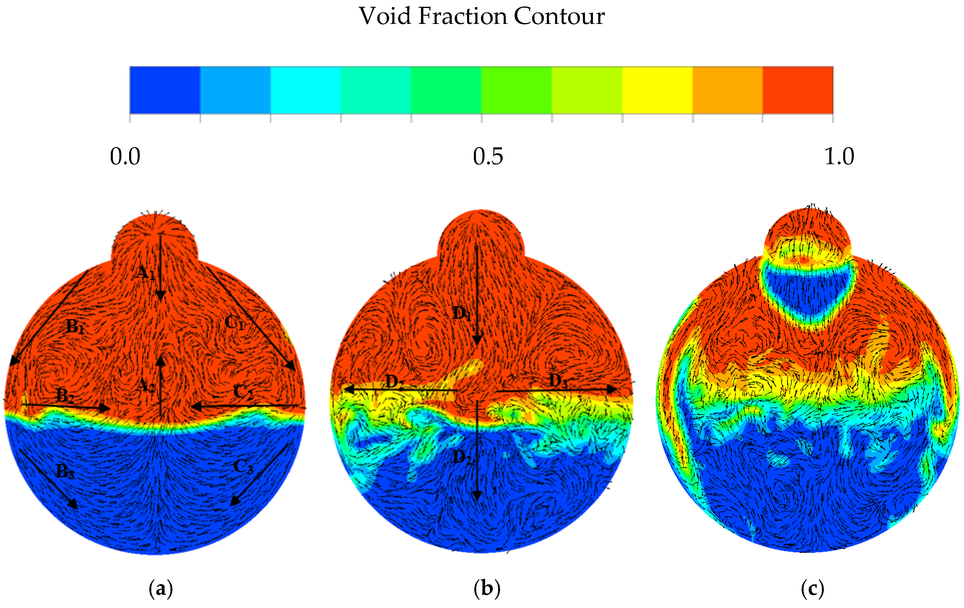
As an important part of the self-priming pump, the gas-water mixture cavity mainly provides space to promote the mixing of gas and water. Figure 12 shows the vector and gas-water two-phase distribution of the gas-water mixture cavity in the self-priming process. As shown in Figure 12a, there is a clear boundary layer in the gas-water mixture cavity in the initial self-priming stage, and the gas is in the upper layer, while the water is in the lower layer. Moreover, when t = 0.4 s, a large amount of gas from the inlet section enter the gas-water mixture cavity and flows downward in three directions (A1, B1 and C1). The gas in the middle direction flows directly downward, the gas in the left and right directions flows down the wall of the gas-liquid mixture cavity, and some of the gas flows back along the boundary layer to the middle portion of the gas-water mixture cavity (B2 and C2), and finally merges with the inflowing gas in the middle direction (A2), and the other gas is mixed with water at the boundary layer to enter the water region (B3 and C3). As can be seen from Figure 12b, the gas-water boundary layer becomes unclear in the middle self-priming stage. The gas from the inlet section enter the gas-water mixture cavity in the middle direction (D1), one part is mixed with water at the boundary layer to enter the water region (D2), and the other part is refluxed in the left and right direction (D3 and D4), forming a large number of vortices. Since the inhaling rate of the gas in the middle self-priming stage is much smaller than that in the initial stage, three parts of gas are combined in the middle of the gas-water mixture cavity in the initial self-priming stage, while a strand of gas is divided into three parts in the middle self-priming stage. As shown in Figure 12c, the gas-water boundary layer has disappeared in the final self-priming stage. Compared with the water region, the flow field in the gas region is more disordered, indicating that the vortex is more likely to be generated in the gas region.
The gas-water separation cavity mainly provides space to promote the separation of gas-water mixture. Figure 13 illustrates the vector and gas-water two-phase distribution of the gas-water separation cavity in the self-priming process. As shown in Figure 13a, the void fraction of the gas-water separation cavity is not high overall and exhibits a non-uniform distribution in the initial self-priming stage. Under the influence of the rotation of the impeller, the gas-water mixture rotates counterclockwise in the annular cavity and escapes from the separation cavity, which is consistent with the rotating direction of the impeller (A1, B1, C1 and D1). As can be seen from Figure 13b, the gas-liquid separation cavity plays the role of the separation of gas and water in the middle self-priming stage. The gas is basically distributed in the upper half of the gas-water separation cavity due to the influence of gravity. Although the internal flow field of the entire gas-water separation cavity is disordered, the flow direction of the annular cavity is counterclockwise. As shown in Figure 13c, since the water from the inlet section starts to enter the pump, a large amount of gas-water mixture flows in the gas-water separation cavity, which not only causes a decrease in the void fraction, but also causes the gas to spread throughout the gas-water separation cavity.

3.6. Data Analysis of the Self-Priming Pump Based on CFD

In the self-priming process of a self-priming centrifugal pump, the gas in the section is exhausted to the outlet pipe through the operation of the pump. In Figure 14, the inlet surface of the inlet section is defined as “In”; the inlet surface of the gas-liquid mixing cavity is defined as “In2” and the outlet surface of the gas-liquid separation cavity is defined as “Out2”. The outlet surface of the outlet pipe is defined as “Out”. In order to illustrate the self-priming capability of the pump, the gas volume coefficient, gas flow coefficient, water flow coefficient, impeller void fraction, and diffuser void fraction are defined in Formulae (2) to (4), respectively.
CV = Vg/Vgt,
C = Qg/Qd
C’ = Qw/Qd
where CV is the gas volume coefficient in the pump; Vg is the sum of the internal gas volume of the pump’s components, except for the outlet pipe, in m3; Vg is the gas volume in the pump in the initial state, which is equal to the gas volume in the inlet section, in m3; C is the gas flow coefficient in the pump; C’ is the water flow coefficient in the pump; Qg is the gas flow in the self-priming process in m3/h; Qw is the water flow in the self-priming process in m3/h; Qd is the water flow at the rated condition after the pump operates normally in m3/h.
Figure 15 shows the gas volume coefficient CV and the gas flow coefficient Cout2 on the “Out2” surface during the self-priming process. A negative gas flow coefficient means that the gas flows out of the pump, whereas a positive one indicates that the gas flows into the pump. In accordance with the previous analysis, the self-priming process of the pump was divided into three stages as follows: initial (t ≤ 0.5 s), middle (0.5 s < t < 4 s), and final (4 s ≤ t). These self-priming stages are shown as I, II, and III in Figure 14. When 0 s < t ≤ 0.15 s, the amplitude of Cout2 was close to 0, and the value of CV remained 1, indicating that the gas in the inlet section began to reach the “Out2” surface at t = 0.15 s. When t > 0.15 s, the distribution of Cout2 showed a serious fluctuation, which shows the unsteady characteristics of the self-priming process of the pump. When 0.15 s < t ≤ 0.5 s, the amplitude of Cout2 increased initially then decreased; afterward, it reached the maximum of 0.15. When 0.5 s < t ≤ 4 s, it decreased and reached the minimum of 0.02. When 4 s < t ≤ 5.8 s, it increases again, reaching the maximum of 0.56. When 5.8 s < t ≤ 8 s, it decreases again and finally approached 0, indicating that the gas in the pump was basically exhausted. In the entire self-priming process, the value of CV continuously decreased, and the decrement rate was affected by Cout2.
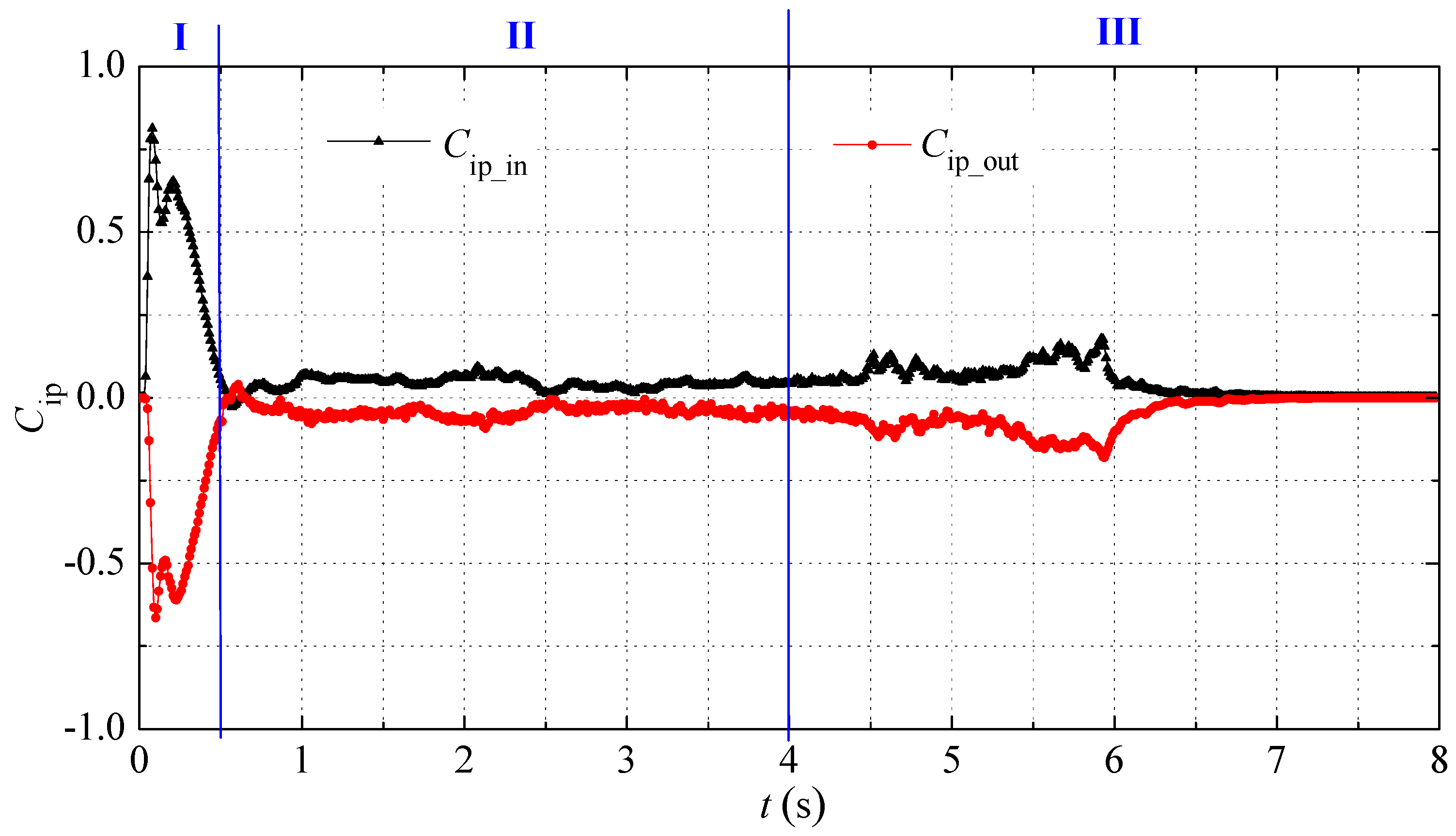
The impeller and diffuser are the core components of the self-priming pump. Figure 16 displays the gas flow coefficient Cip_in and Cip_out of impeller inlet and outlet in the self-priming process. When 0 s < t ≤ 0.05 s, the value of Cip_in increased from 0 to 0.8, while that of Cip_out increased from 0 to 0.65, indicating that part of the gas remained in the impeller. When 0.08 s < t ≤ 0.5 s, the working capacity of the impeller was weakened due to the increase of the impeller void fraction in the initial self-priming stage, and the amplitudes of Cip_in and Cip_out decreased and approached 0, showing a certain positive correlation between them. When 0.5 s < t ≤ 4 s, the amplitudes of Cip_in and Cip_out fluctuated continuously but increased first and then decreased on the whole. The reason for the increment was that the amplitudes of Cip_in and Cip_out were close to 0 at t = 0.5 s, while the reason for the decrement was that the lower the pressure at the impeller inlet, the slower the rising rate of the water column in the inlet section, and the slower the suction rate of the impeller. When t > 4 s, the water in the inlet section flowed into the impeller in the final self-priming stage, causing the drainage capacity of the impeller to increase sharply. The amplitudes of Cip_in and Cip_out continued to increase, and the maximum value was close to 0.2. Then, as the total amount of gas in the pump decreased, the amplitudes of Cip_in and Cip_out continued to decrease, and finally close to 0.
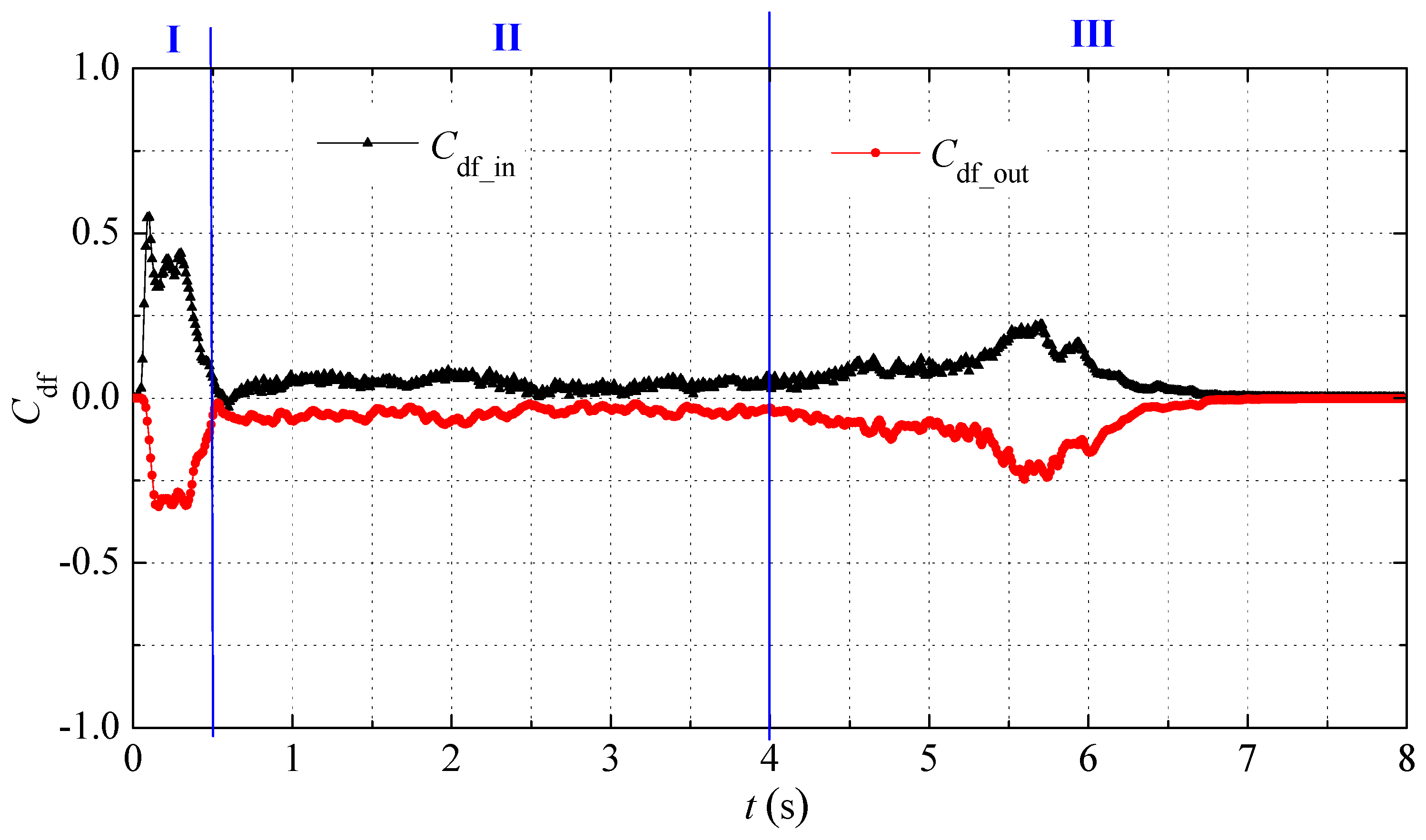
Figure 17 shows the gas flow coefficient Cdf_in and Cdf_out of the diffuser inlet and outlet in the self-priming process. It can be seen that the changing law of Cdf_in and Cdf_out was basically the same as that of Cip_in and Cip_out. In the initial, middle, and final self-priming stages, the value of Cdf_in and Cdf_out first increased and then decreased.
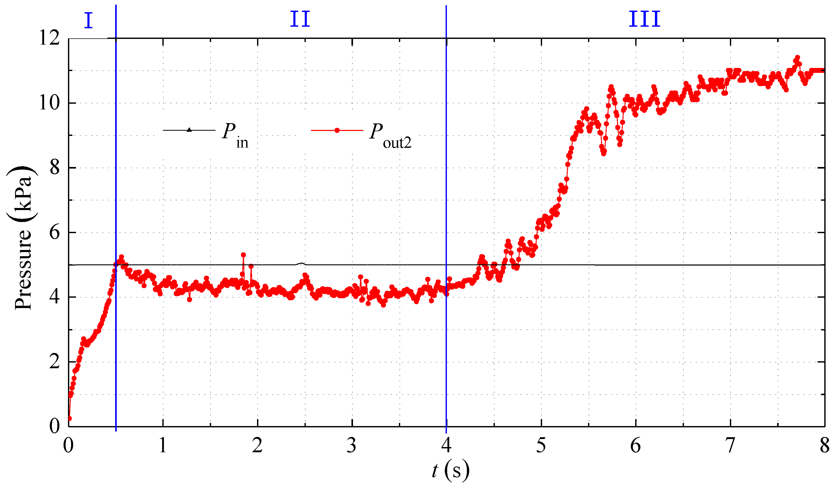
As a standard characteristic parameter of the pump, pressure is one of the important factors affecting the self-priming capability of the self-priming centrifugal pump. Figure 18 presents the pressure Pin on the “In” surface and pressure Pout2 on the “Out2” surface in the self-priming process. It can be seen that the value of Pin was basically kept at 5 kPa, due to that the “In” surface was 0.5 m under water and the pressure value was only affected by atmospheric pressure. In addition, the value of Pout2 was rapidly increased from 0 kPa to 5 kPa in the initial self-priming stage, it remained stable in the middle self-priming stage, and rapidly increased to 10 kPa in the final self-priming stage.
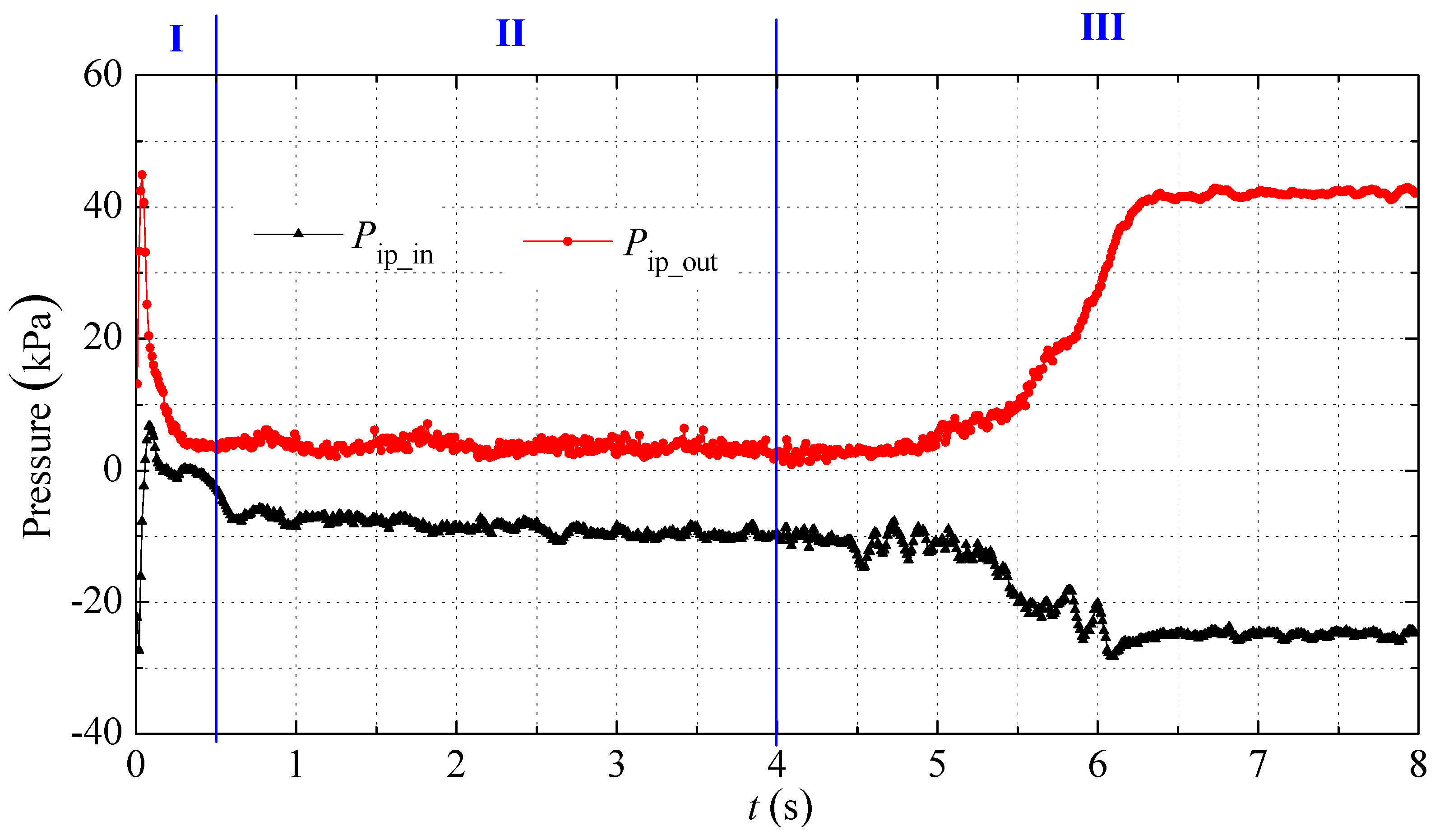
Figure 19 illustrates the pressure Pip_in and Pip_out of the impeller inlet and outlet in the self-priming process. It can be seen that when 0 s < t ≤ 0.05 s, after the impeller filled with water started to rotate, the value of Pip_in rapidly decreased from 0 kPa to −27 kPa and then increased to 7 kPa, while the value of Pip_out increased to 45 kPa. When 0.05 s < t ≤ 0.5 s, with the rapid increase of the impeller void fraction, the working capability of the impeller was sharply weakened, the value of Pip_in and Pip_out decreased to −2.5 kPa and 3.5 kPa, respectively. When 0.5 s < t ≤ 4 s, since the gas in the inlet section was slowly exhausted out of the pump, the water column in the inlet section raised continuously, and the value of Pip_in showed a downward trend, while the value of Pip_out was basically stable. When 4 s < t ≤ 8 s, the value of Pip_in dropped sharply and the value of Pip_out raised significantly due to the sharp decrease of the impeller void fraction. Finally, when the impeller void fraction was close to 0, the value of Pip_in and Pip_out remained at −25 kPa and 42 kPa.
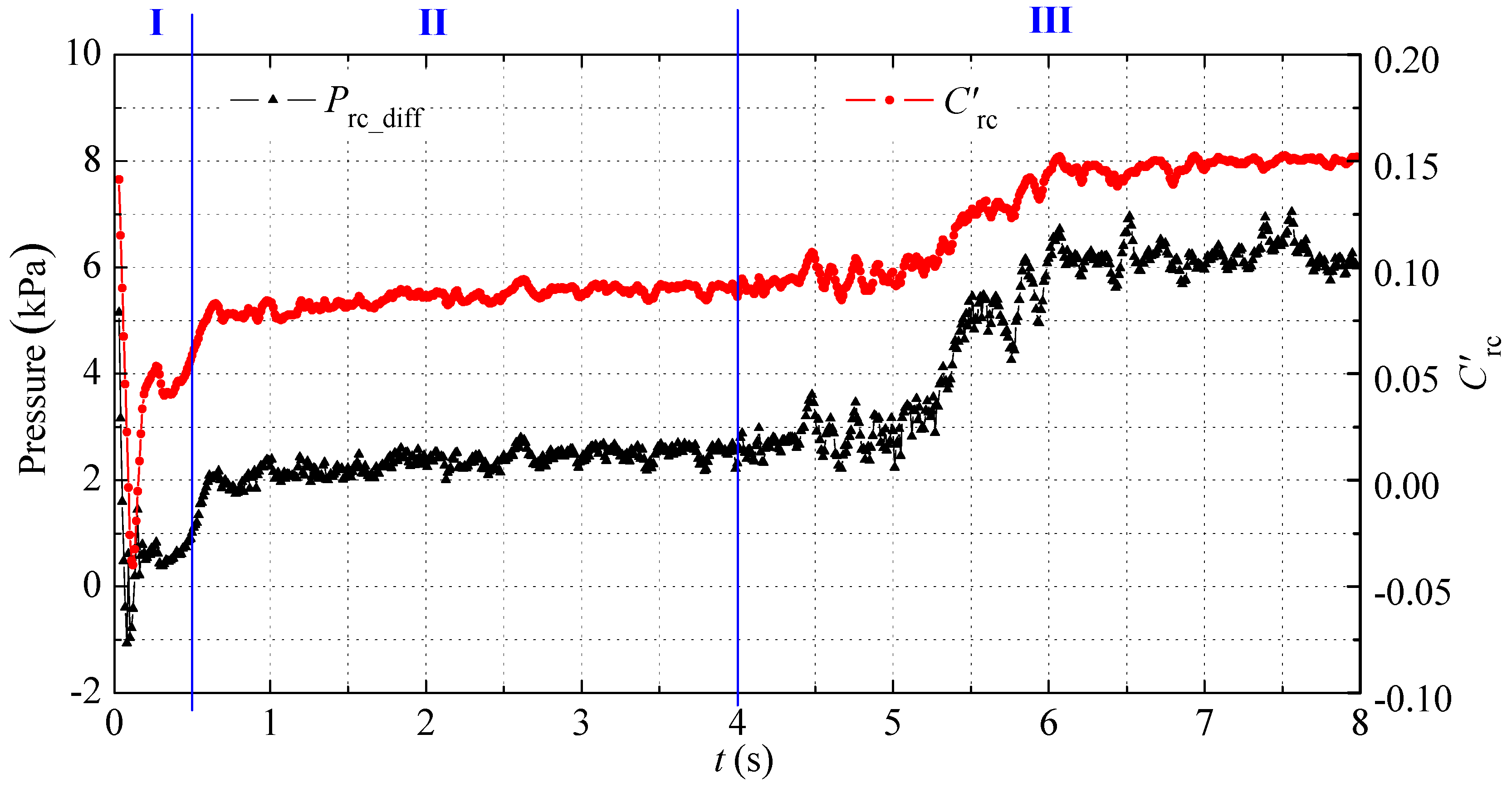
Figure 20 and Figure 21 present the pressure difference between the two ends of backflow channel Pbc and water flow coefficient C’bc in the whole self-priming process and middle self-priming stage. It can be seen that in the initial self-priming stage, the value of Pbc and C’bc reached the maximum rapidly, then decreases rapidly. In the middle self-priming stage, the value of Pbc and C’bc constantly fluctuated. In the final self-priming stage, the values of Pbc and C’bc increased sharply and remained essentially stable. Moreover, the value of C’bc had a positive correlation with Pbc, which was especially evident in the middle self-priming stage, as shown in Figure 20. In the middle self-priming stage of t = 2.65 s, the maximum value of Pbc reached 2.8 kPa, while the maximum value of C’bc was 0.095.
4. Conclusions

(1) The entire self-priming process of the self-priming centrifugal pump can be divided into three stages: gas-suction stage due to the impeller’s rotating role in the initial self-priming stage, gas-suction stage due to the role of gas-water mixture and gas-water separation in the middle self-priming stage, and gas-suction stage due to the water flowing from the inlet section into the pump in the final self-priming stage. Moreover, the self-priming time of the initial and final self-priming stages accounts for a small percentage of the entire self-priming process. The middle self-priming stage is the main stage in the self-priming process and determines the length of self-priming time.
(2) In the initial self-priming stage, the self-priming centrifugal pump is mainly based on drainage, and the gas is mixed with water before going outside the pump; it takes a certain amount of time for the gas to move from the inlet section to the outlet section. With the increase in the void fraction of the impeller, the drainage capacity of the self-priming pump is weakened, and the gas-exhausting rate is fast then slow. After entering the middle self-priming stage, due to the formation of a large negative pressure at the impeller inlet, the decreasing rate of the pressure continues to slow down on this basis, and the gas-suction rate of the self-priming centrifugal pump also slows down. In the final self-priming stage, the water in the inlet section goes into the impeller, whose power capability is enhanced obviously. The water mixed with the gas goes to the outlet section, so the gas-suction rate of the self-priming pump increased and reached the maximum value at a certain time. Afterward, the gas-suction rate decreased and finally approaches 0, due to the fact that the amount of gas in the pump decreases continuously.
(3) In the initial self-priming stage, the region near the suction surface of the impeller blade (low-pressure region) is easily occupied by gas. In the final self-priming stage, the region near the pressure surface of the impeller blade (high-pressure region) is easily occupied by water. In the middle self-priming stage, the impeller void fraction is high and a small amount of gas-water mixture exists in a small region close to the pressure surface of the impeller blade and impeller outlet. The key to successful self-priming is that the impeller’s rotation forces a small amount of water mixed with some gas to flow along the pressure side of the impeller blade from the impeller inlet to the impeller outlet. Then, the mixture goes into the outward diffuser and flows along the pressure surface of the return diffuser, which shows that the gas-water mixture always flows along the high-pressure side of the pump in the self-priming process. The diffuser void fraction varies like the impeller void fraction, but its overall amplitude is lower.
(4) In the whole self-priming process, the backflow function of the backflow channel is the key to self-priming, and the pressure difference at both ends of the backflow channel is the main reason for the backflow function.

Author Contributions

B.H. and Y.Z. conceived and designed the experiments; X.W. performed the experiments; C.L. analyzed the data; C.W. and L.C. wrote the paper.

Acknowledgments

This research was funded by National Natural Science Foundation of China (Grant No.51609105), Jiangsu Province Science Foundation for Youth (Grant No. BK20170507), China Postdoctoral Science Foundation (Grant No.2016M601738 and 2018T110458). And the APC was funded by Priority Academic Program Development of Jiangsu Higher Education Institutions(PAPD).

Conflicts of Interest

The authors declare no conflict of interest.

References

  1. Li, X.; Jiang, Z.; Zhu, Z.; Si, Q.; Li, Y. Entropy generation analysis for the cavitating head-drop characteristic of a centrifugal pump. Proc. Inst. Mech. Eng. Part C: J. Mech. Eng. Sci. 2018, 232, 4637–4646. [Google Scholar] [CrossRef]
  2. Wang, C.; He, X.; Shi, W.; Wang, X.; Qiu, N. Numerical study on pressure fluctuation of a multistage centrifugal pump based on whole flow field. Am. Inst. Phys. Adv. 2019, 9, 035118. [Google Scholar] [CrossRef] [Green Version]
  3. Zhang, S.; Li, X.; Hu, B.; Liu, Y.; Zhu, Z. Numerical investigation of attached cavitating flow in thermo-sensitive fluid with special emphasis on thermal effect and shedding dynamics. Int. J. Hydrogen Energy 2019, 44, 3170–3184. [Google Scholar] [CrossRef]
  4. Wang, C.; Chen, X.; Qiu, N.; Zhu, Y.; Shi, W. Numerical and experimental study on the pressure fluctuation, vibration, and noise of multistage pump with radial diffuser. J. Braz. Soc. Mech. Sci. Eng. 2018, 40, 481. [Google Scholar] [CrossRef]
  5. Li, X.; Gao, P.; Zhu, Z.; Li, Y. Effect of the blade loading distribution on hydrodynamic performance of a centrifugal pump with cylindrical blades. J. Mech. Sci. Technol. 2018, 32, 31161–31170. [Google Scholar] [CrossRef]
  6. Wang, C.; Shi, W.; Wang, X.; Jiang, X.; Yang, Y.; Li, W.; Zhou, L. Optimal design of multistage centrifugal pump based on the combined energy loss model and computational fluid dynamics. Appl. Energy 2017, 187, 10–26. [Google Scholar] [CrossRef]
  7. Gao, R.; Li, Y.; Yu, M.; Liu, W. Effects of heat pump drying parameters on the volatile flavour compounds in silver carp. J. Aquat. Food Prod. Technol. 2016, 735–744. [Google Scholar] [CrossRef]
  8. Xie, F.; Xuan, R.; Sheng, G.; Wang, C. Flow characteristics of accelerating pump in hydraulic-type wind power generation system under different wind speeds. In. J. Adv. Manuf. Technol. 2017, 92, 189–196. [Google Scholar]
  9. Xia, C.; Cheng, L.; Luo, C.; Jiao, W.; Zhang, D. Hydraulic Characteristics and Measurement of Rotating Stall Suppression in a Waterjet Propulsion System. Trans. FAMENA 2018, 4, 85–100. [Google Scholar] [CrossRef]
  10. Qian, J.; Chen, M.; Liu, X.; Jin, Z. A numerical investigation of the flow of nanofluids through a micro Tesla valve. J. Zhejiang Univ. SCIENCE A 2019, 20, 50–60. [Google Scholar] [CrossRef]
  11. Lu, Z.; He, X.; Wang, C. Influencing factors of self-priming time of multistage self-priming centrifugal pump. DYNA 2018, 93, 630–635. [Google Scholar] [CrossRef]
  12. Chang, H.; Shi, W.; Li, W.; Liu, J. Energy loss analysis of novel self-priming pump based on the entropy production theory. J. Therm. Sci. 2018, 28, 1–13. [Google Scholar] [CrossRef]
  13. Wang, C.; He, X.; Zhang, D.; Hu, B. Numerical and experimental study of the self-priming process of a multistage self-priming centrifugal pump. Int. J. Energy Res. 2019, 1–19. [Google Scholar] [CrossRef]
  14. Chang, H.; Li, W.; Shi, W.; Liu, J. Effect of blade profile with different thickness distribution on the pressure characteristics of novel self-priming pump. J. Braz. Soc. Mech. Sci. Eng. 2018, 40, 518. [Google Scholar] [CrossRef]
  15. Qian, J.; Gao, Z.; Liu, B.; Jin, Z. Parametric study on fluid dynamics of pilot-control angle globe valve. ASME J. Fluids Eng. 2018, 140, 111103. [Google Scholar] [CrossRef]
  16. Zhang, J.; Xia, S.; Ye, S.; Xu, B.; Song, W.; Zhu, S.; Xiang, J. Experimental investigation on the noise reduction of an axial piston pump using free-layer damping material treatment. Appl. Acoust. 2018, 139, 1–7. [Google Scholar] [CrossRef]
  17. Zhao, X.; Xu, Y.; Lei, Q. Theoretical and experimental research on characteristics of vertical self-priming centrifugal pump. J. East China Univ. Sci. Technol. 1996, 22, 455–461. [Google Scholar]
  18. Yi, Q. Statistics and exploration on the self-priming time and specific speed of the self-priming pump. Drain. Irrig. Mach. 1992, 4, 8–11. [Google Scholar]
  19. Wang, C.; Wu, Z.; Si, Y.; Yi, T. Gas-liquid two-phase flow numerical simulation of a vortex flow self-priming pump. Drain. Irrig. Mach. 2009, 27, 163–167. [Google Scholar]
  20. Wang, C.; Si, Y.; Zheng, H.; Peng, N.; Zhao, B.; Zhang, H. Numerical simulation of rotational interior flow in self-priming pump. Drain. Irrig. Mach. 2008, 26, 31–35. [Google Scholar]
  21. Liu, J.; Su, Q.; Xu, Y.; Wang, D. Numerical simulation of internal flow field of self-priming irrigation pump. Drain. Irrig. Mach. 2009, 27, 347–351. [Google Scholar]
  22. Liu, J.; Su, Q. Simulation on gas-liquid two-phase flow in self-priming pump. Trans. Chin. Soc. Agric. Mach. 2009, 40, 73–76. [Google Scholar]
  23. Li, H.; Xu, D.; Tu, Q.; Cheng, J. Numerical simulation on gas-liquid two-phase flow of self-priming pump during starting period. Trans. Chin. Soc. Agric. Eng. 2013, 29, 77–83. [Google Scholar]
  24. Lu, T.; Li, H.; Zhan, L. Transient numerical simulation and visualization of self-priming process in self-priming centrifugal pump. J. Drain. Irri. Mach. Eng. 2016, 34, 927–933. [Google Scholar]
  25. Huang, S.; Su, X.; Guo, J.; Yue, Y. Unsteady numerical simulation for gas–liquid two-phase flow in self-priming process of centrifugal pump. Energy Convers. Manag. 2014, 85, 694–700. [Google Scholar] [CrossRef]
  26. Hubbard, B. Self-priming characteristics of flexible impeller pumps. World Pumps 2000, 405, 19–21. [Google Scholar]
  27. Yan, H. Test on the effects of gas-water separation chamber volume of self-priming pump on self-priming performance. Fluid Mach. 1996, 24, 39–40. [Google Scholar]
  28. Zhang, X. Effect of backflow hole on the self-priming pump. Gen. Mach. 2004, 3, 41–46. [Google Scholar]
  29. Chen, M. Design and Test of High-head self-priming centrifugal pump. Fluid Mach. 1998, 26, 7–11. [Google Scholar]
  30. Desbrun, M.; Gascuel, M.P. Smoothed particles: A new paradigm for animating highly deformable bodies. In Computer Animation and Simulation’; Springer: Vienna, Austria, 1996; pp. 61–76. [Google Scholar]
  31. Belytschko, T.; Neal, M.O. Contact-impact by the pinball algorithm with penalty and Lagrangian methods. Int. J. Numer. Methods Eng. 1991, 31, 547–572. [Google Scholar] [CrossRef]
  32. Kim, J.; Moin, P. Application of a fractional-step method to incompressible Navier-Stokes equations. J. Comput. Phys. 1985, 59, 308–323. [Google Scholar] [CrossRef]
Figure 1. Assembly diagram of the self-priming centrifugal pump. 1. Inlet section; 2. Gas-water mixture cavity; 3. Self-priming cover plate; 4. Impeller; 5. Diffuser; 6. Outer casing; 7. Gas-water separation cavity; 8. Outlet section.
Processes 07 00330 g001
Figure 2. Three-dimensional models and practical pictures of the impeller and diffuser. (a) Plane and axial projection of the impeller; (b) Outward and return vane of the diffuser; (c) Practical impeller; (d) Practical diffuser.
Processes 07 00330 g002
Figure 3. Calculation domain of the self-priming centrifugal pump by using Pro/Engineering software (Pro/E 5.0, Parametric Technology Corporation, Boston, MA, USA). 1. Inlet section; 2. Gas-water mixture cavity; 3. Self-priming cover plate; 4. Pump cavity; 5. Impeller; 6. Diffuser; 7. Gas-water separation cavity; 8. Outlet section; 9. Backflow channel.
Processes 07 00330 g003
Figure 4. Grid of the self-priming centrifugal pump by using Gambit software (Gambit 2.4.6, ANSYS Corporation, Pittsburgh, PA, US.). (a) Total pump; (b) Impeller; (c) Diffuser; (d) Gas-water mixture cavity; (e) Gas-water separation cavity.
Processes 07 00330 g004aProcesses 07 00330 g004b
Figure 5. Void fraction contour of the self-priming pump in the initial state.
Processes 07 00330 g005
Figure 6. Static pressure contour of the self-priming pump in the initial state.
Processes 07 00330 g006
Figure 7. Gas–water two-phase distribution in the inlet and outlet sections of the pump at several moments of the entire self-priming process. (a) t = 0 s; (b) t = 0.1 s; (c) t = 0.2 s; (d) t = 0.3 s; (e) t = 0.4 s; (e) t = 0.5 s; (f) t = 1 s; (g) t = 2 s; (h) t = 3 s; (i) t =3 s; (j) t = 4 s; (k) t = 5 s; (l) t = 6 s; (m) t = 7 s.
Processes 07 00330 g007aProcesses 07 00330 g007bProcesses 07 00330 g007c
Figure 8. Streamline and gas–water two-phase distribution in the middle section of the pump at several moments of the self-priming process. (a) t = 0.1 s; (b) t = 0.12 s; (c) t = 0.14 s; (d) t = 2 s; (e) t = 2.02 s; (f) t = 2.04 s; (g) t = 6 s; (h) t = 6.02 s; (i) t = 6.04 s.
Processes 07 00330 g008aProcesses 07 00330 g008b
Figure 9. Vector and pressure distribution of the backflow channel in the self-priming process. (a) t = 0.2 s; (b) t = 2 s; (c) t =6 s.
Processes 07 00330 g009aProcesses 07 00330 g009b
Figure 10. Streamline and gas–water two-phase distribution of the impeller and outward diffuser at several moments of the self-priming process. (a) t = 0.2 s; (b) t = 0.4 s; (c) t = 1 s; (d) t = 2 s; (e) t = 5 s; (f) t = 6 s.
Processes 07 00330 g010aProcesses 07 00330 g010b
Figure 11. Streamline and gas-water two-phase distribution of the return diffuser at several moments of the self-priming process. (a) t = 0.2 s; (b) t = 0.4 s; (c) t = 1 s; (d) t = 2 s; (e) t = 5 s; (f) t = 6 s.
Processes 07 00330 g011aProcesses 07 00330 g011b
Figure 12. Vector and gas-water two-phase distribution of the gas-water mixture cavity in the self-priming process. (a) t = 0.2 s; (b) t = 2 s; (c) t = 5 s.
Processes 07 00330 g012
Figure 13. Vector and gas-water two-phase distribution of the gas-water separation cavity in the self-priming process. (a) t = 0.2 s; (b) t = 2 s; (c) t = 5 s.
Processes 07 00330 g013aProcesses 07 00330 g013b
Figure 14. Definition of several typical surfaces of the self-priming pump.
Processes 07 00330 g014
Figure 15. Gas volume coefficient CV and gas flow coefficient Cout2 on the “Out2” surface during the self-priming process.
Processes 07 00330 g015
Figure 16. Gas flow coefficient Cip of impeller inlet and outlet in the self-priming process.
Processes 07 00330 g016
Figure 17. Gas flow coefficient Cdf of diffuser inlet and outlet in the self-priming process.
Processes 07 00330 g017
Figure 18. Pressure on the “In” surface and “Out2” surface in the self-priming process.
Processes 07 00330 g018
Figure 19. Pressure on the impeller inlet and outlet in the self-priming process.
Processes 07 00330 g019
Figure 20. Pressure difference between the two ends of backflow channel Pbc and water flow coefficient C’rc in the whole self-priming process.
Processes 07 00330 g020
Figure 21. Pressure difference between the two ends of backflow channel Pbc and water flow coefficient C’bc in the middle self-priming stage.
Processes 07 00330 g021
Table 1. Basic geometrical parameters of the pump by using the velocity coefficient method.
Geometric ParameterValueGeometric ParameterValue
Inlet diameter of the impeller D1 (mm)20Outlet width of the impeller b2 (mm)3.1
Hub diameter of the impeller Dhb (mm)33.5Number of the outward diffuser blades Zp9
Outlet diameter of the impeller D2 (mm)108Number of the return diffuser blades Zn9
Inlet angle of the impeller blade β1 (°)40Inlet diameter of the outward diffuser D3 (mm)109
Outlet angle of the impeller blade β2 (°)15Inlet angle of the outward diffuser α3 (°)5
Wrap angle of the impeller blade θw (°)150Outlet angle of the return diffuser α6 (°)50
Number of the impeller blades Z8Rotational speed n (r/min)2800
Table 2. Grid information of the self-priming centrifugal pump including the size, number, quality and type of the grid.
NameGrid Size (mm)Grid NumberGrid QualityGrid Type
Inlet section1.51,165,9240.237T-Grid
Gas–water mixture cavity1.5375,1460.248T-Grid
Self-priming cover plate1363,6120.235T-Grid
Impeller1169,7770.143T-Grid
Pump cavity1282,2110.144T-Grid
Diffuser1.3131,2580.147T-Grid
Gas-water separation cavity1.5513,2750.214T-Grid
Backflow cavity0.5510,7420.158T-Grid
Outlet section2623,9420.231T-Grid
Total-4,135,887-T-Grid