Abstract
A pump-driven actuator, which usually called an electro-hydrostatic actuator (EHA), is widely used in aerospace and industrial applications. It is interesting to optimize both its static and dynamic performances, such as weight, energy consumption, rise time, and dynamic stiffness, in the design phase. It is difficult to decide the parameters, due to the high number of objectives to be taken into consideration simultaneously. This paper proposes a simulation-based multi-objective optimization (MOO) design method for EHA with AMESim and a python script The model of an EHA driving a flight control surface is carried out by AMESim. The python script generates design parameters by using an intelligent search method and transfers them to the AMESim model. Then, the script can run a simulation of the AMESim model with a pre-set motion and load scenario of the control surface. The python script can also obtain the results when the simulation is finished, which can then be used to evaluate performance as the objective of optimization. There are four objectives considered in the present study, which are weight, energy consumption, rise time, and dynamic stiffness. The weight is predicted by the scaling law, based on the design parameters. The performances of dynamic response energy efficiency and dynamic stiffness are obtained by the simulation model. A multi-objective particle swarm optimization (MOPSO) algorithm is applied to search for the parameter solutions at the Pareto-front of the desired objectives. The optimization results of an EHA, based on the proposed methodology, are demonstrated. The results are very useful for engineers, to help determine the design parameters of the actuator in the design phase. The proposed method and platform are valuable in system design and optimization.
1. Introduction
Using a pump as the driver in an electro-hydrostatic actuator (EHA) has the advantages of compact integration, high output force, and ease of maintenance [1]. Therefore, it has become part of a developing trend in fluid power transmission. They have been used in aerospace applications, to replace traditional hydraulic actuators in more-electric aircraft (MEA) Rongjie et al. [2], such as the A380 Van Den Bossche [3]. It is also emerging as a preferable solution for industrial applications, as their design combines the best of both electro-mechanical and electro-hydraulic technologies.
The schematic diagram of a typical EHA is illustrated in Figure 1. The basic function of an EHA is as a servo motor to drive a bi-directional hydraulic pump to generate a pressured cyclic flow rate, to control the cylinder extend/retract. The EHA has the advantage of being electric-powered, which can eliminate heavy, messy, and fault-liable hydraulic pipes; which makes them preferable in more-electric aircraft (MEA). Therefore, they can can make the system much more easy to maintain and reduce the system weight. In Kulshreshtha and Charrier [4], it was demonstrated, in the A380, that using more electric actuators saved over . EHA have become a hot topic, and have been developed significantly in many aspects. However, they still have some issues which to be solved before they can be applied with high performance and reliability, such as high speed hydraulic pumping [5], and over-heating. In order to overcome the over-heating problem, some interesting works have been reported recently, such as using a load-sense pump in Chao et al. [6], and a novel control method with energy feedback in Shang et al. [7].
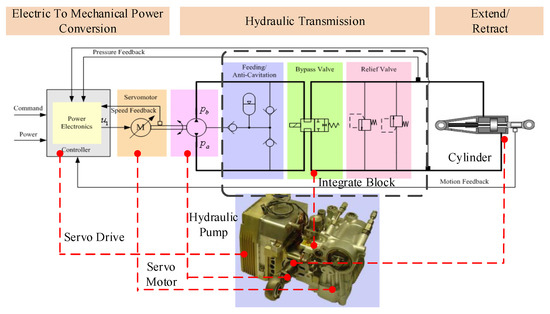
Figure 1.
Schematic diagram of an electro-hydrostatic actuator (EHA).
In the early phases of an EHA design project, only a few design parameters are available, but a lot design parameters have to be decided and several properties should be considered simultaneously. It is well-known that early verification and virtual validation of the system design in the preliminary design phase, based on advanced simulations and computational tools, can significantly reduce the cost and enhance the quality of the design process. Some researchers have studied simulation-based preliminary design methods for aircraft actuator design, sizing, analysis, and optimization in recent years. A simulation-based preliminary design and optimization method of an electro-mechanical and hydraulic actuation system for an aircraft flight control surface was proposed by Fraj et al. [8], where the weight was the optimized objective and the weight estimation models of major components of actuator were presented. An improved integrated methodology for the preliminary design of electromechanical actuators in a redundant electro-mechanical nose-gear steering system was published by Liscouët et al. [9]. In order to obtain the properties of an electro-mechanical actuator (EMA) for multi-objective optimization in preliminary design, the estimation models for power size, thermal balance, dynamics, and reliability were studied by Budinger et al. [10]. After that, Budinger et al. [11] presented a methodology for the optimal preliminary design of EMAs. A MATLAB/Simulink-based methodology for the sizing, simulation, analysis, and optimization of both EHAs and EMAs, for the primary and secondary control surfaces of a more-electric aircraft (MEA), was proposed by Chakraborty et al. [12]. After that, in Chakraborty et al. [13], an electric control surface actuator design optimization and allocation for MEA was studied. Recently, a multi-level virtual prototyping of EMAs, using bond-graph modeling method, was proposed by Fu et al. [14], FU et al. [15]. However, most of these studies did not take advantage of intelligent optimization methods to find optimal design parameters; therefore, they cannot provide strong support for designers.
The most important properties of EHA includes light-weight, less energy consumption, quick response, and high stiffness to disturbance. These objectives usually conflict with each other and are hard to balance. Therefore, using a multi-objective optimization (MOO) method to design an EHA leads to more preferable solutions. MOO methods usually obtain a set of Pareto-optimal solutions, instead of a single optimal solution Marler and Arora [16]. The Pareto front is able to indicate the relations between the design parameters and the desired performance, which is very useful for the engineer to achieve an optimal design. In order to offer support for preliminary design of MEA, Wu et al. [17] proposed estimation models for the weight and efficiency of EHA, and a multi-objective optimization algorithm to get the Pareto front of considered performances. In the following work by Yu et al. [18], an estimation model of stiffness was considered and a synthesis decision-making method, based on an analytic hierarchy process (AHP), was used to choose the best solution in the Pareto front. This method can offer significant support to engineers in system design. However, it didn’t integrate with a simulation tool and, thus, could not evaluate the dynamic performance.
The present work aims to offer an efficient and powerful simulation-based multi-objective optimization design method for fast and easy preliminary design of EHA. This methodology can search the design parameters automatically, which will make the EHA have Pareto-front performances. This study considered the four important indexes of weight, energy consumption, dynamic response, and stiffness. The weight of the actuator is predicted, based on a scale law according to the design parameters. The performances of energy consumption, dynamic response, and stiffness are obtained by dynamic simulation with AMESim. The intelligent optimization program sent the parameters to the AMESim model, and then ran the simulation and analyzed the dynamic performances (according to the simulation results) automatically. The MOO method of the program in present study is the multi-objective particle swarm optimization (MOPSO) method. The results present the mapping between parameters to the performance and the relations between these objectives. It also illustrated that the proposed method has the significant benefits in the design of EHA and other similar systems.
2. MOO Design Method of EHA
For the design of systems with high integration and complex structure, such as EHA actuation systems, choosing the design parameters to get a satisfactory performances is a difficult task, as there ae typically many objectives to be considered, such as light weight, high energy efficiency, good dynamic performance, and stiffness. Furthermore, these objectives usually conflict with each other. This is a MOO problem which usually needs a method to find the Pareto front of all the objectives intelligently.
Modeling and simulation are important tools in modern design, which can obtain the performances quickly by using a computer. There are some powerful modeling and simulation tools for electrical and hydraulic system design, such as AMESim. In AMESim, an EHA system can be modeled and simulated, with high precision and without too much effort. However, setting and optimizing the parameters is a daunting task, since there are a number of parameters which should be decided and the engineer has to go through a lot of simulation curves to judge the performances, which usually needs expert experience and takes a lot of labor time. If the model calculation does not obtain an ideal control state, the designer needs to find the improper parameters and simulate again and again, until the results are satisfactory. However, a “satisfying” result is usually not the optimal solution, since the designer can not continue to optimize the parameters for a long time. In summary, the manual simulation-based design methods rely on the experience of the designer and increases the time cost of system development. Obviously, the traditional approach to designing EHA is outdated, in the current era of “automation and intelligence”. Therefore, improving design efficiency is a problem for these highly complex system design methods.
2.1. Description of the Proposed Method
Fortunately, the interface of python is provided by AMESim. Python is a powerful, well-scalable program language in artificial intelligence. It has a lot of libraries for scientific analysis and optimization, which are easy to use. Therefore, a model-based intelligent optimization method with python is proposed in the present study. The model of an EHA driving a flight control surface is carried out by AMESim. The developed python script can generate design parameters by using an intelligent search method, and transfers them to the AMESim model. Then, the python script can run a simulation of the AMESim model with a pre-defined motion and load scenario of the control surface. The python script also can get the results when the simulation is finished, which can be used to evaluate the performance as the objective of optimization. Therefore, using the proposed intelligent design method cannot only greatly save labor costs, but also shorten the system development time.
The flow chart of the developed intelligent optimization method is shown in Figure 2. The intelligence MOO method will update the parameters, based on the search algorithm, to get the optimal solutions by iteration until the Pareto front of the design is obtained. The entire intelligent MOO design process can be described as:
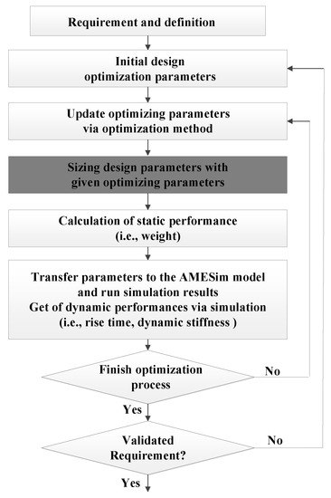
Figure 2.
Flowchart of the intelligent optimization design process, based on python.
- Build the AMESim model of EHA and initialize the model parameters randomly in the defined range.
- Simulate and analyze the static and dynamic performances of the EHA.
- Determine whether the design requirements are met. If not, the multi-objective optimization (MOO) algorithm will search the design parameters by the intelligent search algorithm.
- The MOO method generates the design parameters, based on the search algorithm, and sends these parameters to the AMESim model of EHA.
- Jump to the step 3 and return the performance metrics to the MOO algorithm for comparison.
- Cycle through steps 3 to 6, until the Pareto front of the designs is obtained.
- Validate whether the design requirements are all satisfied; if not, jump to step 2 to re-define the optimization parameters range and conditions.
2.2. Modeling the EHA System with AMESim
A diagram of the location of an EHA in the aircraft wing profile is shown in Figure 3, and the AMESim model of a flight control surface actuation system by EHA is shown in Figure 4. It consists of an EHA, a flight control surface, and a controller. The model in the red-dashed box is the EHA, which contains all the major parts of an EHA (motor, pump, anti-cavitation device, safety valves, and selector valve). The model in the green-line box is the controller. Only a simple three-loop (displacement, velocity, and current) controller is used in the present work, since the controller is not the purpose. The controller generates the command (as voltage) to drive a direct current motor, where the shaft of the motor is connected to a hydraulic fixed-displacement pump. The pump drives the actuator through a hydraulic circuit, which consists of re-feeding valves with a compensating hydraulic accumulator for anti-cavitation, a mode selector valve to select the mode (damping or active), and two pressure relieve valves for safety. The piston of the actuator moves the flight control surface of the aircraft, and the control surface is modeled with a planar mechanical 2D library, which can simulate the external load more realistically. This model has all the major parameters of the EHA system in the application scenario and the performance under different parameters can be obtained and evaluated.
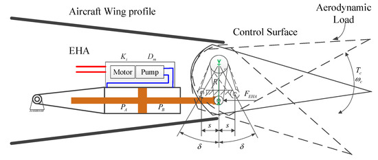
Figure 3.
Diagram of the location of the EHA in the aircraft wing profile.
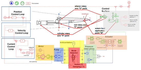
Figure 4.
Model of an EHA actuation system in AMESim.
In order to evaluate the performances of the EHA system, a typical angle command and load scenario of flight control surface is constructed, which is shown in Figure 5. The aerodynamic load include two parts; elastic load (proportional to the angle) and disturbance load. The angle and load commands include different conditions to evaluate different control performances, which are:

Figure 5.
Dynamic response of a defined angle command and load scenario.
- A low-frequency sinusoid angle command is set in the first 5 s to evaluate control precision;
- a step angle change is set from 5–11 s to obtain the rise time, in order to evaluate the dynamic performance;
- a wind gust is simulated during 11–15 s, while the control surface is held at a constant-angle position, to evaluate the dynamic stiffness; and
- some higher frequency sinusoid angle commands are also included, and the total input energy of electrical motor during the 20 s is used to evaluate the energy consumption performance.
2.3. Sizing Design Parameters
The fourth step of the flow chart in Figure 2 is sizing the design parameters with given optimization parameters. This is an important process, and its diagram is illustrated in Figure 6. The inputs of the sizing process are the requirements of a control surface, which includes maximum hinge moment (), maximum rotation velocity (), and deflection angle (). For a flight control application, the EHA drives the control surface deflection by a level. Therefore, the level length (R) is a key parameter that affects the parameters of the EHA actuation system significantly. The maximum force (F), maximum speed (v), and linear stroke (s) can be calculated by (R) and (), (), and (). When the working pressure () of the EHA system is determined, the relevant parameters of the hydraulic cylinder can also be determined, such as the piston area () and the flow rate. The second key parameter that needs to be determined is the displacement of the hydraulic pump (). As shown in Wu et al. [17], the maximum speed of the pump () is limited by the displacement of the hydraulic pump. The torque of the motor () can be obtained by the product . Usually, the maximum current is limited by the servo motor driver, and then the torque constant of the motor () is known. The weight of the EHA can be estimated, based on the scaling law in Wu et al. [17] with the sizing parameters. The parameters also will be transferred to the AMESim model and the dynamic performances can be obtained after running a simulation. In summary, the selected optimization design variables in this paper are (R) and (), and the optimization targets are weight, energy consumption, rise time, and dynamic stiffness.
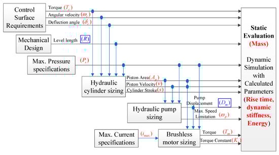
Figure 6.
Diagram of the design process in the EHA parameter optimization.
3. Multi-Objective Optimization of EHA
In the present study, four objectives are considered for optimization. Therefore, the evaluation model of these four objectives should be integrated into the optimization program. These four objectives include both static and dynamic performances, requiring different evaluation methods which will discussed in the present section.
3.1. Weight Prediction Model of EHA
Weight is an important property which should be minimized for aerospace applications. As shown in Figure 1, a EHA mainly has five basic parts: Pump, motor, cylinder, manifold, and power electronics. The total weight of the EHA can be defined as the sum of the gross weights of the five parts. In order to evaluate the weight of the EHA with the major design parameters in the preliminary design phase, two weight estimate methods are employed in the present study. The weight prediction, with the design parameters, usually uses the scaling law. It has the advantage of requiring only one reference component for a complete estimation of a product range [8,10]. More details of mass prediction of other components can be found in [8,17].
3.2. Energy Consumption Index of EHA
Energy efficiency is another key characteristic for EHA. Some previous works used the design parameters to calculate the efficiency of EHA, but could not evaluate energy consumption well since it is related to the working condition. In the present study, the energy consumption is indexed by the total energy input of EHA to finish the pre-defined representative simulation task. The integration of input power of the electrical motor is the energy consumption of the EHA, which can be expressed as:
where and are the input voltage and current of the motor, which can be obtained from the dynamic simulation results; and T is the simulation time of the typical scenario.
3.3. Dynamic Response Performance Index of EHA
The dynamic performance is very important for EHA and it usually can be evaluated by rise time (). The smaller , the faster the system responds. The rise time is evaluated by the dynamic simulation. The reference angle has a step variation, and the EHA need to control the control surface to follow the reference signal. The time between to of step usually defined as the rise time. As can be seen from the Figure 5, the can be expressed as:
where and are the time corresponding to the response curve being and of the steady state value, respectively.
3.4. Dynamic Stiffness of EHA
Dynamic stiffness is also an important indicator for evaluating the dynamic performance of EHA. Low dynamic stiffness can severely degrade the control accuracy of the system. Hydraulic spring effects are a major part of the EHA stiffness. Therefore, the stiffness of the hydraulic spring is considered as an objective in this study. The dynamic stiffness is evaluated by the root-mean square (RMS) of the angle of control surface offset from the given value, during 12–15 s in the simulation. When the EHA holds the control surface stalled at a constant position under wind gust disturbance, more stiffness will result in a smaller RMS value.
4. Multi-Objective Optimization Method Description
The design parameters are searched by the MOO method, instead of manually adjusting, to improve design efficiency. Various objectives usually conflict with each other, which means improving one objective usually comes at the expense of reducing the character of another. The MOO method can search for the solution set that can not improve any one objectives without reducing other objectives, which usually is called the Pareto front.
Various MOO methods have been proposed, including the multi-objective particle swarm optimization (MOPSO) algorithm Coello et al. [19], the fast non-dominated sorting genetic algorithm (NSGA-2) method Deb et al. [20], DEB [21], andthe Pareto-frontier differential evolution (PDE) approach Abbass et al. [22], among others. In the present study, the (MOPSO) method is employed as it has the advantage of very good global searching capability.
The pseudo-code of the MOPSO method in the present study can be described as:
- Initialize each particle of the population.
- Update (initialize in the first loop) the position of each particle with parameter values of (, ), according to the multi-objective particle swarm optimization algorithm.
- Evaluate each of the particles and get the weight and according dynamic parameters by parameters. Send the dynamic parameters to the simulation model and run a simulation with the updated parameters. Calculate the dynamic objectives and assign the fitness value to the particle.
- Store the positions (parameters) of the particles that represent non-dominant vectors in the repository.
- Select the non-dominated particles (according to the Pareto dominance relation) and put them into the non-dominated set.
- Compute the speed of each particle using Equation (3) and compute the new position of the particles adding current parameter with the speed.where is the best position in the whole search history; is the selected leader from the repository; w represent the inertia coefficient of velocity; and are local and social coefficients, respectively; and and are two random values in the range . Then, the position is updated at each iteration based on the velocity.
- Determine whether the maximum count of iterations has been reached or not. If the maximum number of iterations has not been reached, go back to the step 2. Otherwise, stop the optimization process and return the Pareto front stored in the repository.
5. Optimization Results and Discussion
A case of EHA system optimization is presented, in order to validate the feasibility of the proposed method. The design requirements of a typical control surface are listed in the Table 1. The maximum voltage is and maximum current is set to . The maximum pressure of EHA is set to . In the optimization process, the optimization method generates the radius of the lever and the displacement of the pump . Then the parameters of the EHA (i.e., the area of the piston, the stroke of the cylinder, the rotational inertia of the motor and pump, and the torque constant of the motor) can be calculated. These parameters are transferred to the AMESim model and the simulation is run. Then, the simulation results are obtained and the dynamic objectives can be analyzed automatically by the program.

Table 1.
Control surface requirements.
Consider the application condition, where the range of the two optimization parameters are set as shown in Table 2. These two parameters decide the major characteristics of the EHA. A longer lever means the force requirement of the EHA is small but the stroke should be longer, in a slender form. On the contrary, a shorter lever means a large force requirement and short stroke. A larger displacement of the pump requires low rotary speeds for a desired flow rate, which will make the motor and pump more heavy, but can improve the efficiency and may make the EHA response quicker. These conflicting objectives make it hard to find a solution to trade off all performances. It usually required of MOO design methods to find the Pareto Front to help the engineer in the design process.
Table 2.
Range of optimization parameters.
The parameters of MOPSO, in the present study, include the number of particle population , maximum repository capacity of the Pareto front is 100, , , and the maximum iteration count is 10. The Pareto fronts of each of the two objectives are shown in Figure 7. These figures show that the weight and energy consumption trade off against each other. The results also indicate that the rise time and weight also trade off against each other. The rise time and energy consumption are positively correlated. The relationships between dynamic stiffness and the other performances are more complicated, as they are not monotonous functions. These relationships between objectives are useful for designers to balance different performances. The results also indicate that the proposed method can search the Pareto front solutions intelligently, which can save huge effort in adjustment by the engineer.
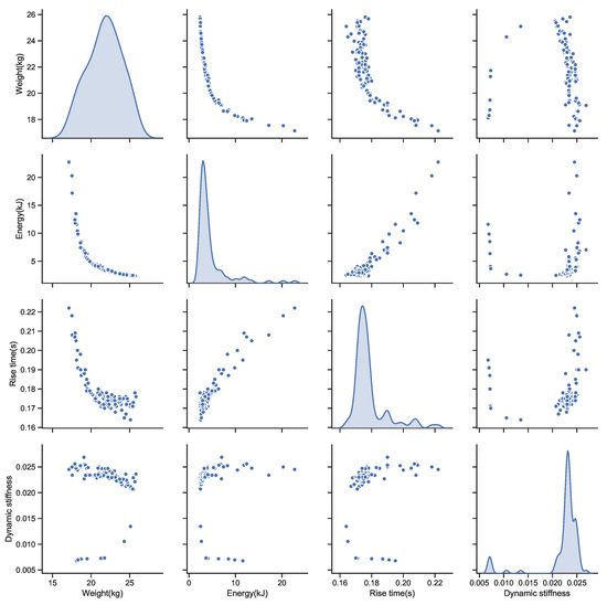
Figure 7.
Scatter graph of the optimization results, including the Pareto front of each two objectives and the distribution of the each objective.
The relationships between the parameters and the objectives are shown in Figure 8. The weights of the solutions in the Pareto front, with design parameters, are shown in the upper right of Figure 8. The lightest solution is with the lever length about 125 mm, and a displacement of about mL/rev. Compared to the energy consumption and rise time, the lightest solution had the biggest energy consumption and slowest response. The most efficient solution is locating at mL/rev and lever length of 103 mm. However, this solution also had a high weight and low dynamic stiffness. The optimization results indicate that using a smaller displacement pump is beneficial for reducing weight and increasing dynamic stiffness. Using a bigger displacement pump will improve the efficiency and make the EHA response quicker, but will make the EHA more heavy. The designer can get all design parameters and performance indices, as in Figure 8, of the solutions in the Pareto front, then they can choose one solution which is most satisfactory for the application. Thus, the proposed method can offer significant support for the engineer.
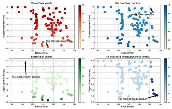
Figure 8.
Objective locations in the design space of the Pareto front.
The time domain performances of four typical solutions in the Pareto front (the lightest solution, the quickest solution, the most efficient solution, and the best stiffness solution) are simulated. The simulation results are illustrated in the Figure 9. All of these four solutions obtain an acceptable control performance, only having a little difference in dynamic response; but the weight and energy consumption had a large disparity. This means the weight and energy consumption can be reduced, if appropriate parameters are given. The Pareto front obtained by the proposed method is very helpful for the engineer to determine the design parameters.
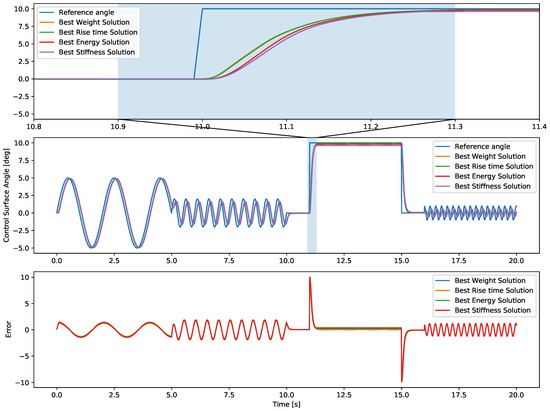
Figure 9.
Dynamic simulation results of four types of typical design parameters.
6. Conclusions
This paper presents a simulation-based intelligent multi-objective optimization method of a pump-driven electro-hydrostatic actuator with AMESim and a python script. The model of an EHA driving a flight control surface is carried out by AMESim. The python script generates design parameters by using an intelligent search method and transfers them to the AMESim model. Then, the script can run a simulation of the AMESim model with a pre-defined motion and load scenario of a control surface. The python script also can obtain the results when the simulation is finished, which can then be used to evaluate the performance as the objective of optimization. The multi-objective particle swarm optimization (MOPSO) method is applied to obtain the Pareto front of solutions. In the present study, the design parameters of level length and pump displacement of the pump are optimized. An application case of optimizing an EHA driving a flight control surface is studied to validate the proposed method. Both the static objectives of weight and dynamic performances of energy consumption, rise time, and dynamic stiffness are considered. These four performances are very important for an EHA and should be optimized simultaneously. The Pareto front of these four objectives is obtained with the relevant design parameters. The results present the mapping between the design parameters to the performance and the relations between these objectives. This work indicated the proposed MOO method and this platform can be used in the design phase to help engineers to determine the design parameters according to the required performance. It is also envisaged that the proposed method can be used in similar design problems.
Author Contributions
Investigation, L.X.; Simulation and Analysis, L.X. and S.W.; Methodology, S.W.; Software, S.W.; Writing and Editing, L.X.; Validation, Y.X.; Project Administration D.M.
Funding
This research was funded by National Aviation Science Foundation (Grant No. 20160751003) and National Science Fundation of China (Grant No. 51890885, 51775014).
Conflicts of Interest
The authors declare that there is no conflict of interest regarding the publication of this paper.
Abbreviations
The following abbreviations are used in this manuscript:
| EHA | Electro-hydrostatic Actuator |
| MEA | More Electric Aircraft |
| MOO | Multi-Objectives Optimization |
| MOPSO | Multi-Objectives Particle Swarm Optimization |
References
- Rosero, J.; Ortega, J.; Aldabas, E.; Romeral, L. Moving towards a more electric aircraft. IEEE Aerosp. Electron. Syst. Mag. 2007, 22, 3–9. [Google Scholar] [CrossRef]
- Rongjie, K.; Zongxia, J.; Shaoping, W.; Lisha, C. Design and simulation of electro-hydrostatic actuator with a built-in power regulator. Chin. J. Aeronaut. 2009, 22, 700–706. [Google Scholar] [CrossRef]
- Van Den Bossche, D. The A380 flight control electrohydrostatic actuators, achievements and lessons learnt. In Proceedings of the 25th Congress of the International Council of the Aeronautical Sciences, Hamburg, Germany, 3–8 September 2006. [Google Scholar]
- Charrier, J.; Kulshreshtha, A. Electric actuation for flight and engine control; evolution and current trend & Future Challenges. In Proceedings of the 45th AIAA Aerospace Sciences Meeting and Exhibit, Reno, Nevada, 8–11 January 2007; Volume 1391. [Google Scholar]
- Chao, Q.; Zhang, J.; Xu, B.; Huang, H.; Pan, M. A Review of High-Speed Electro-Hydrostatic Actuator Pumps in Aerospace Applications: Challenges and Solutions. J. Mech. Des. 2018, 141, 050801. [Google Scholar] [CrossRef]
- Chao, Q.; Zhang, J.; Xu, B.; Shang, Y.; Jiao, Z.; Li, Z. Load-Sensing Pump Design to Reduce Heat Generation of Electro-Hydrostatic Actuator Systems. Energies 2018, 11, 2266. [Google Scholar] [CrossRef]
- Shang, Y.; Li, X.; Wu, S.; Pan, Q. A Novel Electro Hydrostatic Actuator System with Energy Recovery Module for More Electric Aircraft. IEEE Trans. Ind. Electron. 2019. [Google Scholar] [CrossRef]
- Fraj, A.; Budinger, M.; El Halabi, T.; Maré, J.C.; Negoita, G.C. Modelling approachs for the simulation-based preliminary design and optimization of electromechanical and hydraulic actuation systems. In Proceedings of the 53rd AIAA/ASME/ASCE/AHS/ASC Structures, Structural Dynamics and Materials Conference, Orlando, FL, USA, 12–15 April 2012; In Proceedings of the 20th AIAA/ASME/AHS Adaptive Structures Conference, Orlando, FL, USA, 12–15 April 2012; In Proceedings of the 14th AIAA, Orlando, FL, USA, 12–15 April 2012. p. 1523. [Google Scholar]
- Liscouët, J.; Maré, J.C.; Budinger, M. An integrated methodology for the preliminary design of highly reliable electromechanical actuators: Search for architecture solutions. Aerosp. Sci. Technol. 2012, 22, 9–18. [Google Scholar] [CrossRef]
- Budinger, M.; Liscouet, J.; Hospital, F.; Mar, J.C. Estimation models for the preliminary design of electromechanical actuators. Proc. Inst. Mech. Eng. Part G J. Aerosp. Eng. 2012, 226, 243–259. [Google Scholar] [CrossRef]
- Budinger, M.; Reysset, A.; El Halabi, T.; Vasiliu, C.; Maré, J.C. Optimal preliminary design of electromechanical actuators. Proc. Inst. Mech. Eng. Part G J. Aerosp. Eng. 2014, 228, 1598–1616. [Google Scholar] [CrossRef]
- Chakraborty, I.; Jackson, D.; Trawick, D.R.; Mavris, D. Development of a Sizing and Analysis Tool for Electrohydrostatic and Electromechanical Actuators for the More Electric Aircraft. In Proceedings of the 2013 Aviation Technology, Integration, and Operations Conference, Los Angeles, CA, USA, 12–14 August 2013; pp. 1–17. [Google Scholar] [CrossRef]
- Chakraborty, I.; Trawick, D.; Jackson, D.; Mavris, D. Electric Control Surface Actuator Design Optimization and Allocation for the More Electric Aircraft. In Proceedings of the 2013 Aviation Technology, Integration, and Operations Conference (AIAA Aciation), Los Angeles, CA, USA, 12–14 August 2013; p. 4283. [Google Scholar]
- Fu, J.; Maré, J.C.; Fu, Y. Modelling and simulation of flight control electromechanical actuators with special focus on model architecting, multidisciplinary effects and power flows. Chin. J. Aeronaut. 2017, 30, 47–65. [Google Scholar] [CrossRef]
- Fu, J.; Mare, J.C.; Yu, L.; Fu, Y. Multi-level virtual prototyping of electromechanical actuation system for more electric aircraft. Chin. J. Aeronaut. 2018, 31, 892–913. [Google Scholar] [CrossRef]
- Marler, R.T.; Arora, J.S. Survey of multi-objective optimization methods for engineering. Struct. Multidiscip. Optim. 2004, 26, 369–395. [Google Scholar] [CrossRef]
- Wu, S.; Yu, B.; Jiao, Z.; Shang, Y.; Luk, P.C.K. Preliminary design and multi-objective optimization of electro-hydrostatic actuator. Proc. Inst. Mech. Eng. Part G J. Aerosp. Eng. 2017, 231, 1258–1268. [Google Scholar] [CrossRef]
- Yu, B.; Wu, S.; Jiao, Z.; Shang, Y. Multi-Objective Optimization Design of an Electrohydrostatic Actuator Based on a Particle Swarm Optimization Algorithm and an Analytic Hierarchy Process. Energies 2018, 11, 2426. [Google Scholar] [CrossRef]
- Coello, C.; Pulido, G.; Lechuga, M. Handling multiple objectives with particle swarm optimization. IEEE Trans. Evol. Comput. 2004, 8, 256–279. [Google Scholar] [CrossRef]
- Deb, K.; Agrawal, S.; Pratap, A.; Meyarivan, T. A Fast Elitist Non-dominated Sorting Genetic Algorithm for Multi-objective Optimization: NSGA-II. Lect. Notes Comput. Sci. 2000, 1917, 849–858. [Google Scholar]
- Deb, K. A fast elitist non-dominated sorting genetic algorithm for multi-objective optimization: NSGA-2. IEEE Trans. Evol. Comput. 2002, 6, 182–197. [Google Scholar] [CrossRef]
- Abbass, H.; Sarker, R.; Newton, C. PDE: A Pareto-frontier differential evolution approach for multi-objective optimization problems. In Proceedings of the 2001 Congress on Evolutionary Computation, Seoul, Korea, 27–30 May 2001; Volume 2, pp. 971–978. [Google Scholar] [CrossRef]
© 2019 by the authors. Licensee MDPI, Basel, Switzerland. This article is an open access article distributed under the terms and conditions of the Creative Commons Attribution (CC BY) license (http://creativecommons.org/licenses/by/4.0/).