Article

Numerical Study of Pressure Fluctuation and Unsteady Flow in a Centrifugal Pump

1
National Research Center of Pumps, Jiangsu University, Zhenjiang 212013, China
2
School of Mechanical Engineering, Nantong University, Nantong 226019, China
*
Authors to whom correspondence should be addressed.
Processes 2019, 7(6), 354; https://doi.org/10.3390/pr7060354
Submission received: 9 May 2019 / Revised: 30 May 2019 / Accepted: 4 June 2019 / Published: 9 June 2019
(This article belongs to the Special Issue Smart Flow Control Processes in Micro Scale)

Abstract

:
A pump is one of the most important machines in the processes and flow systems. The operation of multistage centrifugal pumps could generate pressure fluctuations and instabilities that may be detrimental to the performance and integrity of the pump. In this paper, a numerical study of the influence of pressure fluctuations and unsteady flow patterns was undertaken in the pump flow channel of three configurations with different diffuser vane numbers. It was found that the amplitude of pressure fluctuation in the diffuser was increased gradually with the increase in number of diffuser vanes. The lower number of diffuser vanes was beneficial to obtain a weaker pressure fluctuation intensity. With the static pressure gradually increasing, the effects of impeller blade passing frequency attenuated gradually, and the effect of diffuser vanes was increased gradually.

1. Introduction

Centrifugal pumps are of vital importance for a variety of commercial and industrial applications [1], which could handle a great quantity of liquids at relatively high pressures [2]. For those applications that require extremely high pressures, multistage centrifugal pumps, which usually have more than two or even up to dozens of stages, are used. Owing to the high reliability requirements for a long shaft, the hydraulic design of the multistage centrifugal pumps is more complex than that of the single-stage pumps [3]. Recently, many researchers have conducted both numerical simulations and experiments on the efficiency of multistage centrifugal pumps to enhance their hydraulic design [4,5,6].
The operation process of multi-stage centrifugal pumps is often accompanied by vibration and noise. When the pump produces static pressure, it also produces dynamic pressure, which is also named as pressure fluctuation along with the periodic changing features like AC signal. Pressure fluctuations are inevitable during the operation of a pump, having strong unsteady characteristics that may lead to strong vibration and noise under some special working conditions [7].
In previous studies, a series of numerical investigations of pressure fluctuations within a complete single-stage centrifugal pump were undertaken. Khalifa et al. [8] investigated the pressure fluctuations and vibration in a single-stage centrifugal pump experimentally under different flow conditions. They found that under different flow rates, the vibrations have a close relationship with the pressure fluctuations, and the vibration could be controlled by optimizing the gap between the volute tongues and the impeller. Guelich et al. [9] studied the physical mechanisms behind the pressure fluctuations under the design flow conditions. They found that the pressure fluctuations mainly depend on the geometry of the diffuser and the impeller by performing 36 tests with different pump designs. Spence et al. [10] used the multi-block, structured mesh CFD (Computational Fluid Dynamics) code TASC flow to study the pressure fluctuations in a centrifugal pump for three different flow rates. They found that the volute gap and the arrangement of vanes have the greatest effect on the different monitored positions. In a previous work of ours [11], we simulated the transient flow field of a centrifugal pump by employing ANSYS-CFX software based on the frozen rotor technique and utilizing the Shear Stress Transport (SST) k-ω turbulence model. The results shown that the pressure fluctuation is mainly affected by the number of impeller blades, but the influence decreased gradually when the water flowed into the diffuser. Pei et al. [12] focused on the numerical simulation of unsteady flow under part-load conditions, the results shown that the intensity of pressure fluctuation is larger than that of design flow condition because of leakage flow. Jiang et al. [13] studied the clocking effect and unsteady radial force in a centrifugal pump by numerical and experimental methods, they found that the unsteady flow and pump performance mainly effected by the relative position between the diffuser the volute. Wang et al. [14] carried out an experimental measurement to study the influence of rotating speed and flow rate on the pressure fluctuation in a double-suction centrifugal pump. They found that the pressure fluctuation under zero flow rate is two times that of the pressure fluctuation under the design flow rate. Posa and Lippolis [15] used Large Eddy Simulations (LES) to investigate the influence of diffuser setting angle and operating conditions on the pressure fluctuation and unsteady flow in a centrifugal pump. They found that the larger radial gaps between diffuser and impeller could lead to lower pressure fluctuations, but the lower flow rate could lead to higher pressure fluctuations.
While numerous studies have investigated the pressure fluctuation and unsteady characteristics in different kinds of pumps, which includes the effects of working conditions [14,16], inlet guide vanes [17], tip clearance [18], and volute curvature [19,20,21], but the influence of the number of diffuser vanes on the pressure fluctuation in the centrifugal pump is unclear and further investigation is needed. So, in this paper a numerical approach was adopted in a centrifugal pump with a different number of diffuser vanes, and the pressure fluctuations are analyzed and compared in detail. The results could supply a basis for further design improvement of the pump body structure and working reliability.

2. Pump Geometry

In this study, we have chosen a standard Electrical Submersible Pump (ESP) as the research objective. The main design parameters of this ESP are as follows: design flow rate Qdes = 36 m3/h; rotating speed n = 2850 r/min; total head H = 75 m; number of stages N = 7; specific speed ns = 175.8; design efficiency η = 72%; and maximum power P = 11 kW. More details about the parameters of pump geometry could be found in one of our previous paper [22].
This kind of ESP is usually manufactured with plastic materials, in order to ensure there is enough space for the unloading of casting, so the impeller was designed with five blades. In most cases, the number of diffuser vanes is selected to be relative prime number with the number impeller blades. In order to study the effects of the diffuser vanes number on the unsteady flow and pressure fluctuation, the same profile was used for the diffuser vanes and their number was adjusted to 6, 7, and 8 for three different configurations. The solid model of the impeller is shown in Figure 1, and the three configurations with different diffuser vanes number are shown in Figure 2.

3. Mathematical Model

The Navier–Stokes equation (N–S) and continuity equation of an incompressible fluid are [23]:
u i t + u j u i x j + 1 ρ p x ν 2 u i = 0 ,
u i x i = 0 .
where 2 is Laplace operator, ui is the flow velocity component in i direction, i = 1, 2, 3 respectively represent the flow velocity component in the three directions of x, y, z.
Carrying out partial derivative operations on the Equation (1) we get:
2 u i t x i + u j x i u i x j + u j 2 u i x i x j + 1 ρ 2 p x i 2 ν 2 u j x i = 0 .
Using formula (2) into Equation (3) we get:
2 p x i 2 = 2 p = ρ ( u i x j u j x i ) .
If u i = u i + u i , u j = u j + u j ,   p = p + p , put them into Equation (4) and Equation (2) to get:
2 p ¯ + 2 p = ρ 2 x i x j ( u i u j ¯ + u i ¯ u j + u i u j ¯ + u i u j ) ,
u i ¯ x i + u i x i = 0 ,
where u i ¯ , u j ¯ , p ¯ represent time-averaged value, u i , u j , p represent fluctuating value, u i = u i ¯ , u j = u j ¯ ,   p = p ¯ , u i ¯ = 0 , u j ¯ = 0 , p ¯ = 0 .
Taking the average of Equations (5) and (6) separately we get:
2 p ¯ = ρ 2 x i x j ( u i u j ¯ + u i u j ¯ ) ,
u i ¯ x i = 0 .
Substituting Equation (7) from Equation (5) to obtain the expression of pressure fluctuation equation:
2 p = ρ [ 2 ( u i ¯ u j + u i u j ¯ ) x i x j + 2 x i x j ( u i u j u i u j ¯ ) ] .
Equation (6) minus Equation (8) we obtain the expression of pressure fluctuation continuous equation:
u i x i = 0 .
Using Equation (10) into Equation (9) we finally get:
2 p = ρ [ 2 u i ¯ x j u j x i + 2 x i x j ( u i u j u i u j ¯ ) ] ,
where ρ is the density of water, p is pressure fluctuation, u i is fluctuating velocity, u i ¯ is time-averaged velocity.
Equation (11) indicates that the pressure fluctuation is mainly caused by the fluctuation of velocity, the first term on the right-hand side of the equation represents the interaction between mean velocity and fluctuating velocity, which is the mean velocity field distortion and generally called a “quick response term” [24,25]. The time-averaged velocity gradient expresses mean shear stress term, therefore, it is also known as the “turbulence-shear”. The second term on the right side of the equation is the change of pressure fluctuation caused by the nonlinear effect in the fluctuating velocity field, commonly known as “turbulence-turbulence”. Equation (11) can be understood as the basic equation of pressure fluctuation, in which we can see that pressure fluctuation is equal to the comprehensive effects of the two categories of the effects in brackets of the right side: the first category is the interaction of “shear-turbulence”, and the second category is the interaction of “turbulence-turbulence”. At the same time, it can be seen from the Equation (11) that there is no direct relation between the viscosity of the fluid and the pressure fluctuation. The viscosity of the fluid only plays an indirect role in pressure fluctuation [25].

4. Numerical Setup

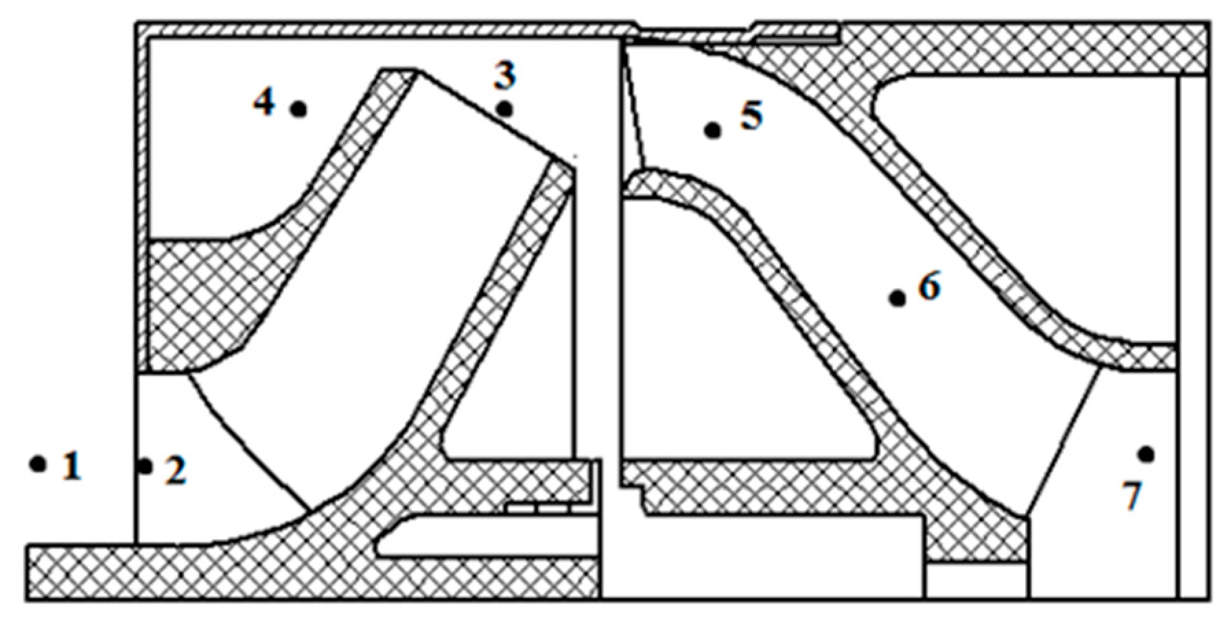
4.1. Computational Domain

The solid models were created and assembled to form the computational domain in Pro/E Wildfire 5.0 software, which include the inlet section, impeller, diffuser, lateral cavity, and outlet section [26]. In order to balance the total grid number of points, calculation time, and the computer capability [27], only one stage model was chosen in this study, as shown in Figure 3.

4.2. Meshes

ANSYS-ICEM-CFD 14.5 software [28] was used to build the structured meshes associated with the block topology of Y-type and O-type. The mesh growth rate of boundary layer were considered to ensure the overall mesh thickness and density. The appropriate mesh density was decided according to the gird independence test [29,30]. Table 1 summarizes five schemes of different mesh numbers. By comparing the pump performance predicted by the same numerical methods we found that with the increase of mesh number, the numerical value of single-stage head, single-stage power, and efficiency show a stable trend. Between the schemes No. 4 and No. 5, increasing mesh has no influence on the simulation results, which means that the scheme No. 4 has enough accuracy with enough mesh density. Therefore, by considering the grid independence test and the computer capability, scheme No. 4 was selected as the optimal scheme of mesh for the numerical investigation. For the whole single-stage computational domain, the total of mesh elements is almost 4.9 million. Meanwhile, it was ensured that the entire computational domain 30 < y+ < 60, which indicates that the near-wall mesh nodes are in a log-law layer. Figure 4 is the final mesh used for the impeller and the diffuser.

4.3. Numerical Settings

ANSYS-Fluent 14.5 software [31] was used to run the numerical simulation for this study, in which the SST k-ω turbulence model, and the SIMPLEC algorithm was used to solve the discrete difference equations of the second-order upwind scheme. As shown in Figure 5, no-slip boundary conditions were used on the wall surface, inlet boundary conditions of mass flow were used on the pump inlet, and outlet boundary conditions of pressure were used on the outlet of the pump. For instance, the mass flow rate for inlet was set as 10 kg/s at the design flow rate, and the total pressure for the outlet was set as 10,135 Pa. Using sliding grid technology, the impeller region in the flow channel was set to be a rotating grid coordinate system provided by ANSYS-Fluent, while the diffuser and other hydraulic components were set to be a stationary coordinate system. After reaching convergence of steady calculation based on the fixed rotor coordinate system (Frozen Rotor), the flowfield was used as the initial value to start the unsteady calculation. The Principle of a Frozen Rotor is to set the impeller part to be a rotating reference coordinate system, and the static and dynamic interface is coupled by combing with sliding mesh technology [32,33].

4.4. Time Step

In general, in the periodic numerical simulation, the time step needs to satisfy the Courant number criterion [34], which is expressed as:
C o = | v ¯ | Δ t l 100 .
In the above formula, | v ¯ | is the absolute value of the estimated mean velocity, l is the smallest size of the grid, and Co is required to be no more than 100. When the numerical convergence is not good, it is appropriate to take smaller values.
According to the requirement of sampling theorem, 2.56–4 times of the signal maximum frequency is selected generally for the time step. In this study, the impeller has five blades, the rotational speed is 2850 r/min, so the blade passing frequency (BPF) is 332.5 Hz. If there are at least seven points in a BPF cycle, and the desirable maximum value of the time step is 4.2966 × 10⁻⁴ s accordingly.
If the time step size is too large, some minor changes of the pressure will not be captured, but time steps that are too small will also lead to a significant increase in computing time [35,36]. Therefore, considering the computer configuration, the time step △t was chosen as 5.8478 × 10⁻⁵ s, the impeller rotated one degree for one time step, 360 time steps were required for each rotation of the impeller. For this model, after 3600 time steps, that is, after 10 cycles of impeller rotation, the pressure fluctuation was periodic and the convergence condition was determined [37,38]. Defining this time as t = 0, and selecting a whole circle of the impeller rotation (360 time steps) as the analysis period for unsteady flow.

5. Results and Discussion

5.1. Pump Performance Validation

To validate the numerical method, the prototype pump with seven diffuser vanes was manufactured and measured in an open test bed. The detailed schematic diagram of this test bed can be found in our previous paper [22,38]. The comparison of pump performance in terms of predicted and experimental results are shown in Figure 6. Actually, the model ESP used in the performance test has seven stages, so the single-stage and power single-stage head were converted by the total power and total head, and then compared with the CFD predicted performance. As shown in Figure 6, the experimental results are slightly lower than the CFD results, but they have the same changing trend under different flow rates. The pump efficiency predicted by CFD has good agreement with the experimental efficiency. The comparison confirms the precision and accuracy of the numerical method used in this study. For the sources of error between the CFD and the test, one of the most important reasons is the one stage computational domain was used by considering the balance of computer capability and meshes number, while the tested prototype pump had seven stages. Generally speaking, the flow at the impeller inlet of the first stage is irrotational flow, but the flow at the impeller inlet of other stages is rotational flow, so in most cases the pump power and head of the first stage is higher than that of the other stages [22,38]. Another reason is that the leakage flow was not considered in this study, which means the volume losses caused by leakage flow was neglected. The real pump model with seven stages could be simulated in a powerful computer in a future study to obtain more arcuate results.

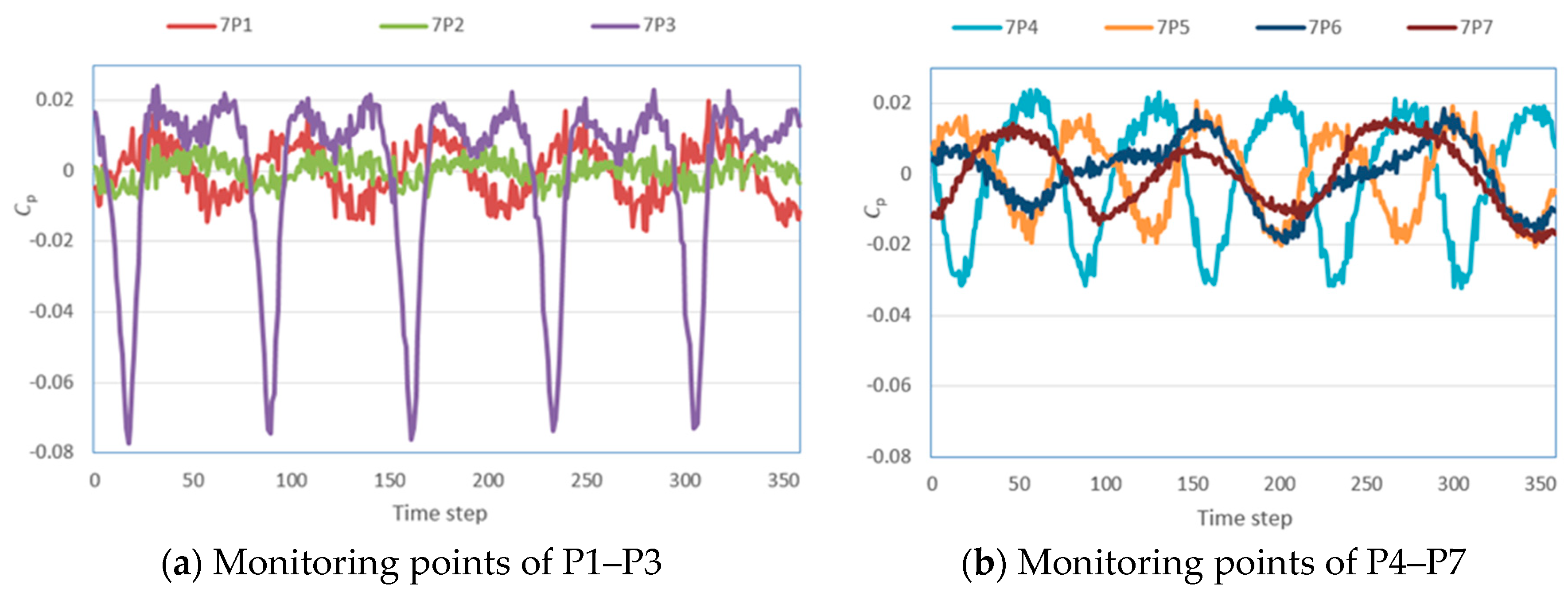
5.2. Pressure Fluctuation Analysis

In this study, the pressure coefficient is used to measure the pressure fluctuation. The pressure coefficient is defined as:
C p = p p ¯ 1 2 ρ u 2 ,
where p is the static pressure at the location of the monitoring points; u is the circumferential velocity of impeller outlet; and p ¯ is mean static pressure at the monitoring points during the rotation of the impeller. After 10 cycles of impeller rotation, the pressure fluctuations at the inlet and outlet of the impeller show the regular periodicity. In the process of the impeller rotating 360 degrees (360 time steps), the pressure fluctuation at each monitoring point was collected to analyze the unsteady flow in the flow channel.
To compare the transient pressure fluctuation characteristics in the flow channel of pump, seven monitoring points were arranged in the same position in three scenarios of space diffuser, 6P7–6P1 represents the pump flow channel of the six-vane configuration, 7P7–7P1 represents the pump flow channel of the seven-vane configuration, 8P7–8P1 represents the pump flow channel of the eight-vane configuration. The position of the seven monitoring points in the flow channel is shown in Figure 7.
Figure 8 presents the pressure fluctuation for each monitoring point in the pump flow channel of the six-vane configuration. Generally speaking, the pressure fluctuation shows stable periodicity at the impeller outlet and inlet. During the process of impeller rotating 360 degrees, five peaks and five troughs are seen, which is equal to the number of impeller blades. The pressure fluctuation amplitude at P1 located at the impeller inlet is the lowest one. The pressure fluctuation amplitude at P3 is the most intense one, which is located at the intersection of the diffuser vanes and the impeller blades. The static pressure changes along with the rotation of the impeller. In particular, when the impeller blade rotates from the pressure surface to the suction surface, the static pressure changes rapidly from the smallest value to the largest value. By comparing the amplitude of each monitoring points, we could find that the pressure fluctuation signal is generated at the impeller outlet, and in the process of its transfer to the pump outlet, its intensity gradually decays.
Figure 9 and Figure 10 show time domain diagram of pressure fluctuation at each monitoring point for the configurations of 7 vanes and 8 vanes, respectively. It can be seen that pressure fluctuation at the monitoring point in the impeller inlet (P1, P2) and the impeller outlet (P3, P4) is similar to that of the six-vane configuration, exhibiting again five peaks and five troughs. It shows that at the impeller outlet and the impeller inlet, the pressure fluctuation is mainly affected by the impeller blade number, and the diffuser vane number has no effect on the pressure fluctuation at these locations. However, after entering the diffuser vane, the pressure fluctuations at P5, P6, and P7 change with the increase of the diffuser vane number and the pulse intensity increases with the increase of the vane number. Especially for the eight-vane configuration, the pressure fluctuation amplitude at the diffuser outlet is relatively large.

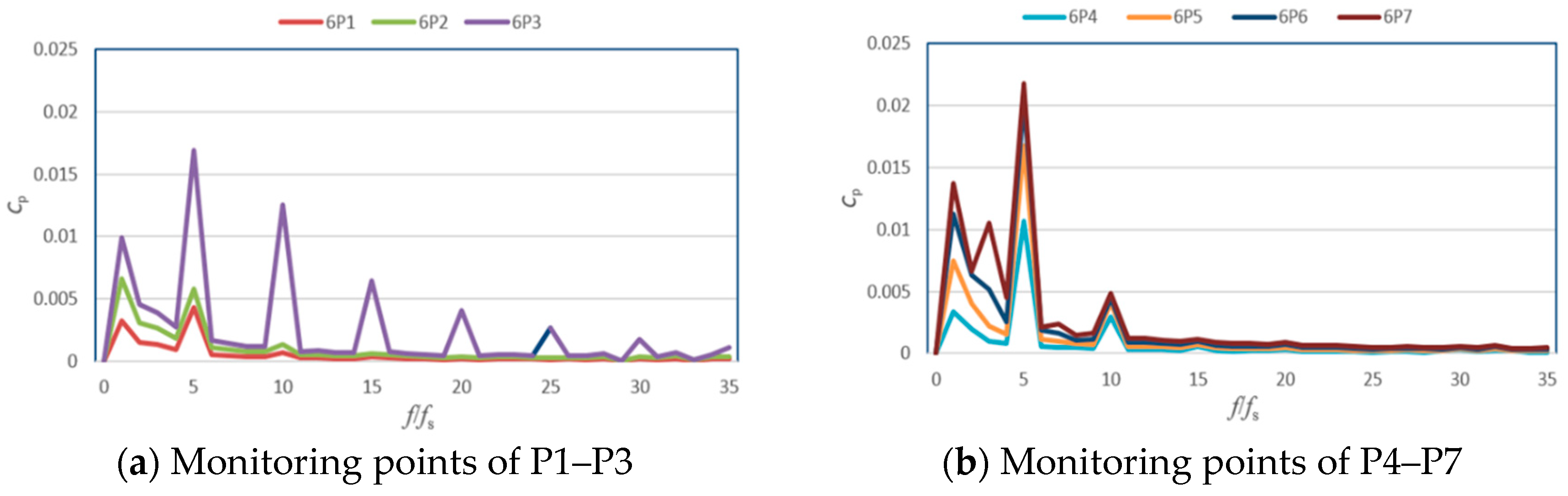
5.3. Frequency Domain Analysis

In the rotating coordinate system, the static and dynamic interference between the diffuser vanes and the impeller blades is similar to the pressure fluctuation of sinusoid and cosine waves. This transient periodic fluctuation can be decomposed into Fourier series. In this study, we used Fast Fourier Transform (FFT) to analyze the frequency domain characteristics of the pressure fluctuation between the pump stages. The fundamental frequency of the internal pressure fluctuation is generally shaft frequency (fs), so the frequency domain is analyzed by comparing with the shaft frequency fs. The frequency is divided by the fundamental frequency to get a multiple of the fundamental frequency as a horizontal coordinate. The rotating speed of the investigated pump is 2850 r/min, so the shaft frequency is 47.5 Hz.
Figure 11 presents the spectrum of pressure fluctuation at each monitoring point in the pump flow channel of the six-blade configuration. The frequency distribution at each monitoring point is basically the same, and fluctuating frequency appears at the double leaf frequency of Blade Passing Frequency (BPF, f/fs = 5) and its harmonic frequencies. It is further explained that the static and dynamic interference at the outlet of the impeller is the main cause of the pressure fluctuation, and the pressure fluctuation signal is gradually fading during the process of transferring at the inlet side of the impeller and the outlet side of the pump.
Figure 12 and Figure 13 show the spectrum of pressure fluctuation at each monitoring point in the seven-vane and eight-vane configurations, respectively. Compared to the six-vane configuration, the frequency domain characteristics of pressure fluctuation are very similar. The closer to the impeller, the greater the pressure coefficient pulsation amplitude, and the fluctuating amplitude shows an obvious tendency of obviously increasing. As the number of the diffuser vanes increases, the amplitude of pressure fluctuation at each monitoring point in the diffuser vane increases gradually, which indicates that the velocity of the fluid is converted to pressure energy by the diffuser vanes. With the increase of static pressure, the influence of BPF decays gradually, and the effect of the diffuser becomes gradually obvious. The lower number of diffuser vanes is beneficial to obtain a weak pressure fluctuation intensity.

5.4. Static Pressure Distributions

Figure 14, Figure 15 and Figure 16 compare the static pressure distribution on the same diameter section in the pump flow channel of different blade configurations. It can be seen that the static and dynamic interference between the diffuser and the impeller makes the pressure field periodically change. At the impeller outlet, the blade is no longer working on the fluid, the flow rate begins to decline, flow separation appears gradually, and two different regions appear at the pressure fields of the impeller outlet. A low-pressure area is located at the outlet of the impeller blades, while the other one is in the mainstream area downstream from the blade pressure surface, which is also known as the wake-jet, as shown in Figure 14. Wake changes gradually along with the rotating impeller, while the location of the vortex core remains unchanged, and always appears at the exit of the blades. The generation of static and dynamic interference process can be attributed to the jet and wake flow that then flows into the diffuser vanes.
As shown in Figure 15, with the increase of diffuser vane number from six to seven, the flow channel area of diffuser decreases. Accordingly, the frequency of the dynamic and static interference between impeller blades and diffuser vanes increases, and the amplitude of pressure fluctuation increases obviously. Meanwhile, Figure 16 shows that the evolution period of static pressure in the flow channels of three configurations is about 72 degrees, which is the same as the rotation period of the impeller blades. When the outlet side of impeller blade converges with the inlet side of the diffuser vanes, the rotor-stator interaction is the most intense. Simultaneously, there is an obvious low-pressure zone at the outlet of impeller blade, which is close to the pressure surface. With the rotation of the impeller, when the outlet side of the impeller blade is gradually close to the inlet side of the diffuser vanes, the low pressure zone begins to diffuse from the pressure surface of the impeller blade to the suction surface of the diffuser. Then with the interleaving between the impeller channel and the diffuser channel, wake, and jet at the impeller outlet flows into the diffuser vanes successively, the static pressure distribution in the diffuser has a periodic evolution, the area of the low pressure region also changes with the rotation of the impeller blades. When the inlet of the diffuser vanes overlaps with the outlet of impeller blade, the area of low-pressure region generated by the wake is the smallest, and the pressure fluctuation amplitude inside the diffuser is the smallest.

6. Conclusions

This paper introduces the basic theory and research methods of the pressure fluctuation, and the unsteady numerical simulation under multi-working conditions of three different configurations of a centrifugal pump corresponding to different numbers of diffuser vanes. The unsteady pressure fluctuation in the transient flow is obtained, and the frequency domain and the time domain distribution are analyzed and compared by means of Fast Fourier Transform. With the increase of the number of diffuser vanes, the amplitude of each monitoring point in the diffuser increases gradually, which indicates that the velocity of the fluid is converted to pressure due to the operation of diffuser. The lower number of diffuser vanes is beneficial to obtain the weaker pressure fluctuation intensity. It can be clearly seen that with the static pressure gradually increasing, the effects of the impeller blade passing frequency decay gradually, and the effect of the diffuser vanes increases gradually. The results could supply a basis for further design improvement of the pump body structure and working reliability.

Author Contributions

Conceptualization, L.B., L.Z. and Y.Z.; Methodology, L.Z.; Resources: W.S.; Writing-Original Draft Preparation, L.B.; Writing-Review & Editing, C.H.; Supervision, L.Z.

Funding

This research was funded by the National Natural Science Foundation of China (Grant No. 51609106 and 51805214), China Postdoctoral Science Foundation (Grant No. 2015M581737 and 2017T100331), and Jiangsu Province 333 Projects (Grant No. BRA2017353).

Conflicts of Interest

The authors declare no conflict of interest.

References

  1. Gülich, J.F. Centrifugal Pumps; Springer: Berlin/Heidelberg, Germany, 2008. [Google Scholar]
  2. Wang, C.; Shi, W.; Wang, X.; Jiang, X.; Yang, Y.; Li, W.; Zhou, L. Optimal design of multistage centrifugal pump based on the combined energy loss model and computational fluid dynamics. Appl. Energy 2017, 187, 10–26. [Google Scholar] [CrossRef]
  3. Yang, J.; Pavesi, G.; Liu, X.; Xie, T.; Liu, J. Unsteady flow characteristics regarding hump instability in the first stage of a multistage pump-turbine in pump mode. Renew. Energy 2018, 127, 377–385. [Google Scholar] [CrossRef]
  4. Iino, T.; Sato, H.; Miyashiro, H. Hydraulic axial thrust in multistage centrifugal pumps. J. Fluids Eng. 1980, 102, 64–69. [Google Scholar] [CrossRef]
  5. Xue, Z.; Cao, X.; Wang, T. Vibration test and analysis on the centrifugal pump. J. Drain. Irrig. Mach. Eng. 2018, 36, 472–477. [Google Scholar]
  6. Chen, H.; Zhang, T.; Wang, C. Structural characteristics of ultrahigh-pressure multistage centrifugal pump typed SDZ310. J. Drain. Irrig. Mach. Eng. 2018, 36, 567–572. [Google Scholar]
  7. Berten, S.; Dupont, P.; Farhat, M.; Avellan, F. Rotor-stator interaction induced pressure fluctuations: CFD and hydroacoustic simulations in the stationary components of a multistage centrifugal pump. In Proceedings of the ASME/JSME 2007 5th Joint Fluids Engineering Conference, San Diego, CA, USA, 30 July–2 August 2007; pp. 963–970. [Google Scholar]
  8. Khalifa, A.E.; Al-Qutub, A.M.; Ben-Mansour, R. Study of pressure fluctuations and induced vibration at blade-passing frequencies of a double volute pump. Arab. J. Sci. Eng. 2011, 36, 1333–1345. [Google Scholar] [CrossRef]
  9. Guelich, J.F.; Bolleter, U. Pressure pulsations in centrifugal pumps. J. Vib. Acoust. 1992, 114, 272–279. [Google Scholar] [CrossRef]
  10. Spence, R.; Amaral-Teixeira, J. A CFD parametric study of geometrical variations on the pressure pulsations and performance characteristics of a centrifugal pump. Comput. Fluids 2009, 38, 1243–1257. [Google Scholar] [CrossRef] [Green Version]
  11. Zhou, L.; Shi, W.; Bai, L.; Lu, W.; Li, W. Numerical investigation of pressure fluctuation and rotor-stator interaction in a multistage centrifugal pump. In Proceedings of the ASME 2013 Fluids Engineering Division Summer Meeting, Incline Village, NV, USA, 7–13 July 2013. [Google Scholar]
  12. Ji, P.; Yuan, S.; Li, X.; Yuan, J. Numerical prediction of 3-D periodic flow unsteadiness in a centrifugal pump under part-load condition. J. Hydrodyn. Ser. B 2014, 26, 257–263. [Google Scholar]
  13. Jiang, W.; Li, G.; Liu, P.; Fu, L. Numerical investigation of influence of the clocking effect on the unsteady pressure fluctuations and radial forces in the centrifugal pump with vaned diffuser. Int. Commun. Heat Mass Transf. 2016, 71, 164–171. [Google Scholar] [CrossRef]
  14. Wang, Z.; Qian, Z.; Lu, J.; Wu, P. Effects of flow rate and rotational speed on pressure fluctuations in a double-suction centrifugal pump. Energy 2019, 170, 212–227. [Google Scholar] [CrossRef]
  15. Posa, A.; Lippolis, A. Effect of working conditions and diffuser setting angle on pressure fluctuations within a centrifugal pump. Int. J. Heat Fluid Flow 2019, 75, 44–60. [Google Scholar] [CrossRef]
  16. Tan, L.; Zhu, B.; Wang, Y.; Cao, S.; Gui, S. Numerical study on characteristics of unsteady flow in a centrifugal pump volute at partial load condition. Eng. Comput. 2015, 32, 1549–1566. [Google Scholar] [CrossRef]
  17. Wang, L.; Tan, L.; Zhu, B.; Cao, S.; Wang, B. Numerical investigation of influence of inlet guide vanes on unsteady flow in a centrifugal pump. Proc. Inst. Mech. Eng. Part C J. Mech. Eng. Sci. 2015, 229, 3405–3416. [Google Scholar]
  18. Feng, J.; Luo, X.; Guo, P.; Wu, G. Influence of tip clearance on pressure fluctuations in an axial flow pump. J. Mech. Sci. Technol. 2016, 30, 1603–1610. [Google Scholar] [CrossRef]
  19. Alemi, H.; Nourbakhsh, S.; Raisee, M.; Raisee, M.; Najafi, A.F. Effects of volute curvature on performance of a low specific-speed centrifugal pump at design and off-design conditions. ASME J. Turbomach. 2015, 137, 041009. [Google Scholar] [CrossRef]
  20. Melzer, S.; Müller, T.; Schepeler, S.; Kalkkuhl, T.; Skoda, R. Experimental and numerical investigation of the transient characteristics and volute casing wall pressure fluctuations of a single-blade pump. Proc. Inst. Mech. Eng. Part E J. Process Mech. Eng. 2019, 233, 280–291. [Google Scholar] [CrossRef]
  21. Shibata, A.; Hiramatsu, H.; Komaki, S.; Miyagawa, K.; Maeda, M.; Kamei, S.; Hazama, R.; Sano, T.; Iino, M. Study of flow instability in off design operation of a multistage centrifugal pump. J. Mech. Sci. Technol. 2016, 30, 493–498. [Google Scholar] [CrossRef]
  22. Zhou, L.; Bai, L.; Shi, W.; Li, W.; Wang, C.; Ye, D. Numerical analysis and performance experiment of electric submersible pump with different diffuser vanes number. J. Braz. Soc. Mech. Sci. Eng. 2018, 40, 1–11. [Google Scholar] [CrossRef]
  23. Naumann, H.; Yeh, H. Lift and pressure fluctuations of a cambered airfoil under periodic gusts and applications in turbomachinery. J. Eng. Power 1973, 95, 1–10. [Google Scholar] [CrossRef]
  24. Gonzalez, J.; Fernández, J.; Blanco, E.; Santolaria, C. Numerical simulation of the dynamic effects due to impeller-volute interaction in a centrifugal pump. J. Fluids Eng. 2002, 124, 348–355. [Google Scholar] [CrossRef]
  25. Zhang, J.; Xia, S.; Ye, S.; Xu, B.; Song, W.; Zhu, S.; Xiang, J. Experimental investigation on the noise reduction of an axial piston pump using free-layer damping material treatment. Appl. Acoust. 2018, 139, 1–7. [Google Scholar] [CrossRef]
  26. Pro/ENGINEER Wildfire 5.0; Parametric Technology Corporation: Boston, MA, USA, 2008.
  27. Qian, J.Y.; Chen, M.R.; Liu, X.L.; Jin, Z.J. A numerical investigation of the flow of nanofluids through a micro Tesla valve. J. Zhejiang Univ. Sci. A 2019, 20, 50–60. [Google Scholar] [CrossRef]
  28. ANSYS ICEM CFD User Manual; ANSYS ICEM CFD 14.5; ANSYS, Inc.: Canonsburg, PA, USA, 2012.
  29. Li, X.; Gao, P.; Zhu, Z.; Li, Y. Effect of the blade loading distribution on hydrodynamic performance of a centrifugal pump with cylindrical blades. J. Mech. Sci. Technol. 2018, 32, 1161–1170. [Google Scholar] [CrossRef]
  30. Moore, J.J.; Palazzolo, A.B. Rotordynamic force prediction of whirling centrifugal impeller shroud passages using computational fluid dynamic techniques. J. Eng. Gas Turbines Power 2001, 123, 910–918. [Google Scholar] [CrossRef]
  31. ANSYS Fluent Theory Guide; Release 14.5; ANSYS, Inc.: Boston, MA, USA, 2012.
  32. Gonzalez, J.; Santolaria, C. Unsteady flow structure and global variables in a centrifugal pump. J. Fluids Eng. 2006, 128, 937–946. [Google Scholar] [CrossRef]
  33. Majidi, K. Numerical study of unsteady flow in a centrifugal pump. In Proceedings of the ASME Turbo Expo 2004: Power for Land, Sea, and Air, Vienna, Austria, 14–17 June 2004; pp. 805–814. [Google Scholar]
  34. Desbrun, M.; Gascuel, M.-P. Smoothed particles: A new paradigm for animating highly deformable bodies. In Computer Animation and Simulation’96; Springer: Vienna, Austria, 1996; pp. 61–76. [Google Scholar]
  35. Belytschko, T.; Neal, M.O. Contact-impact by the pinball algorithm with penalty and Lagrangian methods. Int. J. Numer. Methods Eng. 1991, 31, 547–572. [Google Scholar] [CrossRef]
  36. Kim, J.; Moin, P. Application of a fractional-step method to incompressible Navier-Stokes equations. J. Comput. Phys. 1985, 59, 308–323. [Google Scholar] [CrossRef]
  37. Zhang, S.; Li, X.; Zhu, Z. Numerical simulation of cryogenic cavitating flow by an extended transport-based cavitation model with thermal effects. Cryogenics 2018, 92, 98–104. [Google Scholar] [CrossRef]
  38. Zhou, L.; Bai, L.; Li, W.; Shi, W.; Wang, C. PIV validation of different turbulence models used for numerical simulation of a centrifugal pump diffuser. Eng. Comput. 2018, 35, 2–17. [Google Scholar] [CrossRef]
Figure 1. Solid model of impeller with five blades.
Processes 07 00354 g001
Figure 2. Solid model of three configurations with different diffuser vanes number.
Processes 07 00354 g002
Figure 3. Computational domain.
Processes 07 00354 g003
Figure 4. Structured mesh of the impeller and diffuser.
Processes 07 00354 g004
Figure 5. Boundary conditions.
Processes 07 00354 g005
Figure 6. Comparison of pump performance between CFD and experimental results.
Processes 07 00354 g006
Figure 7. Location of monitoring points.
Processes 07 00354 g007
Figure 8. Pressure fluctuation of the six-vane configuration.
Processes 07 00354 g008
Figure 9. Pressure fluctuation of the seven-vane configuration.
Processes 07 00354 g009
Figure 10. Pressure fluctuation of the eight-vane configuration.
Processes 07 00354 g010
Figure 11. Frequency domain analysis of the six-vane configuration.
Processes 07 00354 g011
Figure 12. Frequency domain analysis of the seven-vane configuration.
Processes 07 00354 g012
Figure 13. Frequency domain analysis of the eight-vane configuration.
Processes 07 00354 g013
Figure 14. Static pressure distribution of the six-vane configuration.
Processes 07 00354 g014
Figure 15. Static pressure distribution of the seven-vane configuration.
Processes 07 00354 g015
Figure 16. Static pressure distribution of the eight-vane configuration.
Processes 07 00354 g016
Table 1. Grid independence test.
Cases No.Grid NumberNumerical Results
ImpellerDiffuserSingle-Stage Head (m)Single-Stage
Power (kW)
Efficiency (%)
143,69562,56410.411.573964.81
2139,200316,54010.541.469770.29
3313,750509,20810.531.402173.58
4516,780937,44010.561.403373.77
5950,8951,297,38010.571.404273.74

