Abstract
Spiral nozzles are widely used in wet scrubbers to form an appropriate spray pattern to capture the polluting gas/particulate matterwith the highest possible efficiency. Despite this fact, and a fact that it is a nozzle with a very atypical spray pattern (a full cone consisting of three concentric hollow cones), very limited amount of studies have been done so far on characterization of this type of nozzle. This work reports preliminary results on the spray characteristics of a spiral nozzle used for gas absorption processes. First, we experimentally measured the pressure impact footprint of the spray generated. Then effective spray angles were evaluated from the photographs of the spray and using the pressure impact footprint records via Archimedean spiral equation. Using the classical photography, areas of primary and secondary atomization were determined together with the droplet size distribution, which were further approximated using selected distribution functions. Radial and tangential spray velocity of droplets were assessed using the laser Doppler anemometry. The results show atypical behavior compared to different types of nozzles. In the investigated measurement range, the droplet-size distribution showed higher droplet diameters (about 1 mm) compared to, for example, air assisted atomizers. It was similar for the radial velocity, which was conversely lower (max velocity of about 8 m/s) compared to, for example, effervescent atomizers, which can produce droplets with a velocity of tens to hundreds m/s. On the contrary, spray angle ranged from 58° and 111° for the inner small and large cone, respectively, to 152° for the upper cone, and in the measured range was independent of the inlet pressure of liquid at the nozzle orifice.
1. Introduction
Gas–liquid absorption processes for gaseous contaminants removal are crucial in diverse industrial fields and are basic means for air pollution mitigation associated with large-scale industrial operations. To ensure the reduction of the gaseous pollutants released from such processes, many industrial facilities adopt a gas scrubbing system as a post-treatment of produced polluted air. Gas scrubbers are rather complicated devices, in which the polluted air is cleaned using a sprayed liquid, mostly various aqueous solutions depending on the gas to be removed. This includes, for example, CO2 and VOC removal [1,2,3], flue gas desulphurization [4,5,6], and ammonia separation [7]. Last but not least, scrubbing systems have widely been recognized in separation of particulate matter [8,9,10,11,12], the release of which is due mostly to various combustion processes [13,14,15] and, for example, comminution technologies [16,17]. This is very important due to associated health and environmental concerns [18,19]. Comparing the ability to remove particulate and gaseous pollutants, gas scrubbers have lower efficiency in one cleaning cycle but are able to treat a significantly higher amount of polluted air compared to, for example, air filtration or membrane contactors [20,21,22,23]. In these applications, filter/membrane causes additional resistance to airflow, thus disabling processing of huge amounts of polluted air generated in large-scale industrial processes. On the other hand, gas scrubbers work with sprayed absorption liquid media, which must then be subjected to another processing step, such as regeneration (if possible) or disposal, which can be very expensive and energy demanding [24]. Due to these facts, there is a large field for development and optimization of these systems in terms of operational parameters, chemicals used or spraying arrangement including usage of extremely broad spectrum of nozzles. Nozzles are crucial in a plethora of industrial applications including dust control [25], spray cooling [26,27,28,29,30], hydraulic descaling [31], and play a vital role in gas scrubbers as they can provide an adequate spray pattern of the absorption liquid. This is necessary to create the largest possible contact surface with gas phase to ensure process intensification, appropriate mass transfer and thus separation efficiency. Such a type of nozzle, which has scarcely been studied in terms of the spray characteristics, is the spiral nozzle.
Spiral nozzles have been found in different applications including flue gas desulfurization and spray towers [4,5,32], spray drying [33], distillation [34], petrochemical industry [35], and fire suppression [36,37]. Several studies tried to focus on the basic spray characteristics including droplet-size distribution, the inlet liquid pressure–flowrate relationship, and mass spray density [38,39,40,41] at different hydrodynamic conditions. Some authors did a research on the spray surface geometry [42] and even air-assisted atomization using the spiral nozzle [43]. Important works related to the present study are further described in detail. Li et al. [4] investigated spray characteristics of spiral nozzles used in flue gas desulfurization. They observed the flowrate was linear with a square root of pressure and droplet diameter was a power function of pressure. The droplet diameter variations with pressure were similar for spiral nozzles with different orifice, while the spray angle varied slightly at pressures higher than 40 kPa. Zhang et al. [32] studied spray characteristics of spiral nozzles with different diameters using particle image velocimetry at different spray pressures. They observed both, the spray pressure and nozzle diameter, to have an influence on the spray angle, droplet diameter, droplet size uniformity, and sprayed area diameter. In a biomass pyrolysis experiments, they found a nozzle with a diameter of 5.6 mm and the liquid pressure of two bars to be ideal for the quenching of pyrolysis vapors. In another study, Zhou et al. [41] conducted experiments on the flow distribution characteristics of a low-pressure high-flux spiral nozzle using a flow distribution testing system. They analyzed the effect of nozzle size on the flow distribution by varying several parameters including nozzle dimensions (nozzle length to diameter ratio), radial flowrate, position of sprayed surface, and spraying angle. The results indicated that with increasing nozzle length to diameter ratio, the flowrate decreases and spraying angle increases. With increasing pressure, the relationships were the same as in the above mentioned works. Dong et al. [5] compared desulfurization performance of scrubbers with spiral and Dynawave nozzle. Li et al. [42] developed a spray surface geometry model of a spiral nozzle with involute atomization. They further simulated the model using MATLAB, which validated its effectiveness and provided a theoretical basis for designing and manufacturing the spiral nozzles. Wasik et al. [38] studied the influence of nozzle type (including a TF6 spiral nozzle) on a mass spray density. For other works on spiral nozzles, especially those with different application, refer to [33,34,35].
In this study, we focus on a spiral nozzle (Figure 1a), which generates an atypical cone-like spray consisting of three concentric hollow cones (Figure 1b), thus creating a full cone pattern (for further details refer to [44]). The pattern is formed via a complicated nozzle geometry without axis of symmetry and gradually narrowing orifice, in which the liquid is sprayed from several rebound surfaces at different rake angles. This nozzle is quite different compared to spiral channel nozzles [45] or spiral flow nozzles [46,47] with which it can be confused. Generally, a lot of works have been carried out on nozzles creating a full-cone spray in various application fields [48,49,50,51,52,53,54,55,56,57,58]. Conversely, the amount of works on nozzles with a spiral geometry is quite limited despite the fact that they possess several very interesting features [59]:
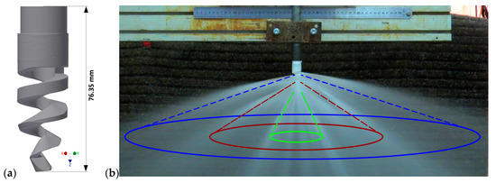
Figure 1.
A 3D model of the spiral nozzle studied (a) and the concentric hollow cone pattern produced by the nozzle (b).
- They are made of one piece of material (no internal parts, hence resistant to clogging);
- They have high discharge coefficients (higher flowrates possible at lower pressure drops);
- They can provide fine atomization, wide range of flowrates and spray angles;
- A reduction in waste energy appearing as noise;
- Very wide effective patterns produced allow replacing several nozzles with one.
Therefore, we investigate the pressure impact footprint of the falling liquid (cross-sectional pattern of the spray), spray radial, and tangential velocity distribution using the laser Doppler anemometry (LDA). The pressure impact footprint of the spray is generally important in spray cooling applications; in gas absorption processes this is not typically used. However, this can be easily used for validation of CFD data, as it is practically simpler to measure pressure impact compared to using the LDA method which is not always available. Further, we aimed at the spray morphology. This involved droplet-size distribution, spray angle, and determining the area of primary and secondary breakup of the spray using a classical photography modified with an Nd:YAG (neodymium-doped yttrium aluminum garnet) pulse laser, and assess the breakup areas using selected dimensionless numbers, which has not been carried out before for similar type of nozzle. We also compared the droplet diameter with selected theoretical relationships used for prediction of droplet and ligament diameter. Finally, we tried to outline flow conditions for ideal nozzle operation.
2. Underlying Phenomena
Liquid atomization (i.e., a breakup of liquid jet into dispersed fine droplets) is a complex process involving several physical/chemical phenomena that take place simultaneously. The spray characteristics (e.g., morphology, droplet size distribution, etc.) are strongly dependent on the atomizer used, especially on its size and geometry. Further, it is dependent on the physical properties of the fluids involved (i.e., the atomized liquid and the environment into which the liquid is sprayed (usually ambient air)). The spray atomization is strongly influenced by the liquid density, viscosity, and surface tension. The effect of density is rather lower, as indicated by the experimental data [60]. Conversely, the influence of the surface tension is quite essential. Surface tension is a force acting against the formation of a new surface area. Atomization involves two main phases (i.e., primary and secondary atomization). In the primary atomization, the disruptive forces act against the consolidating forces and cause oscillations of the liquid. Once the disruptive forces are stronger than the consolidating ones (surface tension), the bulk liquid disintegrates into smaller formations (ligaments, larger drops). Then the secondary atomization occurs (i.e., larger droplets or ligaments split into smaller droplets in a gas caused by either greater relative velocity or turbulence) [61]. A governing parameter relating disruptive inertial and restorative surface tension forces is the non-dimensional Weber number:
where ρ, v, d, and σ are the fluid density, absolute radial velocity of liquid, characteristic dimension, and surface tension, respectively. The larger the Weber number, the higher the tendency toward the liquid breakup [62]. Viscosity is another very important parameter affecting the droplet size distribution and mainly the flow mode inside the atomizer, thus influencing the spray pattern/morphology. The influence of viscosity on the flow in the nozzle is quite complex and depends on the type of atomizer. Generally, drop size increases with increasing viscosity and delays the liquid jet breakup [60]. Both surface tension and viscosity decrease the tendency of the jet/sheet to disintegrate, which is accounted for by the Ohnesorge number (i.e., the ratio of viscous to surface tension forces):
where ρl and µl are the liquid density and viscosity, respectively. Many spray nozzles form a liquid sheet from bulk liquid prior to the atomization itself. The liquid sheet exits the nozzle orifice and may oscillate, which results in the formation of liquid ligaments, which are then broken into droplets. The droplet size is mostly in the same order as the liquid sheet thickness [63]. The primary atomization is strongly dependent on the liquid jet Weber number:
where do is the nozzle orifice diameter and νjet is the jet velocity (i.e., liquid velocity inside the nozzle prior to exiting the orifice). If the jet Weber number is lower, the surface tension forces impede the formation of a new surface area, thus preventing the liquid sheet breakup. Conversely at a larger jet Weber number, the breakup occurs due to the inertial forces to completely dominate over the surface tension forces causing the liquid sheet to tear into ligaments and droplets [64]. A critical value of the jet Weber number describes the onset of a decrease of the radial breakup distance. This value is typically around 1000 depending on the nozzle type [65]. After the first breakup phase, the secondary atomization may occur which is indicated by the gas Weber number:
where ρg is the ambient gas density. Droplet viscous forces are significant for Oh > 0.1. For Oh below this value, the breakup was observed to be independent of Oh. For Oh < 0.1, the transition We for individual breakup modes were practically constant as reported previously [66,67,68]. The individual modes are droplet deformation/vibrational breakup for 0 < We < 11, bag breakup for 11 < We < 35, multimode breakup for 35 < We < 80, sheet thinning for 80 < We < 350, and catastrophic breakup for We > 350. These are; however, not valid for conditions with higher Oh. The individual modes of secondary atomization are often depicted in We-Oh space, refer, for example, to [68,69,70,71]. To assess objectively which regime factually took place in the atomization process, several correlations for critical Weber number (Wec) were proposed for Oh → 0. One of such correlation was suggested for Oh < 4 by Gelfand [72] as follows:
where WecOh→0 is the critical We at low Oh, as listed above for individual modes.
The liquid sheet is formed via impinging the edge layer of the liquid jet on the surface of the helix as indicated in the CFD model (Figure 2). Therefore, we can expect an analogy with the radial spread of a liquid jet over a horizontal plane. This can be used to estimate the liquid sheet thickness (tsh) based on the free-surface similarity boundary layer concept as developed by Watson [73] and used by Ren et al. [74] and Zhou and Yu [75]. Assuming the sheet flow on the helix surface be turbulent, the sheet thickness at the edge of the helix can be estimated as follows:
where do and rh are the nozzle orifice diameter (11.25 mm) and width of the helix (6.45 mm), respectively, and Re is the Reynolds number at the nozzle orifice calculated as follows:
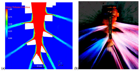
Figure 2.
A CFD model illustration of the formation of the liquid sheet by impinging the peripheral jet layer onto the surface of the helix (a) and a photograph of the same with the applied screen filter (b).
To estimate the spray velocity in a given radial location (r), it is necessary to consider the effect of viscous interaction with the helix surface. Therefore, a non-dimensional sheet thickness is defined as the ratio of the actual thickness (tsh) to an inviscid sheet thickness (tsh0):
Note that tsh0 is the first term in Equation (6). The average sheet velocity at the edge of the helix can be calculated as [74]:
where K is the flow factor, which is a characteristic constant of the nozzle and ∆p is the pressure drop at the nozzle (inlet pressure of the liquid). There is a relationship between the volumetric flowrate (QV) and the inlet water pressure (∆p) as follows:
For the spiral nozzle used in this study, the value is about 75. Further breakup of the sheet into ligaments and droplets is due to inherent instabilities caused by the wave growth. The wavelength at the sheet breakup governs the size of the ligaments and ultimately the droplet diameter. Dombrowski and Johns [76] developed a theory to predict the wave instability of liquid sheets in an inviscid gas. The model assumes sinusoidal waves to be on the liquid sheet, and the force balance is performed considering the inertial, pressure, and surface tension forces be associated with the wave displacement. After simplification, the force balance can be expressed as follows:
where τ is time and f and are the breakup parameter and wavenumber, respectively. The breakup parameter, also called dimensionless wave amplitude, was first investigated by Weber [77] who obtained a value of 12 and further confirmed by Dombrowski and Hooper [78] who stated that this value is constant regardless of the experimental conditions. However, in this study we better used the following correlation as it can be a function of the nozzle geometry [63]:
where the Weber and Reynolds numbers are calculated for jet (i.e., liquid properties), liquid jet velocity prior to entering the nozzle orifice, and nozzle orifice diameter as the characteristic length. Another attempt was to estimate theoretically the ligament and droplet sizes based on the wave instabilities, which are the main cause of sheet disintegration. With an assumption of attenuating sheet and the formed ligaments be of cylindrical shape, the diameter estimate can be expressed as follows [76]:
where k for a uniform velocity radiating sheet can be expressed as follows:
Accordingly, the estimate of the ligament breakup time τL,bu can be written as follows [74,77,79]:
Based on the ligament size dL, the droplet diameter dD can be calculated [76,77]:
where Ohsh is the Ohnesorge number based on the sheet thickness.
3. Experimental
3.1. Spiral Nozzle
A TF-28 150 asymmetric spiral nozzle (BETE, USA) was used in this study. Figure 3 shows a 3D scan of the nozzle obtained using an ATOS Tripple Scan 8M camera and its profile. The nozzle is made of Teflon and has a narrowing spiral-like orifice. The spiral is divided into three sections based on the rake angle of the rebound surfaces related to the nozzle Z-axis. Liquid falling on the individual rebound surfaces of the helix forms a full cone. The full cone can be considered for a combination of three water curtains in the form of hollow concentric cones (Figure 1 and Figure 4). Based on their position to each other, they can be called as the outer (upper) cone, inner large, cone and inner small cone, as indicated in Figure 4a.
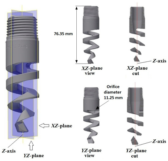
Figure 3.
The BETE TF-28 150 spiral nozzle with designation of the longitudinal axis (Z-axis), views from different planes, and longitudinal cross sections (plane cuts).
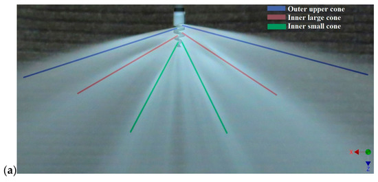
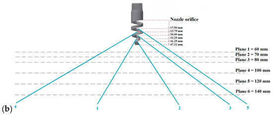
Figure 4.
An illustration of the main streams of the spray generated (a) and a depiction of the sprayed water beams numbered (blue); the distances of the beginning of the water beams from the nozzle orifice and the distances of individual impact planes from the nozzle orifice (b).
3.2. Pressure Impact Footprint
Measurement of the pressure impact footprint was done to visualize the pressure patterns generated by the sprayed water. During spraying the water curtain fell down on surface connected to an electronic tensometric pressure sensor. This surface was placed on a position system, which was operated using a computer software. The real impact pressure values were recorded depending the sensor position related to the nozzle. The impact measurement was performed twice, each with a different arrangement of the impact surface. In each experiment, different hydrodynamic conditions and different distances of the nozzle from the impact surface (planes, Figure 4b) were adopted.
3.2.1. Measuring the Impact Pressure in Four Planes
In the first set, pressure impact footprint of the water curtain was measured. This was done in five planes (Figure 4b) (i.e., in the distances of 60, 80, 100, and 140 mm from the nozzle orifice). In each experiment, an inlet water pressure was 2 bars corresponding to a flowrate of 1.76 L/s. These are optimal hydrodynamic conditions for the operation of the nozzle tested. The experimental setup is shown in Figure 5. It was a metal plate (1) placed on an upper moving arm (5), in the middle of which was a dismountable metal casing (2) with a bevel-like top. At the top of the casing, an impact surface (3) was attached and connected to a tensometric pressure sensor placed inside the casing. The impact surface was circular with a diameter of 12 mm. The water falling down on the impact surface generates an impact pressure, which is taken by the sensor and the signal is recorded by the data acquisition system. The upper arm (5) was moved using a step motor in the direction of X-axis (Figure 5). This system was placed on the top of a bottom moving arm (6), which was moving in the direction of Y-axis (Figure 5). The area under the nozzle (4) was scanned in a length of 300 mm in the X-direction and 600 mm in the Y-direction, which was the maximum possible range of the experimental device used. The shift of both arms was set to 5 mm.
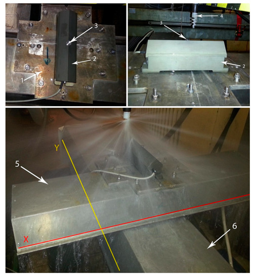
Figure 5.
Experimental setup for the impact measurement: Bed plate (1), metal casing (2), impact surface (3), spiral nozzle (4), upper movable arm (5), lower movable arm (6).
3.2.2. Measuring the Impact Pressure in One Plane at Different Water Inlet Pressures
These experiments (Figure 6) were performed to clarify the effect of different inlet water pressures (the pressure of water measured prior to entering the nozzle orifice) on the impact footprint. The impact surface (2) was in the form of a circular plate with a diameter of 200 mm, in the center of which was an opening (3) with a diameter of 1 mm. The opening was connected to a closed space under the plate where the tensometric pressure sensor was placed (4). The space was completely filled up with water prior to the measurement to ensure the impact pressure be transferred to the sensor through the water fluctuations. The remaining parts of the experimental setup including the moving arms in the X and Y axes were identical with the previous measurements (Figure 5). The only difference was the extent of the area scanned, which was 240 mm in both directions with a step of 3 mm. All the measurements were performed for plane 2 (i.e., in a distance of 70 mm from the nozzle orifice; Figure 4b). The hydrodynamic conditions are shown in Table 1.
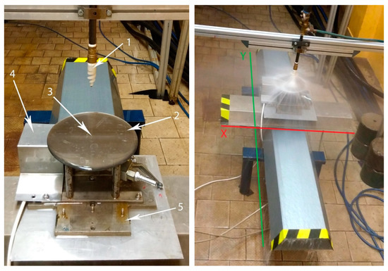
Figure 6.
Experimental setup for the impact measurement with different water inlet pressures: Spiral nozzle (1), impact surface (2), pressure sensor opening (3), pressure sensor covering (4), bed plate of the impact surface (5).

Table 1.
Experimental conditions at pressure impact measurement.
3.3. Spray Morphology
Spray morphology was observed inside a transparent laboratory-scale sprinkle chamber made of PVC glass (Figure 7a). The chamber with a water reservoir were fixed on a frame (Figure 7b) together with a centrifugal pump providing water circulation through the nozzle. The experiments were performed at 20 °C and an inlet pressure of 0.9 bar corresponding to a flowrate of 1.19 L/s. This flowrate was selected due to ideal properties of the spray for measuring in the experimental device due mainly to the size of the transparent chamber. Lower flowrate caused improper spray properties including very narrow span and practically no breakup of the liquid stream exiting the nozzle into ligaments/droplets. Higher flowrate caused significant rebound of the liquid stream from the chamber wall, which had a negative effect on the snapshots taking.
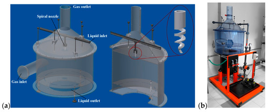
Figure 7.
A 3D model of the laboratory sprinkle chamber (a) and a real view of the same (b).
For a detailed evaluation of the spray, an apparatus as shown in Figure 8 was used (for the real view refer to supplementary Figure S1). A classical photography with a modified type of lightning (i.e., an Nd:YAG pulse laser lightning (2) with a pulse length of 5 ns) was used (a spray snapshot using classical photography and modified with laser is shown in Figure S2). The images were taken using a Canon D70 camera (1) with a Canon EF 10 mm f/2.8 USM Macro objective. From the images, the areas of primary and secondary atomization of the spray were observed. The images were further used to measure droplet size using the Stream Motion software (Olympus Corporation, Shinjuku, Japan).
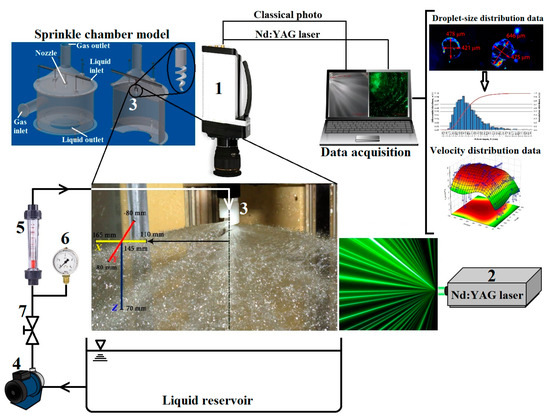
Figure 8.
A scheme of the experimental setup for the assessment of the spray morphology/kinetics with the Canon D70 camera (1), Nd:YAG pulse laser (2), spiral nozzle (3), centrifugal pump (4), flowmeter (5), manometer (6), and valve (7).
From the measured droplet sizes, distribution curves were plotted and fitted with suitable distribution functions. The appropriateness of the fitting was then tested using the Kolmogorov–Smirnov test at a significance level of 0.05. Two density distribution functions, which are frequently used to describe droplet size in sprays were chosen (i.e., log-normal and Rosin-Rammler distribution) [80]. Log-normal density distribution can be expressed as follows:
where Di, µD, and σD are the droplet diameter, mean, and standard deviation of the distribution, respectively. Rosin-Rammler density distribution is described by the following equation:
where α and β are empirical constants of the distribution. Further representative means of the droplet size were calculated (i.e., surface-weighted mean), which is used in the area of absorption processes where interphase area between two phases is important:
In addition, it is widely used Sauter mean diameter, which characterizes the spray fineness and is often used to calculate the efficiency and rate of mass transport in chemical reactions. It is a ratio of droplet volume to its surface area:
Finally, volume weighted mean was calculated as follows:
Another parameter studied was the spray angle, which was assessed using two methods. The first method was based on the pressure impact footprint curves, which were approximated using an Archimedean spiral. The other method was based on a visualization of the liquid spray in an open space to determine the spraying angle of individual cones using the Stream Motion software. Both methods are further explained in detail in the Results and Discussion section.
3.4. Spray Kinetics
Another method used was the laser Doppler anemometry (LDA), which provided us with information about the spray velocity distribution. The LDA setup was arranged on the same apparatus as for the experiments for the spray morphology evaluation (Figure 8). Thus, we obtained radial and tangential velocities from the upper and inner large cone. The LDA was performed for eight horizontal planes (Figure 9). In each plane, the spray velocity was measured in two perpendicular axes (the X-axis in yellow, and the Y-axis in red).
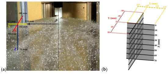
Figure 9.
A representation of the measured position in relation to the spray (a) with a detailed demonstration/description of the measured positions (b).
The beginning of the spray velocity measurement in the X-axis was at a distance of 110 mm from the nozzle center, as shown in Figure 9a (first position). Then, the spray velocity was measured after each 5 mm up to a distance of 165 mm from the nozzle center (12 positions in total). The spray velocity in the Y-axis was measured in a distance of 145 mm from the nozzle center and ranged from −80 to 80 mm (Figure 9a, detail shown in Figure 9b) perpendicular to the X-axis (33 positions in total). In each position, the measurement took 30 s or 30 thousand samples was taken. In the Z-axis, the point 0 mm corresponds to the position above the spray. The radial velocity was then measured up to 70 mm from this point in a step of 10 mm (8 positions in total; Figure 9b).
4. Results and Discussion
4.1. Pressure Impact Footprint
Data from measurements in individual planes are presented in Figure 10. In the 3D graphs of Figure 10, the axes are not equidistant and the 2D graphs show the Cartesian coordinate system from the view above, turned according to the nozzle position in the experiments. Therefore, the 2D graphs can be considered for the spray cones’ baselines and serve mainly as a visualization of the spray impact footprint of the two inner cones (the upper cone was out of the scanned area). The values of the impact pressure are very low (0.61 kPa at the highest). The reason for this is the size of the impact area, which is quite large for such a fine spray. The pressure impact intensity decreases with increasing distance from the nozzle orifice from about 0.61 kPa in the plane 1 to less than half (0.28 kPa) in the plane 6, which corresponds to the distances of individual planes from the orifice (60 and 140 mm of the plane 1 and 6, respectively). The effective spraying angle of the inner cones was further evaluated. This was done only for the pressure of 2 bars because with increasing inlet pressure, the effective spraying angle varied very slightly. Figure 10d shows the maximum impact pressure in relation to set inlet pressure of the liquid at the nozzle. We can see a linear increase up to an inlet pressure of 1.5 bar, then the impact pressure increase slowed down. The same is shown in supplementary Figure S3, which compares the varying intensity of the impact pressure at a distance of 70 mm (plane 2) from the nozzle in relation to changing increasing inlet pressure.
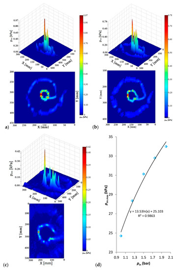
Figure 10.
Pressure distribution pattern of the sprayed liquid measured in the plane 1 (a), 3 (b), 6 (c), and a relationship between maximum impact pressure and inlet pressure of liquid at nozzle (d).
4.2. Spray Angle
The base of the inner cones can be expressed using the parametric equation of the Archimedean spiral as follows:
where x and y are the points of the curve in the coordinate system, a is the parameter, Sx and Sy are the shifted centers of the spirals, and θ is the angle between half line describing the spiral trajectory and polar axis of the system. The values of the parameter a for the inner cones are shown in (Table S1). An example of the expression for plane 3 (Figure 11a) is for the small cone as follows:
In addition, for the large cone:
where for each plane θ ∈ (2.95π; 4.95π). The upper cone could not be evaluated using this method due to its large extent and was obtained using another method as explained further. The spiral curves delineate the trajectory of the impact footprint and well corresponds to experimental data (Figure 11a). An exception can be found in the fourth quadrant (beam number 5, Figure 11a). This is due to the nozzle geometry and transition between individual cones resulting in a local change of liquid flow.
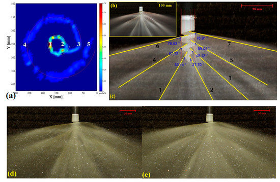
Figure 11.
Pressure impact footprint with numbered water jets (individual numbers relates to individual water beams, refer to Figure 4b) and a graphical depiction of the spirals tracing the cones’ baselines used for spraying angle assessment (in plane 3) (a), a photograph of the spray with an image filter applied to determine the main liquid streams (b), a visualization of the spray with assessment of inner angles formed by the liquid beam and nozzle longitudinal axis (c), and comparison of the spray formed at an inlet liquid pressure of 1 bar (d) and 2 bars (e).
The extent of the small cone angle was calculated as a sum of the inner angles of the beams no. 1 and 2 (refer to Figure 11a). The extent of the large cone was a sum of the beam no. 4 and an arithmetic average of beams no. 3 and 5. The inner angles of individual water beams were determined in relation to the nozzle longitudinal axis (the Z-axis) in the same position as in experiments (i.e., in the XZ plane (refer to Figure 3)). Based on the extent of water beams of both cones, the effective spraying angle γef was calculated. The average values of effective spraying angle were 61.7° and 115.5° for small and large cone, respectively, (for detailed results, refer to Table S2).
Another method to determine the spraying angle was using the photographs of the spray with applied screen filters to assess the main liquid beams (Figure 11b) and comparing with the photographs of the nozzle without spray (Figure 11c). Evaluation of the angles was done in the Stream Motion software (refer to Table S3). The small, large, and upper cone angles were 58.0°, 111.4°, and 152.3°, respectively. Comparing the results of the angles for the small and large cone with those obtained with the previous method (Table S2), we get values, which are smaller by 6% and 3.5%, respectively. This difference is mainly caused by a subjective assessment of the 2D photograph of a 3D spray, which may bring an error into the determination of the spraying angle. Both discrepancies are; however, very small and can be neglected.
Comparing the results of the spray angle with other studies, one significant difference can be observed (i.e., an independence of the spray angle on the inlet pressure (flowrate) of the liquid; Figure 11d,e), refer also to (Figure S4). This is in agreement with a previous study on characterization of a spiral nozzle, in which authors observed minimal variation of the spray angle at pressures above 0.4 bar [4]. On the contrary, such behavior is quite different compared, for example, to an air–water impinging jet atomizer [81], in which the spray angle increased with increasing pressure, or pressure swirl atomizer, in which the spray angle increased up to 7 bar and then decreased [82]. Some researchers also observed a decrease in spray angle with increasing inlet pressure in the whole measured range [48]. Another typical feature of the nozzle studied is its large spray angle, thus large spray coverage. This can be observed in nozzles mostly used for fire suppression applications [36]. However, this property is also required in the applications related to gas cleaning via absorption processes, especially for gas scrubbers with larger spray tower diameter.
4.3. Spray Breakup
Here we discuss the breakup of the outer upper cone only (Figure 4a). The other two inner cones are not evaluated as it was not allowed by the experimental setup. Moreover, the results are compared with mathematical models assuming the analogy with radial spread of a liquid jet over a horizontal plane. The condition of the horizontal plane is fulfilled for the upper cone only (Figure 2), which is formed by impinging the liquid jet on the first twist of the helix, which is horizontal (refer to CFD model at cross-section, Figure 2). The other helix surfaces (second and third twist) have different rake angles and are not horizontal, so the model could not be applied to these.
Individual atomization phases can be observed in the pictures (Figure 12) (i.e., primary/secondary atomization in various distances from the nozzle). The water sheet remains continuous up to a distance of about 80 mm (Figure 12a), even though some local perforations can be observed. Some perforations can be observed throughout the whole length of the liquid sheet (Figure 12b 2). The jet Weber number was higher than 22,000, which is far higher than the critical value of 1000 proposed by other researchers [65,83]. At this Weber number, we can expect very short radial breakup distance and the sheet to thin rapidly. The sheet thickness was estimated using the Equation (6) to be 2.47 mm at the edge of the helix and gradually decreased with increasing radial distance from the nozzle. At a distance of 78 mm, corresponding to the first sheet breakup into ligaments, the sheet thickness was estimated to 0.33 mm. The estimated sheet thickness also decreased with increasing liquid flowrate. At a radial distance of about 80 mm the sheet integrity is markedly disturbed (i.e., a primary atomization occurs up to 125 mm forming larger ligament structures; Figure 12b 1). The first ligaments observed (at the distance of 78 mm) were as large as (1.86 ± 0.57) mm with a breakup time estimate of 10.9 ms (according to Equation (15)) and attenuating down to (0.75 ± 0.19) mm with a breakup time of 2.8 ms (at a distance of approximately 120 mm). The estimate of the ligament diameter was 0.70 mm (based on Equation (13) using the correlation in Equation (12) for the dimensionless wave amplitude, at a radial distance of 120 mm). However, conducting experiments at different flowrates is necessary to assess further this comparison.
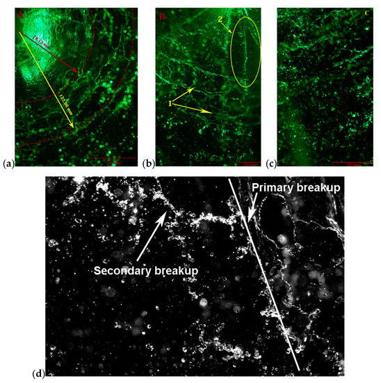
Figure 12.
Individual phases of spray atomization (a), primary spray atomization to ligaments, 1–forming of ligaments, 2–liquid sheet rupture (b) and secondary atomization to individual droplets (c), and a detail of the boundary of both phases (d).
Subsequently a breakup to individual droplets (Figure 12c) occurred in a very narrow area. From this area the droplet-size distribution and structure has changed very slightly indicating area of secondary (or better quasi-secondary) atomization of the spray. A detail of the boundary between primary (sheet breakup into ligaments) and the quasi-secondary atomization of the spray (ligaments breaking into droplets) is shown in a modified photograph (Figure 12d). Generally, similar qualitative spray characteristics were very scarcely found in the literature. Qualitatively the most similar sprays were observed in studies focusing on characterization of fire sprinklers, refer, for example, to [64,74,75,84,85]. These sprinklers consist of a convergent nozzle with a cone-disc deflector placed under in a defined distance to create a circular liquid sheet. This is very similar to the spray generated by the spiral nozzle as the principle of forming the liquid sheet is practically the same (i.e., a rebound from a surface into the ambient space).
The gas Weber number calculated for the measured droplet sizes and radial velocities was always lower than 11. This may indicate, according to some studies, no secondary breakup [86,87,88], droplet deformation [67], or vibrational breakup [66]. The latter two may be true as indicated in obtained photographs (Figure 12d, also refer to an example shown in Figure S5). This is; however, a mere qualitative observation of the spray. As the liquid is sprayed into a quiescent air, it is more probable that the secondary atomization did not occur at the adopted experimental conditions. It is also important to say that the Weber number ranges defining individual secondary breakup modes were mostly derived for liquid jets. In liquid sheets or even conical sheets, the situation can be different and is rather a suggestion for future research. In general, vibrational breakup is not always observed. Oscillations at a natural frequency of the drop are typical and a formation of only a few fragments with comparable sizes as the original droplet are observable at this mode [68].
4.4. Droplet Size Distribution
Droplet size distribution was obtained from the modified classical photography of the upper cone in various distances normal to the nozzle axis. From detailed photographs of the secondary atomization area, droplet size was measured using the Stream Motion software. Prior to the measurement, a filter was applied to the photographs to better recognize the droplet edges. Spherical droplets’ diameter was measured once, whereas the diameter of droplets of non-spherical shape was measured twice (two diameters normal to each other, refer to Figure S6), and then an arithmetic average was calculated. Using this method, 1773 droplets’ diameters were evaluated. Droplet-size distribution curves were then plotted using the obtained data (Figure 13). The width of one size class was 0.07 mm. This was obtained by dividing the whole distribution width by square root of the number of measured droplet sizes. The agreement between experimental and theoretical distribution was assessed using the Kolmogorov–Smirnov test, which revealed the best fit only for the log-normal distribution for which the P-values were higher than the selected significance level of 0.05 (refer to Table S4).

Figure 13.
Number (a), surface (b), and volume weighted (c) droplet-size distribution fitted with selected theoretical distribution functions.
Droplet-size distribution of a spray can be considered monodisperse if the standard deviation is approximately less than 10% of the mean particle diameter [80]:
In our case, according to the number droplet-size distribution of the spray, the ratio is as high as 0.48, confirming a polydisperse spray. The average droplet size was 0.815 mm, while the mode was around 0.587 mm with a portion of 8.7%. The surface-weighted average (D20) was 0.997 mm and the Sauter mean diameter (D32) was 1.201 mm. The largest amount of droplet surface (6.6%) was represented by a droplet diameter of 0.911 mm. For the volume-weighted distribution, the mean value is shifted to larger droplet diameters as large as 1.423 mm and a mode of 1.108 mm representing 5.8% of the liquid volume. The theoretical predictions of the droplet diameter were based on the theory of the liquid sheet instability, assuming an analogy with a rebound of liquid jet from a horizontal plane. A droplet diameter of 1.413 mm was calculated based on Equation (16), which is quite different from the average value obtained experimentally (0.815 mm), despite the expected analogy with the theory adopted for the diameter estimate. It is; therefore, necessary to conduct further research in this area as the description of conical sheets breakup mechanisms is rather scarce in the literature [89]. The measured droplet diameters are mostly much larger compared to different types of atomizers, which produce droplets in the range up to 100–150 µm in diameter, refer to, for example, [58,90,91,92,93], but in a similar order as compared to fire sprinklers [64,79,94]. Comparing the Sauter mean diameter empirical formulas developed for different atomizers we can also see rather significant differences. For example, the Sauter mean diameter for pressure-atomized sprays is a function of several parameters, as proposed in the correlation by Elkotb [95]:
where ∆p is the pressure drop at the nozzle (i.e., the pressure difference between pressure inside the nozzle and the ambient pressure of the space, into which the liquid is sprayed). This formula gives the Sauter mean diameter as large as 1.844 mm, which is more than 0.6 mm larger than that obtained experimentally.
4.5. Liquid Velocity Distribution
Using the LDA method, radial and tangential velocities in the outer upper cone (Figure 4a) were obtained. 3D surface graphs of absolute radial velocity in relation to position were created. Data was processed into velocity distribution histograms of radial and tangential velocity component at individual points (Figure 14). The absolute radial velocity (vAR) was obtained through a vector sum of radial and tangential velocity at a given point. An example of the data processing into histograms for the position (140,0,40) mm (x,y,z) is shown in Figure 14. The velocities minus signs are due to the LDA experimental setup, which measured the radial velocities as negative. An average radial and tangential velocity at the point (140,0,40) mm was (7.78 ± 2.03) m s−1 and (0.17 ± 1.28) m s−1, respectively. The vector sum of the both velocities (i.e., the representative absolute radial velocity of the liquid) is 7.78 m s−1. This means that the contribution of the tangential velocity was very small with a very narrow distribution. This is in contrast with a spiral flow nozzle with an annular slit [47] using which a tangential velocity up to 8 m/s was observed (in relation to slit width). Looking at the geometry of the spiral nozzle studied, more noticeable tangential velocity contribution was expected. This is due to the centripetally-oriented impact surfaces of the spiral causing torque of the liquid at the outlet. This would probably be more noticeable at lower liquid velocities, at which the liquid sprayed copies the trajectory demarcated by the spiral. However, this effect is rather limited at high velocities due to high impact force causing a strong rebound of the liquid from the surface in the radial direction, thus eliminating the formation of the torqued flow.
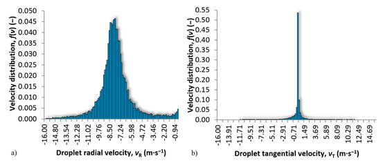
Figure 14.
Droplet radial (a) and tangential (b) velocity distribution at a position (140,0,40) mm (x,y,z).
Using the treated data, 3D surface graphs of absolute radial velocity in relation to radial X- and Y-position at different axial distances (Z) were plotted and approximated using the distance weighted least squares algorithm in the TIBCO Statistica (USA) software. The 3D graphs are shown from two different orientations, and blue marks represent individual points approximated by the plane. Figure 15a shows a decrease in velocity with increasing distance. At the Z-axis 0 and 10 mm, the velocity was measured right above the liquid sheet; therefore, the measured velocities are low. The highest velocity is at the Z-axis between 40 and 50 mm, where the main liquid stream occurs and then slightly decrease (the same in 2D is shown in supplementary Figure S7). The highest radial velocity of 8.26 m s−1 was measured at a radial and axial distance of 110 and 40 mm, respectively. At the same axial distance was also the lowest measured velocity of 7.22 m s−1, but at the position corresponding to a radial distance of 165 mm (the most distant position from the nozzle axis). This is due to the kinetic energy loss in the space with increasing distance from the nozzle orifice. However, at the 0 and 10 mm Z-distance, there is an obvious decrease of the velocity profile, which is higher than could be expected from the loss of kinetic energy. This is probably caused by the large spray angle (the liquid in the upper cone is sprayed from the nozzle almost horizontally) and a descent of the liquid sheet due to gravity. In a distance between 110 and 165 mm, the descent by 15 mm can be expected. The kinetic energy loss (liquid flow deceleration) is also due to the friction caused by the complicated nozzle orifice geometry. This can be expressed using the Euler number (Eu) (i.e., the ratio of pressure loss due to flow restriction and kinetic energy per volume of the flow):
where ν is the liquid velocity inside the nozzle. Figure 16 shows the relationship between Euler number and Reynolds number at nozzle orifice (Reo) of the flow inside the nozzle (Equation (7)).
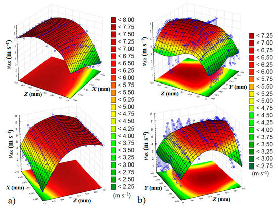
Figure 15.
Absolute radial velocity in relation to X-distance (a) and Y-distance (b).
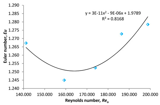
Figure 16.
Euler number in relation to Reynolds number at nozzle.
We can see an atypical behavior of the nozzle studied. The friction losses expressed in terms of Eu are quite low (ideal frictionless flow corresponds to Eu = 1). However, Eu first decreases with increasing Re from approx. 1.4 × 10⁵ to 1.6 × 10⁵. Such a high Re corresponds to fully developed turbulent flow and any further increase is expected to rather increase pressure losses due to friction. Nonetheless, the extraordinary nozzle orifice geometry probably causes this slight anomaly and up to the point corresponding to Re of about 1.6 × 10⁵ the friction losses slightly decreased. This can outline ideal operation conditions for the use of this nozzle in gas cleaning applications. At lower Re the friction is higher but the turbulence is lower at the same time causing non-ideal conditions for the removal of the contaminative gases from air. With further increase of Re, Eu starts to also increase up to 1.28 corresponding to an inlet pressure of 2 bars (i.e., a flowrate of 1.76 L/s; refer to Table 1). It is further suggested for future work to measure a wider range of inlet pressures to obtain more complex idea about the nozzle behavior. However, we were limited to a pressure of 3 bars at the highest due to the nozzle made of Teflon (for higher pressures, metal nozzles are necessary). The nozzle behavior described in Figure 16 is quite different compared to a hollow-cone pressure swirl nozzle as studied by Nonnenmacher and Piesche [96]. The authors observed higher values of Eu increasing approx. from 50 to 80 with Re increasing approx. from 300 to 50,000.
5. Conclusions
This work tried to provide basic characteristics of a spray produced using a spiral nozzle and compare the spray properties with other atomizers. The spray produced using the spiral nozzle consists of three concentric liquid cones creating a full-cone pattern. Typical spray angle is quite large compared to other nozzles, the upper large cone having a spray angle as large as 150°. At the adopted conditions, the droplet-size distribution was larger. Sauter mean diameter was 1.201 mm, the same is true for velocity which was, conversely, lower compared to, for example, effervescent atomizers. Ideal operational conditions were found to be at a liquid flowrate of 1.41 L/s corresponding to an inlet pressure of 1.25 bar. Based on the initial comparison with the theory, we can see a gap in the mathematical description of the conical sheets. Therefore, future research is necessary to further understand the breakup behavior of the liquid jets on plates horizontal as well as at different angles. Future work will also focus on the description of the conical sheet breakup using detailed observations with optical methods, and basic RANS simulations (Reynolds-averaged Navier-Stokes equations) and large eddy simulations (LES) with adaptable computational mesh to catch as many of the smallest structures and droplets formed during the sheet atomization as possible. The presented results will also serve as the experimental verification of the developed CFD models.
Supplementary Materials
The following are available online at https://www.mdpi.com/2227-9717/7/12/911/s1, Figure S1: Representation of the measured position in relation to the spray (a) and a detailed demonstration/description of the same (b); Figure S2: A snapshot of classical (a) and modified (b) photography, Figure S3: Impact pressures of individual measurements in plane 2; Table S1: The parameters of the Archimedean spiral equation; Table S2: Effective spraying angles γef of small and large cones for planes 1, 3, and 5; Table S3: Effective spraying angles γef of small and large cones for planes 1, 3, and 5; Figure S4: Comparison of the spray at two different flowrates of 1.25 l/s corresponding to a pressure at the nozzle of 1 bar (A) and 1.76 l/s corresponding the a pressure at the nozzle of 2 bars (B); Figure S5: Deformation (yellow-circled) and vibrational breakup (red-circled) of droplets; Table S4: Results of the Kolmogorov–Smirnov test; Figure S6: Detail of individual droplets (a) and evaluation of their size (b); Figure S7: Velocity profile of the liquid sheet in relation to radial distance X at individual axial positions Z.
Author Contributions
O.K. conceived, designed, and performed the experiments and evaluated data; P.B. evaluated the data and wrote the paper; T.S. conceived the work, provided the laboratory with the equipment and supervision.
Funding
This paper has been supported by the project “Computer Simulations for Effective Low-Emission Energy Engineering” funded as project no. CZ.02.1.01/0.0/0.0/16_026/0008392 by Operational Program Research, Development and Education, Priority axis 1: Strengthening capacity for high-quality research.
Conflicts of Interest
The authors declare no conflicts of interest.
References
- Seyboth, O.; Zimmermann, S.; Heidel, B.; Scheffknecht, G. Development of a Spray Scrubbing Process for Post Combustion CO2 Capture with Amine Based Solvents. Energy Procedia 2014, 63, 1667–1677. [Google Scholar] [CrossRef]
- Vlasák, J.; Svěrák, T.; Dreveny, L.; Kalivoda, J. Air Purification from CO2 Gas Using a Scrubber and Suggestions to Reach a Better Efficiency. Mater. Sci. Forum 2019, 955, 1–6. [Google Scholar] [CrossRef]
- Dumont, É. Mass Transfer in Multiphasic Gas/Liquid/Liquid Systems. KLa Determination Using the Effectiveness-Number of Transfer Unit Method. Processes 2018, 6, 156. [Google Scholar] [CrossRef]
- Li, Z.; Wang, S.; Wang, X. Spray characteristics of spiral nozzles used in wet flue gas desulfurization system. J. Southeast Univ. Nat. Sci. Ed. 2008, 38, 493–495. [Google Scholar]
- Dong, H.; Ma, H.; Li, D.; Sun, G. Comparative study on scrubbing desulfurization performances of spiral nozzle and Dynawave nozzle. Pet. Refin. Eng. 2006, 36, 32–35. [Google Scholar]
- Sadegh-Vaziri, R.; Amovic, M.; Ljunggren, R.; Engvall, K. A Medium-Scale 50 MWfuel Biomass Gasification Based Bio-SNG Plant: A Developed Gas Cleaning Process. Energies 2015, 8, 5287–5302. [Google Scholar] [CrossRef]
- Byeon, S.-H.; Lee, B.-K.; Raj Mohan, B. Removal of ammonia and particulate matter using a modified turbulent wet scrubbing system. Sep. Purif. Technol. 2012, 98, 221–229. [Google Scholar] [CrossRef]
- Zhou, J.; Zhou, S.; Zhu, Y. Characterization of Particle and Gaseous Emissions from Marine Diesel Engines with Different Fuels and Impact of After-Treatment Technology. Energies 2017, 10, 1110. [Google Scholar] [CrossRef]
- Balas, M.; Lisy, M.; Kubicek, J.; Pospisil, J. Syngas Cleaning by Wet Scrubber. WSEAS Trans. Heat Mass Transf. 2014, 9, 195–204. [Google Scholar]
- Nwokolo, N.; Mamphweli, S.; Makaka, G. Analytical and Thermal Evaluation of Carbon Particles Recovered at the Cyclone of a Downdraft Biomass Gasification System. Sustainability 2017, 9, 645. [Google Scholar] [CrossRef]
- Avveduto, A.; Ferella, F.; De Giovanni, M.; Innocenzi, V.; Pace, L.; Tripodi, P. L′Aquila Smart Clean Air City: The Italian Pilot Project for Healthy Urban Air. Environments 2017, 4, 78. [Google Scholar] [CrossRef]
- Adamec, V.; Schüllerová, B.; Hrabová, K.; Skeřil, R.; Kadlec, R.; Bulejko, P.; Adam, V. The nanoparticles concentration in the traffic loaded urban area. In Proceedings of the 9th International Conference on Nanomaterials—Research and Application, NANOCON 2017, Brno, Czech Republic, 18–20 October 2018; pp. 698–703. [Google Scholar]
- Poláčik, J.; Šnajdárek, L.; Špiláček, M.; Pospíšil, J.; Sitek, T. Particulate Matter Produced by Micro-Scale Biomass Combustion in an Oxygen-Lean Atmosphere. Energies 2018, 11, 3359. [Google Scholar] [CrossRef]
- Abdulwahid, A.A.; Situ, R.; Brown, R.J. Underground Diesel Exhaust Wet Scrubbers: Current Status and Future Prospects. Energies 2018, 11, 3006. [Google Scholar] [CrossRef]
- Sitek, T.; Pospíšil, J.; Poláčik, J.; Špiláček, M.; Varbanov, P. Fine combustion particles released during combustion of unit mass of beechwood. Renew. Energy 2019, 140, 390–396. [Google Scholar] [CrossRef]
- Svěrák, T.; Bulejko, P.; Krištof, O.; Kejík, P.; Kalivoda, J.; Horský, J. Covering ability of aluminum pigments prepared by milling processes. Powder Technol. 2017, 305, 396–404. [Google Scholar] [CrossRef]
- Sverak, T. Sorption purpose lime hydrate grinding. Int. J. Miner. Process. 2004, 74, S379–S383. [Google Scholar] [CrossRef]
- Bulejko, P.; Adamec, V.; Skeřil, R.; Schüllerová, B.; Bencko, V. Levels and Health Risk Assessment of PM10 Aerosol in Brno, Czech Republic. Cent. Eur. J. Public Health 2017, 25, 129–134. [Google Scholar] [CrossRef][Green Version]
- Bulejko, P.; Svěrák, T.; Dohnal, M.; Pospíšil, J. Aerosol filtration using hollow-fiber membranes: Effect of permeate velocity and dust amount on separation of submicron TiO2 particles. Powder Technol. 2018, 340, 344–353. [Google Scholar] [CrossRef]
- Sverak, T.; Bulejko, P.; Ostrezi, J.; Kristof, O.; Kalivoda, J.; Kejik, P.; Mayerova, K.; Adamcik, M. Separation of gaseous air pollutants using membrane contactors. IOP Conf. Ser. Earth Environ. Sci. 2017, 92, 012061. [Google Scholar] [CrossRef]
- Bulejko, P. Numerical Comparison of Prediction Models for Aerosol Filtration Efficiency Applied on a Hollow-Fiber Membrane Pore Structure. Nanomaterials 2018, 8, 447. [Google Scholar] [CrossRef]
- Ghasem, N. Modeling and Simulation of the Absorption of CO2 and NO2 from a Gas Mixture in a Membrane Contactor. Processes 2019, 7, 441. [Google Scholar] [CrossRef]
- Bulejko, P.; Krištof, O.; Dohnal, M.; Svěrák, T. Fine/ultrafine particle air filtration and aerosol loading of hollow-fiber membranes: A comparison of mathematical models for the most penetrating particle size and dimensionless permeability with experimental data. J. Membr. Sci. 2019, 592, 117393. [Google Scholar] [CrossRef]
- Bogacki, J.; Marcinowski, P.; Majewski, M.; Zawadzki, J.; Sivakumar, S. Alternative Approach to Current EU BAT Recommendation for Coal-Fired Power Plant Flue Gas Desulfurization Wastewater Treatment. Processes 2018, 6, 229. [Google Scholar] [CrossRef]
- Gao, G.; Wang, C.; Kou, Z. Experimental Studies on the Spraying Pattern of a Swirl Nozzle for Coal Dust Control. Appl. Sci. 2018, 8, 1770. [Google Scholar] [CrossRef]
- Chabičovský, M.; Hnízdil, M.; Tseng, A.A.; Raudenský, M. Effects of oxide layer on Leidenfrost temperature during spray cooling of steel at high temperatures. Int. J. Heat Mass Transf. 2015, 88, 236–246. [Google Scholar] [CrossRef]
- Brozova, T.; Chabicovsky, M.; Horsky, J. Influence of the Surface Roughness on the Cooling Intensity During Spray Cooling. In Proceedings of the 25th Anniversary International Conference on Metallurgy and Materials (METAL), Ostrava, Czech Republic, 25–27 May 2016; Volume 2016, pp. 41–46. [Google Scholar]
- Tseng, A.A.; Raudensky, M.; Lee, T.-W. Liquid Sprays for Heat Transfer Enhancements: A Review. Heat Transf. Eng. 2016, 37, 1401–1417. [Google Scholar] [CrossRef]
- Stransky, M.; Brozova, T.; Raudensky, M.; Hnizdil, M.; Turon, R. Effect of Various Spray Cooling Configurations on Hardness Profile of Tubes. In Proceedings of the 24th International Conference on Metallurgy and Materials, Ostrava, Czech Republic, 3–5 June 2015; Volume 2015, pp. 880–885. [Google Scholar]
- Lee, T.-W.; Hnizdil, M.; Chabicovsky, M.; Raudensky, M. Approximate Solution to the Spray Heat Transfer Problem at High Surface Temperatures and Liquid Mass Fluxes. Heat Transf. Eng. 2018, 40, 1649–1655. [Google Scholar] [CrossRef]
- Votavová, H.; Pohanka, M.; Bulejko, P. Cooling homogeneity measurement during hydraulic descaling in spray overlapping area. In Proceedings of the 24th International Conference on Metallurgy and Materials, Brno, Czech Republic, 3–5 June 2015; pp. 265–270. [Google Scholar]
- Zhang, D.; Li, Z.; Yi, W.; Wang, F. Test study of spray characteristics of spiral nozzle in the spray tower. Acta Energiae Solaris Sin. 2013, 34, 1969–1972. [Google Scholar]
- Ren, Z.; Hao, Y.; Wang, B. Experimental Analysis on Spiral Pressure Nozzle and Spray Angle Control in the Spray Dryer. In Proceedings of the 2011 International Conference on Internet Computing and Information Services, Hong Kong, China, 17–18 September 2011; pp. 163–165. [Google Scholar]
- Cong, H.; Li, X.; Li, Z.; Li, H.; Gao, X. Combination of spiral nozzle and column tray leading to a new direction on the distillation equipment innovation. Sep. Purif. Technol. 2016, 158, 293–301. [Google Scholar] [CrossRef]
- Cheng, X.M.; Hashimoto, B.; Kage, S.; Matsumae, Y.; Horii, K.; Ohsumi, K. Flow in Spiral Nozzle for Rope-installation in Petrochemical Pipeline Repairs. J. Jpn. Pet. Inst. 1992, 35, 382–389. [Google Scholar] [CrossRef]
- Tanner, G.; Knasiak, K.F. Spray Characterization of Typical Fire Suppression Nozzles. In Proceedings of the Third International Water Mist Conference, Madrid, Spain, 22–24 September 2003; pp. 1–16. [Google Scholar]
- Jiang, L.; Wu, R.; Zhao, H.; Mei, P.; Zhang, Q.; Zhu, J.; Xiao, J.; Lei, B. Middle or low water pressure direct spiral double helix converging nozzle structure optimization and flow field analysis. High Technol. Lett. 2015, 21, 261–268. [Google Scholar]
- Wąsik, W.; Walczak, A.; Węsierski, T. The impact of fog nozzle type on the distribution of mass spray density. MATEC Web Conf. 2018, 247, 00058. [Google Scholar] [CrossRef]
- Liu, N.-L.; Zhang, X. Distribution of droplet diameters and the spline of their empirical equation for spiral nozzle. J. Exp. Fluid Mech. 2006, 20, 8–12. [Google Scholar]
- Liu, N.; Zhang, X. Experimental research on spray and flow rate characteristics of spiral nozzle. Trans. Chin. Soc. Agric. Mach. 2006, 37, 79–82. [Google Scholar]
- Zhou, H.; Guo, W.; Zhu, Y.; Ma, W. Flow Distribution Characteristics of Low-pressure High-flux Spiral Nozzles. J. Chin. Soc. Power Eng. 2017, 37, 577–583. [Google Scholar]
- Li, C.; Wang, S.; Zhong, Z.; Zhang, X.; Kang, L. Research on spray surfaces geometry model of spiral nozzles with involute atomization. Trans. Chin. Soc. Agric. Mach. 2007, 38, 19. [Google Scholar]
- Kalata, W.; Brown, K.J.; Schick, R.J. Air Assisted Atomization in Spiral Type Nozzles. In Proceedings of the 25th Annual Conference on Liquid Atomization and Spray Systems, ILASS Americas, Pittsburgh, PA, USA, 21–23 May 2013; p. 8. [Google Scholar]
- Bete TF Spray Nozzle. Available online: https://www.johnbrooks.ca/product/bete-tf-spray-nozzle/ (accessed on 14 May 2019).
- Han, H.; Wang, P.; Liu, R.; Li, Y.; Wang, J.; Jiang, Y. Experimental study on atomization characteristics of two common spiral channel pressure nozzles. E3S Web Conf. 2019, 81, 01022. [Google Scholar] [CrossRef]
- Kim, T.H.; Matsuo, S.; Setoguchi, T.; Yu, S. A study on flow characteristics in a spiral flow nozzle. Int. J. Turbo Jet Engines 2006, 23, 129–136. [Google Scholar] [CrossRef]
- Matsuo, S.; Kim, T.-H.; Setoguchi, T.; Kim, H.D.; Lee, Y.-W. Effect of nozzle geometry on the flow characteristics of spiral flow generated through an annular slit. J. Therm. Sci. 2007, 16, 149–154. [Google Scholar] [CrossRef]
- Jain, M.; John, B.; Iyer, K.N.; Prabhu, S.V. Characterization of the full cone pressure swirl spray nozzles for the nuclear reactor containment spray system. Nucl. Eng. Des. 2014, 273, 131–142. [Google Scholar] [CrossRef]
- Zacarías, A.; Venegas, M.; Lecuona, A.; Ventas, R.; Carvajal, I. Experimental assessment of vapour adiabatic absorption into solution droplets using a full cone nozzle. Exp. Therm. Fluid Sci. 2015, 68, 228–238. [Google Scholar] [CrossRef]
- Valencia-Bejarano, M.; Langrish, T.A.G. Experimental investigation of droplet coalescence in a full-cone spray from a two-fluid nozzle using laser diffraction measurements. At. Sprays 2004, 14, 355–374. [Google Scholar] [CrossRef]
- Tseng, A.A.; Bellerová, H.; Pohanka, M.; Raudensky, M. Effects of titania nanoparticles on heat transfer performance of spray cooling with full cone nozzle. Appl. Therm. Eng. 2014, 62, 20–27. [Google Scholar] [CrossRef]
- Sada, E.; Takahashi, K.; Morikawa, K.; Ito, S. Drop size distribution for spray by full cone nozzle. Can. J. Chem. Eng. 1978, 56, 455–459. [Google Scholar] [CrossRef]
- Naz, M.Y.; Sulaiman, S.A.; Ariwahjoedi, B.; Zilati, K. Visual characterization of heated water spray jet breakup induced by full cone spray nozzles. J. Appl. Mech. Tech. Phys. 2015, 56, 211–219. [Google Scholar] [CrossRef]
- Naz, M.Y.; Sulaiman, S.A.; Ariwahjoedi, B.; Ku Shaari, K.Z. Investigation of vortex clouds and droplet sizes in heated water spray patterns generated by axisymmetric full cone nozzles. Sci. World J. 2013, 2013. [Google Scholar] [CrossRef]
- Kohnen, B.T.; Pieloth, D.; Musemic, E.; Walzel, P. Characterization of full cone nozzles. At. Sprays 2011, 21, 317–325. [Google Scholar] [CrossRef]
- Jiang, P.; Wang, Q.; Sabariman, I.; Specht, E. Experimental study on heat transfer of pressurized spray cooling on the heated plate by using 45° full cone nozzles. Appl. Mech. Mater. 2014, 535, 32–36. [Google Scholar] [CrossRef]
- Bellerová, H.; Tseng, A.A.; Pohanka, M.; Raudensky, M. Heat transfer of spray cooling using alumina/water nanofluids with full cone nozzles. Heat Mass Transf. 2012, 48, 1971–1983. [Google Scholar] [CrossRef]
- Jašíková, D.; Kotek, M.; Lenc, T.; Kopecký, V. The study of full cone spray using interferometric particle imaging method. EPJ Web Conf. 2012, 25, 01033. [Google Scholar] [CrossRef]
- Standard Full Cone Spiral Nozzle—BETE Online Catalogue. Available online: http://www.spray-nozzle.co.uk/docs/default-source/spec-sheet-pdf′s/tf-full-cone-data-sheet.pdf?sfvrsn=5cb16e8d_5 (accessed on 1 May 2019).
- Lefebvre, A.H.; McDonell, V.G. Atomization and Sprays; CRC Press: Boca Raton, FL, USA, 2017; ISBN 978-1-315-12091-1. [Google Scholar]
- Rahman, M.A.; Heidrick, T.; Fleck, B.A. Correlations between the two-phase gas/liquid spray atomization and the Stokes/aerodynamic Weber numbers. J. Phys. Conf. Ser. 2009, 147, 012057. [Google Scholar] [CrossRef]
- Guildenbecher, D.R.; López-Rivera, C.; Sojka, P.E. Droplet Deformation and Breakup. In Handbook of Atomization and Sprays: Theory and Applications; Ashgriz, N., Ed.; Springer: Boston, MA, USA, 2011; pp. 145–156. ISBN 978-1-4419-7264-4. [Google Scholar]
- Ashgriz, N.; Li, X.; Sarchami, A. Instability of Liquid Sheets. In Handbook of Atomization and Sprays: Theory and Applications; Ashgriz, N., Ed.; Springer: Boston, MA, USA, 2011; pp. 75–95. ISBN 978-1-4419-7264-4. [Google Scholar]
- Vegad, C.S.; Chakravarthy, S.R.; Kumar, A. Dynamics of a radially expanding circular liquid sheet and its atomization characteristics. Fire Saf. J. 2018, 100, 51–63. [Google Scholar] [CrossRef]
- Taylor, G.I. The dynamics of thin sheets of fluid. III. Disintegration of fluid sheets. Proc. R. Soc. Lond. Ser. Math. Phys. Sci. 1959, 253, 313–321. [Google Scholar]
- Pilch, M.; Erdman, C.A. Use of breakup time data and velocity history data to predict the maximum size of stable fragments for acceleration-induced breakup of a liquid drop. Int. J. Multiph. Flow 1987, 13, 741–757. [Google Scholar] [CrossRef]
- Faeth, G.M.; Hsiang, L.-P.; Wu, P.-K. Structure and breakup properties of sprays. Int. J. Multiph. Flow 1995, 21, 99–127. [Google Scholar] [CrossRef]
- Guildenbecher, D.R.; López-Rivera, C.; Sojka, P.E. Secondary atomization. Exp. Fluids 2009, 46, 371. [Google Scholar] [CrossRef]
- Luo, K.; Shao, C.; Chai, M.; Fan, J. Level set method for atomization and evaporation simulations. Prog. Energy Combust. Sci. 2019, 73, 65–94. [Google Scholar] [CrossRef]
- Zhao, H.; Liu, H. Breakup Morphology and Mechanisms of Liquid Atomization. Adv. Jet Engines 2019. [Google Scholar]
- Chryssakis, C.A.; Assanis, D.N.; Tanner, F.X. Atomization Models. In Handbook of Atomization and Sprays: Theory and Applications; Ashgriz, N., Ed.; Springer US: Boston, MA, USA, 2011; pp. 215–231. ISBN 978-1-4419-7264-4. [Google Scholar]
- Gelfand, B.E. Droplet breakup phenomena in flows with velocity lag. Prog. Energy Combust. Sci. 1996, 22, 201–265. [Google Scholar] [CrossRef]
- Watson, E.J. The radial spread of a liquid jet over a horizontal plane. J. Fluid Mech. 1964, 20, 481–499. [Google Scholar] [CrossRef]
- Ren, N.; Blum, A.; Zheng, Y.; Do, C.; Marshall, A. Quantifying the Initial Spray from Fire Sprinklers. Fire Saf. Sci. 2008, 9, 503–514. [Google Scholar] [CrossRef]
- Zhou, X.; Yu, H.-Z. Experimental investigation of spray formation as affected by sprinkler geometry. Fire Saf. J. 2011, 46, 140–150. [Google Scholar] [CrossRef]
- Dombrowski, N.; Johns, W.R. The aerodynamic instability and disintegration of viscous liquid sheets. Chem. Eng. Sci. 1963, 18, 203–214. [Google Scholar] [CrossRef]
- Weber, C. The break-up of liquid jets (Zum Zerfall eines Flüssigkeitsstrahles). ZAMM J. Appl. Math. Mech. Z. Angew. Math. Mech. 1931, 11, 136–154. [Google Scholar] [CrossRef]
- Dombrowski, N.; Hooper, P.C. The effect of ambient density on drop formation in sprays. Chem. Eng. Sci. 1962, 17, 291–305. [Google Scholar] [CrossRef]
- Wu, D.; Guillemin, D.; Marshall, A.W. A modeling basis for predicting the initial sprinkler spray. Fire Saf. J. 2007, 42, 283–294. [Google Scholar] [CrossRef]
- Crowe, C.T.; Schwarzkopf, J.D.; Sommerfeld, M.; Tsuji, Y. Multiphase Flows with Droplets and Particles, 2nd ed.; CRC Press: Boca Raton, FL, USA, 2011; ISBN 978-1-4398-4050-4. [Google Scholar]
- Xia, Y.; Khezzar, L.; Alshehhi, M.; Hardalupas, Y. Droplet size and velocity characteristics of water-air impinging jet atomizer. Int. J. Multiph. Flow 2017, 94, 31–43. [Google Scholar] [CrossRef]
- Liu, C.; Liu, F.; Yang, J.; Mu, Y.; Hu, C.; Xu, G. Experimental investigations of spray generated by a pressure swirl atomizer. J. Energy Inst. 2019, 92, 210–221. [Google Scholar] [CrossRef]
- Huang, J.C.P. The break-up of axisymmetric liquid sheets. J. Fluid Mech. 1970, 43, 305–319. [Google Scholar] [CrossRef]
- Jordan, S.J.; Ryder, N.L.; Repcik, J.; Marshall, A.W. Spatially-resolved spray measurements and their implications. Fire Saf. J. 2017, 91, 723–729. [Google Scholar] [CrossRef]
- Myers, T.; Trouvé, A.; Marshall, A. Predicting sprinkler spray dispersion in FireFOAM. Fire Saf. J. 2018, 100, 93–102. [Google Scholar] [CrossRef]
- Dai, Z.; Faeth, G.M. Temporal properties of secondary drop breakup in the multimode breakup regime. Int. J. Multiph. Flow 2001, 27, 217–236. [Google Scholar] [CrossRef]
- Krzeczkowski, S.A. Measurement of liquid droplet disintegration mechanisms. Int. J. Multiph. Flow 1980, 6, 227–239. [Google Scholar] [CrossRef]
- Cao, X.-K.; Sun, Z.-G.; Li, W.-F.; Liu, H.-F.; Yu, Z.-H. A new breakup regime of liquid drops identified in a continuous and uniform air jet flow. Phys. Fluids 2007, 19, 057103. [Google Scholar] [CrossRef]
- Sirignano, W.A.; Mehring, C. Review of theory of distortion and disintegration of liquid streams. Prog. Energy Combust. Sci. 2000, 26, 609–655. [Google Scholar] [CrossRef]
- Sun, Y.; Alkhedhair, A.M.; Guan, Z.; Hooman, K. Numerical and experimental study on the spray characteristics of full-cone pressure swirl atomizers. Energy 2018, 160, 678–692. [Google Scholar] [CrossRef]
- Wittner, M.O.; Karbstein, H.P.; Gaukel, V. Air-Core-Liquid-Ring (ACLR) Atomization: Influences of Gas Pressure and Atomizer Scale Up on Atomization Efficiency. Processes 2019, 7, 139. [Google Scholar] [CrossRef]
- Li, W.; Qian, L.; Song, S.; Zhong, X. Numerical Study on the Influence of Shaping Air Holes on Atomization Performance in Pneumatic Atomizers. Coatings 2019, 9, 410. [Google Scholar] [CrossRef]
- Darwish Ahmad, A.; Abubaker, A.M.; Salaimeh, A.A.; Akafuah, N.K. Schlieren Visualization of Shaping Air during Operation of an Electrostatic Rotary Bell Sprayer: Impact of Shaping Air on Droplet Atomization and Transport. Coatings 2018, 8, 279. [Google Scholar] [CrossRef]
- Ren, N.; Baum, H.R.; Marshall, A.W. A comprehensive methodology for characterizing sprinkler sprays. Proc. Combust. Inst. 2011, 33, 2547–2554. [Google Scholar] [CrossRef]
- Elkotb, M.M. Fuel atomization for spray modelling. Prog. Energy Combust. Sci. 1982, 8, 61–91. [Google Scholar] [CrossRef]
- Nonnenmacher, S.; Piesche, M. Design of hollow cone pressure swirl nozzles to atomize Newtonian fluids. Chem. Eng. Sci. 2000, 55, 4339–4348. [Google Scholar] [CrossRef]
© 2019 by the authors. Licensee MDPI, Basel, Switzerland. This article is an open access article distributed under the terms and conditions of the Creative Commons Attribution (CC BY) license (http://creativecommons.org/licenses/by/4.0/).