Article

Reliability Evaluation Method Considering Demand Response (DR) of Household Electrical Equipment in Distribution Networks

1
State Grid Suzhou Power Supply Company, Suzhou 215004, China
2
School of Electrical and Automation Engineering, Hefei University of Technology, Hefei 230009, China
3
State Grid Suzhou Power Supply Company Suzhou Electric Power Design Institute Co., Ltd., Suzhou 215004, China
*
Author to whom correspondence should be addressed.
Processes 2019, 7(11), 799; https://doi.org/10.3390/pr7110799
Submission received: 30 September 2019 / Accepted: 23 October 2019 / Published: 3 November 2019

Abstract

:
The load characteristic of typical household electrical equipment is elaborately analyzed. Considering the electric vehicles’ (EVs’) charging behavior and air conditioning’s thermodynamic property, an electricity price-based demand response (DR) model and an incentive-based DR model for two kinds of typical high-power electrical equipment are proposed to obtain the load curve considering two different kinds of DR mechanisms. Afterwards, a load shedding strategy is introduced to improve the traditional reliability evaluation method for distribution networks, with the capacity constraints of tie lines taken into account. Subsequently, a reliability calculation method of distribution networks considering the shortage of power supply capacity and outages is presented. Finally, the Monte Carlo method is employed to calculate the reliability index of distribution networks with different load levels, and the impacts of different DR strategies on the reliability of distribution networks are analyzed. The results show that both DR strategies can improve the distribution system reliability.

1. Introduction

China’s electricity generation and demands have been growing rapidly in recent years, but the annual utilization hours of power generation equipment are decreasing year-by-year, and the peak-valley difference of power system loads is gradually expanding. Statistically, China’s total electricity consumption in 2018 was 6840 billion kW h, up 8.5% year-on-year, which is the highest growth rate since 2012. The maximum cooling loads in summer have reached 260 million kW, with a year-on-year growth of 10.5%, accounting for 27.8% of the maximum loads. However, the average utilization hours of power generation equipment in power plants of 6000 kW or above in China in 2019 were only 3862 h. In general, increasing generation capacity to meet peak load electricity demands will lead to an increase in investment cost and a decrease in equipment utilization hours, which cannot meet the requirements of economic operation of power grid and optimal allocation of resources.
As a prospective solution to the above issues, demand response (DR) has been widely proposed in many researches [1,2], where DR is regarded as an important measure to facilitate the penetration of renewable energy [3], realize friendly source-load interaction, balance the fluctuations of load profile, and consequently improve the system reliability and operation economy [4,5]. With the rapid development and application practice of ubiquitous power Internet of Things (IOT) technology, bi-directional communication and intelligent control between power grid and user side can be supported [6]. DR, normally including electricity price-based DR and incentive-based DR [7,8], could regulate consumers’ electricity behaviors to reduce peak loads and improve load curve [9,10,11,12]. Real-time electricity price can reflect the relationship between power supply and demand, and thus a reasonable electricity price mechanism could efficiently guide users to participate in peak shaving and valley filling [13,14]. For incentive-based DR, users can be encouraged to adjust load demands by signing an agreement on condition of certain economic compensation [15,16].
Residential loads can be regarded as a resource that can be flexibly dispatched in the distribution network, which can be divided into temperature-controlled equipment, non-temperature-controlled equipment, and uncontrollable equipment according to the operation characteristics of household power loads [17]. Temperature-controlled equipment, such as air conditioning, can participate in DR by adjusting comfort interval [18]. Non-temperature-controlled equipment, such as electric vehicles (EVs), can change electricity consumption behavior by responding to real-time electricity price [19]. In [20], an optimal scheduling model, which considers the reliability of microgrid and the customers’ electricity cost, is established to regulate the electricity consumption of home appliances and EVs. In [21], a home energy management system is proposed and an energy consumption optimization model is presented to minimize the electricity cost, and dynamic programming is employed to solve the real-time rescheduling model for determining the on/off status of home appliances. In [22], a customer utility function is defined and a novel economic model is presented to determine the customers’ reaction to electricity price change. Reference [23] points out that the implementation of DR is limited by the accurate forecast of demand and price elasticity, and therefore presents a novel DR model based on consumers’ information while avoiding predicting these two items. Both air conditioning loads and EV loads account for a large proportion in the daily load, and therefore enjoy a large potential for DR.
The reliability of distribution systems changes nonlinearly with the increase or decrease of the loads. By far, this issue has been studied by many researchers. A time-of-use electricity price-based DR model is established in [24,25] to identify the influence of electricity price-based DR on distribution network reliability. In [26], the incentive-based DR mechanism is systematically investigated to design the DR contract based on load transfer and load reduction, respectively, and then a bidding decision optimization model is presented to maximize the benefits of load aggregators. The influence of incentive-based DR on distribution network reliability is analyzed. However, the aforementioned works evaluate the reliability of distribution networks under a single DR mechanism. Actually, it is necessary to consider the comprehensive effects of two kinds of DR mechanism. In order to evaluate the performance of the implementation of DR, the customer baseline load is introduced in [27] with two different calculating methods, the day matching method and regression analysis. In [28], the concept of a virtual power plant is introduced, and the cost models considering the incentive- and electricity-based DR are respectively proposed to quantitatively analyze the influence of the uncertainty of DR on the expected losses of energy in distribution networks. It should be mentioned that the tie line capacity is generally assumed to be infinity when distribution network reliability is analyzed, which means the loads in non-fault areas could be entirely transferred after fault isolation, leading to overoptimistic reliability results. The line capacity constraint is considered in [29] when the outage is caused by a failure, assuming the power supply is sufficient. Nevertheless, the quantity of power users is rapidly increasing and the network structure is gradually becoming complex. The equipment in distribution networks that has not been upgraded, in time, may lead to electricity supply shortage in distribution systems. Therefore, these models may not perform well for calculation accuracy.
In this paper, two typical items of household equipment, EV and air conditioning, are taken into account. The DR models are presented based on different DR mechanisms, while considering load characteristic, charging behavior, and thermodynamic property. Also, it is necessary to present an improved distribution network reliability evaluation method considering tie line capacity constraint and power supply capacity shortage constraint, and therefore the accuracy of distribution network reliability index can be improved. Given the aforementioned reviewed literature, the contributions can be summarized as:
  • The load characteristic of two typical items of household electrical equipment is elaborately analyzed.
  • An electricity price-based DR model and an incentive-based DR model are proposed for two typical items of high-power electrical equipment, considering charging behavior and thermodynamic property.
  • A load shedding strategy is introduced to improve the traditional reliability evaluation method for distribution networks, while taking into account the capacity constraints.
  • A reliability calculation method of distribution networks with shortage of power supply capacity and faults taken into consideration is presented.
The remainder of this paper is given as follows. Section 2 present an electricity price-based DR model and an incentive-based DR model for two kinds of typical high-power electrical equipment. A load shedding strategy is proposed in Section 3, and the reliability index is detailed in Section 4. Section 5 proposes an improved reliability evaluation method of distribution networks, with shortage of power supply capacity and faults taken into account. The numerical results of the developed model are discussed in Section 6. The final section of the paper outlines conclusions based on this study.

2. DR Modeling

DR can be categorized into two types: Electricity price-based DR and incentive-based DR. The former guides users’ electricity behavior by varying electricity price, while the latter adjusts electricity loads by contracts and compensation terms signed by customers. In this paper, two kinds of household electrical equipment, i.e., EVs and air conditioners, are chosen to establish DR models.

2.1. DR Modeling of EVs Based on Electricity Price

The charging loads of EVs depend on the user’s habits, driving distance, status of the battery charge, the time when EVs plug in and out of distribution systems. Generally, EV owners use their cars during the day and charge them at night for the next day’s trip. Real-time electricity price can reflect the relationship between power supply and demand, and therefore, real-time electricity price could be employed to guide users to adjust charging behavior of EVs. Given the development of communication technology, intelligent switch technology, and Internet of Things industry, the DR strategy for EV proposed in this paper can be realized in the near future.

2.1.1. Optimization Objective

When EVs plug into the grid, the owners are required to set the time of departure and the expected state of charge (SOC). The DR strategy is presented to minimize the charging cost of the owners by optimizing the charging power of EVs at each time interval according to the real-time electricity price. It should be mentioned that the owners are willing to participate in the DR because the cost of EV charging can be reduced while the owners’ demands for the next day’s travel are met. For a single EV, the objective function is defined as follows:
M i n t = 1 T P t EV C t Δ t
The objective Function (1) is devoted to minimize the charging cost of a single EV. P t E V and Ct represent the charging power of EV and time-of-use electricity price at time t, Δt is the length of one time interval, and T is the number of time intervals within the scheduling time.

2.1.2. Constraints

(1) SOC constraint
Considering the charging efficiency of the battery in an EV, the recursive formula of the SOC can be described as:
S o c t + 1 = S o c t + ε c h P t EV Δ t E B
S o c min S o c t S o c max
where S o c t + 1 and S o c t denote the SOC of the battery at time t + 1 and t, respectively; εch represents the charging efficiency of the battery; EB is the energy capacity of battery, and the unit is kW·h; Socmax and Socmin represent the upper and lower limit of SOC, respectively.
(2) Travel demand constraint
The SOC of the battery in an EV when it plugs out of the grid should be restricted to meet the owner’s demand for travel.
S o c t d S o c exp
where Soctd and Socexp respectively represent the actual and expected SOC of the battery at td; td denotes the time when EV plugs out, which is with strong uncertainty and can be approximately estimated according to the historical data of EVs.
(3) Battery safety constraint
SOC of the battery and the charging power in the charging process are described as:
0 P t EV P max EV
where PmaxEV represents the maximum of charging power of EV.
(4) Undispatched time constraint
P t EV = 0 t [ t s , t d ]
where ts represents the time when an EV plugs into the grid.

2.2. DR Modeling of Air Conditioners Based on Incentive

Air conditioning is chosen as the temperature-controlled load to participate in DR due to the widespread utilization of air conditioning and the large proportion of air conditioning loads in summer peak loads. Air conditioning could satisfy users’ demands for temperature through cooling or heating equipment. The acceptable temperature range for a human body is relatively wide. Therefore, air conditioning can be regarded as a DR resource with great potential and flexibility.

2.2.1. Optimization Objective

The air conditioning load could be adjusted within the time period declared by consumers to smooth the load curve and realize peak load shifting. The air conditioning loads are controlled by adjusting the setting of the temperature. The scheduling model of air conditioning loads can be formulated as follows.
min 1 T 1 t = 1 T ( P t D j = 1 N Δ P k , t a i r x k , t P ¯ D ) 2
P ¯ D = 1 T t = 1 T ( P t D j = 1 N Δ P k , t a i r x k , t )
The objective Function (7) aims to minimize the load variance, where P t D represents the base load of time t; Δ P k , t a i r denotes the load reduction of the kth air conditioner in time t; P ¯ D is the mean value of the total load in the dispatching period; N represents the total number of air conditioners; T is the number of time intervals within the scheduling time; xk,t is the binary decision variable indicating whether the kth air conditioner participates in load reduction at time t; xk,t is equal to 1 if the air conditioner k participates in scheduling at time t, and 0 otherwise.

2.2.2. Constraints

(1) Electrical constraints of air conditioners
The energy efficiency ratio of air conditioners can be defined as the ratio of power and capacity of refrigerating. It should be noted that the energy efficiency ratio of inverter air conditioning cannot be simply modeled as a constant. The mathematical relationship among power, refrigerating capacity, and frequency in actual operation can be formulated as follows:
P A = a f A + b
Q A = m f A 2 + n f A + q
Equation (9) describes the relationship between the power and frequency of air conditioners, where PA and fA represent the operating power and frequency of air conditioners, respectively. a and b are constants. Equation (10) denotes the relationship between refrigerating capacity and frequency of air conditioners, where QA represents the refrigerating capacity of air conditioners. m, n, and q are coefficients.
(2) Thermodynamic model of air conditioners
The indoor temperature is generally chosen as the control variable, which is affected by many factors, such as the indoor and outdoor heat exchange, outdoor temperature, the heat transfer between the air conditioner and the indoor air, the air heat capacity, and the air conditioning refrigerating capacity. It should be mentioned that there are many other affecting factors; therefore, precisely modeling air conditioning thermodynamic characteristics can be quite complex. The thermodynamic model of air conditioning can be approximately described as follows:
θ i n , t + 1 = θ o u t , t + 1 Q t R ( 1 e t / R C ) ( θ o u t , t θ i n , t ) e t / R C
where θin,t+1 and θin,t represent the indoor temperature at time t + 1 and t, respectively; θout,t+1 denotes the outdoor temperature at time t + 1; Qt is the air conditioning refrigerating capacity at time t; R and C are the equivalent heat resistance and heat capacity of air conditioning, with the units of °C/kW kW h/°C, respectively.
(3) Inverter air conditioning operating frequency constraint
The frequency of the inverter air conditioning can be adjusted by the compressor, and the operating frequency should meet the following constraint:
f min , k f k f max , k
where fk represents the operating frequency of the kth air conditioner; fmax,k and fmin,k denote the maximum and minimum operating frequency of the kth air conditioner, respectively.
(4) Maximum dispatchable time constraints
The maximum dispatchable number of air conditioners in the scheduling period should be restricted in order to meet the users’ comfort requirements.
t = 1 T x k , t t c , k
where tc,k is the maximum dispatchable number of the kth air conditioner.

2.2.3. Control Method

The control methods of inverter air conditioning [30] can be divided into temperature control and frequency control. The changing curve of indoor temperature and frequency under the two control methods is shown in Figure 1. In the temperature control mode, it can be found that the frequency rapidly decreases to the lowest value if the set temperature of the inverter air conditioner raises. As the room temperature gradually increases, the frequency rises with fluctuations and tends to be stable. For the frequency control mode, the frequency is also rapidly reduced to the lowest value when the set temperature raises. The frequency continues to run at the lowest value until the temperature rises to the set temperature, and meanwhile, the frequency rises to a stable value. It can be found from Figure 1 that the temperature control method is simple but it is difficult to obtain an analytical solution of frequency deviation and control period, and therefore, the frequency control method is employed to control air conditioning loads; namely, when the user sets the comfort temperature range, i.e., from θ1 to θ2, the air conditioning would operate with the lowest frequency at the first time, and then the air conditioning frequency would be adjusted to stable value for θ2.
It is assumed that the indoor temperature at time t + 1 is equal to the indoor temperature at time t in stable operation. When the air conditioning runs stably, its operation power can be calculated by Equations (9)–(11).
P t a i r = n + n 2 4 m [ q ( θ o u t , t θ 1 ) / R ] 2 m a + b
Therefore, load reduction of air conditioning can be described as:
Δ P k , t a i r = P k , t a i r a f min , k b
where P k , t a i r denotes the power demand of the kth air conditioner in stable operation at time t.

3. Reliability Evaluation of Distribution Networks Considering DR

3.1. Model of Load Transfer Capacity

When a failure occurs, non-fault areas can be supplied through tie lines after fault areas are isolated. Considering the maximum transmission capacity limit of the tie line, the transfer capacity of the tie line l can be calculated as follows [31]:
P l z = P l max P l ( 1 + β l ) 1 + β l
where Plz represents the power supplied by the tie line; Pl is the load of a line itself; Plmax is the maximum transmission power of the line l; βl is the line loss ratio of the line l.
If the tie line has already supplied heavy loads, the transfer power will not be enough to meet the power supply of all the loads in the downstream area of the fault. In this situation, the load shedding strategy described in Section 3.2 should be applied in order to meet the power supply requirements of important loads in the downstream area of the fault.

3.2. Load Shedding Strategy

The over-load operation of the feeder may occur during in the peak load period if the maximum transmission capacity limit of the feeder in the distribution network is taken into consideration. It is necessary to reduce the load amount of the feeder by cutting parts of the loads to ensure the secure and stable operation of the distribution networks. Therefore, the load shedding model is proposed and shown in Equations (17) and (18):
max i S ω i P i ( t )
s . t . { ( 1 + β ) i S P i ( t ) P S max U i , min U i U i , max
The objective Function (17) should be maximized so as to supply as much load as possible, while taking the weight of the load points into consideration. ωi is the importance coefficient of load point i for reliability requirement; S represents the collection set of all load points on the feeder; Pi(t) is the power demand of load point i at time t. Equation (18) describes the power supply capacity constraint and node voltage constraint, where PSmax represents the upper limit of the power transmitted by the feeder and Ui, Ui,max, and Ui,min are the voltage of node i and its maximum and minimum values, respectively.

4. Analysis of the Influence of DR on Distribution Network Reliability

The key of reliability evaluation is the selection and calculation of reliability index. In order to systematically study the influence of load changes caused by DR on the reliability of the distribution network, the reliability index influenced by load changes need to be firstly analyzed.

4.1. Load Point Reliability Index

(1) Load point average failure frequency index
The load point average failure frequency index is defined as the number of outages at load points in the statistical period. Long time overload operation of transformers will accelerate its aging, and then affect the average failure rate of the load point. DR can improve the load curve and reduce peak loads, thus reducing the failure frequency of load points.
(2) Load point average interruption frequency index
When the distribution transformer fails or the power supply is insufficient, load interruption occurs. The average interruption frequency index of load point i can be defined as:
P o u t a g e , i = 1 1 T t = 1 T X ( i , t )
where Poutage,i denotes the outage probability of load point i; X(I, t) is a binary decision variable for operation state of load point i at time t, which is equal to 1 in normally operating state, and 0 otherwise.

4.2. System Reliability Index

Three system reliability indexes are introduced in this paper as follows:
(1) Frequency index
Frequency index mainly refers to system average interruption frequency index (SAIFI).
(2) Time index
Time indexes mainly include customer average interruption duration index (CAIDI) and system average interruption duration index (SAIDI).
(3) Energy index
Energy not supplied (ENS) index mainly depends on the annual power outage time and load power of the system.

5. Improved Reliability Evaluation Method Based on Load Clustering

5.1. Improved Reliability Evaluation Method

According to the location of faults and their influence on other loads, the loads can be categorized into four types: (1) Type A: The loads in the fault area and their outage time depend on the time of fault isolation and repair; (2) Type B: The loads in the downstream of the fault area and their outage time depend on the load transfer time; (3) Type C: The loads in the upstream of the fault area, which can be supplied by the main transformer after fault isolation, and their outage time depend on the fault isolation time. It should be mentioned that if the supply capacity of the tie line is insufficient, the reliability indexes of Type B loads can be modified by applying the transferring capacity model and load shedding model described in Section 3.1 and Section 3.2, and then the reliability index with and without DR implementation can be calculated, respectively.
The sequential Monte Carlo simulation method is applied to evaluate the reliability of distribution networks, and there are two situations that should be considered:
(1)
When power supply capacity is insufficient in normal operation state, the load shedding strategy in Section 3.2 should be applied to supply power as much as possible with the feeder maximum capacity constraint respected. Calculate the system reliability indexes with and without DR, respectively.
(2)
When a failure occurs in the distribution network, parts of the loads of Type B cannot get power supply due to restricted transfer capacity if the maximum capacity limit of feeders are considered.

5.2. Reliability Calculation Method of Distribution Networks Considering Load Clustering

The annual load peak is generally utilized to calculate the horizontal annual system reliability index in the traditional evaluation method. This method reflects the system reliability under the most severe situations, but ignores the impact of the load change on the system reliability. Calculating the reliability index only by the load peak value will greatly reduce the accuracy of evaluation results, since the annual load curve is composed of 8760 load points. However, the reliability calculation will be very time-consuming if each load point is substituted into the reliability evaluation. Therefore, it is necessary to cluster the annual load, then the reliability index can be calculated by employing the reliability calculation method in Section 5.1 based on the clustering results. The final system reliability index can be obtained according to the calculation results and weighted values of each cluster. In this way, the computational burden can be reduced under the premise of satisfying the accuracy.

6. Case Study

6.1. Case 1

A smart residential community in Suzhou is employed to illustrate the effectiveness of the proposed models. Residents’ electricity consumption data at different time periods are collected by smart meters, and the residents’ electricity consumption behavior is analyzed by the non-intrusive load monitoring, which could obtain the operation condition and loads of different types of electrical equipment by feature extraction and power decomposition technology.

6.1.1. Residential Electricity Load Analysis

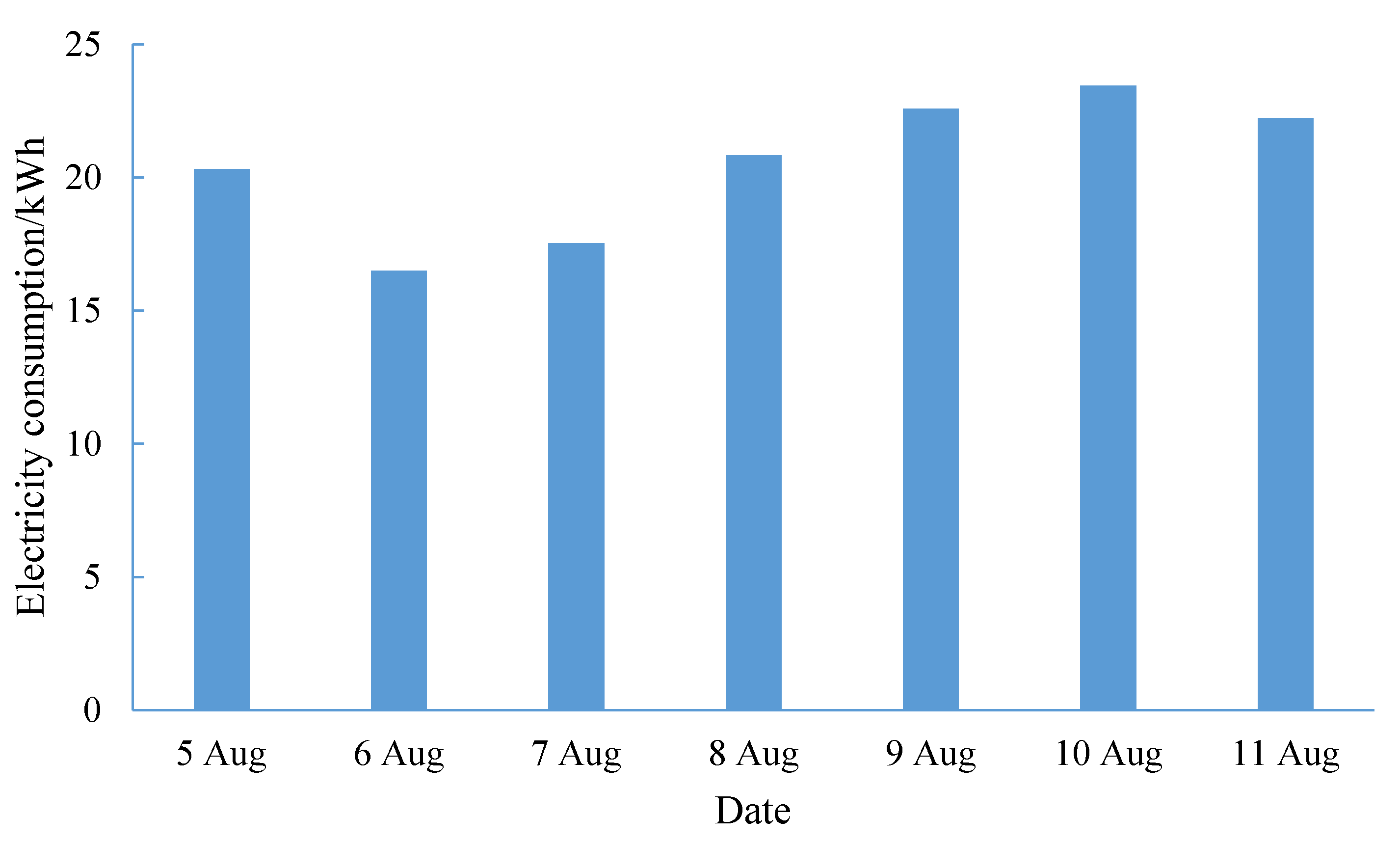
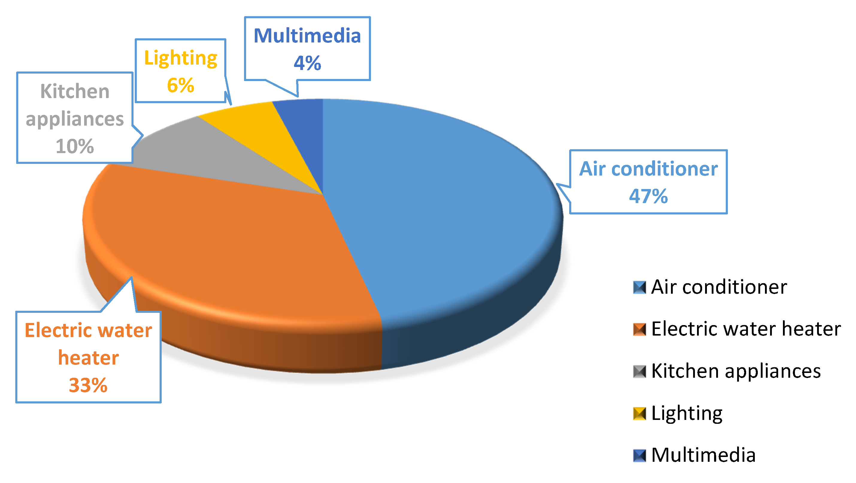
The electricity consumption of a user in the smart community from 5–11 August in 2019 is shown in Figure 2, and the electricity consumption of each household equipment is depicted in Figure 3. It can be seen from Figure 2 that the electricity consumption of this user remained basically stable in a week, and the electricity consumption at the weekend increased compared to the working day. The maximum daily electricity consumption reached 23.44 kW h, since the residential community is mainly composed of villas. It can be concluded from Figure 3 that the electricity consumption of air conditioning accounts for up to 47% of the total electricity consumption, indicating that the air conditioning load has great potential for DR. Besides, there is little EV in this community, so only air conditioning is considered in this part.

6.1.2. Analysis on DR of Residential Load

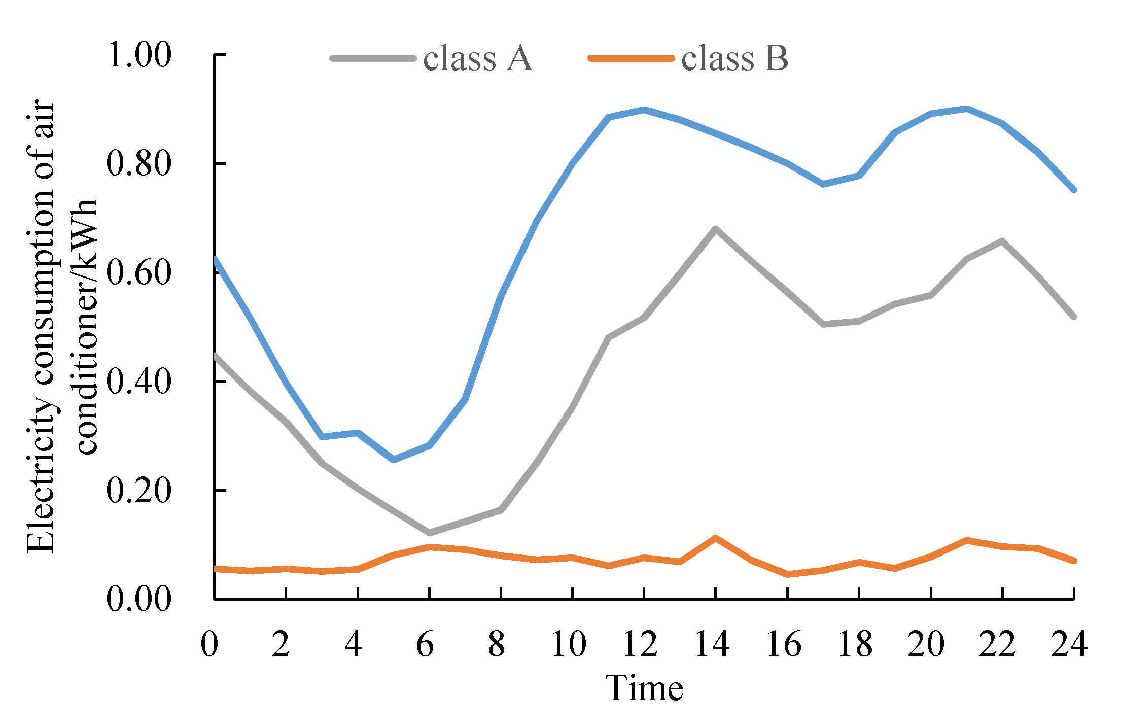
In order to further analyze the DR potential of air conditioning load, the air conditioning load of 40 users in this smart community is selected for analysis. The air conditioning load curve can be roughly categorized into three classes, as depicted in Figure 4, and its daily load rate is shown in Table 1. Combined with Figure 4 and Table 1, it can be found that the air conditioning load characteristics of the three types of users are different from each other. The load curve of class A users have two peaks and two valleys, the peak of electricity consumption occurs at 14:00 and 22:00, and the daily load rate is relatively low, and therefore they have a great potential for DR. The power consumption of air conditioner of class B load in one day is almost zero, which has no potential of load control. Class C users are similar to class A, both of which show two peaks and two valleys, but the load rate of former one is relatively high, and they have a certain staggered peak response capability.
Among the 40 users in the smart community, the daily load curves of class A and class C users before and after participating in DR are shown in Figure 5. Both load peaks are reduced to a certain extent, the peak load decreases from 76.38 to 69.01 kW.

6.2. Case 2

6.2.1. Simulation Settings

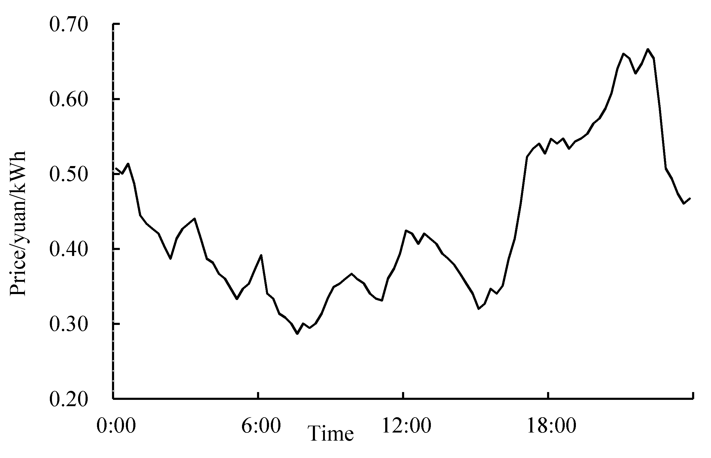
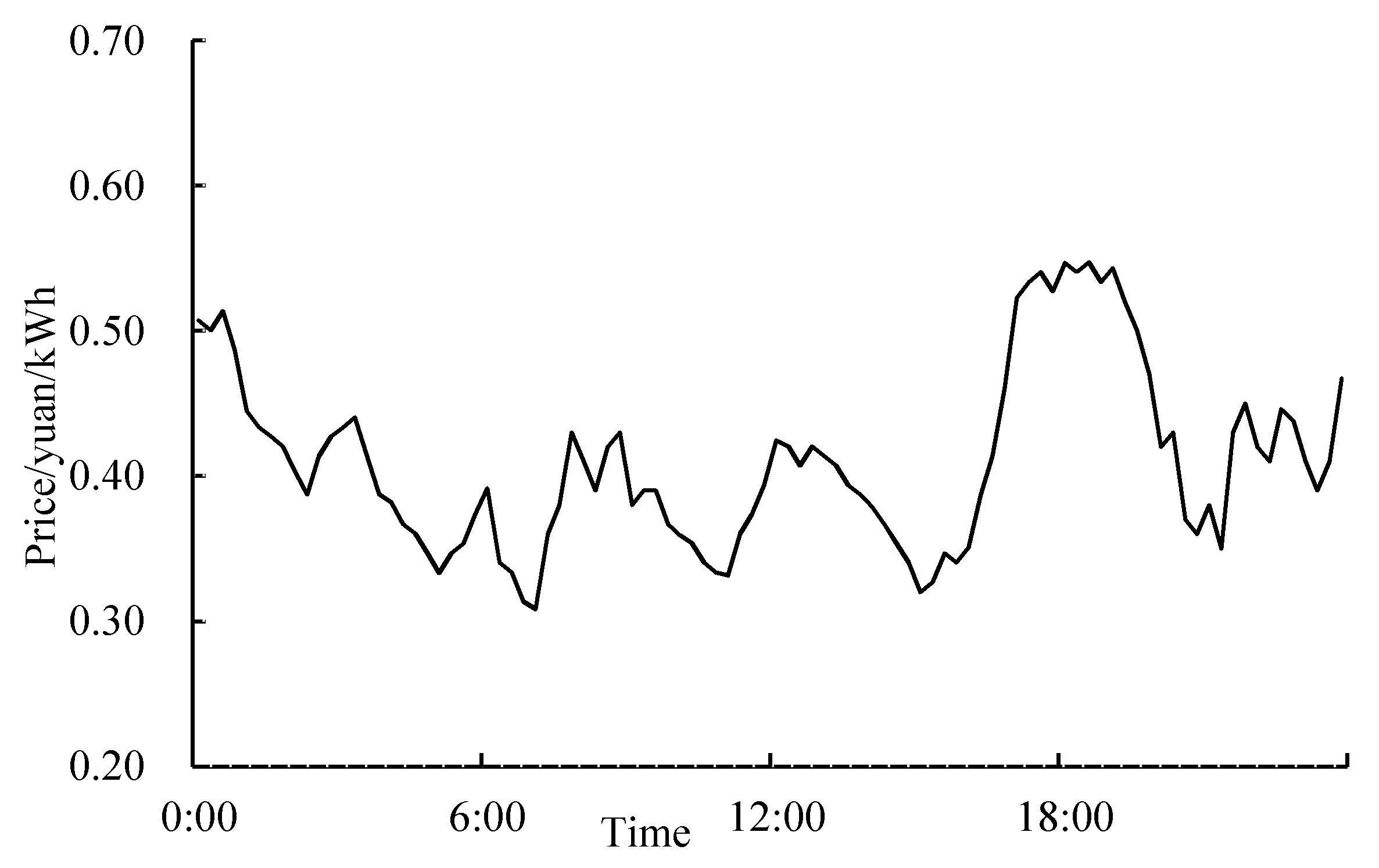
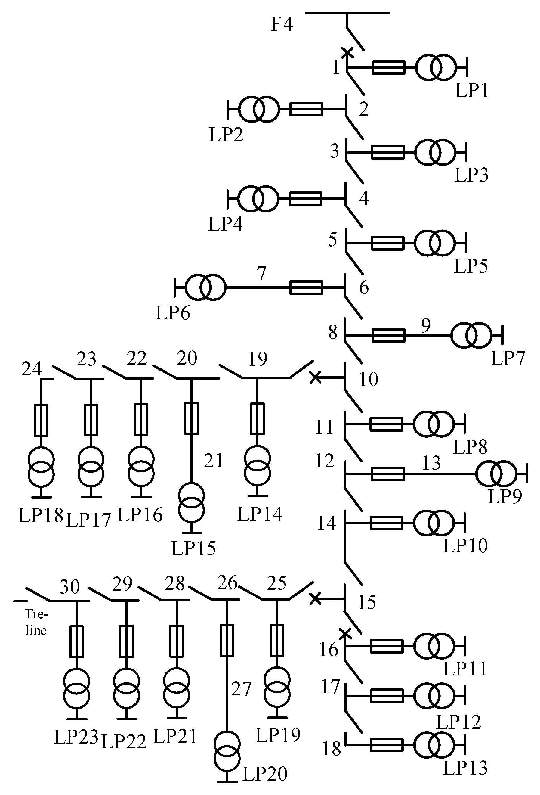
A modified RBTS-BUS 6 system is employed as the test system, in which the maximum power provided by the feeder F4 is 12 MW, and the transfer capacity of the tie line is 6 MW. As shown in Figure 6, the network frame includes 30 lines, 23 load points, 4 circuit breakers, and 21 load switches. The feeder length and load point data can be found in [32]. The circuit breakers, load switches, and fuses are assumed to be 100% reliable. The fault isolation time is 0.5 h, and the sum of fault isolation and load transfer time is 1 h. According to the current design requirements of distribution network capacity in residential areas, the capacity of each household is 8 kW, and the simultaneous factor is set at 0.5. The maximum power provided by the feeder F4 is 12 MW; therefore, there are about 3000 households in this area. The average EV inventory per household is set to 0.1, and all participate in DR. The air conditioning inventory per household is set to 2 and the proportion of air conditioning participating in DR is 0.2 considering the user’s demand for comfort. The charging power and battery capacity of EVs is 5 kW and 40 kW·h, respectively. The energy consumption of EVs for traveling 100 km is 18 kW·h, and the battery charging efficiency is set to 0.9. It is assumed that the access time, departure time, and SOC of EVs are normally distributed, and could be obtained by employing Monte Carlo sampling. The highest and lowest running frequency of inverter air conditioning is 100 Hz and 20 Hz, respectively. R and C are specified as 5.56 °C/kW and 0.18 (kW h)/°C, respectively. The air conditioning power coefficient and the refrigerating capacity coefficient can be found in [33]. It is assumed that air conditioning cools in summer and heats in winter, and the comfort air conditioning interval is set to [22 °C, 28 °C]. The daily maximum dispatchable number is limited to 2 during the peak load period. The load data is shown in Appendix A, Table A1, and it is assumed that the load at each load point varies proportionally with the implementation of DR. The real-time electricity price curve is displayed in Appendix A, Figure A1. AMPL/CPLEX, an efficient commercial solver, is adopted to solve the proposed DR model, then the daily load curve considering DR of household equipment is obtained. Subsequently, the annual load curve considering DR could be determined according to the annual–weekly load curve and the weekly–daily load curve. Afterwards, the annual load curve is clustered, and the Monte Carlo simulation method is employed to calculate the reliability index of the distribution network [34].

6.2.2. Load Profile Considering DR

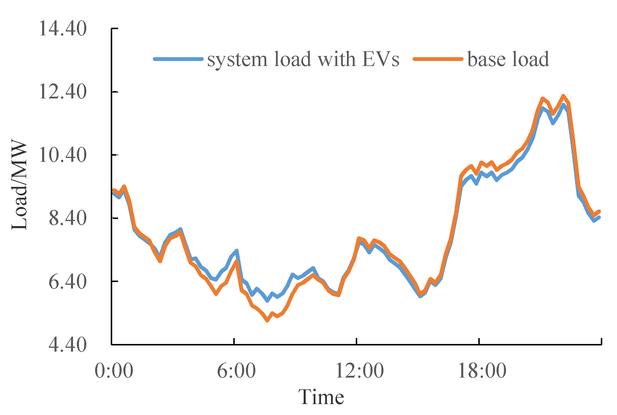
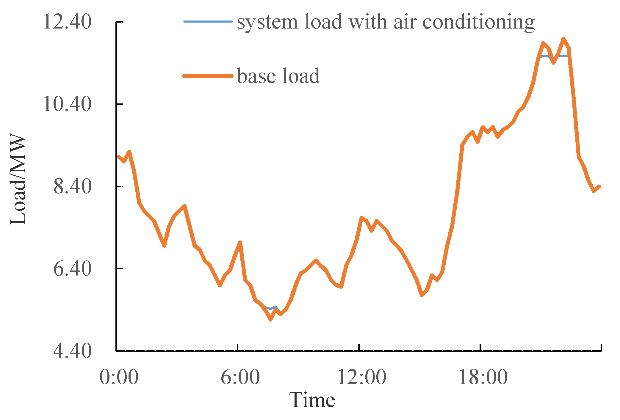
The daily load curve with and without EVs participating in DR is shown in Figure 7. It can be found that EV owners transfer the charging loads from the period of high electricity price to the period of low electricity price under the guidance of real-time electricity price, achieving peak load shaving and valley filling. The daily load curve with and without the air conditioning participating in DR is depicted in Figure 8. It can be found that the peak load is reduced and the load curve can be smoothed through the frequency reduction of air conditioning in the peak load period.
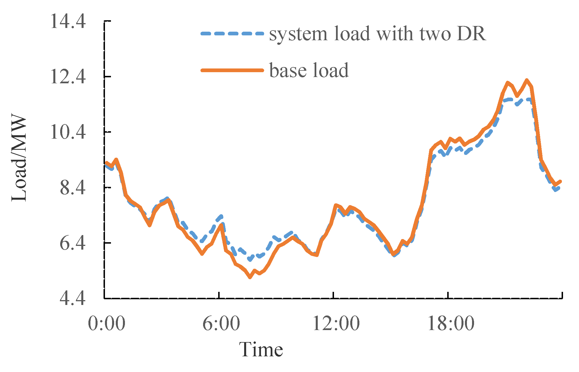
The daily load curve considering DR of EVs based on electricity price and air conditioning based on incentives is shown in Figure 9. It can be found that the load considering DR decreases during the peak period, and increases during the valley period compared to the base load, thus achieving peak load shaving and valley filling. Besides, the daily load peak without DR appears at 22:15, and the peak load is 12.27 MW. Considering the limitation of feeder capacity, part of the loads should be cut off. The daily load peak with DR appears at 22:30, and the maximum load is 11.57 MW, which satisfies the supply capacity constraints of feeders.

6.2.3. Influence of Real-Time Electricity Price on DR

The real-time electricity price, which has a certain randomness, is formulated according to the day-ahead load prediction, and plays the role of guiding electricity consumption. Considering the load uncertainty, a certain deviation between the actual electricity load and the predicted load may occur. Given this situation, applying the real-time electricity price shown in Appendix A, Figure A2, the daily load curve with and without EVs participating in the DR is shown in Figure 10. It can be found that the daily load peak appears at 21:00, because the real-time electricity in this period is relatively lower than others. Also, the daily load curve during the period of 17:00 to 18:45 is reduced, which is not the actual peak period needing to be clipped. Therefore, DR based on electricity price has a certain randomness and is greatly affected by real-time electricity price. Unreasonable real-time electricity price may lead to “peak-on-peak” or unnecessary load reduction.

6.2.4. Reliability Evaluation Considering DR

In this paper, four cases are conducted to evaluate the reliability of the distribution network considering DR. The annual load curve is composed of 8760 load points, which can be divided into 712 clusters, for there are 712 different points. The final system reliability evaluation indexes can be determined with the calculation results and weighted values of each cluster.
  • Case 1: DR is not taken into consideration.
  • Case 2: DR based on electricity price and incentive is considered.
  • Case 3: Case 1 with sufficient spare capacity of tie lines.
  • Case 4: Case 2 with sufficient spare capacity of tie lines.
  • The reliability index of the four cases is shown in Table 2.
By comparing the reliability indexes of cases 1 and 2, it can be concluded that DR can effectively improve the system reliability indexes. With DR, the peak load decreases 5.7%, the indexes of SAIDI, CAIDI, and ENS decrease 7.4%, 5.5%, and 12.7%, respectively. The main reason is that DR based on electricity price can transfer the loads from peak period to valley period to reduce the peak load of the system, and DR based on incentive can directly reduce part of the loads at the peak period, thus reducing the probability of power supply shortage of the distribution system. On the other hand, if a fault occurs during the peak period, the reduced loads considering DR can increase the transfer probability of the loads after fault isolation, thus reducing the average interruption frequency and interruption duration at the load point. Therefore the SAIFI, SAIDI, and ENS indexes are improved. By comparing cases 3 and 4, it can be found that when the capacity of the tie line is infinite, DR has no impact on the SAIFI and SAIDI indexes, and only the ENS index is improved due to the reduced peak load.

7. Conclusions

In this paper, two kinds of typical household electrical equipment are considered to participate in DR. DR models based on electricity price and incentive are proposed to obtain load curves with different DR mechanisms taken into account. Considering the transmission capacity limit of tie lines, a reliability evaluation method is proposed considering power supply capacity shortage. The following conclusions can be drawn from the simulation results:
(1)
DR can improve the load curve and reduce the peak loads. DR based on electricity price has a certain randomness and is greatly affected by real-time electricity price. Unreasonable real-time electricity price may lead to “peak-on-peak” or unnecessary load reduction.
(2)
Both DR based on electricity price and DR based on incentive can improve the reliability index of distribution networks. Compared with the reliability results attained by employing a single DR strategy, comprehensive DRs can improve reliability
(3)
DR has no influence on the distribution network reliability index if transmission capacity of tie lines is assumed to be infinite. Under the premise of considering the tie line capacity limit, DR reduces the peak loads of the systems and decreases the probability of insufficient power supply capacity in normal operation, and meanwhile increases the possibility of the load point being transferred when a failure occurs.

Author Contributions

All the authors contributed to this work. H.C., J.T., and Y.M. conceived and structured the study, X.W. and J.Z. prepared the preliminary manuscript, L.S. reviewed and finalized the manuscript.

Funding

This research was funded by State Grid Suzhou Power Supply Company.

Acknowledgments

This work was supported by the Comprehensive Demonstration Project of Distribution Internet of Things in Suzhou Historic District.

Conflicts of Interest

The authors declare no conflicts of interest.

Appendix A

Table A1. Load data.
Load Number (Class)Average Load (kW)Load Number (Class)Average Load (kW)Load Number (Class)Average Load (kW)Load Number (Class)Average Load (kW)
LP1(II)165.9LP7(I)210.1LP13(III)250.1LP19(III)155.4
LP2(III)180.8LP8(III)155.4LP14(III)155.4LP20(II)186.1
LP3(III)250.1LP9(I)283.1LP15(II)186.1LP21(I)283.1
LP4(III)243.1LP10(II)158.5LP16(II)158.5LP22(II)158.5
LP5(I)207.0LP11(III)155.4LP17(III)250.1LP23(I)210.1
LP6(II)165.9LP12(II)158.5LP18(III)243.1
Figure A1. Real-time electricity price curve.
Processes 07 00799 g0a1
Figure A2. Real-time electricity price curve.
Processes 07 00799 g0a2

References

  1. Eissa, M.M. Developing incentive demand response with commercial energy management system (CEMS) based on diffusion model, smart meters and new communication protocol. Appl. Energy 2019, 236, 273–292. [Google Scholar] [CrossRef]
  2. Vahedipour-Dahraie, M.; Najafi, H.; Anvari-Moghaddam, A.; Guerrero, J. Study of the effect of time-based rate demand response programs on stochastic day-ahead energy and reserve scheduling in islanded residential microgrids. Appl. Sci. 2017, 7, 378. [Google Scholar] [CrossRef]
  3. Pinson, P.; Madsen, H. Benefits and challenges of electrical demand response: A critical review. Renew. Sustain. Energy Rev. 2014, 39, 686–699. [Google Scholar]
  4. Wang, F.; Zhou, L.; Ren, H.; Liu, X.; Talari, S.; Shafie-khah, M.; Catalão, J.P. Multi-objective optimization model of source-load-storage synergetic dispatch for building energy system based on TOU price demand response. IEEE Trans. Ind. Appl. 2018, 54, 1017–1028. [Google Scholar] [CrossRef]
  5. Sharifi, R.; Anvari-Moghaddam, A.; Fathi, S.H.; Guerrero, J.M.; Vahidinasab, V. Economic demand response model in liberalised electricity markets with respect to flexibility of consumers. IET Gener. Transm. Distrib. 2017, 11, 4291–4298. [Google Scholar] [CrossRef] [Green Version]
  6. Deng, R.; Yang, Z.; Chow, M.Y.; Chen, J.M. A survey on demand response in smart grids: Mathematical models and approaches. IEEE Trans. Ind. Inform. 2015, 11, 570–582. [Google Scholar] [CrossRef]
  7. Yu, M.; Hong, S.H.; Ding, Y.; Ye, H. An incentive-based demand response (DR) model considering composited DR resources. IEEE Trans. Ind. Electro. 2018, 66, 1488–1498. [Google Scholar] [CrossRef]
  8. Zhou, B.R.; Huang, Y.C.; Zhang, Y.J. Reliability analysis on microgrid considering incentive demand response. Autom. Electr. Power Syst. 2017, 41, 70–78. [Google Scholar]
  9. Brahman, F.; Honarmand, M.; Jadid, S. Optimal electrical and thermal energy management of a residential energy hub, integrating demand response and energy storage system. Energy Build. 2015, 90, 65–75. [Google Scholar] [CrossRef]
  10. Sharifi, R.; Moghaddam, A.A.; Fathi, S.H.; Vahidinasab, V. A flexible responsive load economic model for industrial demands. Processes 2019, 7, 147. [Google Scholar] [CrossRef]
  11. Sharifi, R.; Fathi, S.H.; Vahidinasab, V. A review on demand-side tools in electricity market. Renew. Sustain. Energy Rev. 2017, 72, 565–572. [Google Scholar] [CrossRef]
  12. Aalami, H.A.; Moghaddam, M.P.; Yousefi, G.R. Modelling and prioritizing demand response programs in power markets. Electr. Power Syst. Res. 2010, 80, 426–435. [Google Scholar] [CrossRef]
  13. Smith, R.; Meng, K.; Dong, Z.; Simpson, R. Demand response: A strategy to address residential air-conditioning peak load in Australia. J. Mod. Power Syst. Clean Energy 2013, 1, 223–230. [Google Scholar] [CrossRef]
  14. Reynolds, S.P.; Creighton, T.E. Time-of-use rates for very large customers on the pacific gas and electric company system. IEEE Trans. Power Appar. Syst. 1980, 99, 147–151. [Google Scholar] [CrossRef]
  15. Kai, M.; Hu, G.; Spanos, C.J. A cooperative demand response scheme using punishment mechanism and application to industrial refrigerated warehouses. IEEE Trans. Ind. Inform. 2015, 11, 1520–1531. [Google Scholar]
  16. Chen, C.; Kishore, S.; Wang, Z.; Alizadeh, M.; Scaglione, A. How will Demand Response aggregators affect electricity markets ?—A Cournot game analysis. In Proceedings of the 5th International Symposium on Communications Control and Signal Processing (ISCCSP), Roma, Italy, 2–4 May 2012; pp. 1–6. [Google Scholar]
  17. Zeng, B.; Jiang, W.Q.; Yang, Z.; Li, G. Optimal load dispatching method based on chance-constrained programming for household electrical equipment. Autom. Electr. Power Syst. 2018, 38, 27–33. [Google Scholar]
  18. Chen, Z.; Li, Y.Q.; Leng, Z.Y.; Lu, G.X. Refined modeling and energy management strategy of typical household high-power loads. Autom. Electr. Power Syst. 2018, 42, 135–143. [Google Scholar]
  19. Sharifi, R.; Anvari-Moghaddam, A.; Fathi, S.H.; Guerrero, J.M.; Vahidinasab, V. An optimal market-oriented demand response model for price-responsive residential consumers. Energy Eff. 2019, 12, 803–815. [Google Scholar] [CrossRef]
  20. Tushar, M.H.K.; Assi, C.; Maier, M.; Uddin, M.F. Smart microgrids: Optimal joint scheduling for electric vehicles and home appliances. IEEE Trans. Smart Grid 2014, 5, 239–250. [Google Scholar] [CrossRef]
  21. Khalid, A.; Javaid, N.; Guizani, M.; Alhussein, M.; Aurangzeb, K.; Ilahi, M. Towards dynamic coordination among home appliances using multi-objective energy optimization for demand side management in smart buildings. IEEE Access 2018, 6, 19509–19529. [Google Scholar] [CrossRef]
  22. Mohajeryami, S.; Moghaddam, I.N.; Doostan, M.; Vatani, B.; Schwarz, P. A novel economic model for price-based demand response. Electr. Power Syst. Res. 2016, 135, 1–9. [Google Scholar] [CrossRef]
  23. Mnatsakanyan, A.; Kennedy, S.W. A novel demand response model with an application for a virtual power plant. IEEE Trans. Smart Grid 2015, 6, 230–237. [Google Scholar] [CrossRef]
  24. Zhao, H.S.; Wang, Y.Y.; Chen, S. Impact of DR on distribution system reliability. Autom. Electr. Power Syst. 2015, 39, 49–55. [Google Scholar]
  25. Zhang, Y.B.; Ren, S.J.; Yang, X.D.; Bao, K.K.; Xie, L.Y.; Qi, J. Optimal configuration considering price-based demand response for stand-alone microgrid. Electr. Power Autom. Equip. 2017, 37, 55–62. [Google Scholar]
  26. Qi, X.J.; Cheng, Q.; Wu, H.B.; Yang, S.H.; Li, Z.X. Impact of incentive-based DR on operational reliability of distribution network. Trans. China Electrotech. Soc. 2018, 33, 5319–5326. [Google Scholar]
  27. Sharifi, R.; Fathi, S.H.; Vahidinasab, V. Customer baseline load models for residential sector in a smart-grid environment. Energy Rep. 2016, 2, 74–81. [Google Scholar] [CrossRef] [Green Version]
  28. Niu, W.J.; Li, Y.; Wang, B.B. Demand Response Based Virtual Power Plant Modeling Considering Uncertainty. Proc. CSEE 2014, 34, 3630–3637. [Google Scholar]
  29. Lei, M.; Wei, W.; Zeng, J.H.; Mo, S.Y. Effect of load control on power supply reliability considering demand response. Autom. Electr. Power Syst. 2018, 42, 53–59. [Google Scholar]
  30. Yang, J.R.; Shi, K.; Cui, X.Q.; Gao, C.W.; Cui, G.Y.; Yang, J.L. Peak Load Reduction Method of Inverter Air-conditioning Group Under DR. Autom. Electr. Power Syst. 2018, 42, 44–56. [Google Scholar]
  31. Kwac, J.; Flora, J.; Rajagopal, R. Household energy consumption segmentation using hourly data. IEEE Trans. Smart Grid 2014, 5, 420–430. [Google Scholar] [CrossRef]
  32. Billinton, R.; Jonnavithula, S. A test system for teaching overall power system reliability assessment. IEEE Trans. Power Syst. 1996, 11, 1670–1676. [Google Scholar] [CrossRef]
  33. Cao, X.L.; Yu, S.X.; Li, X.L.; Wang, W.; Liao, S.M. Theoretic and experimental study on domestic air-conditioner with R410A as refrigerant. J. Cent. South Univ. (Sci. Technol.) 2010, 41, 759–763. [Google Scholar]
  34. Transmission and Distribution Committee. IEEE Guide for Electric Power Distribution Reliability Indices Redline; IEEE: NY, USA, 2012. [Google Scholar]
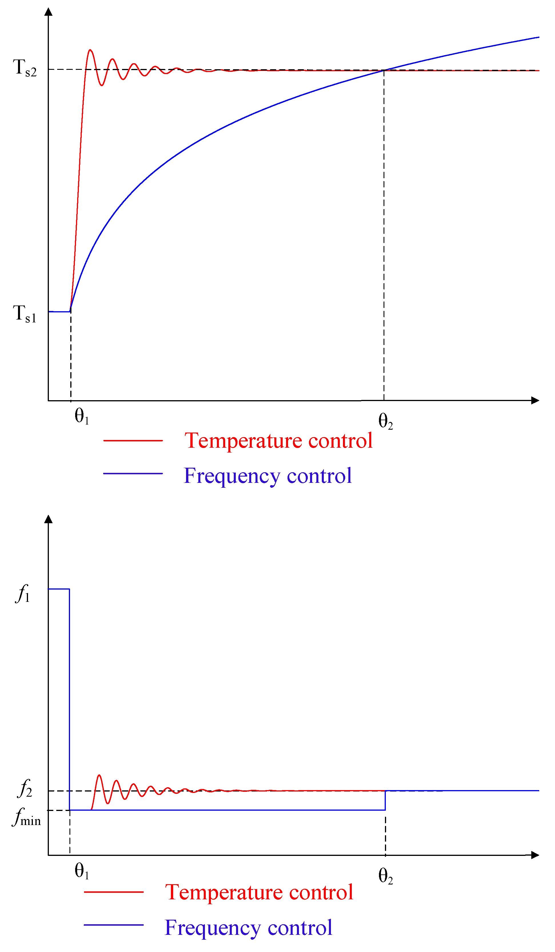
Figure 1. Schematic diagram of different control methods.
Processes 07 00799 g001
Figure 2. Residential electricity consumption in a week.
Processes 07 00799 g002
Figure 3. Household electricity composition analysis.
Processes 07 00799 g003
Figure 4. Air conditioning load curve of different classes.
Processes 07 00799 g004
Figure 5. Comparison of load profile between base loads and loads with demand response (DR) taken into account.
Processes 07 00799 g005
Figure 6. Topology of the test network.
Processes 07 00799 g006
Figure 7. Comparison of load profile between base loads and loads with electric vehicles (EVs) taken into account
Processes 07 00799 g007
Figure 8. Comparison of load profile between base loads and loads with air conditioning taken into account.
Processes 07 00799 g008
Figure 9. Comparison of load profile between base loads and loads with DR taken into account.
Processes 07 00799 g009
Figure 10. Comparison of load profile between base loads and loads with EVs taken into account.
Processes 07 00799 g010
Table 1. Daily load rate.
TypeDaily Load RatePercent
A0.63325356%
B0.64760911%
C0.7498433%
Table 2. System reliability index (SAIFI, system average interruption frequency index; SAIDI, system average interruption duration index; CAIDI, customer average interruption duration index; ENS, energy not supplied).
CaseSAIFI/(times/a)SAIDI/(h/a)CAIDI/(h/times)ENS/(MW h/a)
12.2535.672.51767.93
22.20525.24832.379859.31
32.20523.5191.59643.22
42.20523.5191.59640.76