Article

Research on the Vertical Vibration Characteristics of Hydraulic Screw Down System of Rolling Mill under Nonlinear Friction

1
Hebei Provincial Key Laboratory of Heavy Machinery Fluid Power Transmission and Control, Yanshan University, Qinhuangdao 066004, China
2
National Engineering Research Center for Equipment and Technology of Cold Strip Rolling, Yanshan University, Qinhuangdao 066004, China
3
Heavy-duty Intelligent Manufacturing Equipment Innovation Center of Hebei Province, Yanshan University, Qinhuangdao 066004, China
4
Research Center of Fluid Machinery Engineering and Technology, Jiangsu University, Zhenjiang 212013, China
*
Authors to whom correspondence should be addressed.
Processes 2019, 7(11), 792; https://doi.org/10.3390/pr7110792
Submission received: 31 August 2019 / Revised: 1 October 2019 / Accepted: 15 October 2019 / Published: 2 November 2019
(This article belongs to the Special Issue Smart Flow Control Processes in Micro Scale)

Abstract

:
The rolling mill with hydraulic system is widely used in the production of strip steel. For the problem of vertical vibration of the rolling mill, the effects of different equivalent damping coefficient, leakage coefficient, and proportional coefficient of the controller on the hydraulic screw down system of the rolling mill are studied, respectively. First, a vertical vibration model of a hydraulic screw down system was established, considering the nonlinear friction and parameter uncertainty of the press cylinder. Second, the correlation between different equivalent damping coefficient, internal leakage coefficient, proportional coefficient, vertical vibration was analyzed. The simulation results show that, in the closed-loop state, when Proportional-Integral-Derivative (PID) controller parameters are fixed, due to the change of the equivalent damping coefficient and internal leakage coefficient, the system will have parameter uncertainty, which may lead to the failure of the PID controller and the vertical vibration of the system. This study has theoretical and practical significance for analyzing the mechanism of vertical vibration of the rolling mill.

1. Introduction

With the continuous improvement of strip material properties, high requirements for rolling equipment appears. The increase of rolling speed and rolling force weakens the reliability of original equipment, and vertical vibration of the rolling mill appears in more and more fields. This kind of vibration will cause the thickness difference of the strip steel, which is no longer stable, or the surface of the strip steel will produce vibration marks, the surface quality will become poor [1], and even cause serious production accidents, such as strip breaking. Therefore, vibration detection systems based on acceleration sensors are added in many production lines to avoid production accidents by reconstructing the real-time signal [2] to analyze the vertical vibration and reducing the speed artificially [1]. However, it is difficult to deal with this kind of monitoring in the first time, and, consequently, it is hard to avoid vibration.
It is found that vertical vibration of the rolling mill has many inducements, but it is more related to the hydraulic system [3,4], because the hydraulic screw down system is the power source in the vertical direction of the mill [5]. Figure 1 shows that the rolling force is generated by applying the screw down cylinder to the roll system. Moreover, the hydraulic system itself is composed of many nonlinear links [6,7,8]; the hydraulic pump, as an oil-source system, is a vibration source [9], and the working mechanism of the plunger pump will make the system oil-source pressure pulsation [10,11,12,13]. The valve orifice characteristics of the hydraulic system are also nonlinear [14,15]. As the actuator of the hydraulic screw down system, the hydraulic cylinder has a large diameter and long stroke due to its own structure. Due to processing or sealing, the hydraulic cylinder will be affected by obvious nonlinear friction [16,17] and oil leakage. Moreover, the hydraulic cylinder oil also has nonlinear spring-force action [18]. All these factors result in making the hydraulic screw down system work unstable. Therefore, the comprehensive consideration of the nonlinear factors of the hydraulic screw down system and roll system to establish a precise model [19,20,21] is very important and of theoretical significance.
Among those inducements, nonlinear friction widely exists in mass-spring model sliding on the transmission belt [22], pin sliding on the rotating disc, turbine blade, water-lubricated bearing, wheel-rail system, disc braking system, and machine tool system [23]. By establishing nonlinear dynamics models to explain friction phenomena such as stick-slip [24], flutter, and chaos, it can promote the understanding of various friction mechanisms to minimize the deterioration effect of friction. Therefore, it is of theoretical and engineering significance to explore the influence of the hydraulic screw down system’s response to the vertical vibration of the rolling mill under the action of nonlinear friction.
In this paper, the nonlinear vibration model of the hydraulic screw down system is established, considering the influence of nonlinear friction with the LuGre model [16,25]. The closed-loop control system is built by using the Proportional-Integral-Derivative (PID) controller. The influence of the damping coefficient, leakage coefficient, and control proportional coefficient on the vibration characteristics of the system is revealed. The purpose of this work is to clarify the influence of process parameters on the vertical vibration of the rolling mill, with nonlinear friction force taken into account, and to evaluate the influence of vertical vibration by introducing the vibration severity [26,27], which makes the vibration monitoring of the rolling mill in industrial fields more intuitive and can effectively provide the safe and stable operation of equipment.

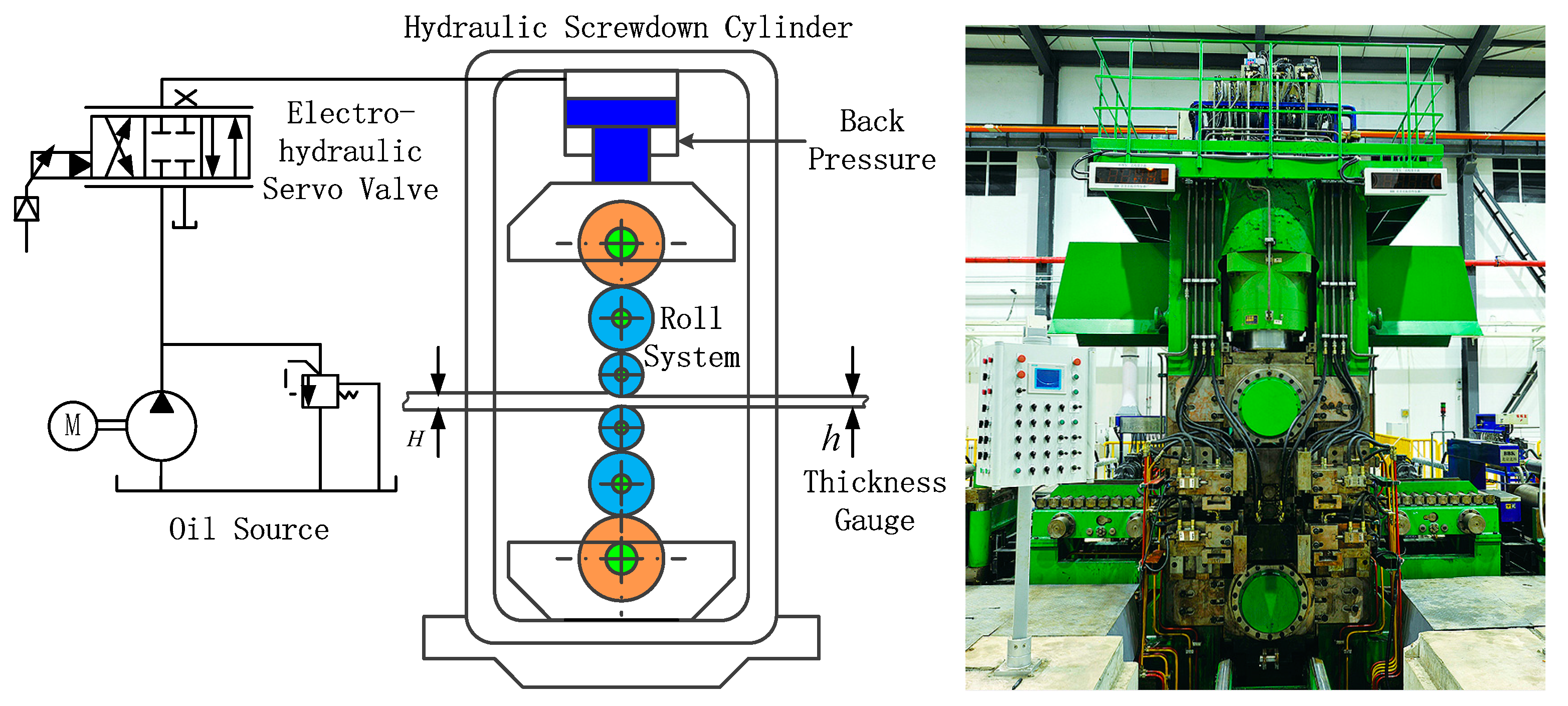
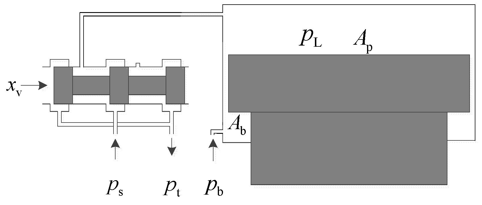
2. Principle of Hydraulic Screw Down System

The structural diagram of the vertical vibration of hydraulic screw down system is shown in Figure 2. x d is the given displacement signal, and x is the cylinder displacement obtained by the displacement sensor. In this paper, in order to study the influence of nonlinear friction F f ( v ) on the vertical vibration of the load roll system, a vertical vibration model of the load roll system was established under the action of nonlinear friction force of the hydraulic screw down system.
The schematic diagram of the hydraulic screw down system of the rolling mill is displayed in Figure 3. p s is the oil-supply pressure, p t is the return pressure, and p b is the back pressure of the rod cavity of hydraulic cylinder. The servo valve is a three-way valve formed by a standard four-way spool valve blocking a control port. When the main spool of the servo valve works in the right position, the high-pressure oil enters into the rod-less cavity of the cylinder, and the piston rod extends to realize the pressing action. When the main spool of the servo valve works in the left position, the high-pressure oil of the rod-less cavity flows back to the oil tank, and the piston rod retracting action is realized under the constant back pressure of the cavity of pole.

3. Mathematical Model

3.1. Nonlinear Flow Equation of Four-Way Valve

The flow equation of the servo valve can be expressed by the following formula [28]:
Q L = C d W x v 2 ( p s p L ) ρ         x v 0
Q L = C d W x v 2 ( p L p t ) ρ         x v < 0
  • C d : port flow coefficient of four-way valve;
  • W : area grades of four-way valve;
  • x v : spool displacement of four-way valve;
  • p L : rod-less cavity pressure of hydraulic cylinder;
  • ρ : oil density.

3.2. Model of Servo Amplifier and Servo Valve

The servo amplifier and servo valve are equivalent to the proportional component, so Equation (2) is applied:
K p 1 = i u
K sv = x v i
  • u : output of vibration controller;
  • K p 1 : gain of the servo amplifier;
  • i : output current of servo amplifier;
  • K sv : gain of servo valve.

3.3. Flow Equation of Hydraulic Cylinder

Ignoring the external leakage characteristics of the hydraulic cylinder has Equation (4) [29]:
Q L = A p x ˙ + C t ( p L p b ) + V β e p ˙ L
where
V = A p L 1 + A p x ;
  • A p : cross-sectional area of rod-less cavity of cylinder;
  • x : vibration displacement of cylinder piston rod;
  • C t : leakage coefficient of hydraulic cylinder;
  • V : rod-less cavity volume of cylinder;
  • L 1 : the initial stroke of the cylinder piston;
  • β e : volume elastic modulus of oil.

3.4. Nonlinear Friction

There are static and dynamic friction models. The LuGre friction model is a kind of dynamic model, which is more reasonable for practical mill system dynamic changes. Moreover, the model can be expressed in simple mathematical form. The parameter identification theory based on this model is mature and more conducive to realize.
The nonlinear friction force of a hydraulic cylinder based on the LuGre model can be expressed by the following equations [30]:
d z d t = v σ 0 z g ( v ) | v |
F f ( v ) = σ 0 z + σ 1 d z d t + σ 2 v
g ( v ) = f c + ( f s f c ) e ( v v s ) 2
where
  • z : average deformation of the sideburns;
  • σ 0 : stiffness coefficient of sideburns;
  • σ 1 : microscopic damping coefficient;
  • σ 2 : viscous damping coefficient;
  • f c : coulomb force of friction;
  • f s : maximum static friction force;
  • v s : Stribeck speed.
The LuGre friction model is composed of Equations (5)–(7), where f c , f s , v s , and σ 2 are static parameters, and σ 0 and σ 1 are dynamic parameters.
(1)
When velocity v = 0 , d z d t = 0 , the friction force is F f ( 0 ) = σ 0 z and is a constant. For the convenience of analysis, the constant is defined as f s , and F ˙ f ( 0 ) = 0 .
(2)
When the velocity v 0 , F f ( v ) can be expressed by Equation (6), and F ˙ f ( v ) is continuously differentiable.

3.5. Balance Equation of Cylinder Piston Force

Considering the influence of nonlinear friction on the piston rod, as shown in Equations (5)–(7), the force balance equation of piston rod is established as follows [31]:
A p p L A b p b = m t x ¨ + c 1 x ˙ + k 1 x + F f ( v ) + F L
where
  • A b : the effective area of rod cavity of cylinder;
  • m t : equivalent total mass of piston and load;
  • c 1 : viscous damping coefficient of piston;
  • k 1 : spring stiffness of load;
  • F f ( v ) : nonlinear friction;
  • F L : external force;
  • v : speed of hydraulic cylinder.

3.6. System State Equation

State variables are defined as follows:
{ x 1 = x x 2 = x ˙ x 3 = x ¨
Then, the system equations can be obtained as follows:
{ x ˙ 1 = x 2 x ˙ 2 = x 3 x ˙ 3 = α 0 x 3 α 1 x 2 α 2 x 1 α 3 f x + α 4 u
Among them are the following equations:
α 0 = C t β e A p L 1 + A p x 1 + c 1 m t , α 1 = β e A p 2 ( A p L 1 + A p x 1 ) m t + β e C t c 1 ( A p L 1 + A p x 1 ) m t + k 1 m t , α 2 = C t k 1 β e ( A p L 1 + A p x 1 ) m t , α 3 = β e A p ( A p L 1 + A p x 1 ) m t , f x = A p L 1 + A p x 1 β e A p F ˙ f ( v ) + C t A p F f ( v ) + C t A p F L b + C t A b A p p C t p b , α 4 = C d W K p 1 K sv β e A p g ( x v ) 2 ρ ( A p L 1 + A p x 1 ) m t , g ( x v ) = p s p L   x v 0 , g ( x v ) = p L p t   x v < 0 .
Due to the influence of different working states and ambient temperature, the equivalent damping coefficient of the system and leakage coefficient in the hydraulic cylinder will be changed during the operation of the system and bring parameter uncertainty of the coefficients of Equation (10), which will affect the working characteristics of the hydraulic system. This phenomenon is discussed in detail in the following.

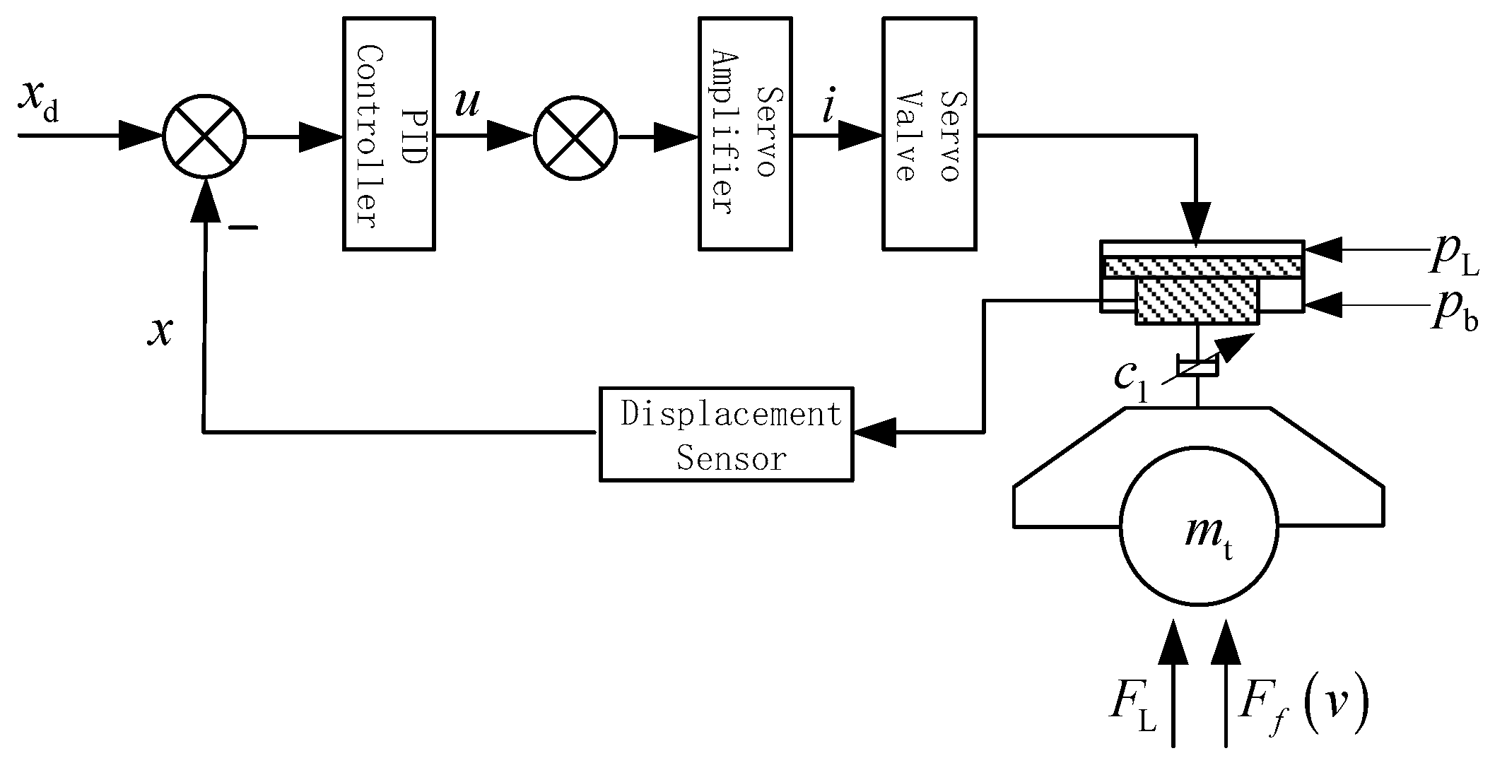
3.7. Vibration Controller

The vibration controller adopts the classical PID control, which can be expressed as Equation (11):
u = K p ( x d x ) + K I ( x d x ) d t + K D d ( x d x ) d t ,
where
  • K P : proportionality coefficient;
  • K I : integral coefficient;
  • K D : differential coefficient.

4. Numerical Simulation

4.1. The Parameters Selection of Simulation Model

The MATLAB is adopted for system modeling and simulation, and ode45 algorithm is employed. Considering that the pressure pulsation caused by the oil pump is 12%, the speed of plunger pump is 990 rpm, the number of plungers is seven, so the pulsation frequency is 116 Hz. The nominal parameters of the hydraulic screw down system of the rolling mill used in the simulation are shown in Table 1.

4.2. Simulation Results and Analysis

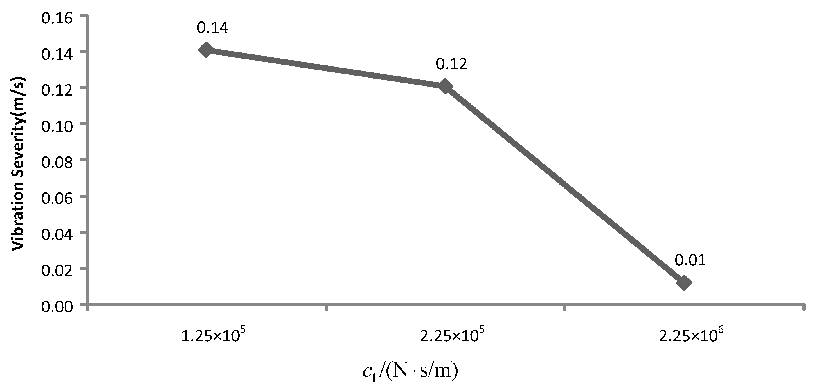
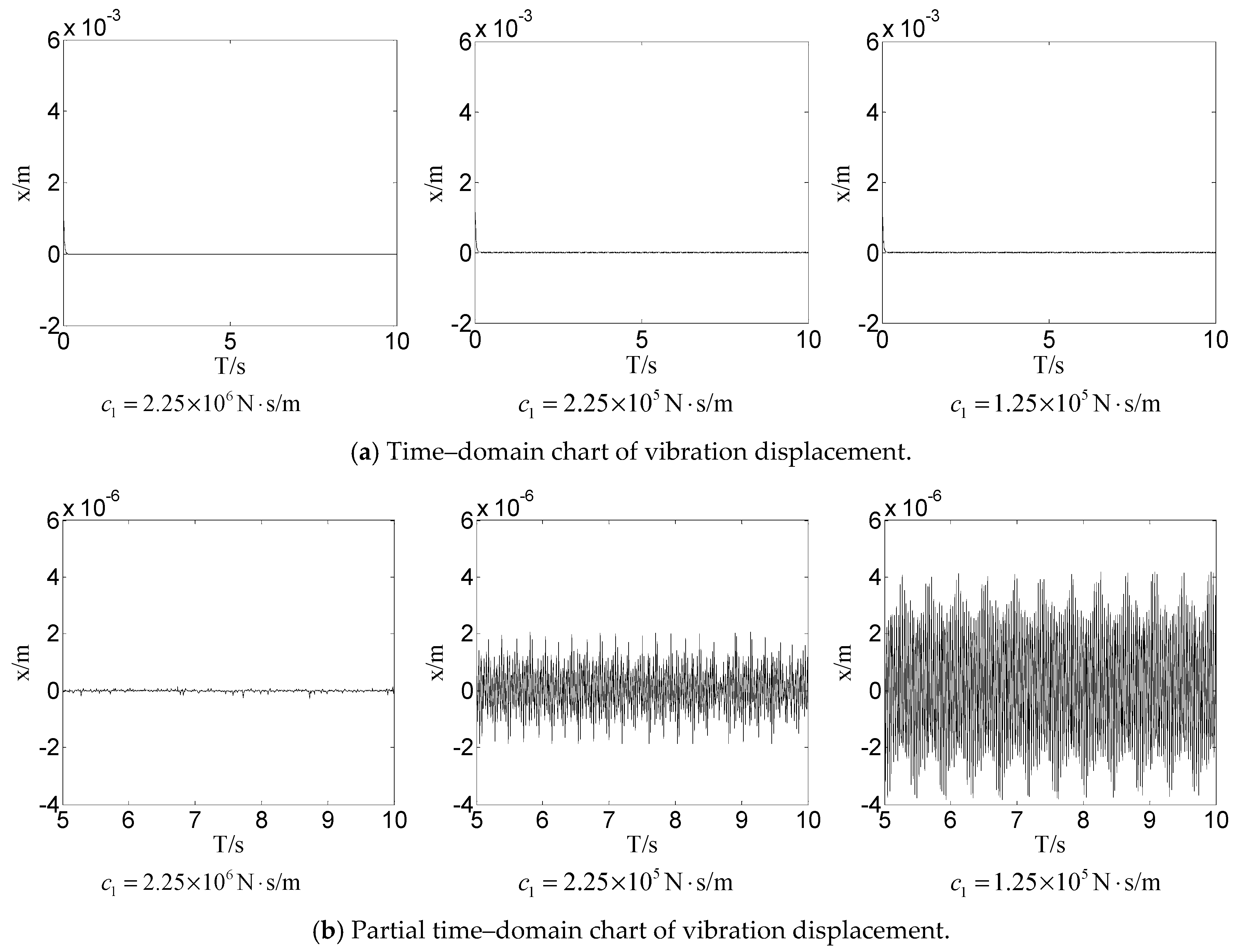
4.2.1. Influence of Different Equivalent Damping Coefficients on Nonlinear Dynamic Behavior

It is found that different equivalent damping coefficients have a great influence on the nonlinear system. At the initial value X 00 = [ 0.001 , 0 , 0 ] , the system damping coefficients are respectively defined as c 1 = 2.25 × 10 6   N s / m , c 1 = 2.25 × 10 5   N s / m , and c 1 = 1.25 × 10 5   N s / m . The time–domain diagrams of the vibration displacement of the cylinder are displayed in Figure 4a,b. The phase diagrams of the vibration displacement–velocity are shown in Figure 4c. An improved frequency–domain integral method [22,23] based on low-frequency filtering of vibration intensity is adopted to obtain the vibration intensity of the system under different damping coefficients. The curve is shown in Figure 5.
Figure 4 shows the vibration simulations that result from the hydraulic cylinder of the rolling mill with different equivalent damping coefficients under the same conditions. Through the vibration displacement curve, it can be clearly found that the vibration amplitude of vibration displacement significantly increases with the damping coefficient decreasing. Through the phase diagram, it can be found that the system moves from a stable state to a periodic vibration state and becomes unstable with the damping coefficient decreasing. From the perspective of vibration intensity, as shown in Figure 5, it can clearly be found that the vibration intensity of the system can be effectively suppressed by increasing the damping.

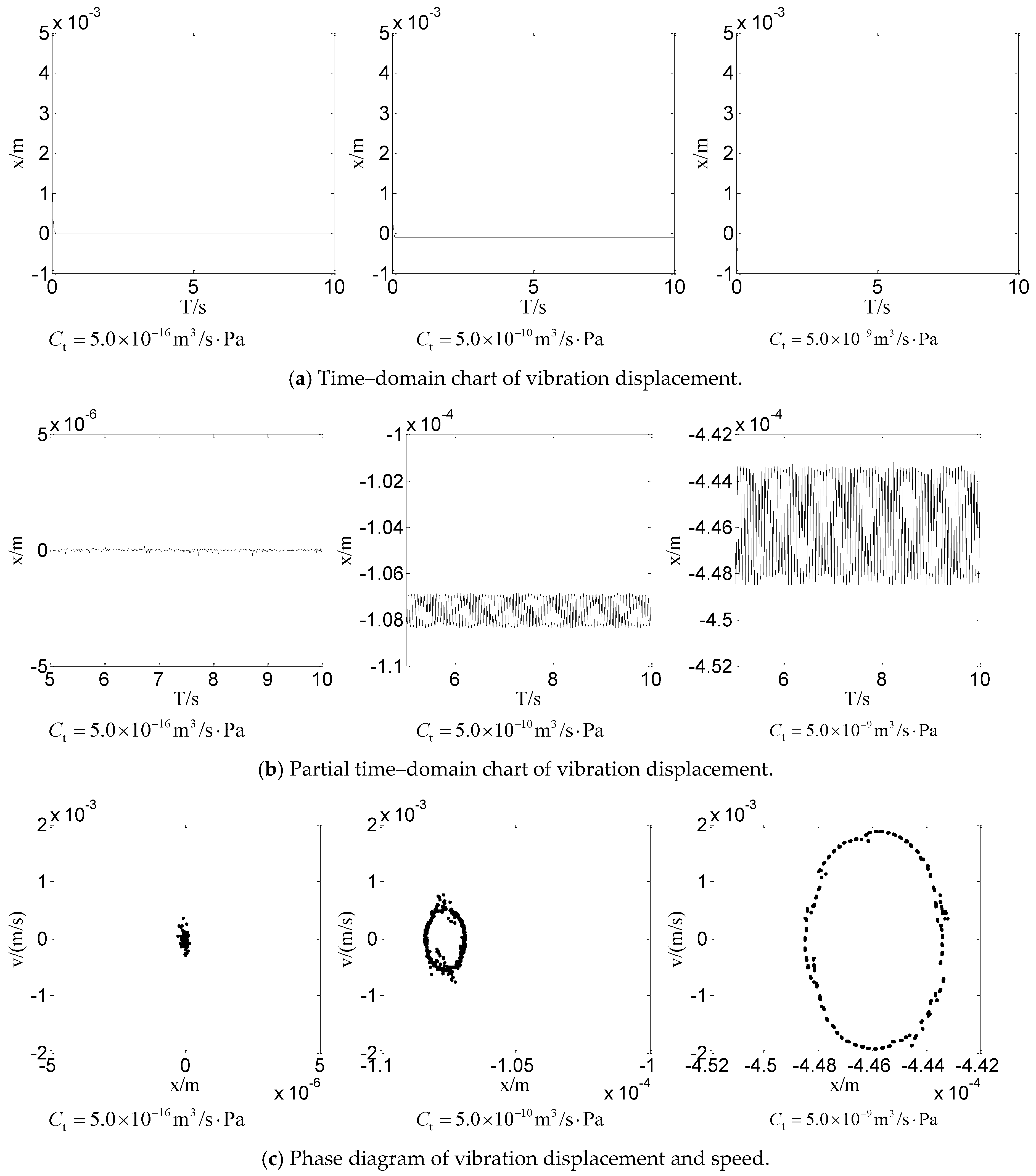
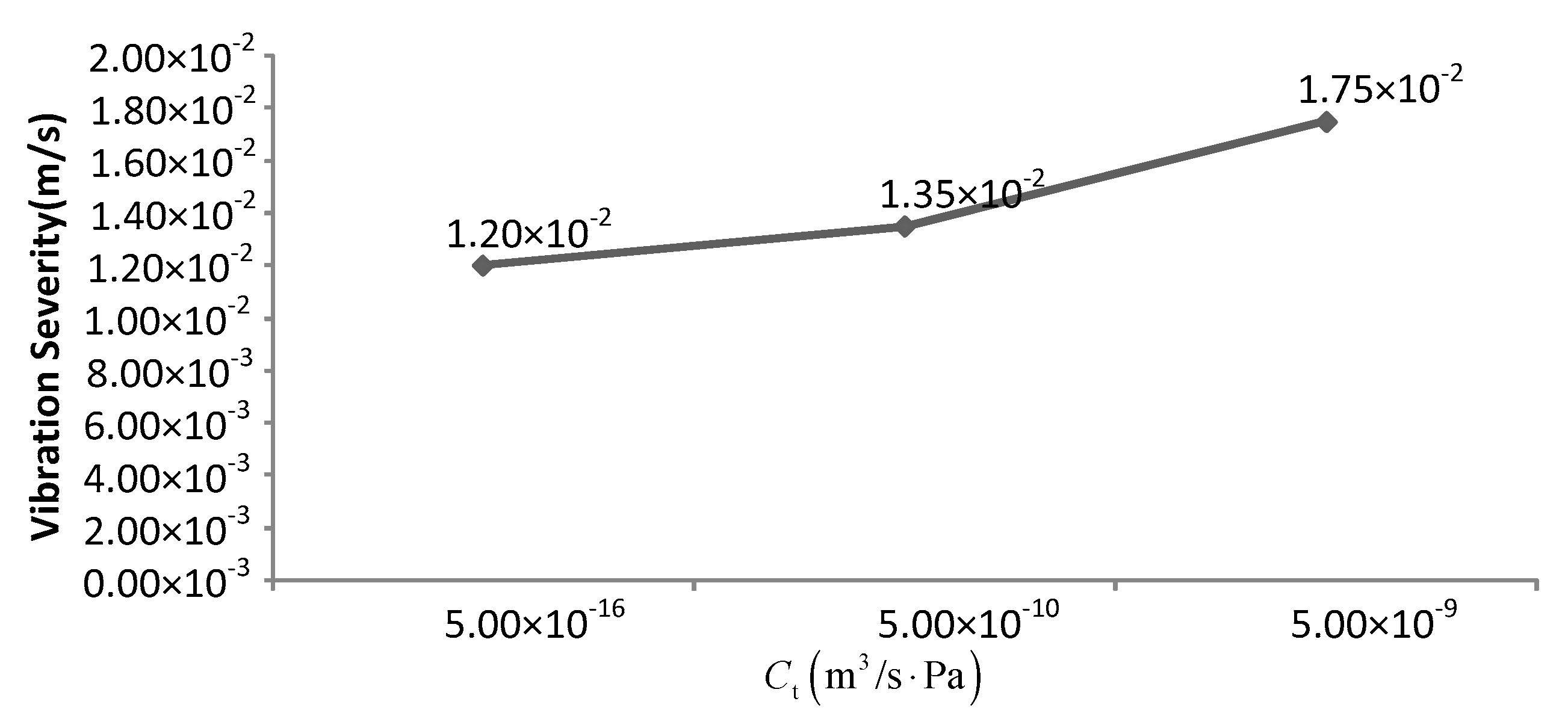
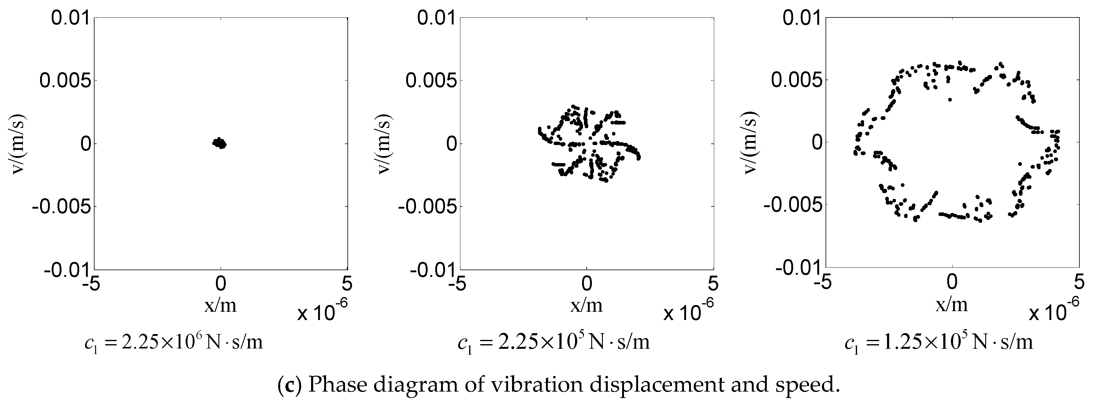
4.2.2. Influence of Different Leakage Coefficients on Nonlinear Dynamic Behavior

The hydraulic system is sealed with a rubber ring. Due to the influence of oil temperature and oil cleanliness, the seal of the hydraulic cylinder will deteriorate with time, resulting in different levels of oil leakage. By studying the influence of different internal leakage coefficients on the system, the vibration mechanism of the hydraulic cylinder caused by the leakage can be analyzed.
The leak coefficients of the hydraulic cylinder are defined as C t = 5.0 × 10 16   m 3 / s Pa , C t = 5.0 × 10 10   m 3 / s Pa , and C t = 5.0 × 10 9 m 3 / s Pa . If you take the initial value X 00 = [ 0.001 , 0 , 0 ] , the time–domain diagram of the vibration displacement of the cylinder and the phase diagram of the vibration displacement–speed are shown in Figure 6. The vibration intensities of the system under different leakage coefficients are displayed in Figure 7.
Figure 6 shows the simulation results of the different leakage coefficients of the hydraulic cylinder under the same other conditions. It can be seen from Figure 6 that the vibration displacement of the hydraulic cylinder is small when the leakage coefficient is small. And from the phase diagram, it can be observed that the system is convergence. By increasing the leakage coefficient of the hydraulic cylinder, the amplitude of the vibration displacement increases. From the phase diagram, it is difficult to stabilize from the convergence to the stage of multi-period vibration. From the variation of vibration intensity in Figure 7, it can be found that the vibration intensity increases with the increase of the leakage coefficient. Therefore, the increase of system leakage will increase the intensity of vertical vibration.

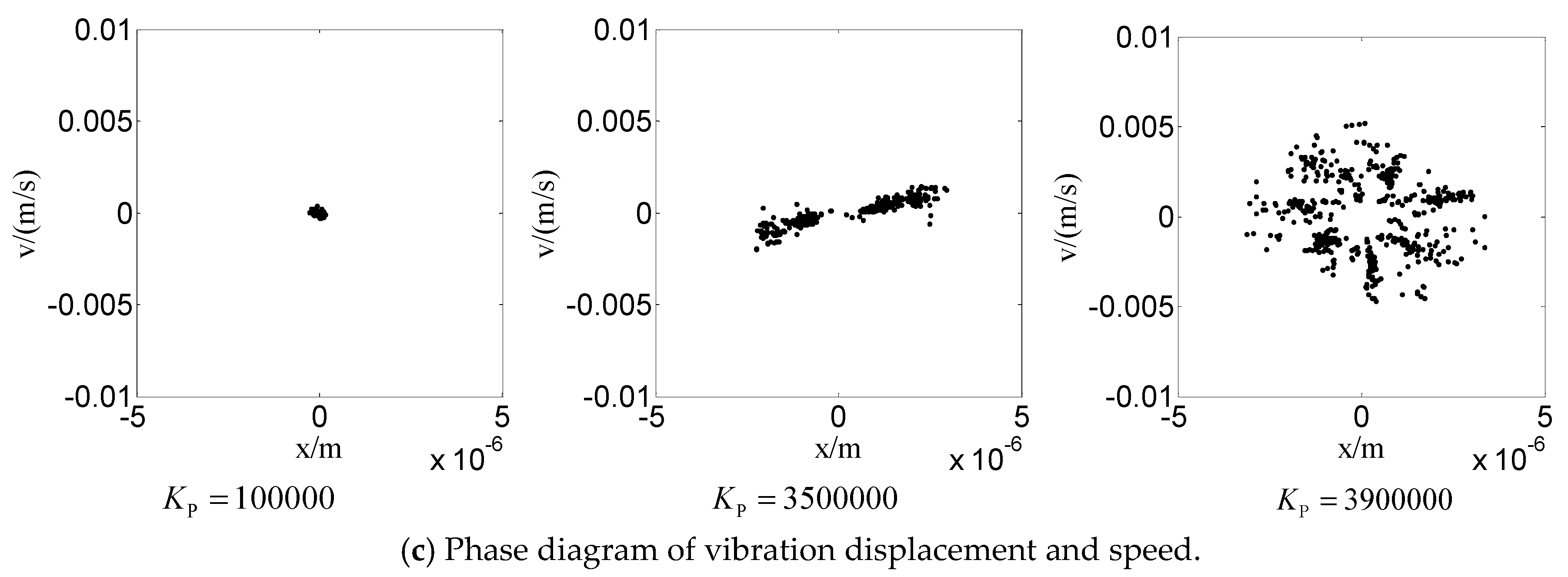
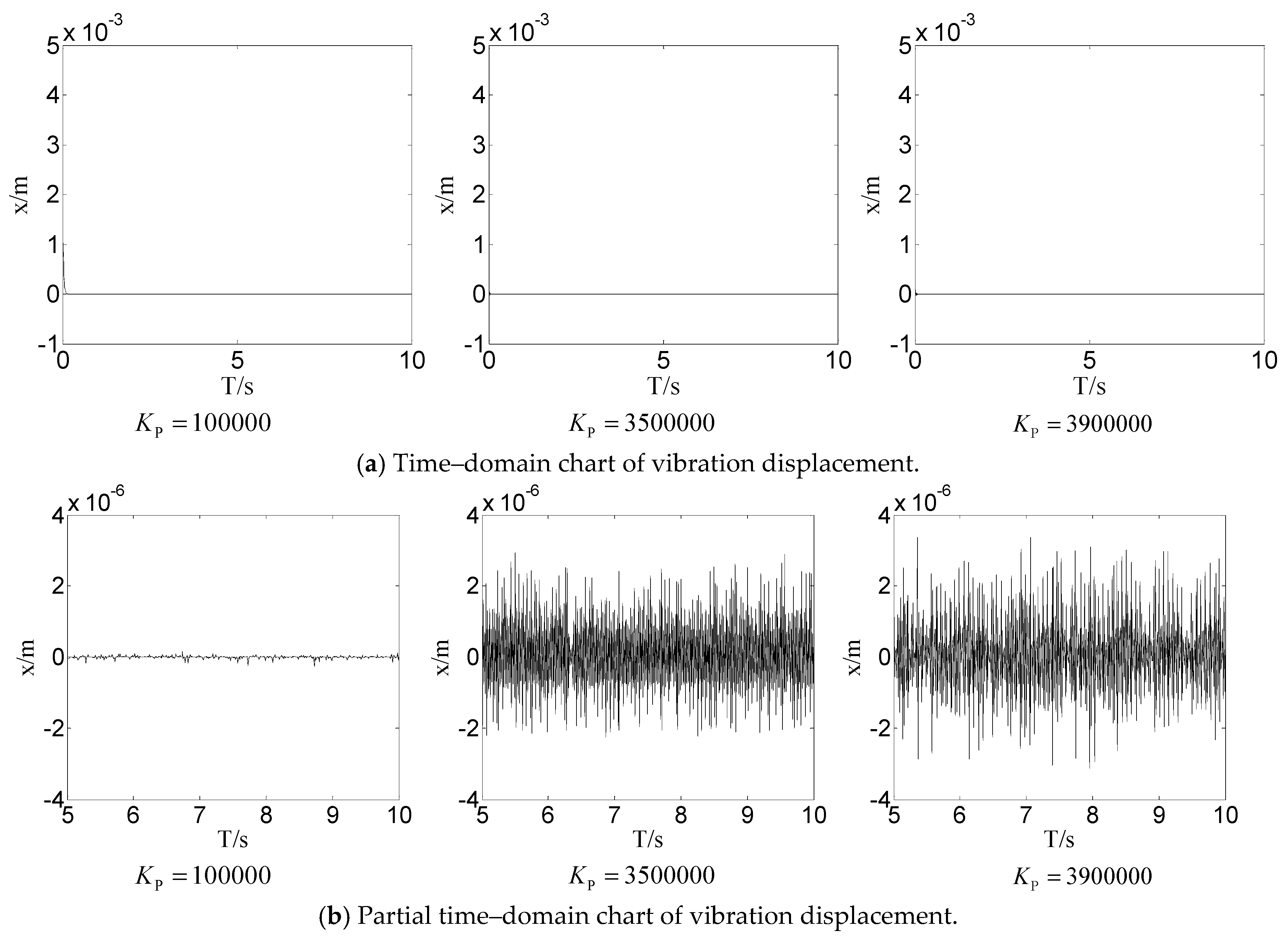
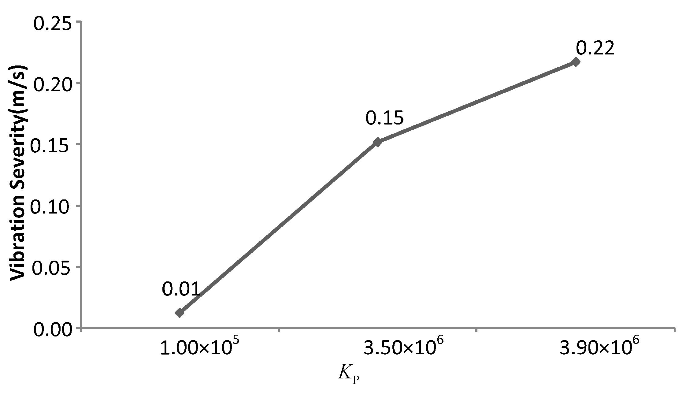
4.2.3. The Influences of Proportional Parameter of Vibration Controller on Nonlinear Dynamic Behavior

The proportional parameters of the controller affect the control effect of vibration suppression. As certain process parameters or structural parameters of the system are changed, fixed parameters K P are bound to have adverse effects. When other parameters are the same, the proportional coefficients of the controller are set as K P = 100,000 , K P = 3,500,000 , and K P = 3,900,000 . Integral coefficient K I = 0.001 , and differential coefficient K D = 0 . The initial value is set as X 00 = [ 0.001 , 0 , 0 ] . The time–domain diagram and the vibration displacement–speed phase diagram of the cylinder are shown in Figure 8. With the proportional coefficient increasing, the vibration intensity of the cylinder is reveled in Figure 9.
The PID control algorithm, with the characteristics of simple structure and convenient implementation, can be well applied to practical engineering. In the PID control algorithm, the proportion coefficient determines the speed of system response, and the appropriate integral coefficient can effectively eliminate the system error. Therefore, increasing the proportional coefficient can improve the response speed of the system, but a big proportional coefficient may cause the system instability.
As shown in Figure 8, the amplitude of the vibration displacement of the cylinder increases significantly with the proportional coefficient of the controller increasing. It can be seen from the phase diagram that the system migrates from the convergence state to the periodic and quasi-periodic states. From the variation of vibration intensity in Figure 9, it can be found that the vibration severity increases with the increase of the proportion coefficient. The results show that reasonable control parameters K P can effectively suppress system vibration. As the process parameters or system’s structural parameters change, the control parameters K P become relatively large, which will increase the vibration and cause the system to become unstable.

5. Conclusions

In this paper, the effects of different equivalent damping coefficients, leakage coefficients in the hydraulic cylinder, and proportional coefficients of the PID controller on the vertical vibration of the rolling mill were studied. The following conclusions are obtained:
(1)
The friction force applied to the cylinder is nonlinear. The equivalent damping coefficient and internal leakage coefficient change with the working state and ambient temperature. The vibration model of the rolling mill is established by considering the influence of nonlinear friction and parameter uncertainty on the system characteristics.
(2)
When the vibration response of the hydraulic cylinder is analyzed by using a different damping coefficient, it is found that the vibration can be suppressed effectively by increasing the damping coefficient.
(3)
The hydraulic system will inevitably bring leakage problems with the aging of the sealing device. Through the analysis of the leakage coefficient, it is found that the vibration attenuation becomes slower and even periodic vibration appears with the increase of the leakage coefficient.
(4)
The controller is an effective mean to ensure accurate position control. Reasonable controller parameters can effectively suppress vibration, but fixed controller parameters will make negative effects on vibration suppression.

Author Contributions

Conceptualization, W.J. and Y.Z. (Yong Zhu); methodology, Y.Z. (Yongshun Zhang); investigation, Y.Z. (Yongshun Zhang); writing—original draft preparation, Y.Z. (Yongshun Zhang); writing—review and editing, Y.Z. (Yong Zhu) and Z.L.

Funding

This research was funded by [the National Natural Science Foundation of China] grant number [No. 51875498, 51805214], [Key Program of Hebei Natural Science Foundation] grant number [No. E2018203339], [China Postdoctoral Science Foundation] grant number [No. 2019M651722], and [Young issues in the special project of basic research of Yanshan University] grant number [No. 15LGB005].

Conflicts of Interest

The authors declare no conflict of interest.

References

  1. Prihod’ko, I.Y.; Krot, P.V.; Solov’yov, K.V.; Parsenyuk, E.A.; Chernov, P.P.; Pimenov, V.A.; Dolmatov, A.P.; Kharin, A.V. Vibration monitoring system and the new methods of chatter early diagnostics for tandem mill control. In Proceedings of the International Conference on Vibration in Rolling Mills, London, UK, 2006; pp. 87–106. [Google Scholar]
  2. Zhu, Y.; Tang, S.; Quan, L.; Jiang, W.; Zhou, L. Extraction method for signal effective component based on extreme-point symmetric mode decomposition and Kullback-Leibler divergence. J. Braz. Soc. Mech. Sci. Eng. 2019, 41, 100. [Google Scholar] [CrossRef]
  3. Zhu, Y.; Tang, S.; Wang, C.; Jiang, W.; Yuan, X.; Lei, Y. Bifurcation characteristic research on the load vertical vibration of a hydraulic automatic gauge control system. Processes 2019, 7, 718. [Google Scholar] [CrossRef]
  4. Zhu, Y.; Tang, S.; Wang, C.; Jiang, W.; Zhao, J.; Li, G. Absolute stability condition derivation for position closed-loop system in hydraulic automatic gauge control. Processes 2019, 7, 766. [Google Scholar]
  5. Yan, X.Q. Machinery-electric-hydraulic Coupling Vibration Control of Hot Continuous Rolling Mills. J. Mech. Eng. 2011, 47, 61–65. [Google Scholar] [CrossRef]
  6. Zhang, W.; Wang, Y.Q.; Gao, Y.J. Modeling and Simulation of Hydraulic Screw-down System in a Strip Mill. Chin. Hydraul. Pneum. 2004, 1, 21–24. [Google Scholar]
  7. Jiang, W.L.; Zhu, Y.; Zhang, Z.; Zhang, S. Nonlinear Vibration Mechanism of Electro-hydraulic Servo System and Its Experimental Verification. J. Mech. Eng. 2015, 51, 175–184. [Google Scholar] [CrossRef]
  8. Zhu, Y.; Qian, P.F.; Tang, S.G.; Jiang, W.L.; Li, W.; Zhao, J.H. Amplitude-frequency Characteristics Analysis for Vertical Vibration of Hydraulic AGC System under Nonlinear Action. AIP Adv. 2019, 9, 035019. [Google Scholar] [CrossRef]
  9. Zhang, J.; Xia, S.; Ye, S.; Xu, B.; Song, W.; Zhu, S.; Xiang, J. Experimental investigation on the noise reduction of an axial piston pump using free-layer damping material treatment. Appl. Acoust. 2018, 139, 1–7. [Google Scholar] [CrossRef]
  10. Ye, S.G.; Zhang, J.H.; Xu, B.; Zhu, S.Q. Theoretical investigation of the contributions of the excitation forces to the vibration of an axial piston pump. Mech. Syst. Signal Proccess. 2019, 129, 201–217. [Google Scholar] [CrossRef]
  11. Wang, C.; Chen, X.X.; Qiu, N.; Zhu, Y.; Shi, W.D. Numerical and experimental study on the pressure fluctuation, vibration, and noise of multistage pump with radial diffuser. J. Braz. Soc. Mech. Sci. Eng. 2018, 40, 481. [Google Scholar] [CrossRef]
  12. He, X.; Jiao, W.; Wang, C.; Cao, W. Influence of surface roughness on the pump performance based on Computational Fluid Dynamics. IEEE Access 2019, 7, 105331–105341. [Google Scholar] [CrossRef]
  13. Wang, C.; Hu, B.; Zhu, Y.; Wang, X.; Luo, C.; Cheng, L. Numerical study on the gas-water two-phase flow in the self-priming process of self-priming centrifugal pump. Processes 2019, 7, 330. [Google Scholar] [CrossRef]
  14. Qian, J.Y.; Gao, Z.X.; Liu, B.Z.; Jin, Z.J. Parametric study on fluid dynamics of pilot-control angle globe valve. ASME J. Fluids Eng. 2018, 114, 111103. [Google Scholar] [CrossRef]
  15. Qian, J.Y.; Chen, M.R.; Liu, X.L.; Jin, Z.J. A numerical investigation of the flow of nanofluids through a micro Tesla valve. J. Zhejiang Univ.-Sci. A 2019, 20, 50–60. [Google Scholar] [CrossRef]
  16. Xuan, B.T.; Nur, H.; Hideki, Y. Modeling of dynamic friction behaviors of hydraulic cylinders. Mechatronics 2012, 22, 65–75. [Google Scholar]
  17. Yanada, H.; Khaing, W.; Endo, H.; Tran, X. Effect of friction model on simulation of hydraulic actuator. Proccess. J. Syst. Control Eng. 2014, 228, 690–698. [Google Scholar]
  18. Liu, B.; Li, P.; Liu, F.; Liu, H.; Jiang, J. Chaotic Prediction Control of Hydraulic Cylinder Nonlinear Stiffness Constrain System. China Mech. Eng. 2017, 28, 559–564. [Google Scholar]
  19. Yang, X.; Tong, C.N.; Yue, G.F.; Meng, J.J. Dynamic model of chatter for cold rolling. J. Iron Steel Res. Int. 2010, 17, 30–34. [Google Scholar] [CrossRef]
  20. Yang, X.; Tong, C.N. Coupling dynamic model and control of chatter in cold rolling. J. Dyn. Syst. Meas. Control 2012, 4, 0141001. [Google Scholar] [CrossRef]
  21. Bar, A.; Bar, O. Types of mid-frequency vibrations appearing during the rolling mill operation. J. Mater. Proccess. Technol. 2005, 162, 461–464. [Google Scholar] [CrossRef]
  22. Alborz, N.; Farhang, K. Vibration instability in a large motion bistable compliant mechanism due to stribeck friction. J. Vib. Acoust. 2018, 140, 061017. [Google Scholar]
  23. Ibrahim, R.A. Friction-induced vibration, chatter, squeal, and chaos-part II: Dynamics and modeling. Appl. Mech. Rev. 1994, 47, 227–253. [Google Scholar] [CrossRef]
  24. Leine, R.I.; Vancampen, D.H.; Kraker, A.D.E. Strick-slip vibrations induced by alternate friction models. Nonlinear Dyn. 1998, 16, 41–54. [Google Scholar] [CrossRef]
  25. Zhao, W.W.; Qiu, S.X.; Feng, C.Z. Study on the stick-slip phenomenon of hydraulic cylinder based on the LuGre friction model. Des. Res. 2017, 12, 88–92. [Google Scholar]
  26. Zhu, Y.; Jiang, W.L.; Hu, H.S.; Kang, H.Z. A Precise Frequency-domain Integral Method of Vibration Acceleration Signal. ICIC Control Express Lett. 2015, 9, 1617–1624. [Google Scholar]
  27. Zhu, Y.; Jiang, W.L.; Kong, X.D.; Zheng, Z.; Hu, H.S. An Accurate Integral Method for Vibration Signal Based on Feature Information Extraction. Shock Vib. 2015, 2015, 962793. [Google Scholar] [CrossRef]
  28. Khan, H.; Seraphin, C.A.; Sepehri, N. Nolinear observer-based fault detection technique for electro-hydraulic servo-positioning systems. Mechatronics 2005, 15, 1040–1041. [Google Scholar] [CrossRef]
  29. Liu, J.X.; Qiao, B.J.; Zhang, X.W. Adaptive vibration control on electrohydraulic shaking table system with an expanded frequency range: Theory analysis and experimental study. Mech. Syst. Signal Process. 2019, 132, 125. [Google Scholar] [CrossRef]
  30. Su, X. Modeling method and control performance of hydraulic AGC system. QinHuangdao 2018, 11, 37–43. [Google Scholar]
  31. Guan, C.; Pan, S.X. Adaptive sliding mode control of electro-hydraulic system with nonlinear unknown parameters. Control Eng. Pract. 2008, 16, 1276. [Google Scholar] [CrossRef]
Figure 1. Structural diagram of rolling mill.
Processes 07 00792 g001
Figure 2. Structural diagram of the vertical vibration of hydraulic screw down system.
Processes 07 00792 g002
Figure 3. Hydraulic principle diagram of hydraulic screw down system.
Processes 07 00792 g003
Figure 4. Effect of equivalent damping on hydraulic cylinder vibration response.
Processes 07 00792 g004aProcesses 07 00792 g004b
Figure 5. Effect of different equivalent damping on vibration severity of hydraulic cylinder.
Processes 07 00792 g005
Figure 6. Effect of leakage coefficient on hydraulic cylinder vibration response.
Processes 07 00792 g006
Figure 7. Effect of leakage coefficient on vibration severity of hydraulic cylinder.
Processes 07 00792 g007
Figure 8. Effect of proportional parameter on hydraulic cylinder vibration response.
Processes 07 00792 g008aProcesses 07 00792 g008b
Figure 9. Effect of proportional parameter on the vibration severity of hydraulic cylinder.
Processes 07 00792 g009
Table 1. Nominal value of main parameters of hydraulic screw down system.
ParametersValueParametersValue
A p 0.19635   m 2 K p 1 0.0125   A / V
c 1 2.25 × 10 6   N s / m k 1 2.5 × 10 9   N / m
m t 1200   kg F L 2 × 10 6   N
C t 5.0 × 10 16   m 3 / s P a p s 1.8 × 10 7   P a
β e 7 × 10 8   P a ρ 850   kg / m 3
C d 0.62 W 0.025   m
K sv 0.01   m / A L 1 0.15   m
L 0.26   m A b 0.030159   m 2
p b 1.0 × 10 6   P a p t 0.0 × 10 5   P a
σ 0 4.4178 × 10 9   N / m σ 1 1 × 10 5   N s / m
σ 2 1 × 10 5   N s / m f c 16,000   N
fs 22,000   N v s 0.1   m / s

