Rotor-Stator Mixers: From Batch to Continuous Mode of Operation—A Review

Abstract
:1. Introduction
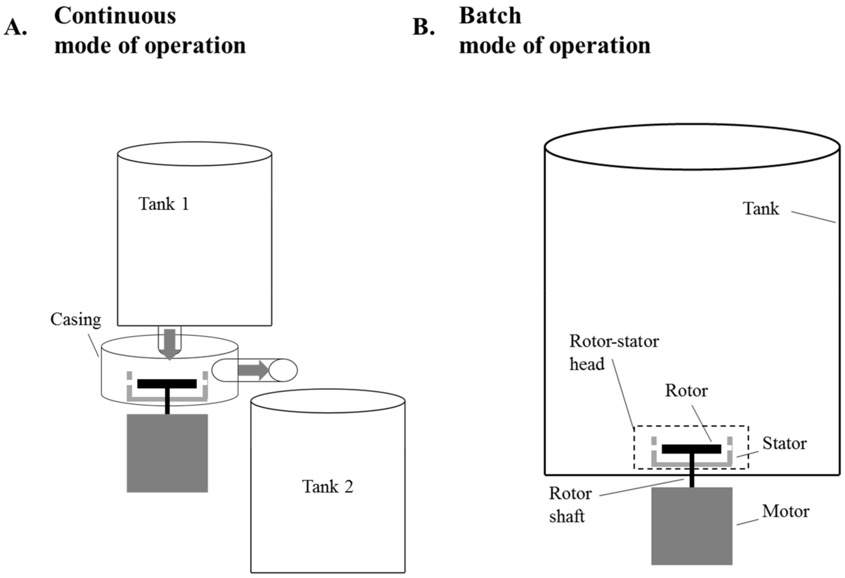
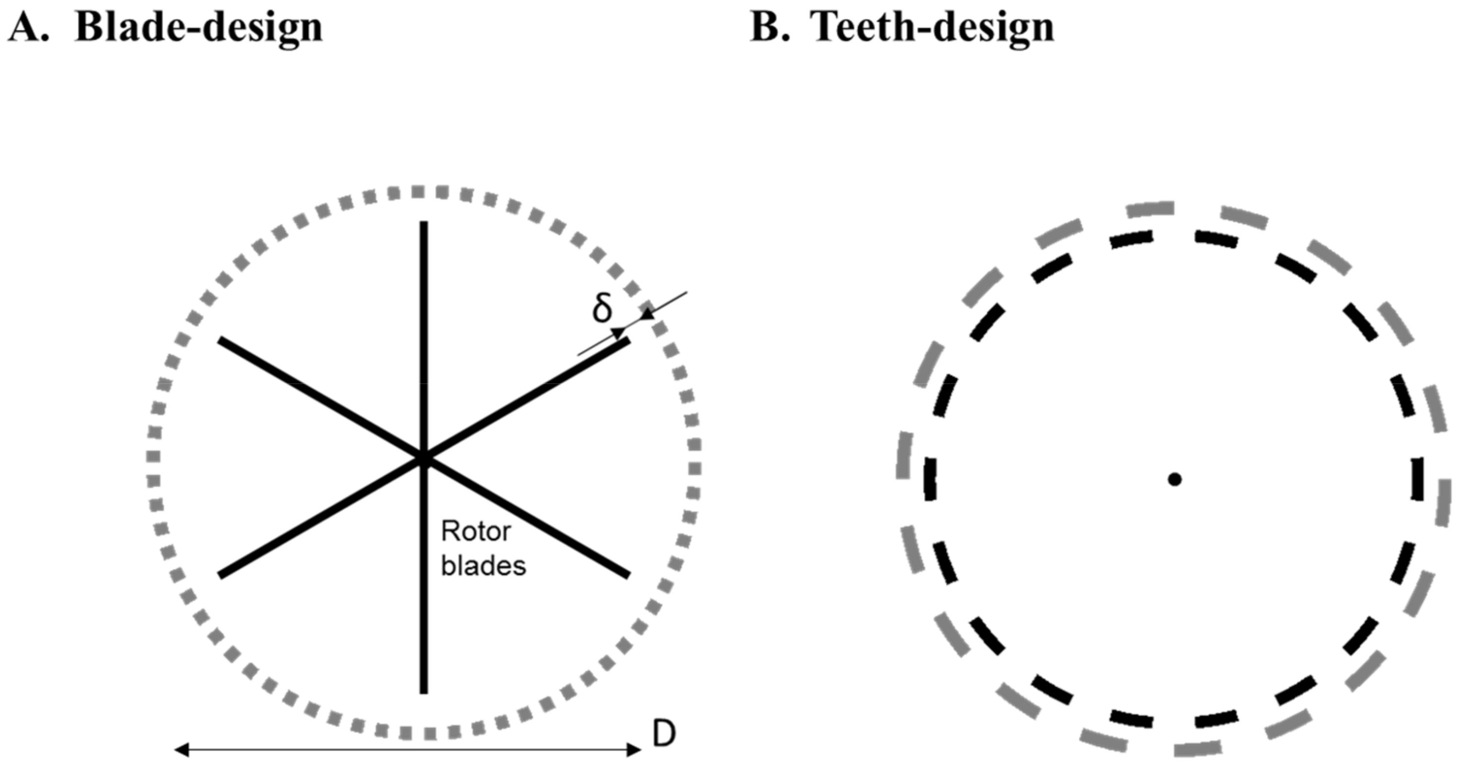
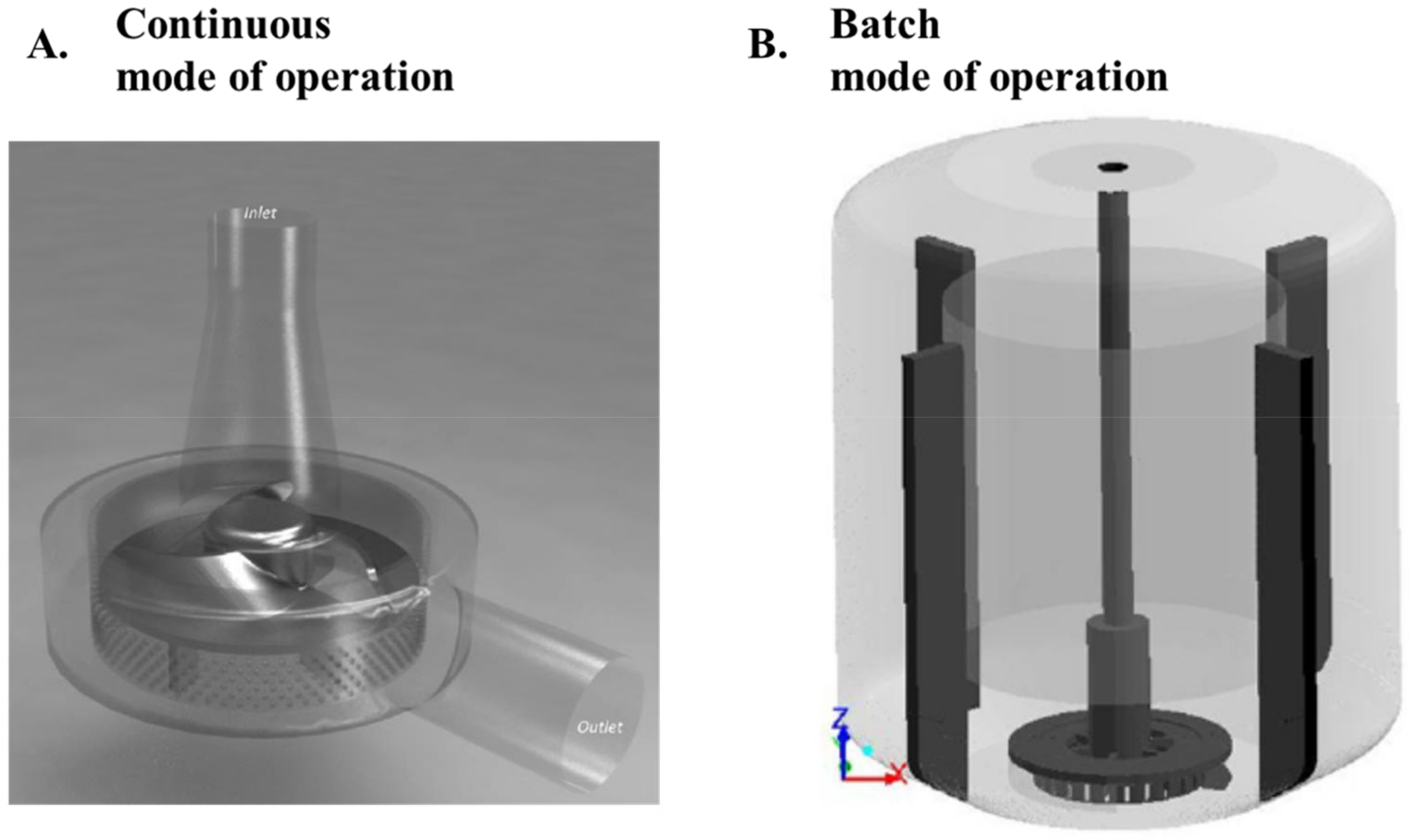
2. The Rotor-Stator Mixer
3. Shaft Power Draw
3.1. Batch Mode RSMs
3.2. Continuous Mode RSMs
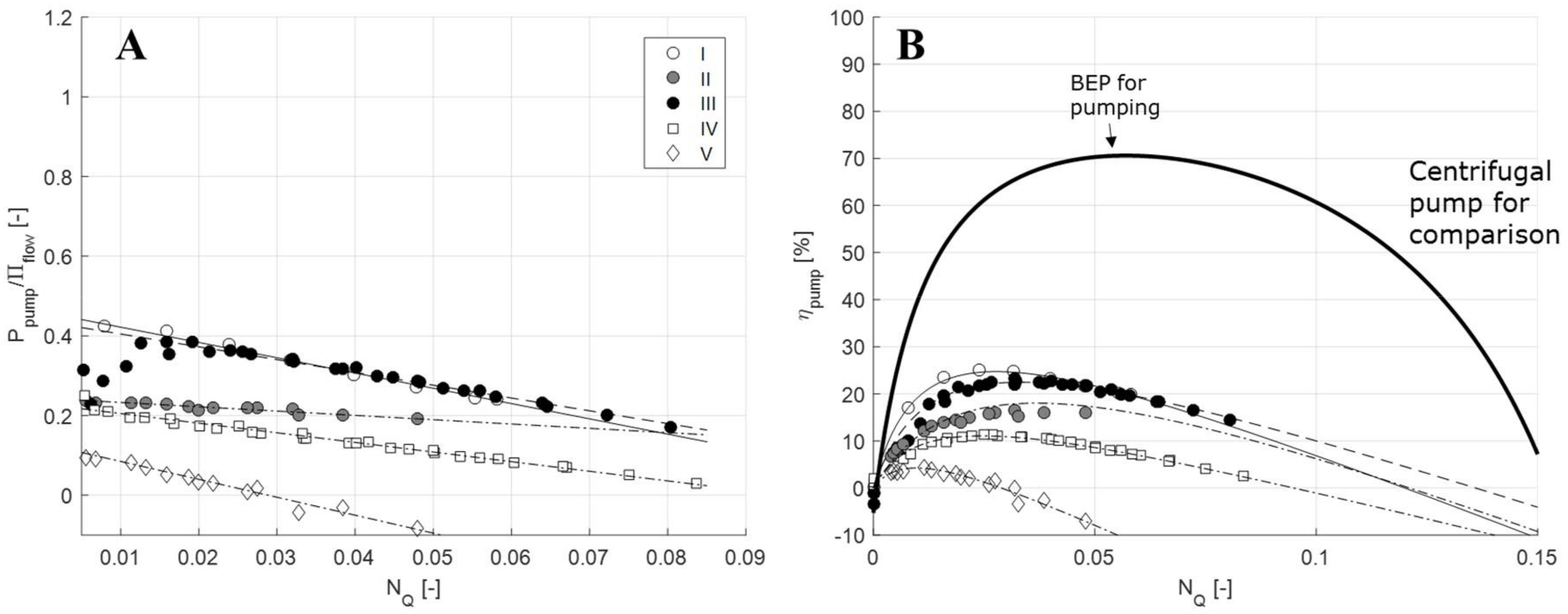
4. RSM Flowrate and Pumping
5. Pumping and Turbulent Dissipation Efficiency
5.1. Batch RSM
5.2. Continuous Mode RSMs
6. Implications for Emulsification
6.1. Flowrate and Its Influence on Turbulence
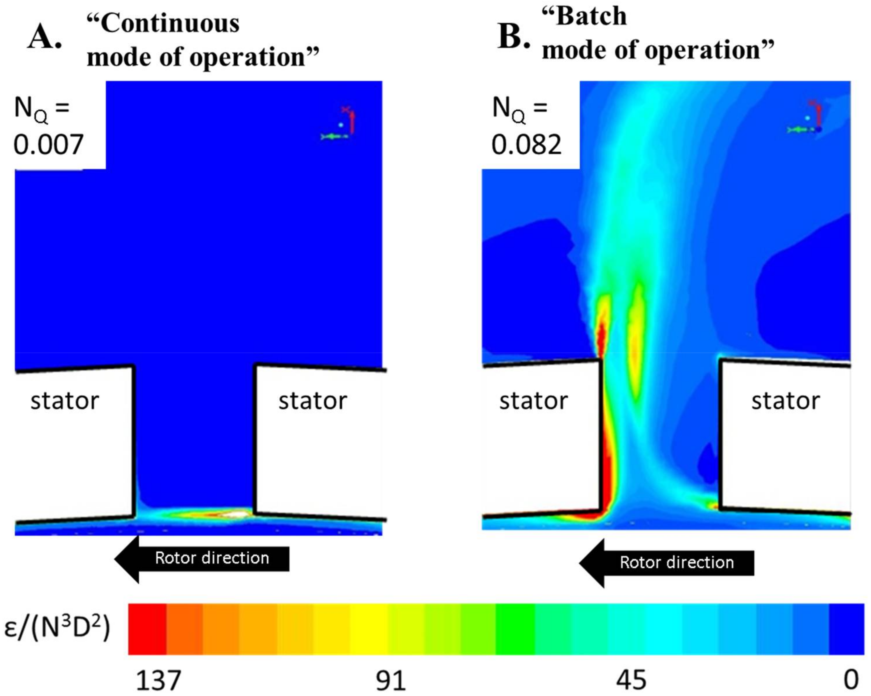
6.2. Radial Flow and Dissiaption Profile Scaling
6.3. A Purely Stochastic Effect
7. Suggestion for Further Research
- Although general models for the scaling of power draw with operating parameters have now been obtained for both modes of operation (Equations (1) and (3)), there is still a lack of systematic investigation into how the model parameters (NP, NP0, NP1) depend on the design parameters (rotor, stator and tank dimensions). A better understanding of this would be helpful in the mechanical design of both batch and continuous mode RSMs.
- As seen throughout this review, the continuous mode RSM could be seen as something between a batch RSM and a centrifugal pump. Further investigations on the relative pumping and turbulence producing properties of different mixer designs (i.e., determination of pumping constants, c1 and c2) would be helpful for choosing the right rotor-stator head for a given application.
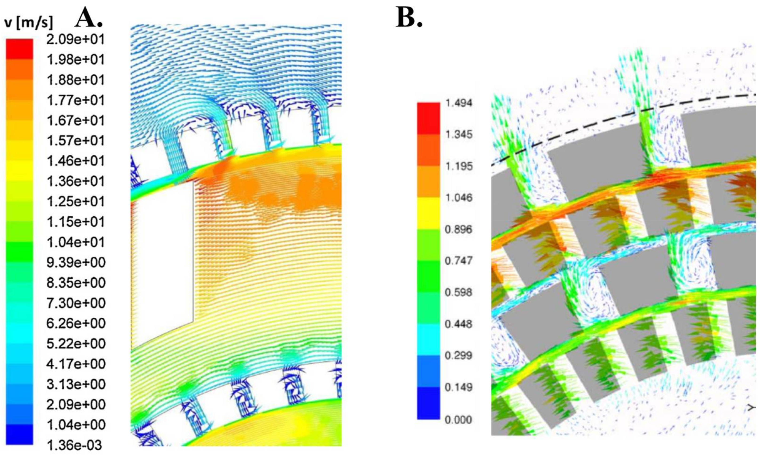
- A large number of experimental studies correlating drop sizes to operating parameters have been published, but it has been difficult to use these studies to obtain a fundamental understanding of the breakup process or the underlying hydrodynamics of RSMs. The single drop breakup visualizations reported by Ashar et al. [42] shows a promising alternative approach where the breakup probabilities are measured directly and then linked to the local hydrodynamic conditions. Expanding these types of investigations into other RSM geometries and repeating it for a continuous mode RSM is needed to further our fundamental understanding.
- As seen in Section 6, there is some remaining uncertainty whether there exist mechanistic differences between breakup when using the same rotor-stator head in the batch or continuous mode of operation. Comparing the scaling suggested by Carrillo De Hert and Rodgers [19] to data from more RSM designs could be one way towards reaching a more definite conclusion; single drop breakup visualization in a continuous mode RSM at varying NQ-values would be another interesting way forward.
8. Summary and Conclusions
Acknowledgments
Conflicts of Interest
References
- Schultz, S.; Wagner, G.; Urban, K.; Ulrich, J. High-pressure homogenization as a process for emulsification. Chem. Eng. Technol. 2004, 27, 361–368. [Google Scholar] [CrossRef]
- Bourne, J.R.; Studer, M. Fast reactions in rotor-stator mixers of different size. Chem. Eng. Process. 1992, 31, 285–296. [Google Scholar] [CrossRef]
- Håkansson, A.; Chaudhry, Z.; Innings, F. Model emulsions to study the mechanism of industrial mayonnaise emulsification. Food Bioprod. Process. 2016, 98, 189–195. [Google Scholar] [CrossRef]
- Calabrese, R. Research needs and opportunities in fluid mixing technology. Chem. Eng. Res. Des. 2001, 79, 111–112. [Google Scholar] [CrossRef]
- Atiemo-Obeng, V.A.; Calabrese, R. Rotor-stator mixing devices. In Handbook of Industrial Mixing; Paul, E.L., Atiemo-Obeng, V.A., Kresta, S.M., Eds.; Wiley: Hoboken, NJ, USA, 2004; pp. 479–505. [Google Scholar]
- Atiemo-Obeng, V.A.; Calabrese, R. Rotor-stator mixing devices. In Advances in Industrial Mixing; Kresta, S.M., Etchells, A.W., Dickey, D.S., Atiemo-Obeng, V.A., Eds.; Wiley: Hoboken, NJ, USA, 2016; pp. 255–258. [Google Scholar]
- Zhang, J.; Xu, S.; Li, W. High shear mixers: A review of typical applications and studies on power draw, slot pattern, energy dissipation and transfer properties. Chem. Eng. Process. 2012, 57–58, 25–41. [Google Scholar] [CrossRef]
- Mortensen, H.H.; Calabrese, R.V.; Innings, F.; Rosendahl, L. Characteristics of a batch rotor-stator mixer performance elucidated by shaft torque and angle resolved PIV measurements. Can. J. Chem. Eng. 2011, 89, 1076–1095. [Google Scholar] [CrossRef]
- Mortensen, H.H.; Innings, F.; Håkansson, A. The effect of stator design on flowrate and velocity fields in a rotor-stator mixer—An experimental investigation. Chem. Eng. Res. Des. 2017, 121, 245–254. [Google Scholar] [CrossRef]
- Mortensen, H.H.; Innings, F.; Håkansson, A. Local levels of dissipation rate of turbulent kinetic energy in a rotor-stator mixer with different stator slot widths—An experimental investigation. Chem. Eng. Res. Des. 2018, 130, 52–62. [Google Scholar] [CrossRef]
- Xu, S.; Cheng, Q.; Li, W.; Zhang, J. LDA Measurements and CFD simulations of an in-line high shear mixer with ultrafine teeth. AIChE J. 2014, 60, 1143–1155. [Google Scholar] [CrossRef]
- Utomo, A.; Baker, M.; Pacek, A.W. Flow pattern, periodicity and energy dissipation in a batch rotor-stator mixer. Chem. Eng. Res. Des. 2008, 89, 1397–1409. [Google Scholar] [CrossRef]
- Håkansson, A.; Mortensen, H.H.; Andersson, R.; Innings, F. Experimental investigations of turbulent fragmenting stresses in a Rotor-Stator Mixer. Part 1. Estimation of turbulent stresses and comparison to breakup visualizations. Chem. Eng. Sci. 2017, 171, 625–637. [Google Scholar] [CrossRef]
- Jasinska, M.; Baldyga, J.; Hall, S.; Pacek, A.W. Dispersion of oil droplets in rotor-stator mixers: Experimental investigations and modelling. Chem. Eng. Process. 2014, 84, 45–53. [Google Scholar] [CrossRef]
- Özcan-Taskin, G.; Kubicki, D.; Padron, G. Power and flow characteristics of three rotor-stator heads. Can. J. Chem. Eng. 2011, 89, 1005–1017. [Google Scholar] [CrossRef]
- Jasinska, M.; Baldyga, J.; Cooke, M.; Kowalski, A.J. Specific features of power characteristics of in-line rotor-stator mixers. Chem. Eng. Process. 2015, 9, 143–159. [Google Scholar] [CrossRef]
- Utomo, A.; Baker, M.; Pacek, A.W. The effect of stator geometry on the flow pattern and energy dissipation rate in a rotor-stator mixer. Chem. Eng. Res. Des. 2009, 87, 533–542. [Google Scholar] [CrossRef]
- Espinoza, C.J.U.; Simmons, M.J.H.; Albertini, F.; Mihailova, O.; Rothman, D.; Kowalski, A.J. Flow studies in an in-line Silverson 150/250 high shear mixer using PIV. Chem. Eng. Res. Des. 2018, 132, 989–1004. [Google Scholar] [CrossRef]
- Carrillo De Hert, S.; Rodgers, T.L. Continuous, recycle and batch emulsification kinetics using a high-shear mixer. Chem. Eng. Sci. 2017, 167, 265–277. [Google Scholar] [CrossRef]
- Unwin, W.C. On the friction of water against solid surfaces of different degrees of roughness. Proc. R. Soc. Lond. 1880, 31, 54–58. [Google Scholar] [CrossRef]
- White, A.M.; Brenner, E. Studies in agitation vs. the correlation of power data. Trans. Am. Inst. Chem. Eng. 1934, 30, 555–597. [Google Scholar]
- Rushton, J.H.; Costich, E.W.; Everett, H.J. Power characteristics of mixing impellers. Part 1. Chem. Eng. Prog. 1950, 46, 395–404. [Google Scholar]
- Bates, R.L.; Fondy, P.L.; Corpstein, R.R. An examination of some geometric parameters of impeller power. Ind. Eng. Chem. Process Des. Dev. 1963, 2, 310–314. [Google Scholar] [CrossRef]
- Padron, G.A. Measurement and Comparison of Power Draw in Batch Rotor-Stator Mixers. Master’s Thesis, University of Maryland, College Park, MD, USA, 2001. [Google Scholar]
- Myers, K.J.; Reeder, M.F.; Ryan, D. Power draw of a high-shear homogenizer. Can. J. Chem. Eng. 2001, 79, 94–99. [Google Scholar] [CrossRef]
- James, J.; Cooke, M.; Trinh, L.; Hou, R.; Martin, P.; Kowalski, A.; Rodgers, T.L. Scale-up of batch rotor-stator mixers. Part 1–Power constants. Chem. Eng. Res. Des. 2017, 124, 313–320. [Google Scholar] [CrossRef]
- Cheng, Q.; Xu, S.; Shi, J.; Li, W.; Zhang, J. Pump capacity and power consumption of two commercial in-line high shear mixers. Ind. Eng. Chem. Res. 2012, 52, 525–537. [Google Scholar] [CrossRef]
- Cooke, M.; Rodgers, T.L.; Kowalski, A.J. Power consumption characteristics of an in-line Silverson high shear mixer. AIChE J. 2012, 58, 1683–1692. [Google Scholar] [CrossRef]
- Nienow, A.W. On impeller circulation and mixing effectiveness in the turbulent flow regime. Chem. Eng. Sci. 1997, 52, 2257–2565. [Google Scholar] [CrossRef]
- Baldyga, J.A.; Kowalski, A.J.; Cooke, M.; Jasinska, M. Investigations of micromixing in the rotor-stator mixer. Chem. Process Eng. 2007, 28, 867–877. [Google Scholar]
- Hall, S.; Pacek, A.W.; Kowalski, A.J.; Cooke, M.; Rothman, D. The effect of scale and interfacial tension on liquid–liquid dispersion in-line Silverson rotor-stator mixers. Chem. Eng. Res. Des. 2013, 91, 2156–2168. [Google Scholar]
- Kowalski, A.J. Power consumption of in-line rotor-stator devices. Chem. Eng. Process. 2009, 48, 581–585. [Google Scholar] [CrossRef]
- Kowalski, A.J.; Cooke, M.; Hall, S. Expression for turbulent power draw of an inline Silverson high shear mixer. Chem. Eng. Sci. 2011, 66, 241–249. [Google Scholar] [CrossRef]
- Sparks, T. Fluid Mixing in Rotor/Stator Mixers. Ph.D. Thesis, Cranfield University, Cranfield, UK, 1996. [Google Scholar]
- Håkansson, A.; Innings, F. The dissipation rate of turbulent kinetic energy and its relation to pumping power in inline rotor-stator mixers. Chem. Eng. Process. 2017, 115, 46–55. [Google Scholar] [CrossRef]
- Lindahl, A. Fluid Dynamics of Rotor Stator Mixers. Master’s Thesis, Luleå University, Luleå, Sweden, 2013. [Google Scholar]
- Schönstedt, B.; Jacob, H.-J.; Schilde, C.; Kwade, A. Scale-up of the power draw of inline-rotor-stator mixers with high throughput. Chem. Eng. Res. Des. 2015, 93, 12–20. [Google Scholar] [CrossRef]
- Pacek, A.; Baker, M.; Utomo, A.T. Characterisation of flow pattern in a rotor stator high shear mixer. In Proceedings of the European Congress of Chemical Engineering, Copenhagen, Denmark, 16–20 September 2007. [Google Scholar]
- Hall, S.; Cooke, M.; Pacek, A.W.; Kowalski, A.J.; Rothman, D. Scaling up of silverson rotor-stator mixers. Can. J. Chem. Eng. 2011, 89, 1040–1050. [Google Scholar] [CrossRef]
- Jasinska, M.; Baldyga, J.; Cooke, M.; Kowalski, A. Application of test reactions to study micromixing in the rotor-stator mixer (test reactions for rotor-stator mixer). Appl. Therm. Eng. 2013, 57, 172–179. [Google Scholar] [CrossRef]
- Rueger, P.E.; Calabrese, R.V. Dispersion of water into oil in a rotor-stator mixer. Part 1: Drop breakup in dilute systems. Chem. Eng. Res. Des. 2013, 91, 2122–2133. [Google Scholar] [CrossRef]
- Ashar, M.; Arlov, D.; Carlsson, F.; Innings, F.; Andersson, R. Single droplet breakup in a rotor-stator mixer. Chem. Eng. Sci. 2018, 181, 186–198. [Google Scholar] [CrossRef]
- White, F. Fluid Mechanics, 4th ed.; McGraw-Hill: Boston, MA, USA, 1998; ISBN 0070697167. [Google Scholar]
- Kolmogorov, A.N. On the breakage of drops in a turbulent flow. Dokl. Akad. Nauk. SSSR 1949, 66, 825–828. [Google Scholar]
- Hinze, J.O. Fundamentals of the Hydrodynamic Mechanism of Splitting in dispersion processing. AIChE J. 1955, 1, 289–295. [Google Scholar] [CrossRef]
- Davies, J.T. Drop sizes of emulsions related to turbulent energy dissipation rates. Chem. Eng. Sci. 1985, 40, 839–842. [Google Scholar] [CrossRef]
- Vankova, N.; Tcholakova, S.; Denkov, N.D.; Ivanov, I.B.; Vulchev, V.D.; Danner, T. Emulsification in turbulent flow 1. Mean and maximum drop diameters in inertial and viscous regimes. J. Colloid Interface Sci. 2007, 312, 363–380. [Google Scholar] [CrossRef] [PubMed]
- Walstra, P. Emulsions. In Fundamentals of Interface and Colloid Science; Lyklema, J., Ed.; Elsevier: Amsterdam, The Netherland, 2005; Volume 5, pp. 1–94. ISBN 9780124605305. [Google Scholar]
- Zhou, G.; Kresta, S.M. Correlation of mean drop size and minimum drop size with the turbulence energy dissipation and the flow in an agitated tank. Chem. Eng. Sci. 1998, 53, 2063–2079. [Google Scholar] [CrossRef]
- Håkansson, A.; Fuchs, L.; Innings, F.; Revstedt, J.; Trägårdh, C.; Bergenståhl, B. High resolution experimental measurement of turbulent flow field in a high pressure homogenizer model and its implications on turbulent drop fragmentation. Chem. Eng. Sci. 2011, 66, 1790–1801. [Google Scholar] [CrossRef]
- Hall, S.; Cooke, M.; El-Hamouz, A.; Kowalski, A.J. Droplet break-up by in-line Silverson rotor-stator mixer. Chem. Eng. Sci. 2011, 66, 2068–2079. [Google Scholar] [CrossRef]
- Karbstein, H.; Schubert, H. Developments in the continuous mechanical production of oil-in-water macro-emulsions. Chem. Eng. Process. 1995, 34, 205–211. [Google Scholar] [CrossRef]
- Rodgers, T.L.; Cooke, M. Rotor-stator devices: The role of shear and the stator. Chem. Eng. Res. Des. 2012, 90, 323–327. [Google Scholar] [CrossRef]
- Håkansson, A.; Arlov, D.; Carlsson, F.; Innings, F. Hydrodynamic difference between inline and batch operation of a rotor-stator mixer head—A CFD approach. Can. J. Chem. Eng. 2017, 95, 806–816. [Google Scholar] [CrossRef]
- Mortensen, H.H.; Arlov, D.; Innings, F.; Håkansson, A. A validation of commonly used CFD methods applied to Rotor Stator Mixers using PIV measurements of fluid velocity and turbulence. Chem. Eng. Sci. 2018, 177, 340–353. [Google Scholar] [CrossRef]


| RSM | Power Characteristics | Pumping Characteristics * | Ref. | Figure 5 ** | |||||
|---|---|---|---|---|---|---|---|---|---|
| Rotor | Stator | Manufacturer | D (m) | NP0 | NP1 | c1 | c2 | ||
| Blade | Circular holes | Tetra Pak | 0.20 | 0.11 | 9.2 | 0.46 | −3.8 | [36] | I |
| Blade | Square holes | Fluko | 0.060 | 0.24 | 8.4 | 0.24 | −1.1 | [27] | II |
| Blade | Circular holes | Silverson | 0.12 | 0.10 | 6.4 | 0.44 | −3.2 | [34] | III |
| Teeth (1 row) | Teeth | Ystral | 0.12 | 0.13 | 9.7 | 0.23 | −2.4 | [34] | IV |
| Teeth (2 rows) | Teeth | Fluko | 0.060 | 0.15 | 14.5 | 0.13 | −4.5 | [27] | V |
| RSM | Rotor Speed, U (m/s) | NQ (-) | Method * | Ref. | |||
|---|---|---|---|---|---|---|---|
| Rotor | Stator | Manufacturer | D (m) | ||||
| Batch Mode of Operation | |||||||
| Blade | Rectangular slots | Tetra Pak | 0.20 | 3–14 | 0.11 | PIV | [8] |
| Blade | Rectangular slots | Tetra Pak | 0.20 | 3–14 | 0.11–0.15 | PIV | [9] |
| Blade | Circular holes | Silverson | 0.0028 | 3–5 | 0.22 | LDA | [12,38] |
| Blade | Rectangular slots | Silverson | 0.0028 | 6 | 0.18 | CFD | [17] |
| Blade | Square holes | Silverson | 0.0028 | 6 | 0.26 | CFD | [17] |
| Inline Mode of Operation | |||||||
| Blade | Circular holes | Tetra Pak | 0.20 | 20 | 0.02–0.06 | - | [3] |
| Blade | Circular holes | Silverson | 0.040 | 6–22 | 0.0003–0.037 | - | [39] |
| Blade | Circular holes | Silverson | 0.022 | 5–12 | 0.0003–0.0095 | - | [39] |
| Blade | Circular holes | Silverson | 0.0038 | 6–10 | 0.002–0.04 | - | [16] |
| Blade | Circular holes | Silverson | 0.12 | 13–19 | 0.0005–0.08 | - | [34] |
| Teeth | Teeth | Ystral | 0.12 | 13–19 | 0.0005–0.08 | - | [34] |
| Teeth | Teeth | Fluko | 0.060 | 5–10 | <0.05 | - | [27] |
| Blade | Circular holes | Fluko | 0.060 | 5–10 | <0.05 | - | [27] |
© 2018 by the author. Licensee MDPI, Basel, Switzerland. This article is an open access article distributed under the terms and conditions of the Creative Commons Attribution (CC BY) license (http://creativecommons.org/licenses/by/4.0/).
Share and Cite
Håkansson, A. Rotor-Stator Mixers: From Batch to Continuous Mode of Operation—A Review. Processes 2018, 6, 32. https://doi.org/10.3390/pr6040032
Håkansson A. Rotor-Stator Mixers: From Batch to Continuous Mode of Operation—A Review. Processes. 2018; 6(4):32. https://doi.org/10.3390/pr6040032
Chicago/Turabian StyleHåkansson, Andreas. 2018. "Rotor-Stator Mixers: From Batch to Continuous Mode of Operation—A Review" Processes 6, no. 4: 32. https://doi.org/10.3390/pr6040032
APA StyleHåkansson, A. (2018). Rotor-Stator Mixers: From Batch to Continuous Mode of Operation—A Review. Processes, 6(4), 32. https://doi.org/10.3390/pr6040032