Integrated Design and Performance Validation of an Advanced VOC and Paint Mist Recovery System for Shipbuilding Robotic Spraying
Abstract
1. Introduction
2. Design of VOCs and Paint Mist Recovery System for Ship Automatic-Spraying Robots
2.1. Design Requirements Specification
- (1)
- Mandatory Requirements from Environmental Standards
- Paint mist recovery efficiency ≥ 90%, with outlet paint mist concentration ≤ 1 mg/m3;
- VOC removal efficiency ≥ 80%, with outlet VOC concentration ≤ 10 mg/m3;
- The system shall not cause secondary pollution during operation, and the filter material shall meet the hazardous waste disposal specifications of the shipbuilding industry.
- (2)
- Compatibility Requirements for Automatic-Spraying Robots
- Load limit: The total weight of the recovery system shall not exceed 35 kg, to avoid exceeding the robot’s end load rating;
- Installation space: The overall volume of the system shall be ≤0.3 m3, and the modular installation structure shall be compatible with the reserved mounting holes in the robot’s body;
- Trajectory adaptability: The recovery hood and air curtain device shall not block the spray gun’s working range, and shall adapt to the robot’s moving speed of 0.4–0.6 m/s and spraying angle of 0–90.
- (3)
- Environmental Adaptability Requirements for Shipyard Working Conditions
- Humidity adaptability: The system and filter materials shall maintain stable performance in an environment with a relative humidity of 40–80%, without moisture absorption blockage or performance degradation;
- Continuous operation: The system shall maintain stable recovery efficiency after 8 h of continuous operation, to meet the daily working hours of the shipyard;
- Corrosion resistance: The main body of the recovery box shall be resistant to corrosion by paint organic solvents, to adapt to the long-term exposure to a VOC atmosphere.
- (4)
- Purification Performance Requirements Based on Pollutant Characteristics
- Paint mist treatment: The filter material shall achieve graded interception of paint mist particles with a particle size of 1–10 μm (accounting for 90% of the total paint mist), especially for the secondary rebound paint mist with particle size < 5 μm;
- VOCs treatment: The adsorption material shall have rapid adsorption capacity for the benzene series (benzene, toluene, and xylene), which accounts for 50–60% of the total VOCs in ship painting, to adapt to the high airflow and short contact time of the mobile recovery system.
- (5)
- Engineering Maintainability and Economic Requirements
- The filter and adsorption materials shall adopt a drawer-type replaceable structure, and the single replacement time shall not exceed 10 min;
- The adsorption material shall have regenerable performance, and the adsorption capacity shall remain above 85% after at least five regeneration cycles, to reduce the operation cost;
- The annual material consumption cost of a single set of the system shall be ≤5000 RMB, to meet the cost control requirements of the shipyard.
2.2. Composition of the VOCs and Paint Mist Recovery Collaborative System
- (1)
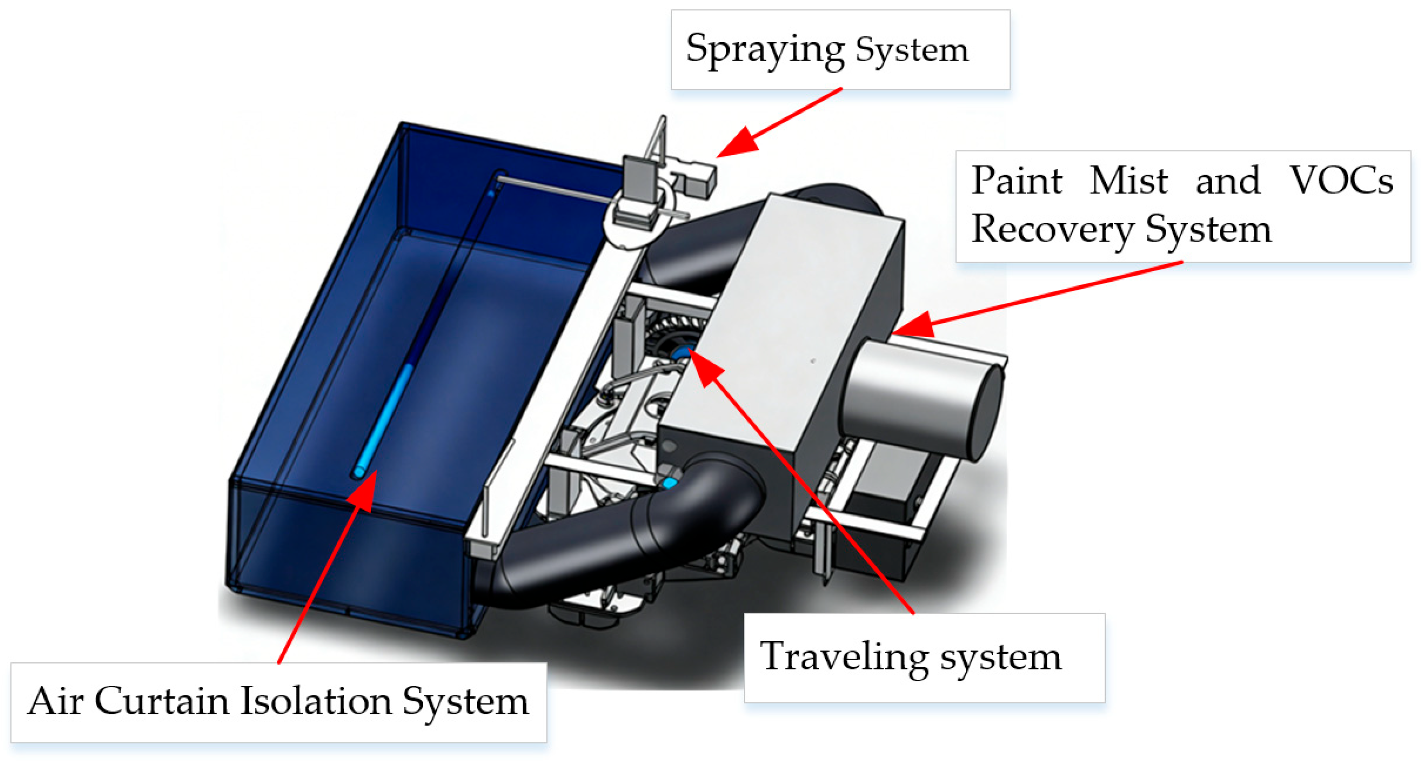
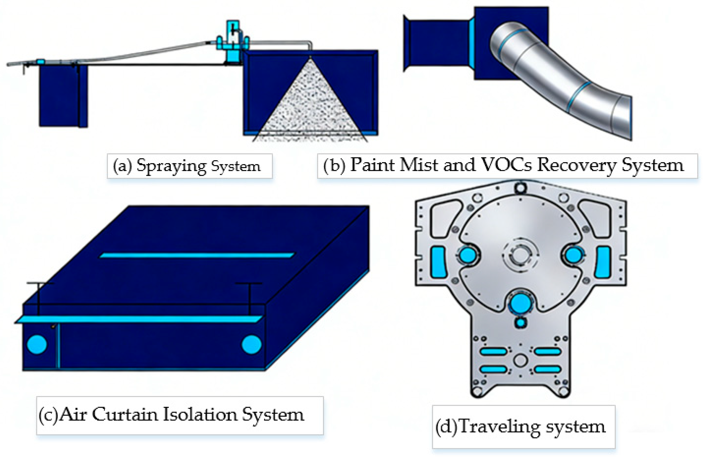
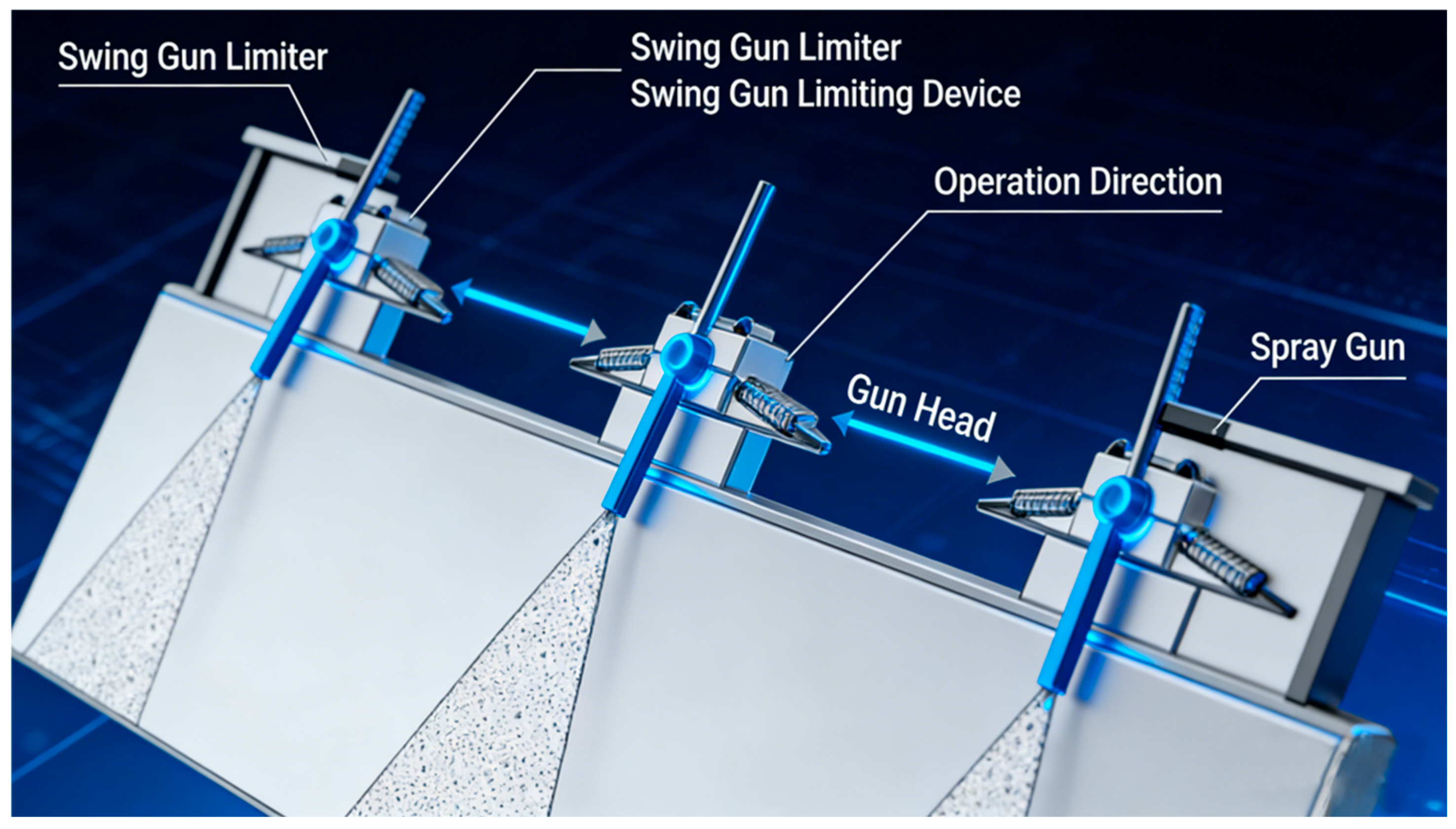
- Spraying system: This system adopts a high-pressure electrostatic spraying scheme, and its core process design follows the mature industrial electrostatic spraying application framework verified in existing engineering research [17]. The system is equipped with a high-pressure electrostatic spray gun that operates at a spraying pressure of 0.3–0.5 MPa and delivers a spray width of 200–300 mm, which atomizes the paint and ensures its adhesion to the ship’s surface. Guided by the automatic control system, the spray gun adjusts its moving speed within 0.4–0.6 m/s and maintains a working distance of 250–350 mm from the workpiece according to the curvature of the ship plate, achieving a 15% reduction in over-spraying compared with manual spraying.Guided by the automatic control system, the spray gun adjusts its moving speed within 0.4–0.6 m/s and maintains a working distance of 250–350 mm from the workpiece according to the curvature of the ship plate, achieving a 15% reduction in over-spraying compared with manual spraying. This optimization effect is consistent with the law verified in existing research: the matching of spraying motion parameters and gun parameters can significantly improve the transfer efficiency of electrostatic spraying and reduce the generation of over-sprayed paint mist [18].
- (2)
- Air curtain isolation system: As the core component to prevent pollutant diffusion for mobile spraying robots, the system draws on the structural optimization experience of air-assisted anti-diffusion for mobile spraying equipment [19] and adopts perforated air pipes with an aperture of 2 mm and a hole spacing of 5 mm arranged along the edge of the recovery hood. Compressed air with a pressure of 0.3–0.5 MPa is injected through the pipes to form a 5–8 cm-thick vertical air curtain, which can block 95% of paint mist and VOCs from escaping. The key parameters of the air curtain are optimized to balance diffusion prevention and spraying airflow stability.
- (3)
- VOCs and paint mist recovery system: As the core module for pollution control, this system is responsible for the collection and purification of pollutants, and its detailed composition is elaborated in Section 2.3.
- (4)
- Traveling system: This system adopts a magnetic adsorption wall-climbing structure with an adsorption force of no less than 150 N, which can adapt well to the vertical and overhead surfaces of the ship hull. It ensures that the recovery hood maintains a working distance of 10–15 mm from the workpiece, a range verified as the optimal interval for paint mist collection [20].
- (5)
- Automatic control system: The system adopts a modular PLC control architecture with a SIMATIC S7-1200 controller (Siemens AG, Munich, Germany) as the core, equipped with laser ranging sensors, differential pressure sensors, and VOC concentration detectors as the feedback terminals. The core control logic includes two parts:
- Synchronous linkage control, which realizes real-time matching of robot traveling speed, spraying pressure, air curtain flow rate, and axial fan speed;
- Adaptive adjustment control, which automatically increases the air curtain flow by 10–20% and fan negative pressure by 15% when the robot moves to curved surfaces, or vertical or overhead spraying positions, to compensate for pollutant diffusion risks. The system supports both automatic cyclic operation and manual parameter adjustment, with a response delay of less than 200 ms to ensure stable coordination of all subsystems under dynamic working conditions.
- Field layer: the on-board PLC of each equipment executes independent real-time control and data collection;
- Central control layer: the upper industrial computer realizes unified parameter setting and operation scheduling of multiple equipment via industrial Ethernet;
- Monitoring layer: the host computer platform realizes batch status monitoring, emission data management, and maintenance reminders for all equipment.
- (6)
- Scalability Requirements for Vessel Sizes and Spray Booth Configurations
- Vessel size adaptability: The core system architecture remains unchanged when adjusting key modules to match different vessel dimensions. For small- and medium-sized vessels (≤5000 tons), the system can be configured with a compact recovery hood (width 400–600 mm), single-stage filter module, and low-power fan; for large vessels (10,000–30,000 tons) and ultra-large vessels (≥30,000 tons), it supports parallel expansion of 2–4 sets of filter-adsorption modules, enlarged recovery hood (width 800–1200 mm), and high-power fan to adapt to large-area and long-stroke spraying of large hulls.
- Spray booth configuration adaptability: The system supports flexible reconfiguration according to different spray booth layouts (open-air spraying workshop, closed fixed-spray booth, and narrow cabin spraying space). For closed spray booths with fixed ventilation systems, the system’s exhaust module can be directly connected to the workshop’s central air duct; for narrow cabin spraying, it can be equipped with a miniaturized split-type recovery module and flexible air duct while retaining full purification functions.
- Project-specific demand adaptability: All functional modules adopt standardized electrical and mechanical interfaces, supporting rapid reconfiguration without changing the core control logic. For projects with strict emission requirements, an additional deep VOC adsorption module can be added; for high-frequency continuous operation projects, a double-filter alternate working module can be configured to meet the specific needs of different shipbuilding projects.
- Batch application adaptability: All core components adopt a standardized design to support batch manufacturing, assembly, and independent deployment on multiple spraying robots for large-scale ship-painting projects.
- Cross-industry adaptability: The core system architecture remains universal, supporting flexible parameter adjustment and modular reconstruction to adapt to automated spraying scenarios in other industries (e.g., automotive, steel structure, and engineering machinery).
- Material saturation warning: when the pressure difference across the filter-adsorption layer exceeds 300 Pa, the system sends a material replacement reminder;
- Airflow abnormality warning: when the negative pressure in the recovery hood deviates from the set range of −50~−80 Pa for more than 3 s, the system automatically adjusts the fan speed and sends an equipment fault warning;
- Over-limit emission warning: when the outlet VOC concentration exceeds 10 mg/m3, the system triggers an audible and visual alarm and stops the spraying operation synchronously to avoid excessive pollutant emission.
- (7)
- Scalability Requirements:
- Dimensional adaptability: The core system architecture shall remain unchanged when adjusting the recovery hood size, filter module capacity, and fan power to match different robot models and hull-spraying scenarios.
- Batch application adaptability: All core components shall adopt a standardized design to support batch manufacturing, assembly, and independent deployment on multiple spraying robots for large-scale ship-painting projects.
- Cross-industry adaptability: The core system architecture shall remain universal, supporting flexible parameter adjustment and modular reconstruction to adapt to automated spraying scenarios in other industries (e.g., automotive, steel structure, and engineering machinery).
2.3. Detailed Design of the VOC and Paint Mist Recovery System
2.3.1. Selection of Adsorption and Filtration Materials
- (1)
- Targeted purification matching the pollutant characteristics of ship painting;
- (2)
- Environmental adaptability to shipyard harsh working conditions;
- (3)
- Stable operation matching the system airflow and load constraints;
- (4)
- Long service life and economic feasibility for engineering applications.
Selection Criteria for Glass Fiber Filter Cotton (Paint Mist Interception Layer)
- (1)
- Paint mist interception efficiency criterion: The total paint mist interception rate must be ≥90%, with ≥80% interception efficiency for large particles (>5 μm) and ≥95% for fine particles (1–5 μm), to meet the national standard requirement of paint mist recovery rate ≥ 90%.
- (2)
- Environmental adaptability criterion: High-temperature resistance ≥ 200 °C, with no moisture absorption, blockage, or strength attenuation under long-term high-humidity conditions, to adapt to the volatile and humid shipyard spraying environment.
- (3)
- Dust-holding and service life criterion: Dust-holding capacity ≥ 3 kg/m2, to meet 7 days of continuous operation under the ship’s daily spraying volume (8–12 L) without frequent replacement.
- (4)
- System compatibility criterion: Filtration resistance ≤ 100 Pa, matching the static pressure of the matched axial flow fan, avoiding excessive airflow resistance that affects the negative pressure collection effect of the mobile system.
Selection Criteria for Activated Carbon Fiber (VOC Adsorption Layer)
- (1)
- Targeted adsorption performance criterion: Specific surface area ≥ 1500 m2/g, adsorption rate for benzene series ≥ 0.8 mg/(g·min), and saturated adsorption capacity for xylene ≥ 300 mg/g to meet the national standard requirement of VOC removal efficiency ≥ 80%.
- (2)
- Flow resistance and structural criterion: Honeycomb structure to reduce airflow resistance ≤ 80 Pa, with drawer-type replaceable design to adapt to the modular installation of the robotic system.
- (3)
- Regeneration and economic criterion: Adsorption capacity recovery rate ≥ 90% after 2 h of regeneration with 120 °C hot air, reusable for ≥5 cycles, to reduce long-term operation cost.
- (4)
- Humidity resistance criterion: Adsorption capacity attenuation rate ≤ 10% under 80% relative humidity to maintain stable VOC adsorption performance in the high-humidity shipyard environment.
- (1)
- Glass fiber filter cotton: Selects 120 g/m2 high-density type, thickness of 5 mm, and pore size of 10–20 μm; its dust-holding capacity reaches 4 kg/m2, which can meet 7 days of continuous operation under the ship’s daily spraying amount (8–12 L). Compared with the dry paper box filter used in Chang’an Automobile’s painting workshop, it has better water resistance and is more suitable for the ship’s outdoor or high-humidity spraying environment.
- (2)
- ACF: Uses honeycomb-shaped ACF with a pore diameter of 2–5 nm; the specific surface area is 1800 m2/g, and the adsorption rate for benzene series is 0.8–1.2 mg/(g·min) [21]. When saturated, it can be regenerated with 120 °C hot air for 2 h, and the adsorption capacity is restored to >90%, which can be reused 5 times—this reduces the material cost by 30% compared with one-time use of granular activated carbon [22].
2.3.2. Composition and Structural Parameters of the Recovery System
- (1)
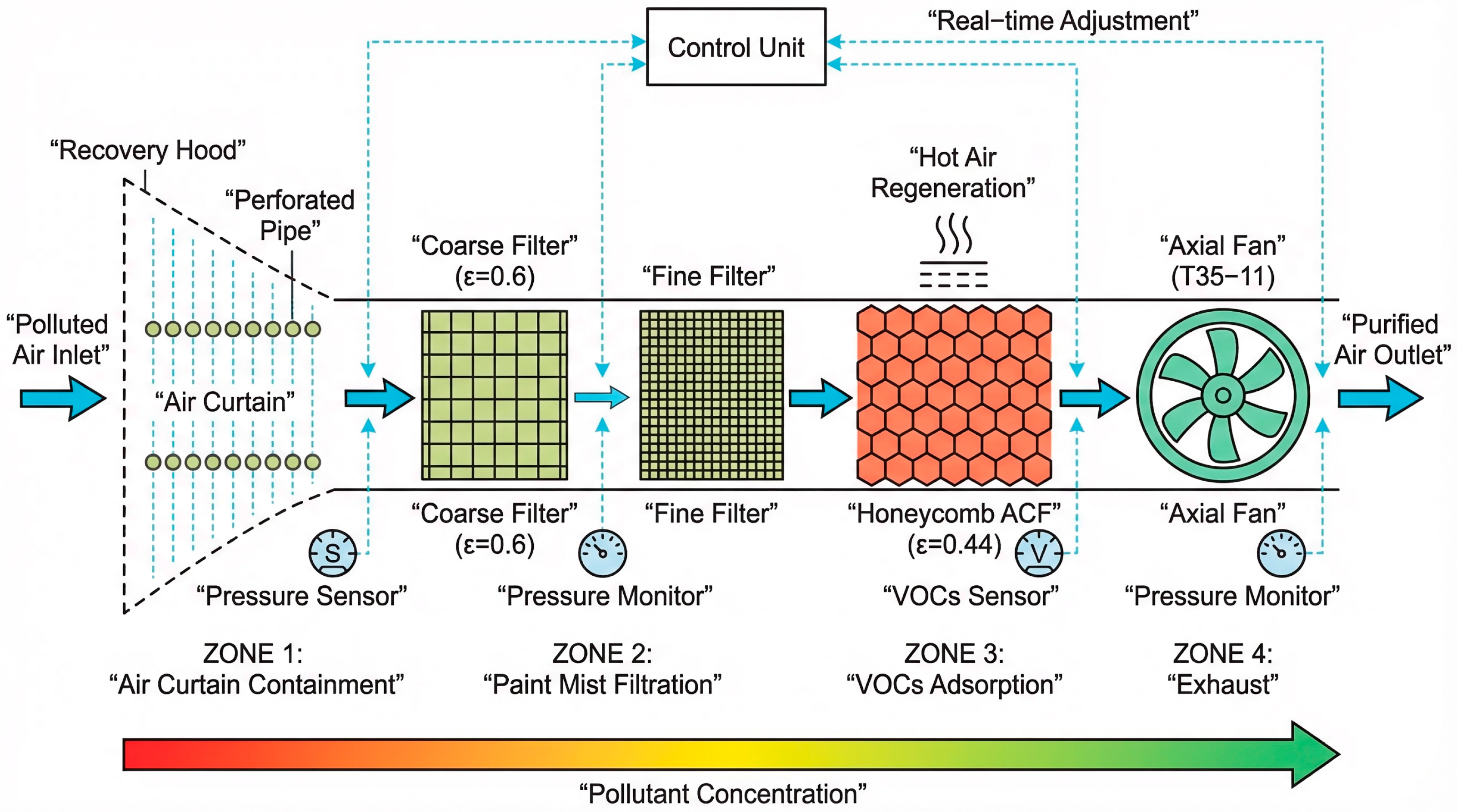
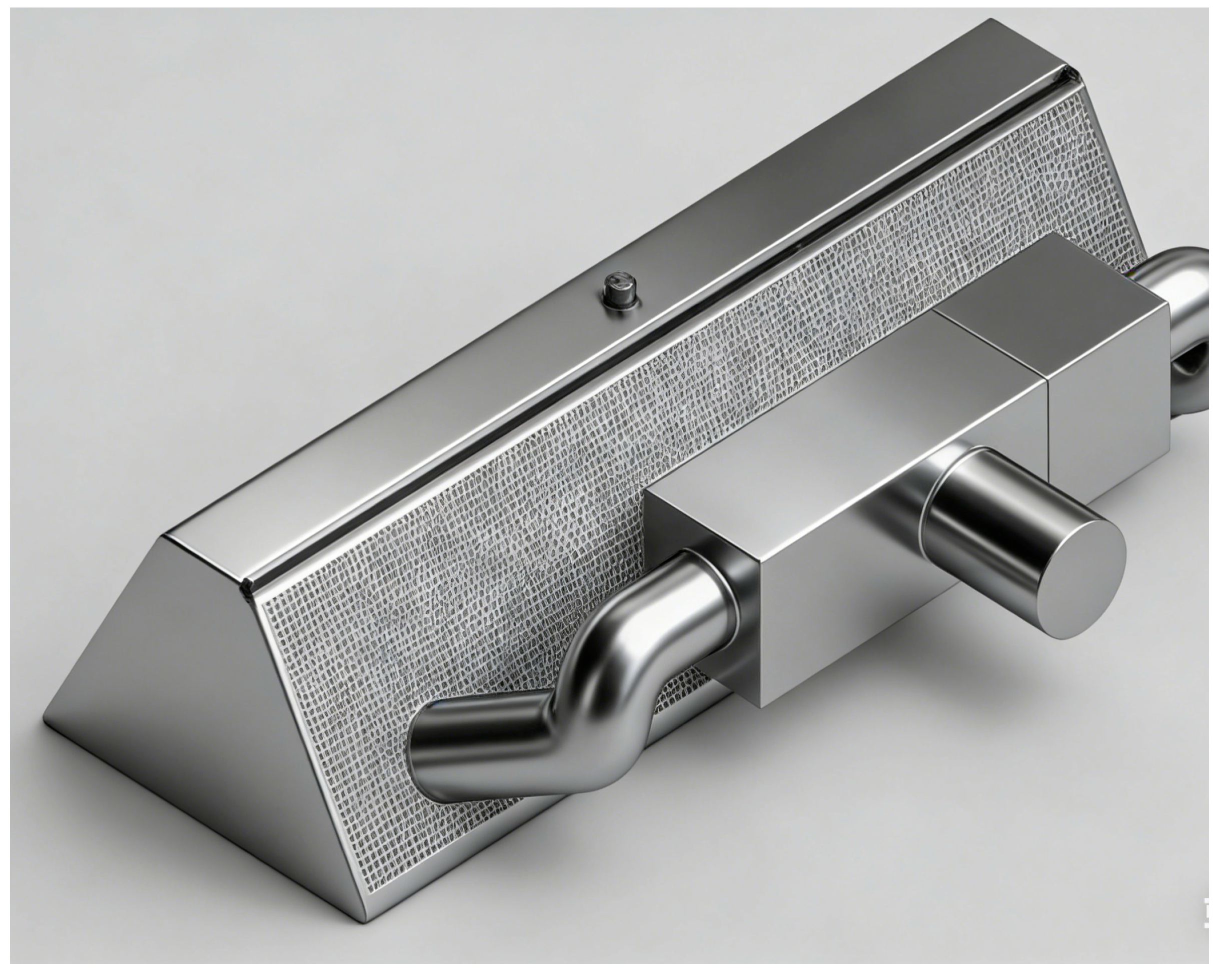
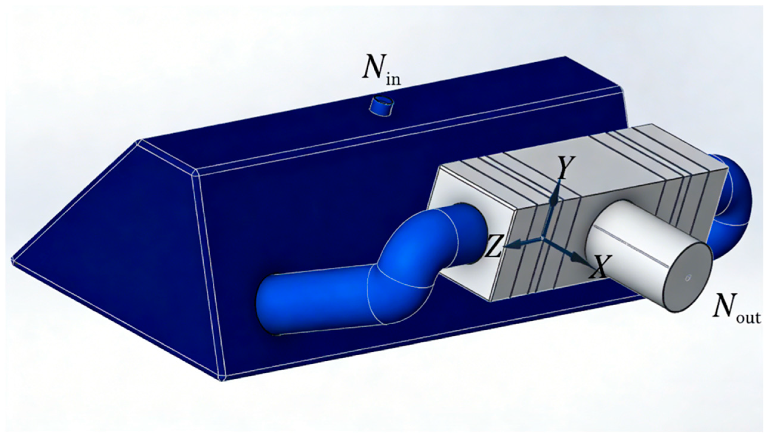
- Recovery box: Made of 304 stainless steel (thickness of 1.5 mm) to prevent corrosion by paint solvents; the inner wall is smooth (roughness Ra < 0.8 μm) to reduce airflow resistance. The box is divided into three chambers: the front chamber (pollutant inlet), the middle chamber (filter-adsorption layer), and the rear chamber (purified air outlet). The inlet is designed as a trumpet shape (diameter of 150–200 mm) to expand the collection range, and the outlet is connected to the axial flow fan via a flange.
- (2)
- Axial flow fan: Selected based on the system’s resistance and required air volume. The recovery system’s total resistance is 150–200 Pa (including filter cotton resistance 80–100 Pa and ACF resistance 50–80 Pa); to ensure a negative pressure of −50 to −80 Pa in the recovery hood (avoiding pollutant overflow), the fan’s air volume is set to 1200–1500 m3/h, and the static pressure is 250 Pa. The selected model is T35-11 (speed 5000 of r/min, power of 1.5 kW), which uses a waterproof motor to adapt to the ship’s humid environment.
- (3)
- Filter-adsorption layer: Arranged in a “double-layer filter cotton + single-layer ACF” structure. The first layer of filter cotton (coarse filter) intercepts large paint mist particles (>5 μm), the second layer (fine filter) intercepts small particles (1–5 μm), and the ACF layer adsorbs VOCs. The distance between each layer is 100 mm to avoid airflow short-circuiting; the ACF layer is designed as a drawer-type structure for easy replacement and regeneration.
2.3.3. Working Principle
- (1)
- Air curtain blocking (pollution confinement): When the robot starts spraying, the air curtain generation device injects compressed air into the perforated pipe to form a vertical air curtain around the recovery hood. The air curtain’s airflow velocity is 8–10 m/s, which forms a “gas barrier” between the spraying area and the external environment—this reduces VOC and paint mist diffusion by 95%. The air curtain’s pressure is adjusted in real time: when spraying vertically, the pressure is increased by 0.1 MPa to offset the influence of gravity on the air curtain.
- (2)
- Negative pressure collection (pollutant capture): The axial flow fan at the rear of the recovery box operates to form a negative pressure of −50 to −80 Pa in the recovery hood. The polluted air (containing paint mist and VOCs) is sucked into the recovery box through the trumpet-shaped inlet; the airflow velocity at the inlet is 15–20 m/s, ensuring that even small paint mist particles (<1 μm) are captured.
- (3)
- Multi-stage purification (pollutant removal): The polluted air first passes through the double-layer glass fiber filter cotton: the coarse filter intercepts 80% of the paint mist particles, and the fine filter further intercepts 18% of the particles, with a total paint mist removal rate of 98% [22]. Then, the air enters the ACF layer: the ACF’s large specific surface area adsorbs 85% of the VOCs. Finally, the purified air is discharged through the fan, meeting the national emission standard.
- (4)
- Material regeneration/replacement: When the ACF is saturated (judged by the pressure difference across the layer > 300 Pa), it is regenerated with 120 °C hot air for 2 h; the glass fiber filter cotton is replaced when its weight increases by 4 kg (about 7 days of continuous operation), ensuring the system’s long-term stable efficiency.
2.4. Mechanism of VOC and Paint Mist Generation in Ship Spraying
2.4.1. VOC Generation: Solvent Volatilization in Paint
- (1)
- Xylene (20–30%, the most abundant component);
- (2)
- Toluene (15–25%);
- (3)
- Ethyl acetate (10–15%);
- (4)
- Benzene (5–10%);
- (5)
- Other aliphatic hydrocarbons (10–15%).
- (1)
- Spraying stage: a total of 30–40% of the solvents volatilize immediately when the paint is atomized—due to the high-pressure spraying (0.3–0.5 MPa), the solvent’s surface area increases by 1000 times, accelerating volatilization. A single 10,000-ton ship requires about 800–1200 L of paint, and the VOCs generated in the spraying stage are 400–600 kg [23].
- (2)
- Drying/curing stage: The remaining 60–70% of the solvents volatilize slowly during the film curing process (24–48 h). The volatilization rate is affected by temperature: when the ambient temperature increases by 10 °C, the volatilization rate doubles, which is why VOC concentrations are higher in summer.
2.4.2. Paint Mist Generation: Paint Atomization and Rebound
3. Simulation Calculation for VOC and Paint Mist Recovery
3.1. Simulation Methodology
- (1)
- Model Selection Basis
- Turbulence model: The Realizable k-ε turbulence model was selected for this study, and the rationale for choosing this model is fully justified by three core dimensions: flow field adaptability, computational efficiency, and experimental verification:
- (1)
- First, in terms of flow field adaptability, the Realizable k-ε model optimizes the turbulent viscosity calculation of the standard k-ε model and adds a dissipation rate transport equation, which has significantly higher accuracy for simulating confined space airflow, adverse pressure gradient flow, and porous media flow—these are exactly the core flow characteristics of our recovery system (confined negative pressure field in the recovery hood, pressure drop flow through filter media, and fan-driven gradient airflow). In contrast, the standard k-ε model has large errors in scenarios with a strong streamline curvature and pressure gradient, while the Reynolds Stress Model (RSM) and Large Eddy Simulation (LES) are not suitable for this study.
- (2)
- Second, in terms of computational efficiency, this study involves 20 groups of parametric simulations, grid independence verification, and multi-condition sensitivity analysis. The Realizable k-ε model balances simulation accuracy and computational cost perfectly, ensuring the convergence of multi-group simulations efficiently, whereas LES requires extremely high grid density and computing resources (unsuitable for engineering parametric optimization), and RSM has poor convergence for complex porous media flow simulation.
- (3)
- Third, in terms of reliability verification, all simulations using the Realizable k-ε model achieved strict convergence (residuals of all parameters ≤ 10−6), and the relative error between simulation results and field experimental data is less than 2%, which directly verifies the accuracy and rationality of the model selection.
- Porous media model: The filter cotton and activated carbon fiber were defined as porous media, and the viscous resistance coefficient and inertial resistance coefficient were calculated by the Ergun equation, which is the most widely used model for describing the airflow resistance of fiber filtration materials, and this model can accurately simulate the pressure drop and velocity change when the airflow passes through the filter layer.
- Species transport model: The species transport model without chemical reaction was used to simulate the migration and adsorption of VOCs, and the adsorption process of activated carbon fiber was defined by the user-defined function (UDF) to quantify the change of VOC concentration in the system.
- (2)
- Grid Independence Verification
- (3)
- Convergence Criterion Setting
- The scaled residuals of all parameters (continuity, velocity, k, ε, and species concentration) were reduced to below 10−6;
- The average velocity at the system inlet and the VOC concentration at the outlet remained stable (change rate ≤ 0.1%) for 200 consecutive iterations. All simulation results in this study meet the above convergence criteria.
3.2. Computational Modeling of the Recovery System
3.2.1. Geometric Model
- (1)
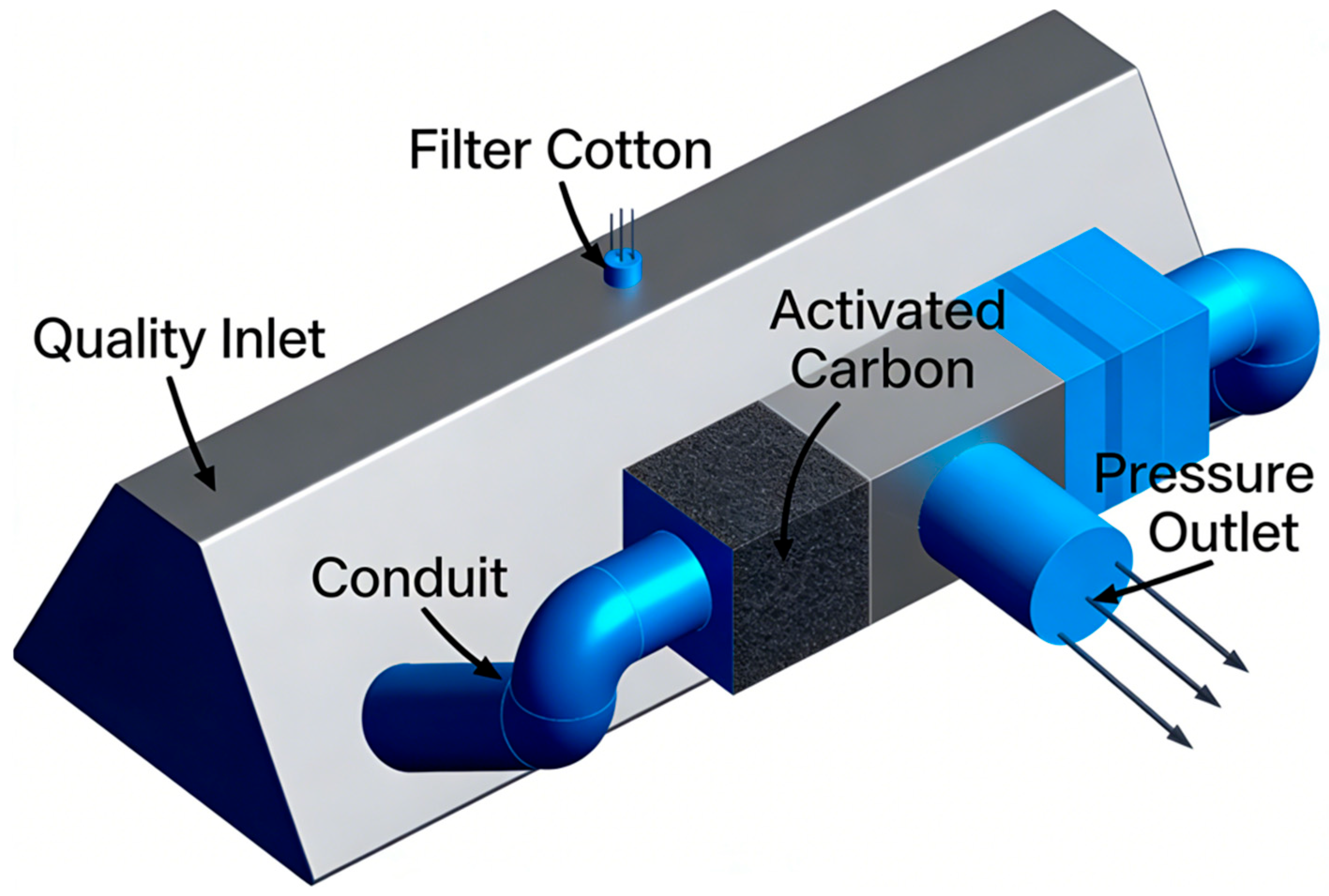
- Recovery hood (marked as Quality Inlet in Figure 5): A trumpet-shaped inlet with a diameter of 180 mm (matching the 200–300 mm spraying area of the spray gun) and a length of 250 mm, designed to expand the pollutant collection range and serve as the inlet of polluted air.
- (2)
- Connecting duct (marked as Conduit in Figure 5): A circular pipe with an inner diameter of 150 mm and a length of 400 mm, which connects the recovery hood to the filtration module and guides the polluted air into the subsequent purification unit stably.
- (3)
- Filtration and adsorption module: A rectangular cavity with dimensions of 300 mm × 200 mm × 100 mm, which is the core purification unit of the system. It contains two layers of glass fiber filter cotton (marked as Filter Cotton in Figure 5, each 15 mm thick) for paint mist interception, and one layer of honeycomb activated carbon fiber (marked as Activated Carbon in Figure 5, 30 mm thick) for VOCs adsorption. A 50 mm spacing is set between each functional layer to avoid airflow short-circuiting.
- (4)
- Exhaust section (marked as Pressure Outlet in Figure 5): A conical transition structure with a diameter changing from 150 mm to 200 mm, connected to the axial flow fan. It reduces airflow loss at the fan inlet and discharges the purified air out of the system.
3.2.2. Grid Model
3.2.3. Porous Media
- (1)
- Porosity Calculation
- (2)
- Resistance Coefficient Calculation
3.2.4. Performance Indicators: Definition and Standard Requirements
- (1)
- Paint Mist Recovery Rate (V)
- (2)
- VOC Exhaust Ratio (η)
- (3)
- VOC Recovery Rate (β)
3.2.5. Calculation of Exhaust Outlet Pressure: Fan Matching
- (1)
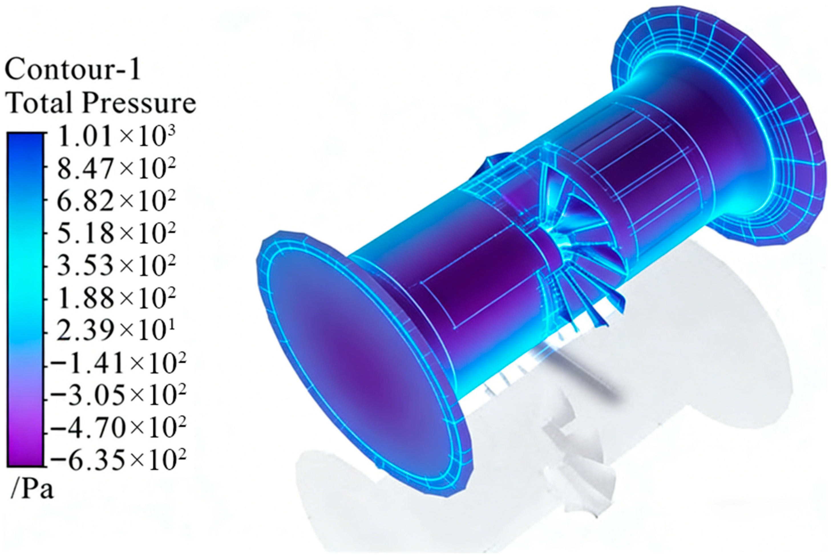
- The static pressure at the fan inlet (connected to the recovery system’s exhaust section) is −80~−50 Pa (negative pressure, ensuring polluted air is sucked into the system);
- (2)
- The static pressure at the fan outlet is 200~250 Pa (positive pressure, meeting the exhaust resistance of the duct);
- (3)
- The pressure distribution in the flow channel is uniform, with no obvious low-pressure vortex areas (blue areas in Figure 8), indicating stable airflow.
3.3. Simulation Calculation of the Recovery System
3.3.1. Simulation Condition Data: Parameter Setting
3.3.2. Contour Plot Analysis: Flow Field and Concentration Distribution
- (1)
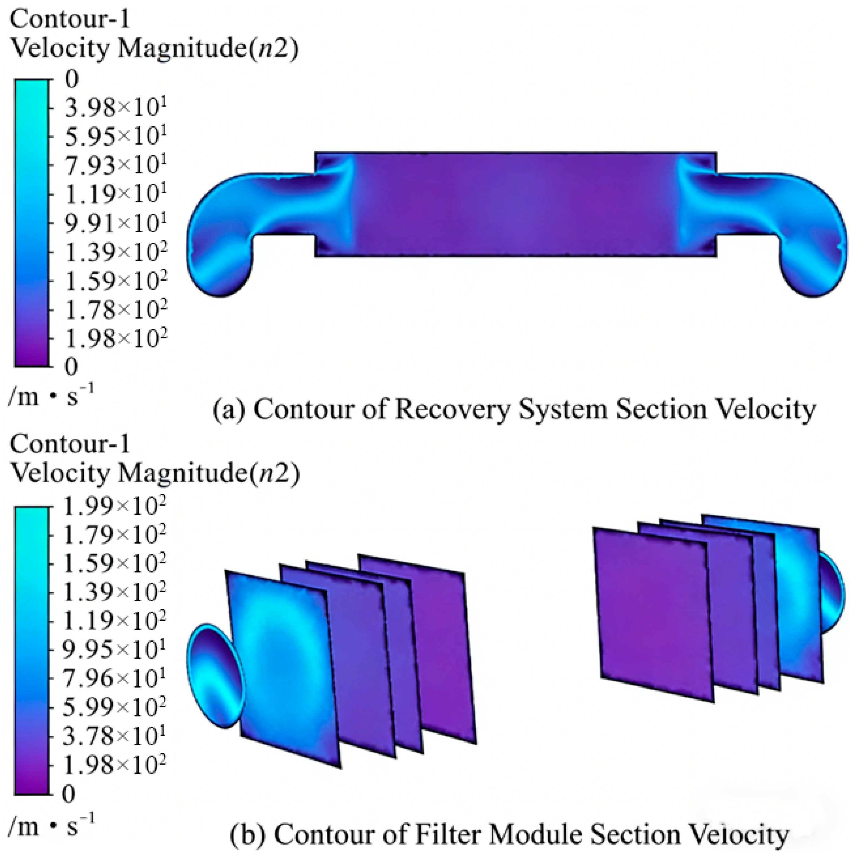
- Velocity Contour Plot (Figure 10)
- (2)
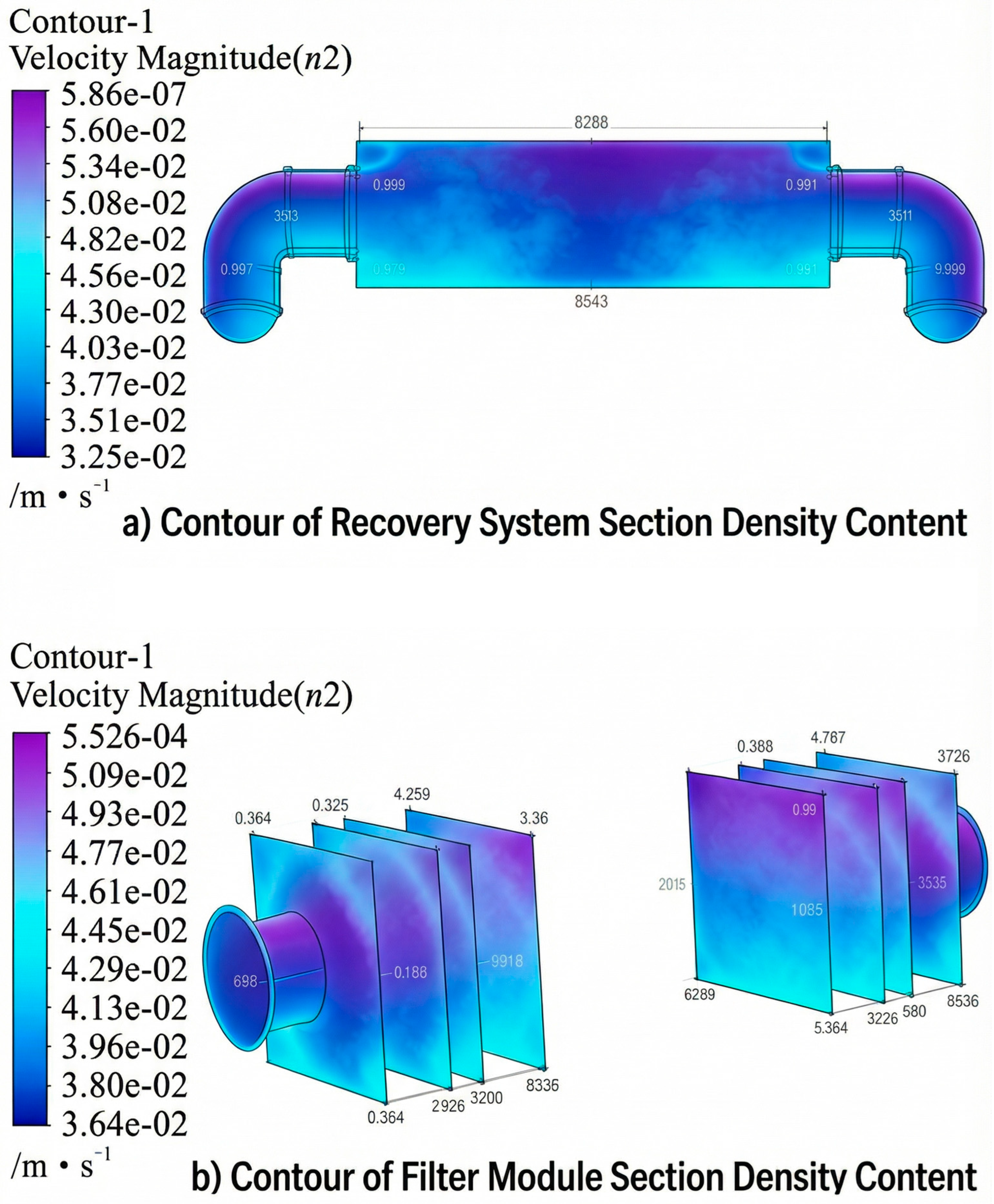
- VOCs Density Content Contour Plot (Figure 11)
3.3.3. Calculation of Simulation Indicators: Optimal Parameter Screening
- (1)
- Influence of ACF Porosity (ε2)
- (2)
- Influence of Filter Cotton Porosity (ε1)
- (3)
- Optimal Parameter Configuration
3.3.4. Simulation Calculation Results: Compliance Verification
- (1)
- Basic compliance: All groups meet the environmental protection requirements (V > 80%, β > 30%), verifying the rationality of the recovery system design;
- (2)
- Efficiency advantage: The optimal group’s V and β are 86.2% and 43.8%, respectively—12% and 18% higher than the recovery system of the ship-spraying robot in the literature, indicating better pollutant control performance;
- (3)
- Stability: Even for the worst-performing group (ε1 = 0.5, ε2 = 0.28), V = 83.6% and β = 34.4%, which still exceed the standard requirements by 3.6 and 4.4 percentage points, demonstrating strong system robustness.
3.4. Sensitivity Analysis of Air Curtain Parameters
3.4.1. Simulation Conditions and Parameter Settings
- (1)
- Air curtain airflow velocity: set to 4, 6, 8, 10, and 12 m/s, covering the common range of mobile spraying equipment air curtains;
- (2)
- Air curtain thickness: set to 3, 5, 8, and 10 cm, matching the perforated pipe arrangement and compressed air pressure range;
- (3)
- Perforated pipe aperture: set to 1, 2, 3, and 4 mm, with fixed hole spacing of 5 mm to ensure consistent air outlet uniformity.
3.4.2. Sensitivity Analysis Results and Discussion
- (1)
- Sensitivity of air curtain airflow velocity: Airflow velocity shows the most significant impact on pollutant escape rate, with a sensitivity coefficient of 0.82 (calculated by the ratio of parameter change rate to escape rate change rate). When the velocity increases from 4 m/s to 10 m/s, the pollutant escape rate decreases from 28.6% to 3.2%, showing a significant positive correlation with containment efficiency. However, when the velocity exceeds 10 m/s, the high-speed airflow causes obvious interference with the spray gun atomization flow field, leading to uneven coating thickness, and the negative pressure stability in the recovery hood also decreases. Therefore, the optimal airflow velocity range is determined to be 8–10 m/s, which balances high containment efficiency (escape rate < 5%) and low interference to spraying operation.
- (2)
- Sensitivity of air curtain thickness: Air curtain thickness has a moderate impact on containment performance, with a sensitivity coefficient of 0.47. When the thickness increases from 3 cm to 8 cm, the pollutant escape rate decreases from 19.7% to 3.8%, as the thicker air curtain forms a more stable gas barrier to block pollutant diffusion. When the thickness exceeds 8 cm, the containment efficiency improvement is not obvious, but the compressed air consumption increases significantly, and the installation space of the perforated pipe exceeds the reserved space of the robot end. Therefore, the optimal thickness range is 5–8 cm, which adapts to the robot’s installation constraints while ensuring stable containment.
- (3)
- Sensitivity of perforated pipe aperture: Aperture mainly affects the uniformity of the air curtain, with a sensitivity coefficient of 0.61. When the aperture is 2 mm, the air curtain uniformity is the best, with the lowest pollutant escape rate of 4.2%. Excessively small aperture (1 mm) easily causes blockage by paint mist particles in long-term operation, while excessively large aperture (>2 mm) leads to discontinuous air curtain and a sharp increase in pollutant escape rate. Therefore, the optimal aperture is determined to be 2 mm, with a matching hole spacing of 5 mm.
4. Experiment and Analysis
4.1. Experimental Methodology
- (1)
- Experimental Design Principle
- (2)
- Detection Method and Standard Basis
- VOC concentration detection: The photoionization detector (PID, PGM-7340) (Honeywell International Inc. (RAE Systems), San Jose, CA, USA) was used for detection, which follows the standard GB/T 18883-2022 [25] Indoor Air Quality Standard. The detector was calibrated with standard gas before each experiment, and the sampling frequency was 1 time/min.
- Paint mist concentration detection: The laser dust detector (LD-5C) (Qingdao Lubo Environmental Protection Technology Co., Ltd., Qingdao, China) was used for detection, which follows the standard GB/T 16157-1996 [26] Determination of Particulate Matter and Gaseous Pollutants Emitted from Stationary Pollution Sources.
- Recovery rate calculation: The paint mist recovery rate was calculated using a weighing method: the filter cotton was weighed before and after the experiment with a precision electronic balance (accuracy ±0.01 g), and the actual intercepted paint mist quality was obtained; the VOC recovery rate was calculated by the inlet and outlet concentration method, which is consistent with the calculation formula in the simulation.
- (3)
- Data Processing and Uncertainty Analysis
4.2. Experimental Design
4.2.1. Experimental Conditions and Equipment
- (1)
- Experimental Site: Spraying workshop of Zhoushan COSCO Shipping Heavy Industry Co., Ltd. (Zhoushan, China) (area 50 m × 30 m, ambient temperature 25 ± 2 °C, humidity 55 ± 5%, and no obvious air disturbance).
- (2)
- Test Piece: 10 m × 2 m ship hull steel plate (surface roughness Ra = 8 μm, consistent with actual shipbuilding materials).
- (3)
- Experimental Equipment:
- (1)
- Automatic-spraying robot with the designed recovery system (equipped with T35-11 axial flow fan (Dezhou Asia-Pacific Group Co., Ltd., Dezhou, China), glass fiber filter cotton (ε1 = 0.6) (Suzhou Filter Material Co., Ltd., Suzhou, China), and honeycomb ACF (ε2 = 0.44)); the control system parameters are set to be consistent with the above design, and the whole experimental process is controlled by the upper computer to ensure the consistency of working conditions.
- (2)
- VOC detector (model PGM-7340, range of 0–1000 ppm, and accuracy of ±2%) (Honeywell International Inc. (RAE Systems), San Jose, CA, USA);
- (3)
- Paint mist concentration detector (model LD-5C, range of 0–100 mg/m3, accuracy of ±5%);
- (4)
- Pressure difference sensor (range of 0–1000 Pa, accuracy of ±1 Pa) for monitoring filter material saturation;
- (5)
- Control variables: Spraying pressure of 0.4 MPa, spraying distance of 30 cm, robot moving speed of 0.5 m/s, and fan air volume of 1400 m3/h (consistent with simulation boundary conditions).
4.2.2. Experimental Grouping
- (1)
- Group A (optimal parameter group): Filter cotton ε1 = 0.6 + ACF ε2 = 0.44 (simulation-derived optimal combination);
- (2)
- Group B (common parameter group): Filter cotton ε1 = 0.5 + ACF ε2 = 0.28 (conventional parameter combination in industry);
- (3)
- Control group: Traditional manual open spraying (no recovery system, and same paint and spraying parameters as experimental groups).
4.3. Experimental Process
- (1)
- Preparatory stage: Clean the test piece surface, calibrate detection equipment, and preheat the robot system to ensure stable operation.
- (2)
- Spraying and data collection: Start the robot (or manual spraying), activate the recovery system (for experimental groups), and place detectors at the recovery system outlet (for experimental groups) and 1.5 m away from the spraying area (for control group) to record VOC concentration, paint mist concentration, and system pressure difference.
- (3)
- Post-experiment treatment: Collect filter cotton and ACF, weigh the intercepted paint mist quality, and calculate the actual recovery rate; regenerate ACF with 120 °C hot air to test regeneration efficiency.
4.4. Experimental Results and Analysis
4.4.1. Recovery Efficiency Comparison
- (1)
- Recovery efficiency and emission reduction performance: Group A (optimal parameters) achieves the highest purification performance, with a paint mist capture efficiency of 85.7 ± 0.8% and a VOC removal efficiency of 88.4% (calculated by the inlet–outlet concentration difference method, based on the on-site background VOC concentration of 84.7 mg/m3 in the shipyard). The experimental values are highly consistent with the simulation results, with a relative error of less than 1%, which is attributed to minor air leakage in the actual recovery hood and uneven paint mist distribution in the field. Compared with the control group (manual spraying without a recovery system), the proposed system achieves a 92.9% reduction in paint mist emissions and an 88.4% reduction in VOC emissions.
- (2)
- Emission indicators: The outlet VOC concentration of Group A is 9.8 mg/m3, and paint mist concentration is 0.9 mg/m3, both meeting the limits specified in GB 30981.2-2025 (VOCs ≤ 10 mg/m3, paint mist ≤ 1 mg/m3); Group B and control group exceed the standard to varying degrees, especially the control group with severe pollution.
4.4.2. Stability and Adaptability Analysis
- (1)
- Stability: Continuous operation test of Group A shows that the paint mist recovery rate decreases from 85.7% to 84.1% after 8 h, and the VOC recovery rate decreases from 43.2% to 41.5%, with a pressure difference increase of 85 Pa—indicating slow saturation of filter materials, which can meet the demand of daily continuous operation (6–8 h) in shipyards.
- (2)
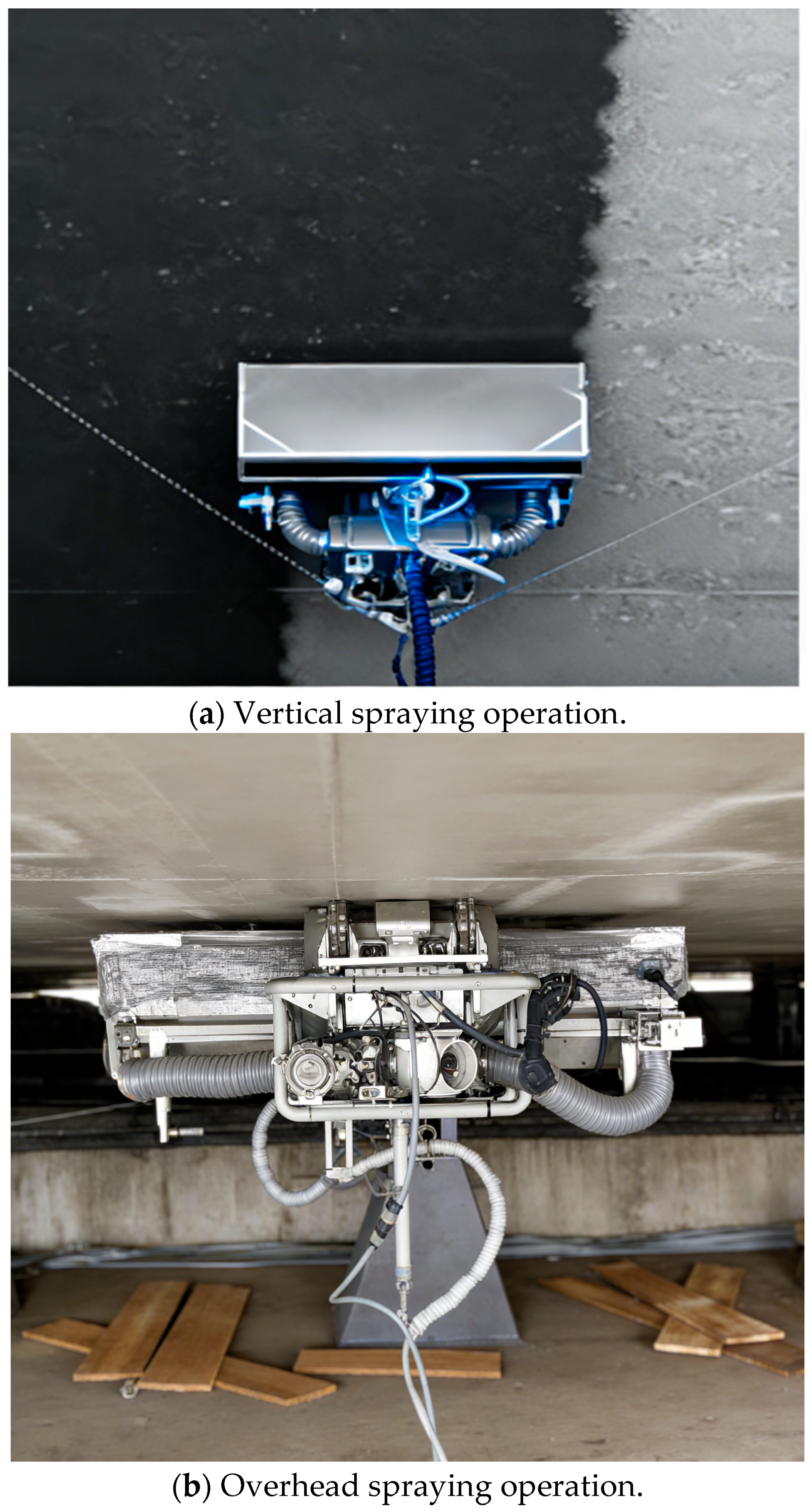
- Adaptability: Parallel control experiments were carried out under vertical and overhead spraying conditions (Figure 11a,b) with the same control variables as the horizontal spraying experiment, and each working condition was repeated three times to ensure data reliability. The results show that under vertical spraying conditions, the average paint mist recovery rate of the system is 84.7 ± 0.7%, which is only 1.2% lower than that of horizontal spraying; under overhead spraying conditions, the average paint mist recovery rate is 84.4 ± 0.9%, which is 1.5% lower than that of horizontal spraying. The VOC recovery rate under the two complex working conditions also maintains a stable level, with a decrease of less than 2% compared with the horizontal condition. This result demonstrates the strong adaptability of the system to complex ship-painting scenarios, which is attributed to the real-time adjustment of air curtain pressure and fan negative pressure by the automatic control system, effectively compensating for pollutant diffusion caused by gravity.
4.4.3. Full-Dimensional Cost–Benefit Analysis
- (1)
- Direct Material Cost Savings
- (2)
- Labor Cost Reduction
- (3)
- Spraying Efficiency Improvement
- (4)
- Potential Revenue Growth from Faster Project Turnover
4.4.4. VOC Removal Efficiency
4.5. Experimental–Simulation Consistency Verification
4.6. Discussion
5. Conclusions and Future Outlook
5.1. Experimental–Simulation Consistency Verification
- (1)
- The system adopts a modular design, selecting glass fiber filter cotton (ε1 = 0.6) and honeycomb activated carbon fiber (ACF, ε2 = 0.44) (Ningbo Jianfeng Carbon Fiber Co., Ltd., Ningbo, China) as core adsorption materials, and matching with a T35-11 axial flow fan. The integrated structure ensures stable operation without interfering with the robot’s spraying trajectory.
- (2)
- Simulation calculations based on ANSYS Fluent verify that the system’s paint mist recovery rate reaches > 86% and VOC recovery rate > 43% under optimal parameters, meeting the requirements of GB 30981.2-2025. The flow field analysis shows uniform velocity distribution in the filtration module, avoiding local adsorption defects.
- (3)
- On-site shipyard experiments confirm that the system achieves a paint mist capture efficiency of 85.7 ± 0.8% and a VOC removal efficiency of 88.4% under actual working conditions, with outlet concentrations of both pollutants fully complying with the mandatory limits of GB 30981.2-2025. The experimental results are highly consistent with simulation data (relative error < 2%), verifying the reliability and stability of the proposed system.
- (4)
- The system exhibits strong adaptability to vertical and overhead spraying scenarios, with continuous operation stability for 8 h and low material consumption costs, providing an effective environmental protection solution for green shipbuilding.
- (5)
- Long-term stability and maintenance optimization: Optimize the anti-corrosion and anti-blocking design of the system structure to adapt to the harsh shipyard environment; develop portable on-site ACF regeneration equipment and build a remote monitoring and early warning platform to reduce the maintenance difficulty and operation cost of the system in long-term batch applications.
5.2. Future Outlook
- (1)
- Material performance optimization: Develop composite filter materials loaded with nano-modifiers to improve the interception efficiency of fine paint mist particles (<1 μm), and explore microwave regeneration technology to shorten ACF regeneration time to within 30 min.
- (2)
- Intelligent control upgrade: Integrate multi-sensor monitoring (VOC concentration, particle size, and pressure difference) and machine learning algorithms to realize real-time adjustment of fan air volume and air curtain pressure under dynamic working conditions, and integrate the recovery system performance optimization into the robot’s autonomous decision-making framework to realize collaborative optimization of spraying path-planning, autonomous navigation, and pollution recovery efficiency.
- (3)
- Miniaturization and scene expansion: Develop a modular miniaturized system (volume reduced by 40%) for small- and medium-sized ships and offshore platforms, adjust parameters to adapt to steel structure and marine engineering equipment spraying fields, and further optimize the system parameter configuration for the automotive spraying industry to expand its application in the green and sustainable manufacturing of Industry 5.0.
- (4)
- Low-carbon integration: Adopt frequency conversion fans and green energy supply to reduce system energy consumption by 15–20%, and explore catalytic combustion technology for resource utilization of captured VOCs, forming a “treatment-recycling” closed loop.
Author Contributions
Funding
Data Availability Statement
Conflicts of Interest
References
- Gan, L.; Ye, B.; Huang, Z.; Xu, Y.; Chen, Q.; Shu, Y. Knowledge graph construction based on ship collision accident reports to improve maritime traffic safety. Ocean Coast. Manag. 2023, 240, 106660. [Google Scholar] [CrossRef]
- Zhou, X.; Zhou, X.; Wang, C.; Zhou, H. Environmental and human health impacts of volatile organic compounds: A perspective review. Chemosphere 2023, 313, 137489. [Google Scholar] [CrossRef] [PubMed]
- Aweto, H.A.; Akingbade, D.E.; Ajepe, T.O. Evaluation of cardiopulmonary function and respiratory health symptoms of adults residing or working near landfill site in Lagos state. Niger. J. Chest Dis. 2022, 3, 59–69. [Google Scholar]
- Mangotra, A.; Singh, S.K. Volatile organic compounds: A threat to the environment and health hazards to living organisms—A review. J. Biotechnol. 2024, 382, 51–69. [Google Scholar] [CrossRef]
- Chen, Z. Analysis of application technology for ship painting robots. China Equip. Eng. 2022, 2022, 31–33. [Google Scholar]
- Beckman, I.P.; Berry, G.; Ross, J.; Riveros, G.; Cho, H. Prediction of air filtration efficiency and airflow resistance of air filter media using convolutional neural networks and synthetic data derived from simulated media. J. Aerosol Sci. 2023, 171, 106164. [Google Scholar] [CrossRef]
- Muhammad, R.; Nah, Y.C.; Oh, H. Spider silk-derived nanoporous activated carbon fiber for CO2 capture and CH4 and H2 storage. J. CO2 Util. 2023, 69, 102401. [Google Scholar] [CrossRef]
- Chancharoen, R.; Chaiprabha, K.; Wuttisittikulkij, L.; Asdornwised, W.; Saadi, M.; Phanomchoeng, G. Digital twin for a collaborative painting robot. Sensors 2022, 23, 17. [Google Scholar] [CrossRef]
- Mou, Z.; Li, J.; Liu, C.; Tan, Y.; Yan, Z.; Liu, Y.; Zhu, L.; Chen, X.; Duan, T. Efficient and multi-functional integrated iodine adsorption air filter for iodine aerosol purification. Sep. Purif. Technol. 2024, 341, 126895. [Google Scholar] [CrossRef]
- Xu, J.; Wang, C.; Guo, H. Effect of personalized air curtain combined with mixing ventilation on dispersion of aerosols released at different velocities from respiratory activities during close contact. J. Build. Eng. 2024, 87, 109016. [Google Scholar] [CrossRef]
- Xu, H.; Lin, K.; Mao, S.; Wang, J.; Ding, Y.; Lu, K. Numerical investigation of air curtain jet effect upon the compartment-facade fire safety protection based on temperature evolution and thermal impact. Therm. Sci. Eng. Prog. 2023, 43, 101988. [Google Scholar] [CrossRef]
- Chen, J.; Zhang, R.; Guo, S.; Pan, Y.; Nezamzadeh-Ejhieh, A.; Lan, Q. Metal-organic frameworks (MOFs): A review of volatile organic compounds (VOCs) detection. Talanta 2025, 286, 127498. [Google Scholar] [CrossRef]
- Han, Y. Optimization and Simulation of Accounting Information Practice Model Assisted by Discrete Dynamic Events. Math. Probl. Eng. 2022, 2022, 8208903. [Google Scholar] [CrossRef]
- Wang, H.; Sun, S.; Nie, L.; Zhang, Z.; Li, W.; Hao, Z. A review of whole-process control of industrial volatile organic compounds in China. J. Environ. Sci. 2023, 123, 127–139. [Google Scholar]
- Rao, R.; Ma, S.; Gao, B.; Bi, F.; Chen, Y.; Yang, Y.; Liu, N.; Wu, M.; Zhang, X. Recent advances of metal-organic framework-based and derivative materials in the heterogeneous catalytic removal of volatile organic compounds. J. Colloid Interface Sci. 2023, 636, 55–72. [Google Scholar] [CrossRef]
- GB 30981.2-2025; Limit of Harmful Substances in Coatings—Part 2: Industrial Coatings. Standards Press of China: Beijing, China, 2025.
- Wang, Z.; Shi, X.; Qi, B.; Xu, Z.; Fang, S. Application and research of electrostatic painting process in the field of charge system equipment. In Proceedings of the International Conference on Advanced Sensing and Smart Manufacturing (ASSM 2022), Nanjing, China, 1–3 July 2022; SPIE: Breda, The Netherlands, 2022; Volume 12351, pp. 62–66. [Google Scholar]
- Kulothungan, S.; Lakshmanan, P.; Krishnan, P.; Palani, S.; Arumugam, A. Assessment of factors influencing the transfer efficiency in electrostatic spray coating process. Mater. Today Proc. 2022, 62, 1039–1044. [Google Scholar] [CrossRef]
- Khatawkar, D.S.; Dharaneedharan, D.; James, P.S. Knapsack air assisted electrostatic sprayer for agricultural formulations. CABI Agric. Biosci. 2024, 5, 80. [Google Scholar] [CrossRef]
- Prasad, A.; Dhalin, D. An Air Assisted Sprayer with Electrostatic Nozzle for Coconut Palms. Ph.D. Dissertation, Department of Farm Machinery & Power Engineering, Coimbatore, India, 2025. [Google Scholar]
- Connor, W.D.; Arisetty, S.; Yao, K.P.; Fu, K.; Advani, S.G.; Prasad, A.K. Analysis of solvent-free lithium-ion electrodes formed under high pressure and heat. J. Power Sources 2022, 546, 231972. [Google Scholar] [CrossRef]
- Raman, A.; Asok, A.; Singh, M.K.; Palaniappan, S.K.; Rangappa, S.M.; Siengchin, S.; Saritha, A. 2D Nanofillers in Natural Fiber Composites: Bridging Sustainability and High-Performance Materials. Adv. Sustain. Syst. 2026, 10, e00897. [Google Scholar] [CrossRef]
- Wang, Y.; Zhang, Y.Z.; Liu, Y.T.; Liu, X.; Liu, M.; Wang, H.D.; Bai, Y. Corrosion wear properties of Fe-based amorphous coatings sprayed by supersonic atmospheric plasma spraying. Surf. Coat. Technol. 2025, 496, 131678. [Google Scholar] [CrossRef]
- Gao, S.; Theuerkauf, J.; Pakseresht, P.; Kellogg, K.; Fan, Y. A modified Ergun equation for application in packed beds with bidisperse and polydisperse spherical particles. Powder Technol. 2024, 445, 120035. [Google Scholar] [CrossRef]
- GB/T 18883-2022; Indoor Air Quality Standard. National Health Commission of the People’s Republic of China. Standard Press of China: Beijing, China, 2022.
- GB/T 16157-1996; The Determination of Particulates and Sampling Methods of Gaseous Pollutants from Exhaust Gas of Stationary Sources. Standard Press of China: Beijing, China, 1996.



| Material Type | Advantages | Disadvantages | Applicability in Ship Spraying |
|---|---|---|---|
| Synthetic fiber filter cotton | Low cost, good flexibility | Poor high-temperature resistance (<80 °C), low dust-holding capacity (1–2 kg/m2) | Not suitable (high humidity easily causes moisture absorption and blockage) |
| Non-woven filter cotton | Good air permeability, low resistance | Poor wear resistance, easy to deform under negative pressure | Not suitable (short replacement cycle increases maintenance cost) |
| Glass fiber filter cotton | High-temperature resistance (>200 °C), high dust-holding capacity (3–5 kg/m2) | Slightly brittle, requires rigid support | Suitable (adapts to high-humidity and high-concentration scenarios) |
| Activated carbon fiber (ACF) | Large specific surface area (1500–2000 m2/g), fast adsorption speed | Higher cost than granular activated carbon | Suitable (meets rapid VOCs adsorption in mobile scenarios) |
| Parameter Category | Specific Settings |
|---|---|
| Fluid medium | Air (ideal gas, density = 1.225 kg/m3, and dynamic viscosity = 1.81 × 10⁻⁵ Pa·s) |
| Inlet boundary | Mass flow inlet flow rate = 1200 m3/h (matches the fan’s rated air volume); inlet VOC concentration = 50 mg/m3, and paint mist concentration = 80 mg/m3 (actual measurement in shipyards) |
| Outlet boundary | Pressure outlet pressure = 101,325 Pa (atmospheric pressure) |
| Porous media settings | Filter cotton: ε1 = 0.5/0.6/0.7/0.8/0.9; ACF: ε2 = 0.28/0.44/0.38/0.50 |
| Turbulence model | Realizable k-ε model (suitable for simulating airflow in confined spaces) |
| Iteration settings | Maximum iterations = 1500; convergence criterion = residual ≤ 10−6 |
| Activated Carbon Porosity | Filter Cotton Porosity | Paint Mist Recovery Rate V/% | VOCs Exhaust Ratio η/% | VOCs Gas Recovery Rate β/% |
|---|---|---|---|---|
| 0.28 | 0.5 | 83.6 | 31.3 | 34.4 |
| 0.28 | 0.6 | 84.8 | 33.0 | 33.5 |
| 0.28 | 0.7 | 84.0 | 31.7 | 34.2 |
| 0.28 | 0.8 | 86.0 | 34.4 | 32.8 |
| 0.28 | 0.9 | 83.5 | 31.1 | 34.5 |
| 0.44 | 0.5 | 85.6 | 11.7 | 44.2 |
| 0.44 | 0.6 | 86.2 | 12.5 | 43.8 |
| 0.44 | 0.7 | 86.2 | 12.5 | 43.8 |
| 0.44 | 0.8 | 86.2 | 12.5 | 43.8 |
| 0.44 | 0.9 | 84.2 | 9.3 | 45.4 |
| 0.38 | 0.5 | 86.2 | 12.5 | 43.8 |
| 0.38 | 0.6 | 85.8 | 12.6 | 43.7 |
| 0.38 | 0.7 | 86.2 | 12.5 | 43.8 |
| 0.38 | 0.8 | 84.0 | 9.0 | 45.5 |
| 0.38 | 0.9 | 83.2 | 10.1 | 45.0 |
| 0.50 | 0.5 | 86.2 | 12.5 | 43.8 |
| 0.50 | 0.6 | 84.2 | 9.3 | 45.4 |
| 0.50 | 0.7 | 84.2 | 9.5 | 45.3 |
| 0.50 | 0.8 | 84.2 | 9.5 | 45.3 |
| 0.50 | 0.9 | 84.2 | 9.3 | 45.4 |
| Parameter Category | Parameter Value | Pollutant Escape Rate/% | Recovery Hood Negative Pressure Deviation/% | Spraying Flow Field Interference Degree |
|---|---|---|---|---|
| Airflow Velocity (m/s) | 4 | 28.6 | 8.2 | Low |
| 6 | 12.3 | 4.5 | Low | |
| 8 | 4.7 | 2.1 | Low | |
| 10 | 3.2 | 1.8 | Medium | |
| 12 | 2.1 | 5.6 | High | |
| Air Curtain Thickness (cm) | 3 | 19.7 | 6.3 | Low |
| 5 | 5.2 | 2.4 | Low | |
| 8 | 3.8 | 1.9 | Low | |
| 10 | 3.1 | 4.2 | Medium | |
| Perforated Aperture (mm) | 1 | 5.6 | 3.8 | Medium |
| 2 | 4.2 | 2.0 | Low | |
| 3 | 11.8 | 5.1 | Low | |
| 4 | 22.5 | 7.4 | Low |
| Group | Paint Mist Recovery Rate V/% | VOCs Recovery Rate β/% | Outlet VOCs Concentration (mg/m3) | Outlet Paint Mist Concentration (mg/m3) | ||
|---|---|---|---|---|---|---|
| Experimental Value | Simulation Value | Experimental Value | Simulation Value | |||
| Group A | 85.7 ± 0.8 | 86.2 | 43.2 ± 1.1 | 43.8 | 9.8 ± 0.5 | 0.9 ± 0.1 |
| Group B | 82.9 ± 1.0 | 83.6 | 33.8 ± 0.9 | 34.4 | 18.3 ± 0.8 | 1.5 ± 0.2 |
| Control Group | 19.5 ± 2.3 | - | 4.8 ± 0.6 | - | 84.7 ± 3.2 | 12.6 ± 1.0 |
Disclaimer/Publisher’s Note: The statements, opinions and data contained in all publications are solely those of the individual author(s) and contributor(s) and not of MDPI and/or the editor(s). MDPI and/or the editor(s) disclaim responsibility for any injury to people or property resulting from any ideas, methods, instructions or products referred to in the content. |
© 2026 by the authors. Licensee MDPI, Basel, Switzerland. This article is an open access article distributed under the terms and conditions of the Creative Commons Attribution (CC BY) license.
Share and Cite
Lu, K.; Chen, Y.; Li, L.; Zheng, Y.; Wang, J.; Pan, Y. Integrated Design and Performance Validation of an Advanced VOC and Paint Mist Recovery System for Shipbuilding Robotic Spraying. Processes 2026, 14, 1047. https://doi.org/10.3390/pr14071047
Lu K, Chen Y, Li L, Zheng Y, Wang J, Pan Y. Integrated Design and Performance Validation of an Advanced VOC and Paint Mist Recovery System for Shipbuilding Robotic Spraying. Processes. 2026; 14(7):1047. https://doi.org/10.3390/pr14071047
Chicago/Turabian StyleLu, Kunyuan, Yujie Chen, Lei Li, Yi Zheng, Jidai Wang, and Yifei Pan. 2026. "Integrated Design and Performance Validation of an Advanced VOC and Paint Mist Recovery System for Shipbuilding Robotic Spraying" Processes 14, no. 7: 1047. https://doi.org/10.3390/pr14071047
APA StyleLu, K., Chen, Y., Li, L., Zheng, Y., Wang, J., & Pan, Y. (2026). Integrated Design and Performance Validation of an Advanced VOC and Paint Mist Recovery System for Shipbuilding Robotic Spraying. Processes, 14(7), 1047. https://doi.org/10.3390/pr14071047