Review

Catalytic Materials for Hydrogen Generation: Design, Properties, and Applications in Sustainable Energy Systems


Department of Mechanical Engineering, University of Nevada-Reno, Reno, NV 89557, USA
*
Author to whom correspondence should be addressed.
Processes 2026, 14(6), 957; https://doi.org/10.3390/pr14060957
Submission received: 28 January 2026 / Revised: 4 March 2026 / Accepted: 14 March 2026 / Published: 17 March 2026
(This article belongs to the Section Catalysis Enhanced Processes)

Abstract

Catalytic materials are central to the advancement of hydrogen generation technologies, playing a pivotal role in enabling sustainable, carbon-neutral energy systems. Hydrogen can be produced via electrochemical water splitting, thermochemical reforming, or photocatalysis—each imposing unique performance requirements on catalysts in terms of activity, selectivity, stability, and efficiency. While traditional noble metals (e.g., platinum, ruthenium, iridium) provide benchmark catalytic activity, their widespread use is hindered by scarcity, high cost, and limited long-term durability. Consequently, researchers have increasingly focused on earth-abundant alternatives such as transition metals (Ni, Co, Fe, Mo), alloys, metal oxides, carbides, sulfides, nitrides, and carbon-based systems. Among these, two-dimensional materials, particularly the MXene family, have attracted significant attention due to their metallic conductivity, layered structure, and tunable surface chemistry. These features enable rapid charge transfer and abundant active sites, making MXenes and related nanostructured catalysts promising for both the Hydrogen Evolution Reaction (HER) and Oxygen Evolution Reaction (OER) across a wide range of electrochemical conditions. Parallel efforts have integrated novel semiconductors, plasmonic nanomaterials, and hybrid heterostructures to improve the efficiency of solar-to-hydrogen energy conversion. This paper reviews the main types of catalytic materials used in hydrogen production, explains their design strategies and structure–performance relationships, and discusses key engineering challenges such as integrating renewable energy sources, scaling up manufacturing, and ensuring long-term durability in real-world systems. Future research goals are also highlighted, including the development of affordable non-noble catalysts, enhancing catalyst stability through surface and defect engineering, and coupling hydrogen production with circular economy principles, all of which are essential to making hydrogen generation more efficient, scalable, and cost-effective as the world transitions to clean and sustainable energy.

1. Introduction

Hydrogen is emerging globally as a versatile resource for clean and sustainable energy. It offers one of the highest energy contents per unit mass and produces zero carbon emissions at the point of use, emitting only water vapor when reacting with oxygen. These qualities make hydrogen an ideal alternative to fossil fuels in applications such as internal combustion engines, rockets, and fuel cells [1]. Hydrogen can be integrated across transportation, power generation, and industrial manufacturing to support decarbonization efforts worldwide [2].
Beyond its use as a fuel, hydrogen provides a stable and flexible means of energy storage compared with intermittent renewables such as solar and wind. It acts as an energy carrier that can bridge the gap between production and consumption by storing excess renewable energy and reconverting it to electricity when needed [3]. For example, surplus solar power can be used to produce hydrogen via electrolysis, and that hydrogen can later be converted back to electricity in a fuel cell, improving grid reliability and stability.
Hydrogen technologies span three main categories: (1) Generation, which produces hydrogen gas from water, hydrocarbons, or biomass using electrochemical, thermochemical, or photochemical methods [4], (2) Storage, which involves both physical methods (compression, liquefaction, adsorption in materials) and chemical methods (metal hydrides, hydrogen carriers like ammonia) for containing hydrogen safely and densely [2], and (3) Utilization, which covers hydrogen use in fuel cells, engines, and industrial processes. Among these stages, generation remains the most energy- and cost-intensive step, accounting for roughly two-thirds of hydrogen’s life-cycle cost [5]. Improving hydrogen-generation efficiency is therefore essential to making a sustainable hydrogen economy viable on a large scale.
A major hurdle in producing hydrogen efficiently is the requirement for effective catalysts that lower reaction activation energies and accelerate chemical reactions. Catalysts are indispensable in processes like water electrolysis, steam reforming, ammonia decomposition, and photocatalytic water splitting [6,7]. Without catalysts, these reactions would be too slow or energetically costly for large-scale use. In water electrolysis, for example, catalysts at the cathode and anode significantly reduce the overpotential needed for splitting water into hydrogen and oxygen. Platinum-based materials (for HER) [8] and iridium/ruthenium oxides (for OER) [9] are state-of-the-art catalysts that enable efficient electrolysis, ensuring that input energy predominantly produces hydrogen rather than side products. Another critical consideration is durability. Catalysts must maintain performance over thousands of hours in harsh conditions. Studies of noble metal catalyst degradation [10] and defect-engineered oxide catalysts [2] are helping researchers design materials that last longer and cost less. Overall, catalysts are the essential enablers of hydrogen production. They increase reaction rates, improve energy efficiency, and bolster the stability of hydrogen generation systems.
The objective of this review is to provide a comprehensive analysis of hydrogen generation catalysts. Different methods of hydrogen generation are discussed, with hydrogen electrocatalysts being the main focus due to their rapid development. Many other reviews ([1,11,12,13,14,15,16]) have discussed catalytic materials used in hydrogen generation, but often place a great deal of emphasis on a particular topic or completely disregard the large-scale implementation. This review seeks to convey the many topics related to the large-scale use of hydrogen and to emphasize the need for continued advances in catalyst technologies, which will be key to hydrogen becoming a major player in a clean energy future [16].

2. Fundamentals of Hydrogen Generation

2.1. Key Reactions and Processes (Water Splitting and Reforming)

The most common method of hydrogen production is water electrolysis, in which water molecules are split into hydrogen (H2) and oxygen (O2) gases using electricity. This process involves two half-reactions: The Hydrogen Evolution Reaction (HER) at the cathode, where water is reduced to H2, and the Oxygen Evolution Reaction (OER) at the anode, where water is oxidized to O2. In practice, water electrolysis is implemented in different types of electrolyzer cells.
To further rationalize the observed catalytic trends, the HER proceeds through the classical Volmer–Heyrovsky–Tafel pathway. In acidic media, the Volmer step involves proton discharge (H+ + e → H*), where H* represents adsorbed hydrogen. Subsequently, hydrogen evolution occurs either via the Heyrovsky electrochemical desorption step (H* + H+ + e → H2) or the Tafel recombination step (H* + H* → H2) [17]. The rate-determining step is strongly dependent on the catalyst surface characteristics and reaction environment. A primary factor governing HER activity is the hydrogen adsorption free energy (ΔG_H*). Based on the Sabatier principle, optimal activity is achieved when hydrogen binding is thermoneutral (ΔG_H* ≈ 0 eV). Strong binding hinders desorption, whereas weak binding limits surface coverage [18].
For the OER, the catalytic process generally follows a four-step proton-coupled electron transfer (PCET) pathway involving surface intermediates such as *OH, *O, and *OOH. The overall activity is largely determined by how strongly these intermediates adsorb on the catalyst surface [19].
A key limitation in OER catalysis arises from scaling relationships between the adsorption energies of *OH, *O, and *OOH. Since their binding energies are linearly correlated, it is difficult to optimize each reaction step independently. As a result, conventional catalysts exhibit a theoretical minimum overpotential of ~0.37 V. This fundamental constraint is why strategies aimed at breaking scaling relationships are actively pursued in advanced catalyst design [20].
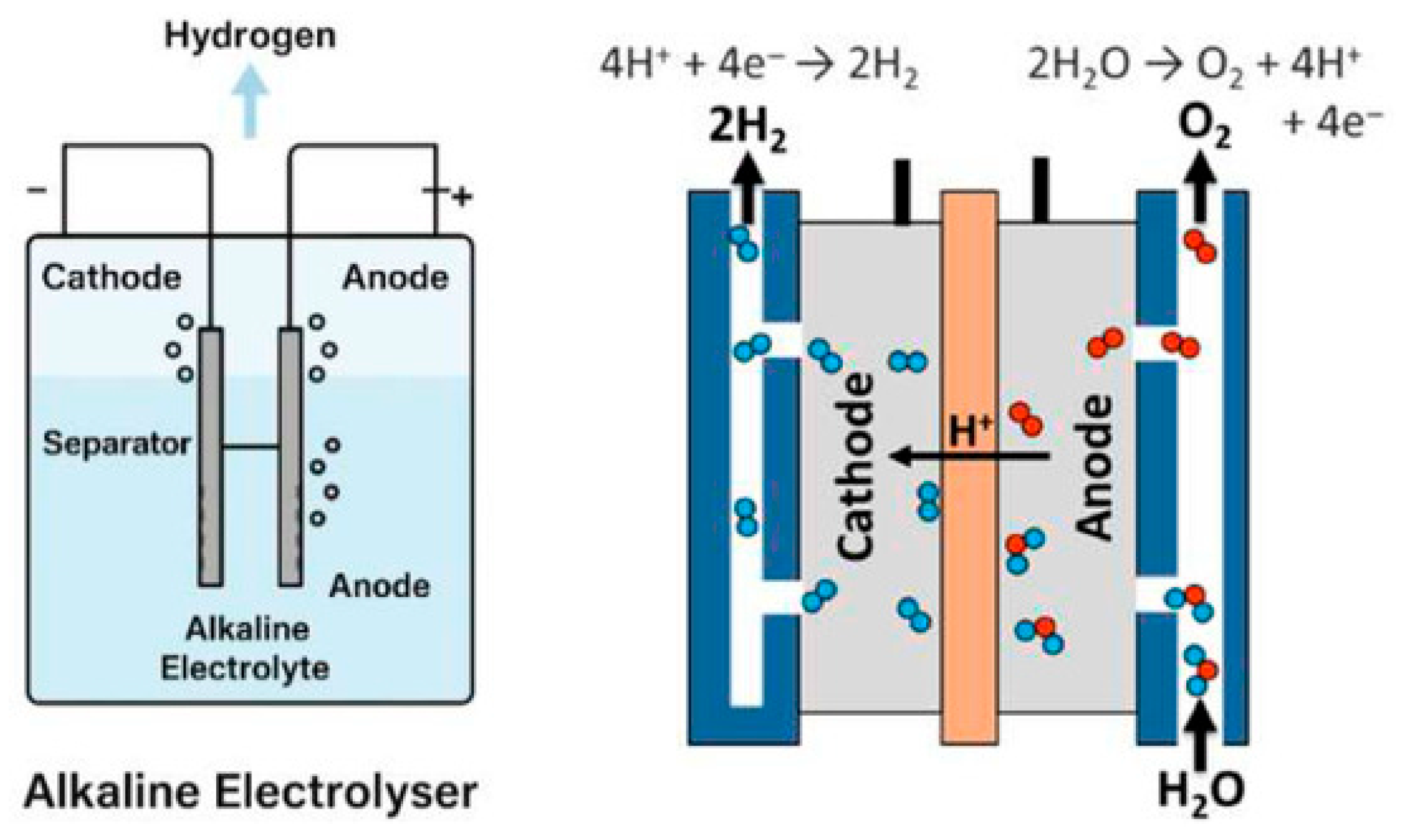
Alkaline Water Electrolyzers (AWEs): These typically use a concentrated KOH (or NaOH) aqueous electrolyte. The cathode is often a Ni-based alloy (e.g., Ni–Fe or Ni–Mo) for HER, and the anode is a nickel or cobalt oxide/hydroxide (e.g., NiOOH or Co3O4) for OER. Alkaline electrolyzers are technologically mature and utilize inexpensive materials (Ni) that are stable in alkaline media. However, they operate at modest current densities (e.g., ~0.2–0.5 A/cm2) and moderate efficiency (60–70%). They produce high-purity H2 but have somewhat lower throughput than other methods due to slower kinetics in alkaline conditions [5,21]. A schematic of the process and reactions is shown in Figure 1.
Proton Exchange Membrane (PEM) Electrolyzers: These use a solid polymer proton-conducting membrane (commonly Nafion) as the electrolyte. The HER cathode typically employs platinum or a Pt alloy on carbon, and the OER anode uses iridium oxide (IrO2) or ruthenium oxide (RuO2) on a conductive support. PEM electrolyzers achieve higher current densities (≥1–2 A/cm2) and efficiencies around 75–80%, due to fast proton transport and excellent catalyst activity. The trade-off is cost: the acidic environment necessitates expensive noble metal catalysts and corrosion-resistant cell hardware (e.g., titanium flow plates). Research is ongoing to reduce precious metal loading, for instance, by using novel catalyst supports or alloying iridium with cheaper elements. An example is the SrTi1−xIrxO3 perovskite catalyst, which achieved high OER activity with only one-third of the anode Ir content by optimally substituting Ir into the lattice (x ≈ 0.33) [5,23].
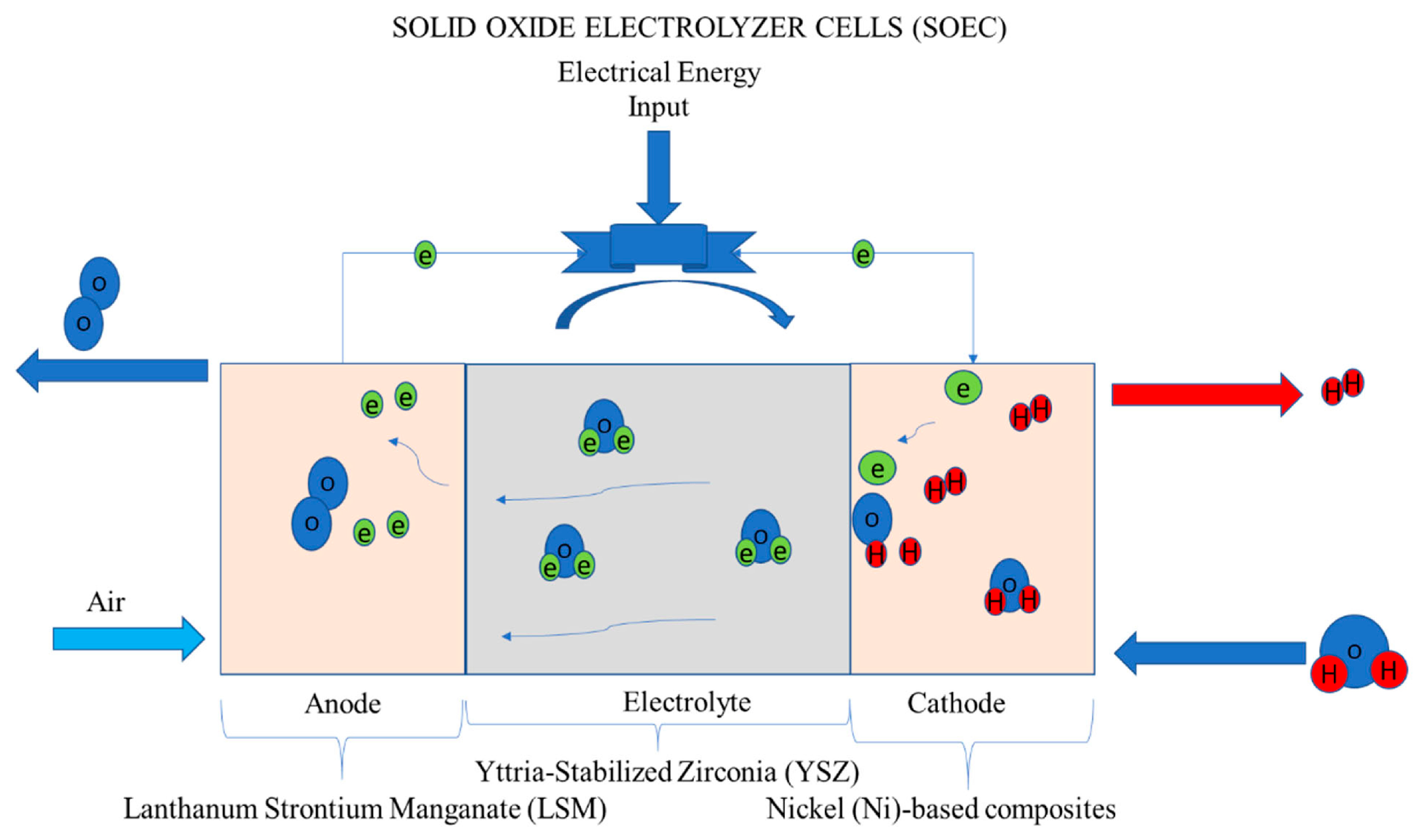
Solid Oxide Electrolyzer Cells (SOEC): These operate at high temperatures (typically 700–900 °C) using a solid ceramic (e.g., yttria-stabilized zirconia, YSZ) that conducts oxygen ions. The cathode (fuel electrode) is usually a cermet of Ni–YSZ, catalyzing steam reduction to H2, while the anode (oxygen electrode) is a perovskite oxide such as strontium-doped lanthanum manganite (LSM) for O2 evolution. Because a portion of the energy is supplied as heat, SOECs can reach very high electrical efficiency (85–90%) when integrated with thermal sources. However, the high operating temperatures pose material challenges and can cause faster degradation (e.g., due to thermal expansion mismatch). This method is currently in the demonstration stage, often using waste heat or nuclear heat to assist electrolysis [5,23]. A schematic of SOEC is shown in Figure 2.
Besides water electrolysis, hydrogen can also be extracted from hydrocarbons through thermochemical reforming processes. The dominant industrial route is Steam Methane Reforming (SMR), where methane reacts with steam over a Ni-based catalyst to produce H2 and CO (followed by water–gas shift to convert CO to CO2 and more H2). SMR is efficient and inexpensive, but emits CO2 unless coupled with carbon capture [25]. Other methods include Autothermal Reforming (ATR) (where partial combustion provides heat for reforming) and Biomass Gasification/Reforming, where renewable biomass is converted into a hydrogen-rich syngas. These “brown/gray” (fossil-based without CO2 capture), “blue” (fossil-based with CO2 capture), and “green” (renewable-based) hydrogen pathways are often distinguished by a color code in industry discussions [26].

2.2. Thermodynamics and Kinetics of Hydrogen Production

Hydrogen generation via water splitting is governed by fundamental thermodynamics and reaction kinetics. At standard conditions (25 °C, 1 bar), the theoretical minimum cell voltage required to split water is 1.23 V, as determined by the Gibbs free energy change of the reaction [27]. In practice, real electrolysis cells must operate at higher voltages to overcome kinetic barriers and internal losses. Another reference point is the thermoneutral voltage (~1.48 V at 25 °C), which accounts for the full enthalpy change (including the heat needed to keep the cell isothermal). If a cell runs below 1.48 V, it must absorb heat from its surroundings; above 1.48 V, it generates excess heat that must be removed by cooling [28,29].
The gap between the ideal 1.23 V and the actual operating voltage arises from overpotentials (overvoltages). Overpotentials are extra voltage required due to: (a) Activation overpotential—to drive the sluggish reaction kinetics at electrodes (e.g., breaking H–OH bonds in water); (b) Ohmic overpotential—to overcome resistances in the electrolyte, membrane, and electrodes; and (c) Mass transport overpotential—to account for limitations in reactant supply or product removal, such as accumulation of gas bubbles at the electrodes. These losses cause typical electrolyzers to operate in the range of ~1.8–2.2 V per cell under load, instead of the thermodynamic minimum. For example, a commercial alkaline electrolyzer might run at ~1.85 V to deliver a practical current density, the difference (~0.62 V above 1.23 V) being due to kinetic and resistive losses [28,30].
Understanding these losses is crucial for improving efficiency. One common analytical tool is Tafel analysis, which examines the relationship between overpotential and current density (typically plotted on a logarithmic current scale). The Tafel slope extracted from this plot gives insight into the reaction mechanism and the rate-determining step. A low Tafel slope means the reaction rate increases rapidly with added voltage (indicating good kinetics). However, Tafel analysis must be applied carefully: recent studies highlight that misinterpreting Tafel slopes is easy if mass transport or uncompensated resistance effects are present. It is recommended to complement Tafel plots with techniques like electrochemical impedance spectroscopy (to separate charge-transfer resistance and diffusion resistance) and rigorous product quantification, to accurately identify kinetic parameters [31,32].
Another significant kinetic factor is the formation of gas bubbles on electrode surfaces. During electrolysis, as H2 and O2 gases evolve, bubbles can cling to catalyst sites, effectively blocking those areas and increasing local resistance. This leads to higher overpotential and can limit achievable current densities. Engineers have observed that at high current, electrodes may become covered by gas, reducing the effective area for reaction. To mitigate this, electrodes are being designed with microscale and nanoscale features (e.g., hydrophobic coatings or geometric grooves) that encourage bubbles to detach and rise away quickly. For instance, hydrophobic layers or pyramid-textured surfaces can reduce bubble residence time and therefore lower mass transport overpotential [33,34].
In summary, thermodynamics provides the baseline energy requirement for splitting water, but it is the kinetics and transport phenomena that determine how close an actual system can approach that ideal. That is why catalyst improvements (to reduce activation overpotential), high-conductivity cell components (to reduce ohmic loss), and clever electrode designs (to alleviate diffusion limitations) are all crucial for pushing electrolyzer efficiency closer to the theoretical limits.

2.3. Performance Metrics: Activity, Selectivity, Stability, Efficiency

Evaluating catalysts and systems for hydrogen production involves several key metrics:
Activity: This reflects how readily a catalyst drives the desired reaction (HER or OER). In practice, activity is often gauged by the overpotential required to reach a certain current density (hydrogen production rate). For example, a catalyst that achieves 10 mA cm−2 H2 current at 100 mV overpotential is more active than one that needs 300 mV to reach the same current. Researchers commonly benchmark at current densities like 10 mA cm−2 or 100 mA cm−2 to compare catalysts. A lower overpotential at a given current indicates that the catalyst has better kinetics (i.e., more active sites or faster reaction steps) [35].
Selectivity: In water splitting, selectivity is typically expressed as the Faradaic Efficiency (FE), which is the fraction of electrical charge that ultimately produces the target product (H2 or O2). Ideally, FE is ~100%, meaning every electron results in hydrogen gas. In practice, side reactions or parasitic currents can lower FE. For instance, in acidic PEM electrolysis, some current may go into corrosion or mixed potentials, and in alkaline cells, impurities can cause side reactions. Careful measurement of the gas output is needed to determine FE. For example, comparing the measured volume of H2 to the theoretical volume from the passed charge. Ensuring near-100% FE usually involves using appropriate catalyst materials and operating conditions that minimize competing reactions, and properly accounting for any hydrogen crossover or leaks. Standard protocols call for calibration of gas collection and background corrections to obtain accurate FE values [36].
Stability: This indicates how well a catalyst or cell maintains its performance over time. A highly active catalyst is of limited use if it rapidly degrades. Stability is often reported as the percentage of initial activity retained after a certain operating period (e.g., “90% of initial current maintained after 100 h at 100 mA cm−2”). Researchers also perform accelerated stress tests (ASTs) to simulate long-term wear in a shorter time. For example, potential cycling (rapidly raising and lowering the voltage) can accelerate catalyst sintering or dissolution, and holding at high current can stress membranes and supports. Best practices for reporting stability include providing details of the AST protocol (temperature, electrolyte, cycling parameters) so results can be compared across studies. Stability is particularly critical for OER catalysts in harsh environments (like IrO2 in acidic PEM cells) and for non-noble catalysts that may corrode. Recent studies recommend advanced durability tests, such as square-wave potentiostatic holds or dynamic load profiles that mimic renewable power input, to evaluate catalyst resilience under realistic conditions. For example, a stability test might show that a certain Co–Fe oxide anode loses only 5% activity over 500 h, whereas an unmodified Co oxide loses 20% in the same period [37,38].
Efficiency: This is a system-level measure of how much energy input is converted into hydrogen’s chemical energy. It can be expressed in terms of cell voltage (relative to the thermodynamic minimum) or overall energy efficiency (accounting for electrical and thermal inputs). For instance, if an electrolyzer operates at 1.85 V per cell, where 1.23 V is ideal, the voltage efficiency is ~1.23/1.85 ≈ 66%. Efficiency can also be given as a “tank-to-gas” percentage using enthalpy values (which would rate that same cell around 80% efficient if including heat usage). When analyzing efficiency, it’s important to note the reference basis (Gibbs free energy vs. enthalpy) and operating conditions (higher temperatures can raise thermodynamic efficiency by allowing more thermal input). Agencies like the U.S. Department of Energy set targets for electrolyzer efficiency (for example, aiming for >75% LHV efficiency at a certain current density) and for durability (e.g., <10% performance degradation over 5 years). Reporting a system’s efficiency alongside these targets helps contextualize progress. For instance, a new AEM electrolyzer catalyst might be reported to achieve 72% efficiency at 500 mA cm−2 and maintain 95% of initial performance after 1000 h, moving closer to DOE’s benchmarks [5,39].
Overall, an optimal hydrogen-generation catalyst or system exhibits high activity and selectivity (fast hydrogen production with minimal side reactions), together with robust stability (minimal degradation over time) and high efficiency (low energy consumption per kg H2). Balancing these metrics is the central theme in hydrogen research, driving innovations in catalyst composition, electrode structure, and operational strategies to meet performance and durability targets.

3. Hydrogen Generation Methods and Relevant Catalysts

The major methods for hydrogen production include electrochemical water splitting, photocatalysis, and thermochemical reforming. Each method operates under different principles and conditions, requiring distinct catalysts and engineering approaches. Table 1 provides a summary of these methods, highlighting typical catalysts, efficiency ranges, operating temperatures, and key advantages and disadvantages.
Each method’s performance is intimately linked to its catalysts. Below, we discuss each in more detail:

3.1. Electrochemical Water Splitting

Electrochemical water splitting uses electrical energy to split water into hydrogen and oxygen. This category covers the alkaline, PEM, and solid oxide electrolyzers. To briefly recap with context from Table 1:
Alkaline Electrolysis: Uses Ni-based catalysts (e.g., Ni or Ni–Fe for HER, Ni–Fe or Ni–Co oxides for OER) in a liquid alkaline electrolyte. Efficiency is about 60–70% (HHV basis), and it operates at 60–90 °C. Its strengths are technological maturity and inexpensive components, but it runs at lower current density and requires careful gas separation in the KOH electrolyte [42].
PEM Electrolysis: Uses noble metal catalysts (Pt at the cathode, Ir/Ru oxides at the anode) and a solid polymer membrane. Efficiency is higher (~75–80%), with current densities up to 2 A/cm2, at operating temperatures below ~80 °C. Advantages include compact cell design, high-purity H2 output, and dynamic operation suited for intermittent power. The main disadvantages are the reliance on scarce noble metals and expensive perfluorosulfonic membranes, as well as water management (keeping the membrane humidified without flooding the cell) [42].
Solid Oxide Electrolysis: Uses ceramic catalysts (e.g., Ni–YSZ for the steam/H2 electrode, LSM for the O2 electrode) at 700–900 °C. It can reach very high efficiency (85–90%), especially if waste heat is utilized, but the high temperature causes thermal stress and sealing challenges. This method is advantageous when cheap high-temperature heat is available (for example, from industrial processes or high-temperature reactors) and when hydrogen output doesn’t need to be near ambient conditions [42].
One key research thrust in electrolysis is reducing catalyst costs, notably, finding alternatives to Ir for PEM electrolyzers. One notable advance reported is the use of a strontium titanate perovskite with partial iridium substitution, SrTi0.67Ir0.33O3, which maintained high OER activity with significantly lower Ir content. Another area is improving non-noble catalysts for electrolysis. For example, advanced Ni-based catalysts have been developed, as mentioned in Section 3.2, where structural modifications (like Ni–Mo alloying or Ni–Fe LDH nanostructures) have greatly improved performance in alkaline cells. These modifications address issues like surface oxidation and slow kinetics by creating more active sites and favorable local environments for the reactions [43].
Additionally, innovative methods are being explored to boost electrolysis efficiency. One such method is sonoelectrocatalysis, which applies ultrasonic waves during electrolysis. Ultrasound can improve mass transport by dislodging gas bubbles and agitating the electrolyte. In one study, sonoelectrocatalysis using ZnO, Cu2O, and graphene catalysts increased hydrogen production by 10–20% compared to conventional electrolysis. However, the overall efficiency fell slightly due to the energy consumed by ultrasound, and hydrogen purity reached only ~50% in that setup [44]. Graphene performed best among the tested catalysts under sonication, indicating the potential of combining nano-carbon catalysts with ultrasound to enhance HER kinetics. Future research on this hybrid approach will have to tackle scaling challenges (ensuring uniform ultrasound distribution in large cells), lowering the ultrasonic energy cost, and maintaining reactor material integrity under cavitation.
While catalysts and new techniques are critical, the reliable operation of electrolysis systems is equally important. Recent reliability studies have shown that electrolyzer systems can suffer failures such as gas leaks, electrode degradation, and even internal explosions if not properly managed. For instance, an unexpected power outage in a poorly designed cell allowed hydrogen and oxygen to mix and ignite, damaging the electrolyzer. To mitigate such risks, engineers are developing better system controls and protective measures. It has been suggested to maintain a reliability database of degradation modes, to rank critical components by failure risk, and to implement safety systems like robust gas purges or UPS backups to handle power interruptions. These measures, combined with improved catalysts, will ensure that advanced electrolyzer technologies can operate not only efficiently but also safely and continuously over long periods [45].

3.2. Photocatalysis

Photocatalytic water splitting uses solar energy and semiconductor catalysts to drive HER and OER simultaneously in a single device. Unlike electrolysis, which uses external electricity, photocatalysis relies on photons to excite electrons in a semiconductor, which then participate in water-splitting reactions. Key mechanisms by which plasmonic or semiconductor materials enhance photocatalysis include hot electron injection, light scattering, light concentration, and resonant energy transfer [39].
The main limitation of current photocatalytic systems is their low efficiency, largely because they can use only a small portion of the solar spectrum effectively (primarily the UV, which is ~4% of sunlight). Conventional photocatalysts like titanium dioxide (TiO2) have a wide band gap (~3.2 eV) and absorb only UV light. To extend the response into the visible range, researchers have incorporated plasmonic nanoparticles such as gold (Au) or silver (Ag) onto semiconductors [39]. These metals exhibit surface plasmon resonance under visible light, meaning they can absorb visible photons and generate energetic (“hot”) electrons. Those hot electrons can then transfer into the conduction band of an adjacent semiconductor (like TiO2), enhancing visible-light photocatalysis.
Another approach is designing Z-scheme photocatalysts, which mimic natural photosynthesis by using two different semiconductors that complement each other in light absorption. In a Z-scheme, one photocatalyst (with a higher conduction band) generates hydrogen and another (with a lower valence band) generates oxygen, with an electron bridge between them. This scheme helps maintain strong redox power for both half-reactions. A recent example is a hybrid CNO/MoS2/Ag system (carbon nano-onions decorated with flower-like MoS2 and dendritic Ag) that was shown to enhance charge separation and light absorption. In this system, Ag plasmonic particles harvest visible light and inject electrons into MoS2, while carbon nano-onions improve conductivity and stability, yielding significantly better HER performance and resistance to degradation [46].
Photocatalysis is still at an early stage compared to electrolysis. Present solar-to-hydrogen efficiencies are often only a few percent, far below electrolysis. To improve this, research focuses on developing new visible-light-responsive materials (e.g., tantalum nitride, organic polymer photocatalysts), improving charge separation (by adding co-catalysts like Pt or by forming built-in electric fields at junctions), and stabilizing the photocatalysts (since many can photocorrode under light). On the engineering side, large-scale photocatalysis might involve panels or slurry reactors under sunlight, requiring solutions for gas collection, catalyst recovery, and intermittency. While photocatalysis offers the appealing prospect of directly converting sunlight to hydrogen without an intermediate electrical step, it will need further breakthroughs in catalyst efficiency and stability to become competitive.

3.3. Thermochemical Reforming

Thermochemical reforming refers to high-temperature chemical processes that extract hydrogen from fuels or feedstocks, typically using catalysts and heat. The most prevalent example is Steam Methane Reforming (SMR), mentioned earlier, which dominates current hydrogen production but emits CO2. Here, we focus on alternative reforming approaches that align with sustainable energy goals, such as biomass reforming and novel chemical cycles.
Biomass Reforming: Renewable biomass (like agricultural waste or wood) can be converted to hydrogen through processes like pyrolysis and gasification, followed by reforming. In fast pyrolysis, biomass is rapidly heated in the absence of oxygen, producing a mix of bio-oil, syngas, and char. The syngas and vapor can then undergo steam reforming in the presence of a catalyst (often Ni-based, similar to SMR) to produce H2. One challenge in biomass reforming is the presence of impurities (tar, sulfur, etc.) in the gas, which can foul catalysts. A strategy to address this is Sorption Enhanced Steam Reforming (SESR): adding a CO2 sorbent (like dolomite or CaO) in the reformer to capture CO2 in situ, which both drives the equilibrium toward more H2 and helps keep the reforming catalyst sites cleaner. Studies have shown that using dolomite as a CO2 absorbent in a biomass reformer increased hydrogen yield and produced a higher-purity H2 stream, simplifying downstream separation. The combined processes of pyrolysis + SESR can achieve moderate efficiency in practice (as indicated in Table 1, around 65–75% efficiency for biomass reforming systems) [14].
Aluminum-Water Reaction: An intriguing emerging thermochemical approach is using aluminum metal to generate hydrogen from water. Normally, aluminum is protected by a stable oxide layer and does not react with water. However, if this oxide is removed or disrupted (for example, by alloying aluminum with gallium, indium, or other metals to form an active composite), aluminum will react exothermically with water to produce hydrogen and aluminum oxide. Recent research demonstrates that sintering aluminum with small amounts of gallium-based liquid metal can create a composite that spontaneously generates H2 upon contact with water at room temperature. This method yields hydrogen on-demand without needing an external heat source, producing only aluminum hydroxide as a byproduct. The challenge is that the gallium (used to disrupt the Al2O3 layer) is expensive, and recycling the aluminum oxide back to aluminum is energy-intensive (essentially shifting the energy cost upstream to aluminum production). While not yet an economical large-scale hydrogen source, this concept is being explored for special cases like hydrogen generation in remote areas or portable hydrogen generators, where simplicity and on-demand production are valued [47].
In summary, thermochemical methods remain relevant especially for utilizing renewable fuels (like biomass) or industrial byproducts to produce hydrogen. Catalysts in these systems are often similar to those in traditional reforming (Ni-based for steam reforming, specialty catalysts for handling tar or ammonia in biomass gas), but additional innovations like CO2 sorbents or novel reactant activation (as in the aluminum example) are employed to improve efficiency and sustainability. Integrating these processes with carbon capture and using renewable process heat can turn them into low-carbon “blue” or “green” hydrogen pathways. For instance, a biomass gasifier with SESR effectively produces carbon-neutral hydrogen because the carbon in biomass was originally absorbed from the atmosphere, and any CO2 can be captured in process. Continued research in catalysts that resist fouling (e.g., catalysts with engineered surfaces to avoid tar deposition) and in process integration (like using solar concentrators to provide reforming heat) could further enhance the viability of thermochemical hydrogen production as part of a diversified hydrogen supply portfolio.

4. Types of Catalytic Materials

Catalytic materials for hydrogen generation span a broad range of metallic and non-metallic systems. They can be grouped into five classes:
  • Noble-metal catalysts (e.g., Pt, Pd, Ru, Ir, Rh);
  • Transition-metal catalysts (base metals like Ni, Co, Fe, Mo, and their alloys);
  • Metal compounds (oxides, sulfides, nitrides, phosphides, etc.);
  • Carbon-based catalysts (including graphene, carbon nanotubes, doped carbons, MXenes);
  • Hybrid and composite catalysts (nanostructures or multi-component systems that synergistically combine different materials).
Each category involves trade-offs among performance, cost, and stability, and research efforts aim to maximize catalytic activity while minimizing reliance on scarce elements.

4.1. Noble Metal Catalysts

Pt, Ru, Ir, Pd-based Catalysts: Noble metals such as platinum, ruthenium, iridium, palladium, and rhodium are widely considered benchmark catalysts for both HER and HOR (hydrogen oxidation reaction in fuel cells) [48]. Their superior performance arises from an optimal balance in hydrogen binding energy (neither too weak nor too strong), as well as excellent corrosion resistance under electrochemical conditions. For example, platinum remains the most active HER catalyst in acidic media, requiring very low overpotential and exhibiting outstanding stability [49]. Similarly, IrO2 and RuO2 are among the most active OER catalysts in water electrolysis, and are used in state-of-the-art PEM electrolyzers despite their cost [50].
Advantages and Limitations: Despite their exceptional catalytic properties, noble-metal catalysts face critical drawbacks. First, their high cost and scarcity (Pt, Ir, etc.) limit scalability. Large-scale deployment of electrolyzers or fuel cells using these metals would be prohibitively expensive and constrained by limited supply. Second, they can be poisoned by impurities. For instance, trace CO or sulfur compounds strongly adsorb on Pt, reducing their active surface area and performance (this is a particular concern for fuel cells running on reformed hydrogen). Third, under prolonged operation at high potentials or temperatures, noble metal nanoparticles can sinter or dissolve, leading to loss of electrochemically active surface area. For example, Pt catalysts in PEM fuel cells can undergo Ostwald ripening and agglomeration, and IrO2 in a PEM electrolyzer can dissolve slowly into the acidic electrolyte, both causing efficiency decay over time. Table 2 summarizes these disadvantages and their impact on catalyst performance.
To alleviate these issues, researchers have developed nanostructured and alloyed noble metal catalysts that use less precious metal while maintaining high activity. For instance, forming Pt-based alloys (like Pt–Ni, Pt–Co) can strain the Pt lattice and modify its d-band electronic structure, yielding higher intrinsic activity for ORR/HER and improved durability, meaning that less Pt can be used for the same performance [53]. Core–shell architectures are another strategy, where a thin shell of noble metal is coated on a core of cheaper material (e.g., Pt monolayer on a Pd or Ni nanoparticle). This achieves high surface catalytic activity with a fraction of the noble metal content. Despite these advances, noble metals remain the reference standard for catalyst performance. New materials are often benchmarked against Pt or Ir-based catalysts to gauge their efficacy. Reducing dependence on noble metals is a major motivation behind the exploration of the catalyst classes discussed next.

4.2. Transition Metal Catalysts

Ni, Co, Fe, Mo-based Systems: Base metals like nickel, cobalt, iron, and molybdenum offer earth-abundant, low-cost alternatives to noble metals for hydrogen catalysis [54]. Their catalytic behavior is strongly influenced by their electronic structure (especially the d-band center), which determines how strongly they bind hydrogen and reaction intermediates.
Nickel-based catalysts are extensively used in alkaline electrolyzers because Ni provides good HER activity in basic media and is stable (forming protective NiO/Ni(OH)2 layers). Cobalt and iron oxides/hydroxides are effective OER catalysts in alkaline solutions, often employed in rechargeable battery and electrolyzer electrodes, due to their multiple oxidation states that facilitate oxygen release [55]. Molybdenum, often as molybdenum disulfide (MoS2) or molybdenum phosphides, has attracted attention in both HER and CO2 reduction because it can mimic some of the electronic properties of noble metals at a much lower cost [56].
Bimetallic and Alloy Catalysts: Combining transition metals can create synergistic effects where one element modifies the electronic or structural properties of another. For instance, Ni–Mo alloys show markedly improved HER performance in alkaline media compared to pure Ni, because Mo can help adsorb hydrogen and also resist surface poisoning. Similarly, Ni–Fe layered double hydroxides (LDHs) are among the best OER catalysts in alkaline electrolyte: Ni provides a conductive matrix and active sites, while Fe incorporation (even a few percent) drastically enhances OER activity through electronic and structural tuning. Another example is Co–Fe oxides for OER, where Co provides conductivity, and Fe boosts the OER kinetics. These bimetallic combinations can rival noble metal performance under certain conditions, as seen by NiFe LDH’s ability to approach IrO2’s OER activity in alkaline water splitting with far lower cost [57].
Despite their promise, transition-metal catalysts have their own challenges. In acidic environments (like PEM cells), base metals tend to dissolve. For instance, a Ni or Co catalyst would corrode rapidly at low pH, which is why noble metals are still required for PEM systems. Additionally, under continuous operation, transition metal catalysts can undergo oxidation (forming insulating oxides/hydroxides in alkaline media) or other phase changes that reduce their activity [58]. Strategies to improve their durability include applying protective coatings (e.g., carbon or TiN layers on Ni to prevent direct acid attack) and using composite structures so that base metals are only exposed to less aggressive conditions (like embedding Ni particles in an ionomer that moderates the local pH in a PEM anode). Overall, transition metals represent a key direction in catalyst research aimed at reducing cost. When properly engineered (through alloying, nanostructuring, and hybridization), they have demonstrated efficiencies approaching those of noble metals in laboratory tests.

4.3. Metal Oxides, Sulfides, and Nitrides

Moving beyond pure elements, many binary or ternary compounds of metals offer catalytic properties with greater structural and chemical flexibility. These include oxides, sulfides, nitrides, phosphides, carbides, and more.
Metal Oxides: Transition metal oxides (e.g., NiO, Co3O4, Fe2O3) and complex oxides (like perovskites and spinels) are widely studied for OER catalysis due to their stability in oxidative environments. Perovskites of the form ABO3 (such as LaNiO3 or SrCoO3) allow substitution at the A or B sites, tuning catalytic behavior. They can form oxygen vacancies (missing O atoms in the lattice), which increase electrical conductivity and create reactive sites for OER [59,60]. For example, adding strontium to LaCoO3 (forming La1−xSrxCoO3) enhances OER activity by improving conductivity and altering Co’s oxidation state. Spinel oxides (AB2O4), like NiCo2O4, also exhibit high bifunctional activity; in NiCo2O4 the Ni and Co can cycle between oxidation states during OER, aiding the reaction [61].
Metal Sulfides: Transition metal sulfides (notably MoS2 and WS2) have a layered structure analogous to graphene, with strong in-plane bonds and weak van der Waals bonds between layers [58]. In MoS2, the basal planes are catalytically inert for HER, but the edge sites (where Mo and S atoms are under-coordinated) are active for HER. This means that engineering MoS2 to have more exposed edges (e.g., via making nanosheets or introducing defects) dramatically boosts its HER performance. 1T-phase MoS2 (a metallic phase) also shows improved HER activity compared to the semiconducting 2H-phase. Researchers create MoS2-based heterostructures, like MoS2 on graphene, to improve its conductivity and utilization of active sites. Cobalt sulfide (CoS2) and nickel sulfide (Ni3S2) are also active HER catalysts in alkaline media, often used on foam electrodes for a large surface area [59].
Metal Nitrides and Phosphides: Transition metal nitrides (e.g., Mo2N, VN) and metal phosphides (e.g., Ni2P, CoP, FeP) combine metallic-like conductivity with catalytic surfaces that can facilitate hydrogen reactions. For instance, nickel phosphide (Ni2P) is highly active for HER in alkaline solutions, benefiting from a unique Ni–P bonding environment that adsorbs hydrogen intermediates optimally [60]. These materials are often bulk stable and resistant to poisoning. Many nitrides and phosphides can also serve as robust supports or co-catalysts. For example, molybdenum nitrides have been used as supports for Pt in fuel cells, improving stability.
Because many metal compounds (especially oxides) have lower intrinsic conductivity than pure metals, a common strategy is to couple them with conductive networks. For example, OER catalysts like NiFe LDH are often deposited on carbon nanotubes or graphene to provide an electron highway, and HER catalysts like MoS2 are grown on carbon cloth or coupled with MXene nanosheets to facilitate charge transfer. In addition, creating composite electrodes (e.g., mixing an oxide with a metal or with a carbon binder) can improve mechanical stability and prevent catalyst particles from sintering or dissolving by physically separating them and maintaining distribution [61].
Role in HER and OER: Metal oxides, sulfides, and nitrides have become key players in improving water-splitting efficiency by targeting specific half-reactions. For HER, materials like MoS2, WS2, and Ni2P offer near-optimal hydrogen adsorption. They bind H* strongly enough to catalyze H–H bond formation, but not so strongly that the sites get blocked [54,62]. Through phase control (e.g., 1T vs. 2H MoS2) and nanostructuring (to expose edge sites or introduce porosity), researchers have significantly improved HER currents from these materials. Some nitride catalysts like VN and Mo2N are also effective HER catalysts, particularly in alkaline environments, because they maintain high conductivity and can form surface hydrides readily [54,56].
For OER, oxides and hydroxides are predominant. Spinel and perovskite oxides are effective because their multivalent metal cations (like Co3+/Co4+ or Mn3+/Mn4+) can facilitate the complex four-electron transfer of OER [53]. Creating oxygen vacancies (defects where O is missing) in these oxides has been shown to enhance OER activity by increasing the number of reactive sites and improving electronic conductivity [51]. For example, oxygen-deficient strontium cobaltite (SrCoO3−x) has higher OER activity than the stoichiometric compound because the vacancies help form intermediate OOH* species more easily. Additionally, some transition metal phosphates and borates (e.g., CoPi, a cobalt phosphate) work as OER catalysts in neutral/near-neutral conditions, which is useful for specialized electrolysis systems like solar-driven cells
In summary, metal compounds broaden the palette of catalyst options beyond pure metals. They often provide unique structures that can be optimized (via doping, defect creation, or phase control) for improved HER/OER performance, and they tend to be more abundant than noble metals. The challenge is ensuring they are conductive and stable under operating conditions, which is why hybrid structures (e.g., an active compound on conductive support) are frequently employed.

4.4. Carbon-Based Catalysts

Carbon-based materials serve both as active catalysts (especially when modified) and as critical conductive supports in hydrogen-generation electrodes. They are lightweight, chemically tunable, and highly conductive, making them indispensable in modern catalyst layer design.
Graphene and Doped Carbons: Pristine graphene is an excellent electrical conductor, but is catalytically inert because of its symmetric sp2 carbon network. By introducing heteroatom dopants such as nitrogen (N), sulfur (S), phosphorus (P), or boron (B) into the carbon lattice, the electronic structure can be perturbed to create reactive sites [60,61]. For example, nitrogen-doped graphene contains pyridinic and quaternary N sites that can adsorb hydrogen or hydroxyl intermediates, enabling it to catalyze HER or even ORR to some extent. Graphitic carbon nitride (g-C3N4), a carbon-nitrogen polymer, has also been studied as a metal-free photocatalyst for water splitting due to its appropriate bandgap and surface chemistry. These doped carbons are stable and resist acidic corrosion better than many metals, though their catalytic activity is generally lower than that of metal catalysts.
Carbon Nanotubes (CNTs): CNTs offer a combination of high surface area, excellent conductivity, and mechanical robustness. They are widely used as supports for dispersing catalyst nanoparticles. For instance, Pt or Ni particles deposited on CNTs tend to have enhanced durability and utilization because the CNTs facilitate electron transport and prevent particles from aggregating [61]. Functionalizing CNT surfaces (by adding carboxyl, hydroxyl, or dopant atoms) can anchor metal ions or clusters strongly, creating catalytic active sites (e.g., Co–N–C sites on nitrogen-doped CNTs for ORR). In alkaline HER, electrodes made of Ni–Mo on CNT scaffolds have shown higher current and better stability compared to those on planar metal foils, underscoring the benefit of a conductive 3D carbon network.
MXenes and Other 2D Carbides/Nitrides: MXenes are a family of 2D transition metal carbides/nitrides (e.g., Ti3C2Tx, Mo2CTx, where Tx represents surface terminations like –OH or –O) that behave like conductive, hydrophilic sheets. They have been investigated as supports and co-catalysts for HER/OER because they combine metallic conductivity with functional surface groups that can participate in catalysis. For instance, Ti3C2 MXene decorated with Pt nanoparticles yields a hybrid catalyst with exceptional HER performance, where the MXene support accelerates electron transfer and provides some catalytic contribution on its terminated surface, allowing a reduction in noble metal content. MXenes are also being explored as catalysts themselves; some studies report that defect-rich or terminated MXenes can catalyze HER with decent efficiency, especially in acidic media, and serve as durable supports in harsh conditions where carbon might oxidize.
Carbon-based catalysts and supports face challenges. Carbon can corrode (burn) at high anodic potentials in acidic media (relevant for PEM OER, where carbon supports must be avoided or protected), and mechanical delamination can occur in certain conditions. Nonetheless, their advantages (lightweight, flexible, conductive) make them vital for practical devices. In many modern PEM fuel cells and electrolyzers, the catalyst layer is composed of metal or metal oxide particles embedded in a carbon–ionomer matrix: the carbon ensures conductivity and uniform dispersion, while the ionomer ensures ionic connectivity, and the catalyst does the chemical work. Improving the stability of carbon in these environments (through graphitization, doping, or replacement with conductive ceramics like Ti4O7) is an active area of research, as noted for HT-PEM fuel cells, where corrosion-resistant carbon supports are being developed [61].

4.5. Hybrid and Composite Catalysts

To overcome the limitations of single-component systems, hybrid catalysts combine multiple materials, aiming for synergistic effects that enhance overall performance. These hybrids can take various forms, including core–shell structures, heterojunctions, and supported catalysts.
Nanostructured Core–Shell and Heterostructures: In core–shell catalysts, a thin shell of an active material is coated on a stable core. For example, a Ni or Cu nanoparticle core can be coated with a few atomic layers of Pt or with a MoS2 shell. The core provides mechanical support and often improved electron conductivity, while the shell provides the catalytic surface. This architecture greatly reduces noble metal usage (since the noble metal is only a shell) while maintaining high activity [53]. A specific case is a Cu@Pt core–shell nanoparticle for HER. Cu is cheap and conductive, and a one-monolayer Pt shell still exhibits near-Pt-like HER activity with dramatically lower Pt content. Heterostructures, where two different catalysts are intimately interfaced (but not one fully enclosing the other), are also common. An example is a MoS2/graphene hybrid where MoS2 provides active HER sites, and graphene ensures excellent conductivity and flexibility. Such heterostructures can facilitate interfacial charge transfer—for instance, photoexcited electrons in a semiconductor can transfer to a metal co-catalyst at a junction more efficiently, boosting photocatalytic HER [59].
Supported Catalysts and Synergistic Designs: Most practical catalysts in electrolyzers and fuel cells are, in fact, supported catalysts—fine particles of the active catalyst are dispersed on a high-surface-area support. The support is typically electrically conductive and chemically stable (common supports include carbon blacks, graphite felt, titanium fibers, and conductive ceramics). By supporting catalysts on a structured substrate (like Ni foam, carbon cloth, or metal mesh), one can improve mass transport (the porous support allows gas and liquid flow) and distribute the catalyst to prevent clumping. Supports also absorb mechanical stress and can inhibit sintering, e.g., IrO2 nanoparticles on an antimony-doped tin oxide support show much better stability than unsupported IrO2 in PEM OER, because the support maintains separation of particles and provides an oxide framework that is itself corrosion-resistant. Another aspect of composite design is creating multi-functional interfaces. For instance, a catalyst layer might combine a metal for HER and an oxide for OER, forming a bifunctional electrode that can catalyze both half-reactions in an alkaline electrolyzer. Recently, researchers achieved a bifunctional catalyst by embedding NiMo alloy nanoparticles in a NiFe LDH matrix, resulting in an electrode that performs HER on the alloy sites and OER on the LDH sites, simplifying the system [61].
In all these cases, the goal is to harness the synergy between components: one material may provide high activity, another ensures conductivity or stability, and together they outperform either alone. Hybrid catalysts are particularly important for emerging technologies like photocatalytic water splitting, where often a light-absorbing semiconductor is combined with a co-catalyst (like loading Pt on TiO2 or MoS2 on CdS) to drastically improve the reaction efficiency. Another area is membrane electrode assemblies (MEAs) in fuel cells/electrolyzers, which are essentially composite catalysts at the device scale, integrating catalyst, support, ionomer, and gas diffusion layers. Advanced MEAs use gradient compositions (more hydrophilic near the membrane, more hydrophobic near the gas side) to manage water, or incorporate reinforcing meshes to improve mechanical resilience
In summary, hybrid and composite catalysts represent an advanced strategy to push performance beyond the limits of single materials. By designing at the nanoscale and mesoscale, engineers can create catalytic interfaces that leverage the strengths of each component (e.g., high active-site density, fast electron conductivity, corrosion resistance, etc.) and mitigate their weaknesses. These systems are increasingly prevalent in the latest hydrogen generation devices, as evidenced by catalyst layers containing multiple phases (metal, oxide, carbon, polymer) that work in concert.

4.6. Comparison of Catalyst Technologies

Catalytic materials can have extremely large activity ranges. This range is influenced by many factors, including but not limited to temperature, electrolyte, current, and age. The extremely low overpotential and Tafel slope of noble metals make them very desirable from a performance standard. This has led to them becoming a standard reference when developing new catalytic materials. The range of activity values of the different catalytic materials is presented in Table 3.

5. Mechanical and Structural Considerations

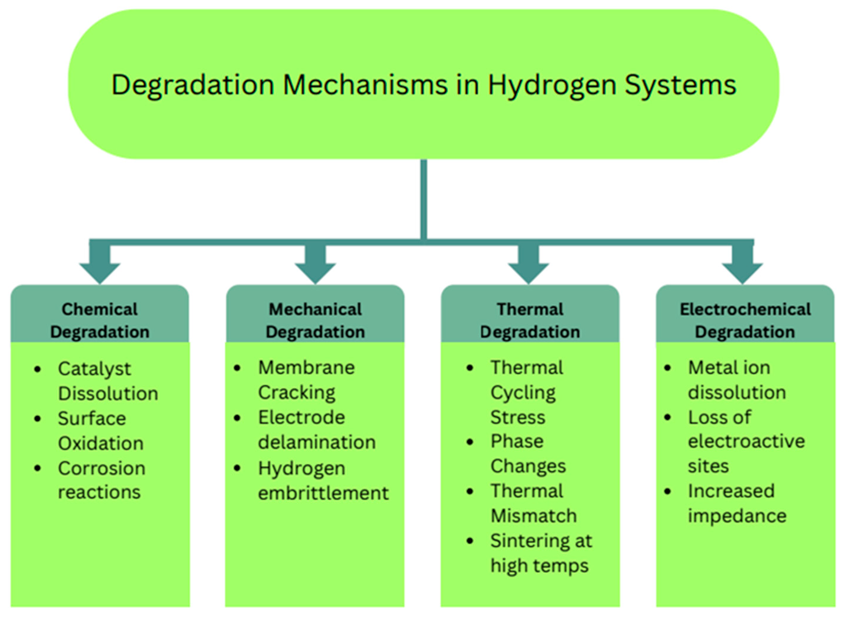
Despite advances in catalysts and processes, hydrogen generation systems face practical engineering challenges related to mechanical integrity, materials compatibility, and long-term durability. Electrolysis and fuel cell systems operate under conditions (temperature, pressure, electrical load cycling, corrosive environments) that can induce mechanical stresses and chemical degradation in membranes, electrodes, current collectors, and other components. Recognizing and mitigating these degradation mechanisms is essential for reliable and safe operation. Figure 3 schematically outlines major degradation pathways in water electrolyzers and fuel cells, including catalyst particle growth, membrane thinning, interfacial delamination, and bipolar plate corrosion.

5.1. Durability and Stability Under Operating Conditions

The primary catalysts used in water electrolysis (especially noble metals like Pt and Ir) are susceptible to gradual performance loss due to structural and compositional changes over time. For example, platinum nanoparticles can agglomerate or dissolve during extended operation, reducing the electrochemically active surface area and thus the hydrogen production rate. Iridium oxide anodes in PEM electrolyzers can undergo oxidation to iridate species or simply deplete via dissolution into the acidic electrolyte, leading to higher cell voltage over time [12]. Because noble metals are expensive and scarce, their degradation is a serious concern. A loss of catalyst means not only decreased performance but also a higher cost per unit of hydrogen produced. The performance degradation rate and life expectancy of different electrolyzer types are displayed in Table 4.
To extend catalyst life, researchers are experimenting with more robust alternatives and support structures. For instance, molybdenum disulfide (MoS2) has been studied as a non-noble HER catalyst that could partially replace platinum. MoS2 in its 1T metallic phase has better conductivity and catalytic activity than the 2H phase, but maintaining the active phase and preventing oxidation in the long term is challenging [67]. Even when new catalysts show high initial activity, ensuring they remain stable under continuous operation is critical.
Operating conditions themselves can accelerate degradation. Temperature fluctuations and load cycling (turning the electrolyzer on/off or varying its load with intermittent renewable power) impose thermal and mechanical stresses on components. A sudden rise in current density can generate local hot spots and high gas evolution rates, which may create mechanical forces on the electrode. Conversely, cooling or idle periods can lead to contraction and the formation of microcracks [12]. One mitigation strategy is to incorporate reinforcement materials into membranes and electrodes. For example, reinforcing a Nafion membrane with an expanded PTFE mesh greatly improved its dimensional stability and resistance to swelling/shrinking stresses, which in turn helped maintain the catalyst layer’s integrity over cycling. Similarly, adding ceramic fibers to an alkaline electrolyzer’s separator can prevent creep and maintain electrode compression over time.
Another approach to improve catalyst durability is to form hybrid catalysts with more stable matrices. For instance, alloying platinum with more corrosion-resistant metals (like gold) can reduce its dissolution rate, and anchoring noble metal nanoparticles on oxide supports (such as antimony-doped tin oxide or titanium suboxides) can physically prevent particle migration and shield them from direct exposure to the harsh environment [12]. Studies have shown that a titanium oxide-supported Ir catalyst had a slower degradation rate than unsupported Ir black under the same OER conditions, due to a strong metal–support interaction that inhibits Ir dissolution.
To evaluate and compare durability under realistic conditions, accelerated stress tests (ASTs) are used. One comprehensive study subjected PEM water electrolyzer MEAs to different stress profiles: constant current, square-wave cycling, and a simulated solar PV power profile. They found that dynamic load profiles (like the PV simulation, which had fluctuating power input) caused the fastest performance decay. Catalyst corrosion rates and titanium oxidation (in the porous transport layer) were higher under these variable conditions than under steady load. Constant high current caused a gradual voltage to increase mainly due to catalyst and membrane heating and potential accelerated aging, while square-wave on/off cycling induced mechanical fatigue in the catalyst layer and membrane. These results underscore that both electrochemical and mechanical stresses contribute to long-term degradation [70]. The lesson is that improving durability may require not just better materials but also smarter operation and controls—for example, avoiding extremely rapid load changes, or using hybrid storage (battery buffering) to shield the electrolyzer from full renewable intermittency.
In summary, ensuring durability involves a multi-faceted approach: developing catalysts that resist corrosion and coarsening, reinforcing membranes and electrodes to handle thermal/mechanical stress, and designing system controls that minimize unnecessary stress. By doing so, next-generation electrolyzers can achieve longer lifetimes (targeting >80,000 h of operation) and thereby lower the effective cost of hydrogen.

5.2. Mechanical Degradation in Electrodes and Catalyst Layers

The physical structure of the electrode and catalyst layer is crucial for sustained performance. Repeated thermal and hydration cycles can cause mechanical degradation such as cracking of catalyst layers, delamination between layers, and pinhole formation in membranes [71]. For instance, polymer electrolyte membranes (PEMs) like Nafion expand when hydrated and shrink upon drying. This cyclical strain can induce micro-cracks or even macro-scale tears over time, especially if the membrane is not reinforced. Similarly, catalyst layers (often composite films of catalyst + ionomer on the membrane) can separate (delaminate) from the membrane or develop cracks through their thickness due to differential expansion or gas bubble pressure.
Hydrogen itself can contribute to mechanical issues in certain materials. Hydrogen embrittlement is a well-known phenomenon where metals (especially high-strength steels and some polymers) become brittle and crack in the presence of hydrogen. Although embrittlement is more of a concern in storage tanks and pipelines than inside electrolyzers, it is relevant for any metal components exposed to high-pressure hydrogen. For example, studies on polyethylene exposed to high-pressure H2 (up to 5–10 MPa) showed significant reductions in tensile strength and ductility, along with blistering from hydrogen gas within the polymer [68]. This suggests that careful material selection or protective coatings are needed for any plastic components in contact with pressurized hydrogen gas.
Catalyst layers in PEM systems can degrade via particle coarsening and detachment. In one AST study of a PEM electrolyzer MEA, post-test analysis revealed extensive microstructural damage: cracks in the iridium oxide anode layer, loss of Ir due to dissolution, and fluoride release from the degraded Nafion membrane. The porous titanium flow field also showed signs of corrosion and passive oxide formation [70]. These observations indicate that mechanical integrity is intertwined with chemical stability. Cracks and delamination can accelerate chemical attack by exposing new surfaces, and corrosion can weaken structural support, making cracking more likely.
One specific study identified failure modes in Catalyst Coated Membranes (CCMs), which are integral to PEM fuel cells and electrolyzers. It found that high potentials and repeated start-stop cycles led to loss of contact between the catalyst layer and membrane (delamination), generation of pinholes in the membrane facilitating H2/O2 crossover, and catalyst particle detachment and agglomeration [72]. Poor membrane–catalyst adhesion was a particular issue, as it causes local current hotspots and exacerbates degradation. The recommended solution is improving fabrication method. For example, decal transfer methods that yield more uniform catalyst layers and better interfacial bonding, or adding short polymer chains that graft the catalyst layer to the membrane [72].
To manage mechanical degradation, engineers implement several strategies: (1) Reinforcing membranes (as mentioned, with PTFE or other meshes) to limit expansion and crack propagation. (2) Using resilient binders in catalyst layers (for instance, incorporating thermoplastic elastomers with the ionomer to give the layer some flexibility). (3) Designing cell hardware with compliant elements, like spring washers or gaskets that maintain uniform pressure on the cell as components expand/contract, so that the catalyst layers remain in good contact with the membrane and diffusion layers. (4) Ensuring effective water management: fully humidified membranes are less prone to mechanical dehydration stress, but over-saturation can cause flooding and mechanical stress from bubble pressure. Thus, proper hydration control avoids both membrane drying and extreme gas bubble buildup [72].
In summary, mechanical degradation can significantly reduce the lifespan of hydrogen generation systems if unaddressed. Through better materials (reinforced membranes, robust supports), careful assembly (secure catalyst–membrane adhesion), and operational safeguards (avoidance of abrupt thermal or load changes when possible), the structural integrity of these systems can be preserved, thereby sustaining efficiency and preventing failures like gas leaks or cell ruptures.

5.3. Thermal/Chemical Compatibility with Reactors and Fuel Cells

All components of a hydrogen generation or utilization system must be compatible with the thermal and chemical environment to ensure longevity. This includes membranes, catalysts, bipolar plates, sealants, and structural supports, each of which must tolerate the operating temperature and chemical conditions without significant degradation.
One example is the Solid Oxide Electrolysis Cell (SOEC). It operates at 600–900 °C, which puts stringent requirements on material thermal stability and matching of thermal expansion coefficients. The ceramic electrolyte (often YSZ) and the electrodes must expand and contract similarly with temperature to avoid cracking. However, many SOEC designs borrow materials from Solid Oxide Fuel Cells, and under electrolysis mode (which has a different polarization and gas environment), some materials degrade faster. For instance, conventional SOFC anodes (Ni–YSZ) can experience accelerated coarsening and redox cycling damage in the oscillating conditions of an SOEC fed intermittently with steam. To improve compatibility, new electrode materials are being developed specifically for SOEC duty. For example, replacing Ni–YSZ with ceria-based composites that have better redox stability, or introducing alternative cell architectures that operate at slightly lower temperatures (~550 °C) to reduce thermal stress. Additionally, lowering the operating temperature of SOECs (even by 100–150 °C) significantly eases material challenges and extends life, at some cost to efficiency. Research suggests that moving from 800 °C to 650 °C operation can dramatically slow the degradation of seals and interconnect coatings, making the system more durable (though catalysts must be even more active to compensate for slower kinetics at lower T) [73].
In contrast, consider High-Temperature PEM Fuel Cells (HT-PEMFCs), which run at 120–200 °C using phosphoric-acid-doped PBI membranes. These elevated temperatures allow PA-PBI fuel cells to tolerate CO in hydrogen and simplify cooling, but they introduce chemical compatibility issues. Hot, concentrated phosphoric acid is highly corrosive. Standard carbon supports can corrode (oxidize to CO2) in such conditions, and the PBI polymer can degrade over time, losing acid and conductivity. Developers have found that using more graphitic carbons (which oxidize much more slowly than amorphous carbons) or even replacing some carbon with conductive metal oxides (like Ti4O7 Magnéli phase, which is a conductive ceramic) significantly improves stability in HT-PEMFC electrodes. One study showed that a hybrid support containing Ti4O7 and graphitized carbon had an order of magnitude lower corrosion rate than conventional carbon black in 180 °C phosphoric acid, thereby extending catalyst life and maintaining performance [74]. On the membrane side, new acid-ionomer blends or cross-linked PBI materials are being explored to reduce acid loss and chemical degradation. Ensuring material compatibility in these systems might involve applying protective coatings to bipolar plates (e.g., gold or TiN coatings on steel plates to prevent acid attack and hydrogen embrittlement of the metal) and using acid-resistant gaskets and seals (like PTFE or graphite seals instead of rubber in a hot acid environment).
Ultimately, both the SOEC and HT-PEMFC examples illustrate that materials selection and engineering are critical to system longevity. Thermal compatibility requires matching expansion rates and sometimes limiting temperature gradients or cycling frequency. Chemical compatibility demands using materials that can resist reactive species (like O2, H+, OH, or H2) at the given temperature. Advances in electrode materials, such as robust mixed ion-electron conductors for SOECs, and stable carbon/oxide composite supports for PEM cells, are direct responses to these compatibility challenges. By addressing these issues through improved materials and smart engineering design (like thermal stress relief features, better cooling strategies, and protective coatings), engineers can dramatically extend the life of hydrogen generation systems and reduce maintenance costs, which is crucial for scaling up these technologies in industrial and commercial settings.

5.4. Economic, Scalability, and Interface Engineering Considerations

Beyond catalytic activity, the practical deployment of hydrogen generation technologies is governed by economic viability, scalability, electrolyte compatibility, and long-term durability.
Economic and Scalability Aspects:
While noble-metal catalysts (Pt, Ir, Ru) exhibit benchmark performance, their scarcity and cost present major barriers to large-scale implementation, particularly in PEM electrolyzers [16]. Consequently, research increasingly focuses on earth-abundant alternatives such as Ni-, Fe-, Co-, and Mo-based systems, along with strategies such as ultralow noble-metal loading, core–shell architectures, and high-surface-area supports. From a manufacturing perspective, scalable synthesis methods (electrodeposition, spray coating, roll-to-roll processing) are favored over complex nanofabrication routes to enable industrial translation [75].
Long-Term Stability Trends:
Durability is a critical limitation for both HER and OER catalysts. In acidic PEM systems, dissolution of Ir and corrosion of catalyst supports dominate degradation, whereas in alkaline systems, phase transformation and surface reconstruction of transition-metal hydroxides are common. Emerging studies indicate that dynamic operating conditions accelerate degradation relative to steady-state operation. Stabilization strategies include alloying, strong metal–support interactions, defect engineering, and protective conductive oxide supports [76,77].
Acid vs. Alkaline Catalyst Compatibility:
Catalyst selection is strongly influenced by the electrolyte environment. Acidic media require corrosion-resistant noble metals due to the high proton activity and oxidative potentials. In contrast, alkaline media allow the use of non-noble transition metals, significantly reducing system cost. However, alkaline HER kinetics are intrinsically slower due to the additional water dissociation step. Therefore, catalyst design must consider both intrinsic activity and electrolyte compatibility, effectively creating a performance–stability map across pH conditions [78,79].

6. Applications in Mechanical Engineering Systems

When hydrogen is integrated into mechanical engineering systems, it functions as more than just fuel. It becomes a working fluid, an energy storage medium, and a power source interlinked with other system components. This section explores three major application domains: hydrogen-powered vehicles and fuel cells, hydrogen in aerospace and marine systems, and industrial applications (grid storage, turbines, and process heat). For each, we highlight examples, engineering challenges, and current R&D directions.

6.1. Hydrogen-Powered Vehicles and Fuel Cells

Hydrogen Fuel Cell Electric Vehicles (FCEVs) convert stored hydrogen into electricity using a fuel cell, which then drives electric motors. FCEVs offer refueling times and driving ranges comparable to conventional vehicles, with zero tailpipe emissions (water is the only byproduct) [39]. Toyota Mirai—one of the few commercially available FCEVs—has a range of over 300 miles (about 500 km) and refuels in roughly 5 min at 700 bar hydrogen stations [80]. The U.S. Department of Energy notes that fuel cell vehicles are more efficient than internal combustion engines and emit no emissions besides water [81]. However, adoption remains limited due to infrastructure scarcity and high costs. As of the mid-2020s, hydrogen refueling stations are sparse even in regions like California (which has the most); some planned stations have been delayed or canceled, and existing stations sometimes face downtime [81,82].
Yet, several engineering challenges remain before hydrogen vehicles reach mass adoption:
Catalyst and system cost: The fuel cell stacks in FCEVs use platinum-group catalysts (notably Pt on the cathode for ORR), which drive up cost. Reducing platinum loading (through better Pt alloy catalysts or improved membrane-electrode design) while maintaining durability is a major research goal. Automakers and national labs are exploring ultra-low-Pt cathodes and even PGM-free catalysts (like iron-nitrogen-carbon catalysts) for future fuel cells to bring costs down.
Durability under dynamic loads: Unlike steady-state power plants, vehicle fuel cells experience frequent transients—start-up and shutdown each drive, rapid power changes with acceleration and deceleration. These transients can lead to voltage fluctuations that accelerate membrane degradation (via hydrogen/air fronts causing local hotspots) and catalyst dissolution or carbon support corrosion (especially during start-stop when the cell can briefly see high potentials). Strategies to mitigate this include refined power management (never letting the cell go to open-circuit under load, which can cause high voltage) and improved materials (reinforced membranes that handle chemical attack better, and catalysts with stabilizers).
Thermal and water management: Fuel cells need to operate within an optimal temperature range (~60–80 °C for PEMFCs in vehicles) and manage the water produced by the reaction. If the membrane dries out, conductivity drops, and it can crack; if liquid water floods the catalyst pores, reactant gases (H2/O2) can’t reach the catalyst. Thus, the vehicle must have a good humidification system and water removal (via channel design and sometimes microporous layers). Modern FCEVs use complex thermal loops (often integrated with the vehicle’s AC system) to remove heat, and carefully designed flow field plates to ensure water flows out as droplets before flooding occurs.
Hydrogen storage: On-board H2 storage is usually done in high-pressure tanks (350 bar for buses, 700 bar for cars) made of carbon-fiber composites. These tanks are bulky (taking up significant trunk or underbody space) and heavy, and they must meet stringent safety standards (surviving crash tests, fire exposure, etc.). Challenges include maintaining insulation for any cryogenic storage (if liquid H2 were used in future designs), and addressing public safety perception. Research is ongoing into novel storage materials (like metal hydrides or MOFs) that could store more hydrogen in less volume at lower pressure, but none yet rival the practicality of compressed gas tanks for vehicles.
System integration: Fuel cell vehicles often use a hybrid drivetrain where the fuel cell is coupled with a battery or supercapacitor. This hybridization buffers the power demand—the battery can handle quick bursts for acceleration or capture regenerative braking energy, while the fuel cell provides steady power and recharges the battery. Managing this power split is an interesting control problem. Recently, reinforcement learning techniques have been applied to optimize when the fuel cell should run (to minimize frequent start-stop) versus when to use battery power, to extend fuel cell life and improve efficiency.
Two alternative approaches for vehicular hydrogen are also worth noting. One is the use of hydrogen-fueled combustion engines (H2-ICE). These are modified internal combustion engines that burn hydrogen instead of gasoline or diesel. H2 can be combusted in spark-ignition engines with relatively minor modifications (special injectors, avoiding hot spots that could cause pre-ignition), producing water as exhaust. H2-ICE vehicles would likely have lower efficiency than fuel cells and still produce some NOx, but they could leverage existing engine manufacturing infrastructure and are being explored for heavy-duty applications (e.g., retrofitting trucks) [83]. Another approach is hydrogen fuel cell–battery hybrids, as already implemented in many FCEVs; continued improvements in these hybrid control strategies will incrementally improve performance and durability [84].
In summary, hydrogen FCEVs have demonstrated technical feasibility and eco-friendly operation, but engineering efforts continue to focus on lowering costs (through catalyst reduction and mass production), ensuring reliability (meeting lifetime targets of ~5000–8000 h of operation, equivalent to 150,000+ miles, with minimal degradation), and building out fueling infrastructure. Each challenge is being actively addressed: for example, national programs target an $30/kW fuel cell cost (which implies big reductions in platinum use), and governments and industry are co-investing in hydrogen stations to alleviate infrastructure gaps.

6.2. Hydrogen in Aerospace and Marine Systems

Aviation Systems: Hydrogen’s high gravimetric energy density and clean combustion make it attractive for decarbonizing aviation, but integrating hydrogen into aircraft is a formidable engineering challenge. There are two main pathways for hydrogen in aviation: (1) using hydrogen in modified gas turbine engines (either burning hydrogen fuel directly or using a hydrogen-rich fuel blend), and (2) using hydrogen fuel cells or hybrid fuel cell-battery systems to propel electric motors. A thorough review of hydrogen propulsion options shows that while technically feasible prototypes exist, issues of hydrogen storage, aircraft integration, and safety remain to be solved before commercial adoption [85].
For hydrogen combustion in jet turbines, the combustor design must be adapted. Hydrogen has a higher flame speed and combustion temperature than kerosene, which can lead to flashback (flame moving upstream into the burner) or increased NOx emissions if the flame isn’t carefully controlled. Engine manufacturers are developing micromix hydrogen burners and staged combustion techniques to stabilize hydrogen flames and limit NOx, using catalytic elements or special flame holders to manage the fast kinetics. Additionally, materials in the hot section (combustor liners, turbine blades) must withstand higher water vapor content in the exhaust and potentially higher peak temperatures; this may necessitate advanced thermal barrier coatings and corrosion-resistant superalloys or ceramics.
For hydrogen fuel cell propulsion, one concept is distributed electric propulsion: multiple fuel cell–electric motor “pods” spread across the wings, which can increase efficiency and provide redundancy. Research has shown this could be viable for regional aircraft where power requirements are in the 1–5 MW range—within reach by combining several fuel cell systems. The biggest hurdle is storing enough hydrogen on the aircraft [86]. Most designs favor liquid hydrogen (LH2) storage to achieve the needed energy density (since LH2 at 20 K is ~8 times denser than 700 bar gas by volume). This requires cryogenic tanks with superb insulation (often using vacuum-jacketed tanks with multilayer insulation) and careful attention to boil-off gas management. Storing LH2 on aircraft typically means larger, cylindrical tanks that might not fit in the wings (where jet fuel is normally stored); instead, tanks could be in the fuselage, possibly necessitating a larger fuselage diameter or even a blended-wing body design to accommodate the volume [87].
Studies (like the EU’s “HY4” and Boeing’s conceptual designs) indicate hydrogen aircraft would need to be designed almost from scratch to effectively use LH2. The entire fuel handling system—from on-ground refueling to in-flight tank pressure control—must be engineered to aerospace standards. Insulation must minimize evaporative losses (boil-off), and any boil-off that does occur should ideally be used by the engines or fuel cells (rather than vented) to avoid waste and potential fire hazards [87].
Marine Systems: The maritime sector can potentially adopt hydrogen more easily than aviation because ships have more allowable volume and weight for fuel storage. Demonstrator vessels such as the MF Hydra use hydrogen fuel cells for propulsion [88]. Ships can carry either compressed hydrogen or cryogenic liquid hydrogen; while the latter requires heavy insulation, ships can handle that weight and have space on deck or below deck for large spherical or cylindrical LH2 tanks. Hydrogen fuel cells in marine use provide propulsion and auxiliary power with zero emissions, which is especially valuable for coastal and inland waterways under strict pollution regulations [89].
Engineering challenges in marine hydrogen applications include integrating the bulky tanks into the ship’s design (possibly raising the center of gravity if mounted above deck, which must be compensated for in hull design) and managing boil-off on long voyages. Boil-off gas from LH2 can be reliquefied on board or used to power fuel cells as it evaporates. The materials of ship piping and tanks need to handle cryogenic temperatures and hydrogen embrittlement; typically, stainless steels or aluminum alloys are used for LH2 tanks, along with G-10 glass fiber composites in some cases. The marine environment (saltwater exposure) means all equipment must be corrosion-resistant, hence the use of high-grade stainless steel or proper coatings for any deck-mounted hydrogen components.
Importantly, marine vessels are generally less weight-sensitive than aircraft, which means they could also consider hydrogen carriers like ammonia or methanol as alternative fuels. Ammonia, for instance, contains 17.6% hydrogen by mass and can be cracked to hydrogen on board or burned directly in engines (with appropriate catalyst systems to handle NOx). Some futuristic ship designs propose using ammonia fuel cells or ammonia-fed combustors to leverage existing bunker fuel infrastructure (since liquid ammonia handling is somewhat similar to liquefied gas handling).
In summary, aerospace and marine hydrogen applications are in early stages but rapidly evolving. Aviation requires fundamental redesigns and solutions to weight and safety issues, whereas marine applications can more readily adapt current technologies (scaling up fuel cells and using larger storage). Both domains benefit from hydrogen’s clean energy properties but will rely on significant mechanical engineering innovations: aerospace will need breakthroughs in cryogenic storage integration and lightweight system design, and marine engineering will focus on robust, large-scale system integration and fueling logistics at ports.

6.3. Industrial Applications:

The industrial sector represents one of the largest potential markets for hydrogen systems. Beyond vehicles and vessels, hydrogen is increasingly considered for grid energy storage, power generation, and process industry decarbonization. In these contexts, hydrogen serves as an energy buffer, a clean fuel, or a reactant for green chemistry.
One prominent use case is long-duration energy storage for electrical grids. Surplus renewable energy (e.g., from solar or wind during off-peak times) can be used in electrolyzers to produce hydrogen, which is then stored and later converted back to electricity via fuel cells or gas turbines when needed. This essentially shifts energy from times of oversupply to times of high demand, helping to balance the grid as renewable penetration increases. Hydrogen has an advantage here because it can be stored in large quantities (e.g., in underground caverns or large tanks) for seasonally shifting energy, unlike batteries, which are more suited to short-duration storage [90]. The efficiency challenge is that round-trip efficiency (electricity → H2 → electricity) is relatively low (30–40% currently), due to losses in electrolysis and conversion. Engineers are working to boost each stage’s efficiency and exploring waste heat utilization (using heat from the fuel cell/turbine to assist electrolysis) to improve the overall energy balance.
Hydrogen is also being eyed for power generation in gas turbines. Existing natural gas turbines can be modified to burn hydrogen or hydrogen-rich fuel mixes. Several manufacturers have prototypes that can handle up to 50–60% H2 mixed with natural gas, and are aiming for 100% hydrogen capability [91]. As mentioned in Section 6.2, key engineering issues include flame stability (preventing flashback given hydrogen’s faster flame), controlling NOx emissions (using techniques like staged combustion, lean premixed flames, or even catalytic combustion to keep temperatures moderate), and material endurance (hydrogen combustion yields more water in exhaust, which can accelerate hot-section corrosion). Retrofitting existing turbines involves modifying combustors (possibly swapping out fuel injectors and liners) and ensuring the downstream components (rotor, stator blades) can handle any altered heat flux. For new turbine designs optimized for hydrogen, one might incorporate features like enlarged combustor volumes (to allow a slower-burning hydrogen flame to stabilize) and advanced cooling schemes for turbine blades due to the higher flame temperature of hydrogen.
Another industrial application is process heat and feedstock use. Hydrogen can provide high-temperature heat for processes like steelmaking (replacing coke in ore reduction) or serve as a reactant to produce ammonia (replacing the current natural-gas-derived H2). In steelmaking, several pilot projects (e.g., HYBRIT in Sweden) are using hydrogen in a direct reduction iron (DRI) process, where H2 reacts with iron ore to produce direct reduced iron and H2O, drastically cutting CO2 emissions compared to blast furnaces. Mechanically, this requires redesigning reactors (shaft furnaces) and managing the endothermic nature of H2-based reduction. In ammonia production, green hydrogen from electrolysis can feed the Haber-Bosch process. While the core ammonia synthesis loop stays the same, upstream equipment (electrolyzers instead of SMR units) and the electricity source (renewables instead of natural gas) change, impacting plant layout and energy flows.
From a mechanical engineering perspective, integrating hydrogen into industrial systems entails addressing compression, storage, and piping on a large scale. Compressors for pipeline transport of hydrogen need to deal with hydrogen’s low molecular weight (which can cause high leakage and requires tight clearances) and potential embrittlement of compressor blades or diaphragms. Heat exchangers in hydrogen service must account for hydrogen’s high thermal conductivity. Pressure vessels (for storage or buffer tanks) must meet codes (like ASME BPVC VIII) with appropriate materials (often high-grade steels or composites) that have been tested for hydrogen use. Safety systems (hydrogen sensors, ventilation, flare stacks for emergency venting) are required throughout an industrial hydrogen facility to promptly detect and mitigate leaks, given hydrogen’s wide flammability range.
In summary, hydrogen’s role in industry could be transformative: it offers a path to store renewable energy at scale and to decarbonize high-temperature processes that are otherwise hard to electrify. Achieving this will depend on continued improvements in electrolyzer efficiency (to supply hydrogen economically), turbine and engine designs to utilize hydrogen effectively, and robust mechanical designs for hydrogen handling infrastructure that ensure safety and reliability.

7. Challenges and Future Directions

While significant progress has been made, several challenges must be overcome to realize hydrogen’s full potential. These include (i) reducing cost and dependence on scarce materials, (ii) enhancing long-term durability and system integrity, (iii) scaling up manufacturing and integrating with intermittent renewable energy, and (iv) embedding hydrogen systems in a circular, sustainable economy. This section discusses each of these areas and outlines future directions.

7.1. Reducing Cost and Reliance on Noble Metals

One of the foremost barriers in water electrolysis is the reliance on expensive noble metal catalysts (Pt, Ir, etc.) and other costly materials [92]. For example, PEM electrolyzers require iridium oxide at the anode; iridium is among the rarest metals on earth. The platinum-group metal (PGM) content of fuel cells and electrolyzers contributes substantially to their upfront cost. Identifying effective non-noble catalysts is thus a critical research priority. Promising candidates include transition metal oxides and hydroxides (for OER in alkaline media), transition metal phosphides/nitrides/carbides (for HER in various media), single-atom catalysts (where isolated metal atoms on a support maximize atomic efficiency), high-entropy alloys (multi-element alloys that may offer favorable catalytic surfaces), and doped carbon materials [93].
A key challenge is that many non-noble catalysts degrade quickly under the harsh conditions of electrolysis, especially in acidic PEM environments. The OER at a PEM anode creates extremely oxidizing conditions (~1.5–2.0 V vs. RHE in pH 0), causing most base metals to either dissolve or passivate [94]. The main degradation pathways for non-noble catalysts involve either direct dissolution of the metal into the electrolyte or peroxidation, forming soluble oxides/peroxides [27,95]. Table 5 outlines these dissolution mechanisms, showing, for instance, how a perfect metal oxide surface can form a vacancy and OOH* intermediate and eventually release O2, but in the process, a metal cation can detach (dissolution), or an oxygen vacancy can propagate (peroxidation), ultimately leading to catalyst loss.
To achieve catalysts that rival noble metals, researchers are pursuing several strategies. One is developing self-healing catalysts, which involve catalysts that can re-deposit or reorganize in situ to repair lost active sites [27]. For example, one can add a small concentration of metal ions (e.g., Fe3+ or Mn2+) to the electrolyte such that if the catalyst dissolves slightly, the dissolved species can reprecipitate on the electrode under operating conditions [96]. This concept has been demonstrated in some systems (like a Mn-doped RuO2 that leaches Mn at high potentials but then redeposits MnO2 during rest, partially “healing” itself), but maintaining indefinite self-healing is challenging and often requires very specific electrolyte compositions [96].
Another approach is to design catalysts that are intrinsically stable in acidic media. Researchers have identified certain acid-resistant oxides (e.g., Ti4O7 Magnéli phase or MnO2 in specific crystalline forms) that can sustain OER in acid for longer periods [27]. Some materials like MnO2 can demonstrate an “OER stability window” resulting in surprising stability for OER in acid within a particular potential range [27,97]. This is likely due to protective surface layers and a favorable electronic structure. Crystalline structure engineering—for instance, using rutile vs. spinel forms, or creating protective perovskite shells around active particles—can enhance acid stability [98].
Doping and alloying have also been effective in pushing stability limits. Adding elements that form stable surface layers (like Ta in iridium oxides, or antimony in tin oxides) can raise the oxidative resistance of catalysts [98]. Introducing non-traditional elements, like iron in carbon catalysts, is another approach: Fe–N–C catalysts have shown ORR activity in fuel cells and are being explored for HER/OER in alkaline electrolysis, with the understanding that careful control of their structure (e.g., porosity and type of Fe–N sites) is necessary to get both performance and acceptable life [99].
Finally, even if non-noble catalysts cannot entirely replace noble metals in the short term, recycling and reuse of PGMs will be vital. As noted, if we remain dependent on noble metals, extensive recycling of fuel cells and electrolyzers at end-of-life will be needed to supply new units. R&D in recycling processes (like efficient dissolution and recovery of Pt/Ir from catalyst layers) is ongoing. For example, a recent process demonstrated ~95% recovery of Pt from spent PEM fuel cell catalysts using a nitric acid leach followed by electrodeposition to reclaim Pt metal. Circular use of these materials can mitigate scarcity issues and lower the effective lifecycle cost.
In summary, cutting down precious metal use is perhaps the most critical challenge for cost reduction. Through a combination of new catalyst development (self-healing systems, acid-stable catalysts, high-entropy alloys, etc.) and supporting measures (recycling, catalyst reconditioning techniques), the goal is to approach the performance of current noble-metal catalysts with much cheaper materials. Success in this area will greatly influence the economic viability of green hydrogen.

7.2. Enhancing Long-Term Durability and Mechanical Integrity

Even if initial performance targets are met, hydrogen systems must maintain that performance over years of continuous operation. Presently, many electrolysis stacks and fuel cell stacks have fragility that limits their lifetime. For instance, solid oxide electrolyzer stacks can suffer mechanical failure from thermal cycling or from inadvertent hydrogen/oxygen combustion events, and PEM stacks can experience gradual voltage rises due to membrane thinning or catalyst loss. Improving durability is therefore a multifaceted challenge involving materials, design, and operational safeguards.
One clear lesson from field experience is the need for robust stack design to handle unexpected events. A longevity test reported that two electrolyzers failed prematurely when a power outage led to mixing of hydrogen and oxygen in the cells and subsequent internal combustion [100]. The shock from that rapid combustion damaged the separator plates and seals. To prevent such failures, engineers have implemented solutions like integrating an uninterruptible power supply (UPS) or a backup power circuit that can safely shut down the electrolyzer gradually in the event of grid power loss. Additionally, strengthening the stack components. For instance, using thicker or more rigid plates, or reinforcing them with ribs, can make them more resistant to any sudden pressure surges or vibrations from unforeseen reactions.
An example of electrolyzer failure was simulated by intentionally inducing a gas crossover point [101]. This test sought to analyze the effects of cell failure in a controlled manner. Figure 4 shows the changes in surface morphologies before and after degradation. This study concluded that H2 crossover and high operating temperatures significantly accelerate chemical degradation.
Contaminants are another stealthy culprit in long-term degradation. Even ppm-level impurities in the water feed or cell environment can catalyze failure modes. For example, silica or calcium in feedwater can precipitate in alkaline electrolyzers, forming insulating layers on electrodes; sulfates or chloride traces can aggressively attack catalysts [100]. In one study, electrolyte impurities were linked to accelerated electrode corrosion and performance decay in a PEM electrolyzer. This intolerance means comprehensive water purification and gas filtering are necessary—adding to system complexity and cost, but crucial for longevity. Future research is looking at developing electrolyte compositions or ionomer formulations that are more resilient to impurities (for instance, ionomers that can chelate metal contaminants and thus protect the catalyst) [102]. However, the near-term response is to over-engineer purity requirements and possibly incorporate online monitoring for contaminants to schedule maintenance (like deionizer replacements) before damage occurs.
Mechanical re-engineering of stacks for serviceability can also contribute to durability. Currently, many electrolyzer stacks are sealed in a way that disassembly destroys the stack (for example, compression-bonded membranes and plates). If one cell fails, often the whole stack must be replaced. The modular stack design concept proposes making individual cells or plates replaceable or refurbishable without scrapping the entire stack. This might involve using bolt-and-gasket assemblies instead of permanent bonds, and compartmentalizing stacks into smaller modules. One can also design cells such that catalysts can be reconditioned in place: for instance, running a cleaning solution through a stack to dissolve and replate the catalyst (some success has been seen in reconditioning Ni-based electrodes by leaching impurities and redepositing Ni). A cited example describes nitric acid reconditioning of aged electrolyzer plates, which restored performance close to original [103]. Such maintainability will be crucial as systems scale up to avoid high replacement costs.
In summary, improving durability means designing fault tolerance (preventing one fault from cascading), contaminant tolerance (through purity management or resilient materials), and maintainability (so parts can be repaired or replaced without full system loss). Achieving the goal of, say, 20-year electrolyzer life (comparable to solar panels or wind turbines) will require addressing each of these. The field is moving towards that with smarter integrated designs—e.g., some modern stacks have sensors to detect early signs of membrane pinholes (via trace gas crossing) and can isolate a cell or trigger protective measures. Mechanical and chemical durability go hand in hand: a mechanically robust design allows the catalyst and membrane to live up to their potential lifespan.

7.3. Scalable Manufacturing and Integration with Renewable Energy

For hydrogen technologies to impact global energy, they must be manufactured and deployed on a massive scale, which introduces challenges quite different from laboratory demonstration. Key among these are material supply constraints, manufacturing throughput, system integration with variable power sources, and emerging regulatory requirements.
Material Demands: As discussed, many electrolyzers currently rely on scarce materials (PGMs, specialty polymers, etc.). If we attempted to build hundreds of GW of electrolyzers with today’s technology, demand for iridium, for instance, would far exceed annual production. This is a strong impetus for the catalyst R&D to succeed. In addition, even base materials like nickel and graphite could face price and supply issues if electrolyzers and fuel cells scale rapidly [92]. Diversifying material choices and recycling will be important to avoid new bottlenecks in a future hydrogen economy.
Manufacturing Processes: Current electrode and MEA manufacturing for electrolyzers is often a meticulous batch process (hand spraying catalyst layers, small-area hot pressing, etc.) that does not easily translate to mass production. Low manufacturing throughput not only limits supply but can also lead to variability and suboptimal performance (e.g., non-uniform catalyst layers causing some cells to run hotter) [104]. Efforts are underway to develop roll-to-roll manufacturing for PEM electrolyzer MEAs and fuel cell MEAs, akin to how solar cells or batteries are made. This involves continuous coating of catalyst inks on membrane rolls, automated cutting and stacking of cells, and large-scale sintering for solid oxide cells. Improving manufacturing also ties back to materials: for example, if catalysts can be made more robust, one can use simpler coating techniques without fear of damaging them (some fragile nanostructured catalysts might need gentle handling, slowing production). Additionally, advances like in situ growth of catalysts directly on supports could simplify fabrication by removing steps—one study showed that growing NiFe LDH directly on nickel foam (via electrodeposition) created an excellent electrode without needing Nafion binder or high-temperature annealing [105]. Another promising method is converting conductive carbon textiles (e.g., carbon cloth) into catalytic electrodes by depositing transition metal ions and then chemically converting them to active phases (like Co–N–C or Ni phosphide) [106]. These methods can increase the active area and integrate the catalyst and support in one step, though controlling the reactions during such conversion is complex.
Even with mass production, electrical integration remains a challenge: large electrolyzer plants (hundreds of MW) must interface with intermittent renewable power sources. Many current electrolyzers are not designed to handle highly variable input; frequent shut-offs can, as noted, cause degradation [102]. So, power electronics and control software are being developed to smooth out the load profile presented to electrolyzers in a wind or solar farm—for instance, drawing on small battery banks to buffer short fluctuations (on the order of minutes) and ramping electrolyzers up and down on slower timescales that they can handle. Research on the dynamic operation of electrolyzers shows that certain designs (like PEM cells with porous transport layers) can ramp quite quickly with minimal impact, while others (like some alkaline systems) need time to stabilize gas diffusion layers after changes. Optimizing electrolyzers for flexible operation (perhaps by increasing catalyst loading to handle transient overloads, or segmenting the stack so subsets can be turned off while others run) will be important for coupling with fluctuating renewables.
A persistent inefficiency in large electrolyzer arrays is shunt currents in the cell stack. Shunt currents are parasitic currents that bypass part of the cell, often due to the internal wiring and electrode configuration in large multi-cell stacks. In some designs, these can be surprisingly high. A study observed that at low loads, up to ~75% of the current in an alkaline electrolyzer stack was wasted in shunt paths (through support structures, frames, etc.) rather than generating hydrogen [107]. Advanced stack designs with better electrical insulation between cells and busbars are needed to minimize these losses. Additionally, control strategies can adjust operating set points to avoid regimes where shunt currents proliferate disproportionally. Improvements in cell sealing and isolation materials have already reduced shunt currents in modern stacks compared to older ones, but this remains a design consideration.
Another universal challenge is the overpotential required and how it scales with current. Overpotential is largely a materials issue (catalyst kinetics), but from a systems perspective, operating at lower current density (to reduce overpotential) means using more cells for the same hydrogen production, which increases capital cost. So there is an optimization between efficiency and capital utilization [27]. Continued catalyst improvements that lower overpotential directly translate to better system economics by allowing higher efficiency at a given current (or higher throughput at a given efficiency). For instance, a catalyst with 50 mV lower overpotential at operating current can save a substantial amount of electricity over a year in a large plant, offsetting its perhaps higher initial cost.
Table 6 summarizes key engineering challenges for different technologies and their status. It notes, for example, that alkaline electrolyzers are commercially mature but face issues like gas bubble management and scaling to larger electrodes, whereas PEM electrolyzers have high performance but rely on noble metals and expensive membranes, and solid oxide cells are in the demo stage with issues of thermal cycling and sealing. Non-noble catalysts are still in R&D and mainly face stability issues in extreme pH conditions. Addressing each of these will be necessary for large-scale manufacturing, e.g., improving gas diffusion layer design for alkaline units to allow bigger cells without flooding or dry spots, finding ways to reduce PGM loading in PEM units to acceptable levels, improving seal designs in SOECs for multi-stack arrays, and so on.

7.4. Role in Circular and Sustainable Economy

A circular economy aims to minimize waste and make the most of resources by reusing, recycling, and repurposing materials rather than disposing of them [109]. Green hydrogen can support a circular economy both as a clean energy carrier and by enabling sustainable industrial processes. For hydrogen technologies themselves, circularity involves recycling components (as discussed for catalysts) and integrating hydrogen production with other processes to eliminate waste.
From an energy standpoint, hydrogen produced via renewables (green hydrogen) can decarbonize traditionally linear resource flows. For example, replacing “grey” hydrogen (from natural gas) with green hydrogen in ammonia production closes part of the carbon loop. The hydrogen is made from water and returns to water when used, with no net CO2 emissions. In remote areas, hydrogen can store surplus renewable energy and then provide electricity or heat when needed, reducing the need for diesel generators and creating a more self-sufficient energy loop [110].
Another concept of gaining traction is coupling hydrogen generation with valuable co-products at the anode. Typically, the O2 produced in water electrolysis is vented as a low-value byproduct. However, if the anode could be used for another oxidation reaction (like producing hydrogen peroxide, or persulfates, or even oxidizing waste), one could co-produce a useful chemical and hydrogen simultaneously [102]. For instance, research is looking at doing urea electrolysis—using wastewater containing urea as the feed, which oxidizes urea at the anode to N2 (cleaning the water) while producing hydrogen at the cathode, effectively treating waste and generating fuel together. Such strategies increase the overall sustainability and economics of hydrogen production by making the oxygen evolution part beneficial in its own right.
A large-scale hydrogen economy will also depend on establishing closed loops for materials like water and heat. Electrolyzers require pure water; integrating them with desalination units (and using waste heat from compressors or fuel cells to drive desalination) can ensure the water supply without burdening freshwater resources. Similarly, the heat from fuel cell power plants can be reused for district heating, improving overall efficiency and aligning with circular principles by using “waste” heat productively.
However, two big obstacles to a hydrogen-driven circular economy are hydrogen storage and point-of-use conversion. As discussed in Section 6.3, hydrogen storage technologies include compressed gas, liquefaction, and materials-based methods, each with pros and cons. From a circular economy view, using physical storage (compression or liquefaction) is mature but energy-intensive, whereas chemical storage (in metal hydrides or hydrogen carriers like ammonia) can integrate with other material loops (for instance, ammonia can be a fertilizer after releasing hydrogen). Breakthroughs in adsorbent materials (e.g., MOFs, which can be regenerated and reused essentially indefinitely) might allow low-pressure storage with minimal losses, which would be a more sustainable storage solution [111].
For point-of-use conversion, fuel cells are the main technology to efficiently convert hydrogen to electricity [110]. They are more efficient than combustion engines and can be made from recyclable materials (precious metals aside). The challenge is again longevity and cost, making fuel cells as durable as traditional engines so they do not require frequent replacement (which would undermine their environmental benefit). This is being addressed via improved catalyst and membrane durability, as covered earlier.
Finally, governmental regulations influence hydrogen deployment and must be navigated as part of future strategies. For example, some jurisdictions require “temporal matching”, meaning electrolyzers should run at the same time as renewable generation to count as green hydrogen (to avoid a grid powered by fossil fuel from indirectly supplying a “green” electrolyzer). Such rules encourage coupling with dedicated renewables but also require hydrogen systems to handle intermittent operation. Material bans, such as potential restrictions on fluoropolymers due to environmental concerns, could spur the development of alternative membranes (perhaps moving from PFSA to hydrocarbon ionomers). And while many countries currently provide subsidies or tax credits for green hydrogen (to jump-start the industry), these incentives may be reduced as the technology matures [92]. The hydrogen sector must thus work toward economic viability without long-term subsidies, which circles back to the importance of all the improvements discussed: cheaper catalysts, efficient and durable systems, high-volume manufacturing, and innovative integration that adds value (like co-products or grid services.
In essence, moving toward a circular, sustainable hydrogen economy will require not just scientific breakthroughs but also systemic thinking, connecting hydrogen production with renewable energy, utilizing all outputs beneficially, recycling materials, and designing for longevity and reuse. Each improvement, whether it’s a more durable membrane or a new hydrogen carrier, will contribute to making hydrogen a truly sustainable cornerstone of the future energy and industrial system.

8. Conclusions

The global momentum toward hydrogen-based energy systems is rapidly increasing, but large-scale hydrogen production and utilization remain constrained by efficiency losses, high costs, and durability challenges. As of the mid-2020s, annual hydrogen demand (~97 Mt in 2023) is met > 90% by fossil-fuel-derived hydrogen (grey hydrogen), with low-carbon “green” hydrogen comprising only a small share [5]. This gap represents both a challenge and an opportunity for mechanical and chemical engineers to innovate in system design, materials, and integration to expand green hydrogen production.
Immediate priorities include improving electrode and catalyst performance (to reduce overpotentials and increase efficiency) and enhancing system longevity (so that electrolyzers and fuel cells can operate for tens of thousands of hours with minimal degradation). Advances in catalyst materials, especially moving beyond scarce noble metals, will directly impact system cost and scalability. For instance, successfully deploying catalysts that use little or no platinum-group metals could substantially lower the cost per kW of electrolyzers and fuel cells and alleviate supply chain concerns.
Equally important is the role of mechanical engineering in system integration. High-performance materials alone are not enough; they must be incorporated into robust systems. Thermal management, gas handling, pressure containment, and system control all fall under mechanical engineering expertise and will determine if lab discoveries translate to reliable field units. For example, an ultra-active catalyst might allow an electrolyzer to run at high current, but without proper cooling and water flow design, the cell could overheat or flood, negating the catalyst’s benefits. Thus, interdisciplinary efforts are crucial: materials scientists working on catalysts and membranes must collaborate with mechanical engineers who design stacks, balance-of-plant, and control systems so that each innovation is fully realized in practice.
Costs are expected to fall as technologies mature. The International Renewable Energy Agency (IRENA) projects that green hydrogen costs could drop to around $2 per kilogram by 2030, due to economies of scale in electrolyzer manufacturing and ever-cheaper renewable electricity [112]. Hitting these targets will require coordinated progress at every level: materials, equipment, and infrastructure. For instance, reaching $2/kg likely assumes not only cheaper electrolyzers (through mass production and reduced PGM content) but also high utilization rates (so the electrolyzer produces hydrogen many hours of the year using low-cost solar/wind). Mechanical engineers will be key players in achieving high utilization by designing flexible systems that can ramp with renewables, by implementing buffer storage to maximize run-time, and by ensuring reliability so electrolyzers can run continuously with minimal downtime.
Catalytic materials development and mechanical system design are two sides of the same coin in hydrogen technology. Electrolyzers and fuel cells are inherently multidisciplinary: they involve electrochemistry within an engineered device. Improvements in catalyst activity or membrane conductivity directly influence how the device can be engineered (perhaps allowing simpler cooling or smaller size), and conversely, clever engineering (like better water circulation or stress distribution) can dramatically enhance the performance yielded by a given material [15]. For example, a non-noble catalyst might only be 90% as active as platinum, but with a tailor-made porous transport layer and flow field that optimizes gas removal, an electrolyzer might achieve equal performance using that cheaper catalyst.
Encouragingly, recent studies indicate that many emerging materials, from Fe/N-doped carbons for fuel cells to nickel phosphides for electrolyzers, have reached performance levels close to noble metals, though stability needs improvement [13,108]. Meanwhile, mechanical innovations such as 3D-printed flow plates and AI-optimized system controls are making devices more efficient and durable without fundamental material changes. This complementary progress suggests a future in which hydrogen production systems will be efficient, long-lived, and economically viable.
Overall, realizing a sustainable hydrogen economy will require continued synergy between materials science and mechanical engineering. Breakthroughs in catalyst materials and membranes must be harnessed by thoughtful engineering design to create integrated systems that meet cost, efficiency, and durability targets. Conversely, practical engineering requirements should inform the next generation of material innovations—for instance, prioritizing catalysts that are not only active but also robust under real-world conditions. By marrying cutting-edge catalysts with robust, scalable engineering solutions, the hydrogen industry can overcome current challenges and deliver on its promise of clean energy on a global scale.

Author Contributions

Writing—original draft preparation, G.W., E.S., C.V., A.W., K.L. and S.A.J.; writing—review and editing, G.W. and S.A.J.; supervision, P.L.M. All authors have read and agreed to the published version of the manuscript.

Funding

This research received no external funding.

Data Availability Statement

No new data were created or analyzed in this study.

Conflicts of Interest

The authors declare no conflicts of interest.

References

  1. Akpasi, S.; Anekwe, I.; Tetteh, E.; Amune, U.; Mustapha, S.; Kiambi, S. Hydrogen as a Clean Energy Carrier: Advancements, Challenges, and Its Role in a Sustainable Energy Future. Clean Energy 2025, 9, 52–88. [Google Scholar] [CrossRef] [Scilit]
  2. Dawood, F.; Anda, M.; Shafiullah, G.M. Hydrogen Production for Energy: An Overview. Int. J. Hydrogen Energy 2020, 45, 3847–3869. [Google Scholar] [CrossRef] [Scilit]
  3. Tashie-Lewis, B.C.; Nnabuife, S.G. Hydrogen Production, Distribution, Storage and Power Conversion in a Hydrogen Economy—A Technology Review. Chem. Eng. J. Adv. 2021, 8, 100–172. [Google Scholar] [CrossRef] [Scilit]
  4. Chen, X.; Shen, S.; Guo, L.; Mao, S.S. Semiconductor-Based Photocatalytic Hydrogen Generation. Chem. Rev. 2010, 110, 6503–6570. [Google Scholar] [CrossRef] [Scilit]
  5. Global Hydrogen Review 2024—Analysis. Available online: https://www.iea.org/reports/global-hydrogen-review-2024 (accessed on 5 March 2026).
  6. Kumar, N.; Aepuru, R.; Lee, S.-Y.; Park, S.-J. Recent Progress in Catalysts for Sustainable Hydrogen Production: A Comprehensive Review. Coord. Chem. Rev. 2026, 547, 217109. [Google Scholar] [CrossRef] [Scilit]
  7. Kazemi, A.; Manteghi, F.; Tehrani, Z. Metal Electrocatalysts for Hydrogen Production in Water Splitting. ACS Omega 2024, 9, 7310–7335. [Google Scholar] [CrossRef] [Scilit]
  8. Yasin, M.; Khan, N.; Murad, M.; Ali, K.; Zeb, Z.; Saleem, S.; Ullah, Z. Pt-Based Electrocatalyst for Hydrogen Evolution in Acidic Electrolytes. Electrochem. Commun. 2025, 180, 108057. [Google Scholar] [CrossRef] [Scilit]
  9. Tesfaye, R.M.; Karmakar, A.; Mora, J.M.; Sarker, M.; Abel Chuang, P.-Y. Ru-Based Supported Catalysts for Oxygen Evolution Reactions: A Mini Review. ACS Appl. Energy Mater. 2026, 9, 1303–1334. [Google Scholar] [CrossRef] [Scilit]
  10. Cherevko, S.; Zeradjanin, A.R.; Topalov, A.A.; Kulyk, N.; Katsounaros, I.; Mayrhofer, K.J.J. Dissolution of Noble Metals during Oxygen Evolution in Acidic Media. ChemCatChem 2014, 6, 2219–2223. [Google Scholar] [CrossRef] [Scilit]
  11. Li, J.; Sun, H. Hydrogen Generation Technologies: A Review. J. Clean. Prod. 2024, 412. [Google Scholar]
  12. Sebbahi, S.; Assila, A.; Belghiti, A.A.; Laasri, S.; Kaya, S.; Hlil, E.K.; Rachidi, S.; Hajjaji, A. A Comprehensive Review of Recent Advances in Alkaline Water Electrolysis for Hydrogen Production. Int. J. Hydrogen Energy 2024, 82, 583–599. [Google Scholar] [CrossRef] [Scilit]
  13. Qadeer, M.A.; Zhang, X.; Farid, M.A.; Tanveer, M.; Yan, Y.; Du, S.; Huang, Z.-F.; Tahir, M.; Zou, J.-J. A Review on Fundamentals for Designing Hydrogen Generation Catalysts. Appl. Energy 2024, 352, 234856. [Google Scholar]
  14. Comendador, P.; Alvarez, J.; Arregi, A.; Amutio, M.; Olazar, M.; Lopez, G. Comparison of Strategies for H2 Production by Biomass Fast Pyrolysis and in Line Conventional Steam Reforming or Sorption Enhanced Steam Reforming. Int. J. Hydrogen Energy 2025, 150, 150178. [Google Scholar] [CrossRef] [Scilit]
  15. Wang, S.; Lu, A.; Zhong, C.-J. Hydrogen Production from Water Electrolysis: Role of Catalysts. Nano Converg. 2021, 8, 4. [Google Scholar] [CrossRef] [Scilit]
  16. Kumar, N.; Aepuru, R.; Lee, S.-Y.; Park, S.-J. Advances in Catalysts for Hydrogen Production: A Comprehensive Review of Materials and Mechanisms. Nanomaterials 2025, 15, 256. [Google Scholar] [CrossRef] [Scilit] [PubMed]
  17. Koper, M.T.M. Theory of Multiple Proton–Electron Transfer Reactions and Its Implications for Electrocatalysis. Chem. Sci. 2013, 4, 2710–2723. [Google Scholar] [CrossRef] [Scilit]
  18. Nørskov, J.K.; Bligaard, T.; Logadottir, A.; Kitchin, J.R.; Chen, J.G.; Pandelov, S.; Stimming, U. Trends in the Exchange Current for Hydrogen Evolution. J. Electrochem. Soc. 2005, 152, J23. [Google Scholar] [CrossRef] [Scilit]
  19. Nørskov, J.K.; Rossmeisl, J.; Logadottir, A.; Lindqvist, L.; Kitchin, J.R.; Bligaard, T.; Jónsson, H. Origin of the Overpotential for Oxygen Reduction at a Fuel-Cell Cathode. J. Phys. Chem. B 2004, 108, 17886–17892. [Google Scholar] [CrossRef] [Scilit] [PubMed]
  20. Man, I.C.; Su, H.-Y.; Calle-Vallejo, F.; Hansen, H.A.; Martínez, J.I.; Inoglu, N.G.; Kitchin, J.; Jaramillo, T.F.; Nørskov, J.K.; Rossmeisl, J. Universality in Oxygen Evolution Electrocatalysis on Oxide Surfaces. ChemCatChem 2011, 3, 1159–1165. [Google Scholar] [CrossRef] [Scilit]
  21. Roger, I.; Shipman, M.A.; Symes, M.D. Earth-Abundant Catalysts for Electrochemical and Photoelectrochemical Water Splitting. Nat. Rev. Chem. 2017, 1, 0003. [Google Scholar] [CrossRef] [Scilit]
  22. Nikolić, V.M.; Dimić-Mišić, K.M.; Maslovara, S.L.J.; Popović, D.P.; Gigov, M.N.; Krstić, S.S.; Marčeta Kaninski, M.P. Advances in Alkaline Water Electrolysis—The Role of In Situ Ionic Activation in Green Hydrogen Production. Catalysts 2026, 16, 98. [Google Scholar] [CrossRef] [Scilit]
  23. Munir, A.; Nasir, J.A.; Haq, T.U.; Iqbal, J.; Hussain, I.; Qurashi, A. Benchmarking Stable Electrocatalysts for Green Hydrogen Production: A Chemist Perspective. Coord. Chem. Rev. 2024, 521, 216112. [Google Scholar] [CrossRef] [Scilit]
  24. Makki Abadi, M.; Rashidi, M.M. Machine Learning for the Optimization and Performance Prediction of Solid Oxide Electrolysis Cells: A Review. Processes 2025, 13, 875. [Google Scholar] [CrossRef] [Scilit]
  25. Li, W.; Tian, H.; Ma, L.; Wang, Y.; Liu, X.; Gao, X. Low-Temperature Water Electrolysis: Fundamentals, Progress, and New Strategies. Mater. Adv. 2022, 3, 5598–5644. [Google Scholar] [CrossRef] [Scilit]
  26. Morgan, E. The Colors of Hydrogen Production: Emissions, Costs, and Concerns; Clean Energy Group: Montpelier, VT, USA, 2025. [Google Scholar]
  27. Ni, J.; Shi, Z.; Wang, Y.; Yang, J.; Wu, H.; Wang, P.; Xiao, M.; Liu, C.; Xing, W. Development of Noble Metal-Free Electrocatalysts towards Acidic Water Oxidation: From Fundamental Understanding to State-of-the-Art Catalysts. eScience 2025, 5, 100295. [Google Scholar] [CrossRef] [Scilit]
  28. Chatenet, M.; Pollet, B.G.; Dekel, D.R.; Dionigi, F.; Deseure, J.; Millet, P.; Braatz, R.D.; Bazant, M.Z.; Eikerling, M.; Staffell, I.; et al. Water Electrolysis: From Textbook Knowledge to the Latest Scientific Strategies and Industrial Developments. Chem. Soc. Rev. 2022, 51, 4583–4762. [Google Scholar] [CrossRef] [Scilit]
  29. Lopez, V.A.M.; Ziar, H.; Haverkort, J.W.; Zeman, M.; Isabella, O. Dynamic Operation of Water Electrolyzers: A Review for Applications in Photovoltaic Systems Integration. Renew. Sustain. Energy Rev. 2023, 182, 113407. [Google Scholar] [CrossRef] [Scilit]
  30. van der Heijden, O.; Park, S.; Vos, R.E.; Eggebeen, J.J.J.; Koper, M.T.M. Tafel Slope Plot as a Tool to Analyze Electrocatalytic Reactions. ACS Energy Lett. 2024, 9, 1871–1879. [Google Scholar] [CrossRef] [Scilit]
  31. Anantharaj, S.; Noda, S.; Driess, M.; Menezes, P.W. The Pitfalls of Using Potentiodynamic Polarization Curves for Tafel Analysis in Electrocatalytic Water Splitting. ACS Energy Lett. 2021, 6, 1607–1611. [Google Scholar] [CrossRef] [Scilit]
  32. Sangtam, B.T.; Park, H. Review on Bubble Dynamics in Proton Exchange Membrane Water Electrolysis: Towards Optimal Green Hydrogen Yield. Micromachines 2023, 14, 2234. [Google Scholar] [CrossRef] [Scilit] [PubMed]
  33. Deng, L.; Jin, L.; Yang, L.; Feng, C.; Tao, A.; Jia, X.; Geng, Z.; Zhang, C.; Cui, X.; Shi, J. Bubble Evolution Dynamics in Alkaline Water Electrolysis. eScience 2025, 5, 100353. [Google Scholar] [CrossRef] [Scilit]
  34. Shih, A.J.; Monteiro, M.C.O.; Dattila, F.; Pavesi, D.; Philips, M.; da Silva, A.H.M.; Vos, R.E.; Ojha, K.; Park, S.; van der Heijden, O.; et al. Water Electrolysis. Nat. Rev. Methods Primer 2022, 2, 84. [Google Scholar] [CrossRef] [Scilit]
  35. Zlatar, M.; Escalera-López, D.; Rodríguez, M.G.; Hrbek, T.; Götz, C.; Mary Joy, R.; Savan, A.; Tran, H.P.; Nong, H.N.; Pobedinskas, P.; et al. Standardizing OER Electrocatalyst Benchmarking in Aqueous Electrolytes: Comprehensive Guidelines for Accelerated Stress Tests and Backing Electrodes. ACS Catal. 2023, 13, 15375–15392. [Google Scholar] [CrossRef] [Scilit]
  36. Du, N.; Roy, C.; Peach, R.; Turnbull, M.; Thiele, S.; Bock, C. Anion-Exchange Membrane Water Electrolyzers. Chem. Rev. 2022, 122, 11830–11895. [Google Scholar] [CrossRef] [Scilit] [PubMed]
  37. U.S. Department of Energy. Department of Energy Hydrogen Program Plan; U.S. Department of Energy: Washington, DC, USA, 2024. [Google Scholar]
  38. Hassan, Q.; Azzawi, I.D.J.; Sameen, A.Z.; Salman, H.M. Hydrogen Fuel Cell Vehicles: Opportunities and Challenges. Sustainability 2023, 15, 11501. [Google Scholar] [CrossRef] [Scilit]
  39. Amirjani, A.; Amlashi, N.B.; Ahmadiani, Z.S. Plasmon-Enhanced Photocatalysis Based on Plasmonic Nanoparticles for Energy and Environmental Solutions: A Review. ACS Appl. Nano Mater. 2023, 6, 9085–9123. [Google Scholar] [CrossRef] [Scilit]
  40. Chen, H.; Na, M.; Zou, X. Iridium-Based Anode Catalysts for Water Electrolysis: From Fundamentals to Industrial Applications. CCS Chem. 2025, 7, 3259–3274. [Google Scholar] [CrossRef] [Scilit]
  41. Nardo, A.D.; Portarapillo, M.; Russo, D.; Benedetto, A.D. Hydrogen Production via Steam Reforming of Different Fuels: Thermodynamic Comparison. Int. J. Hydrogen Energy 2024, 55, 1143–1160. [Google Scholar] [CrossRef] [Scilit]
  42. Han, S.; Zheng, W.; Lu, Y.; Lian, Y.; Li, B.; Ming, P.; Zhang, C. Investigation of Mechanical Degradation in Catalyst-Coated Reinforced Membranes under in-Situ Hydrothermal Cycles. Int. J. Hydrogen Energy 2024, 58, 279–288. [Google Scholar] [CrossRef] [Scilit]
  43. Uchino, Y.; Ochiai, T.; Unemoto, A. Performance and Durability Studies of a Catalyst-Coated Membrane Containing a Low-Ir-Content Sr(Ti, Ir)O3 Anode for Use in Proton Exchange Membrane Water Electrolysis. Int. J. Hydrogen Energy 2024, 57, 1032–1040. [Google Scholar] [CrossRef] [Scilit]
  44. Teoh, Y.H.; Soon, P.H.; How, H.G.; Yaqoob, H.; Idroas, M.Y.; Jamil, M.A.; Mahmud, S.U.; Le, T.D.; Ali, H.M.; Shahzad, M.W. Optimization of Catalyst for Electrolysis and Sono-Electrolysis Process for Hydrogen Production. Int. J. Hydrogen Energy 2025, 157, 150508. [Google Scholar] [CrossRef] [Scilit]
  45. Hisatomi, T.; Kubota, J.; Domen, K. Recent Advances in Semiconductors for Photocatalytic and Photoelectrochemical Water Splitting. Chem Soc Rev 2014, 43, 7520–7535. [Google Scholar] [CrossRef] [Scilit]
  46. Teymourinia, H.; Sánchez, L.; Mollaie, F.; Ghalkhani, M.; Ramazani, A.; Hublikar, L.V.; Aminabhavi, T.M. Novel Plasmonic Z-scheme-Based Photocatalysts and Electrochemical Aptasensor for the Degradation and Determination of Epirubicin. Chem. Eng. J. 2024, 480, 148307. [Google Scholar] [CrossRef] [Scilit]
  47. Raby, H.S.; Mohammed, M.G. Liquid Metal-Induced Aluminum Activation by Thermal Sintering for Hydrogen Production through Water Splitting Reaction. Int. J. Hydrogen Energy 2025, 158, 150549. [Google Scholar] [CrossRef] [Scilit]
  48. Zhao, M.; Luo, X.; Yu, J. Platinum-Based Nanocatalysts for Hydrogen Evolution. Nano Energy 2024, 115, 108–686. [Google Scholar]
  49. Huang, Y.; Wang, F. Ruthenium and Iridium Oxide Catalysts for OER and HER. ACS Catal. 2023, 13, 4565–4578. [Google Scholar]
  50. Lee, J.; Cho, D. Degradation Mechanisms of Noble Metal Catalysts. Electrochimica Acta 2024, 474, 143–172. [Google Scholar]
  51. Gong, Y.; Xu, H.; Li, Y.; Jing, Y.; Liu, X.; Wang, Y.; Guo, Y. An Atomically Dispersed Pt/γ-Mo2N(O0.3) Catalyst for Hydrogen Production via Aqueous-Phase Reforming of methanol††Electronic Supplementary Information (ESI) Available. See. Green Chem. 2025, 27, 9559–9568. [Google Scholar] [CrossRef] [Scilit]
  52. Zhou, Y.; Jin, C.; Li, Y.; Shen, W. Dynamic Behavior of Metal Nanoparticles for Catalysis. Nano Today 2018, 20, 101–120. [Google Scholar] [CrossRef] [Scilit]
  53. Zhang, J.; Hu, X.; Wang, J. An Efficient and Stable Low-Pt Catalysts for Hydrogen Evolution Reaction in Acid. J. Power Sources 2026, 662, 238763. [Google Scholar] [CrossRef] [Scilit]
  54. Ahmad, S.; Khan, M.; Khan, S.B.; Asiri, A.M. Effect of Cobalt-Doped Iron Oxide as an Electrocatalyst for Water Splitting and Photocatalytic Hydrogen Evolution. Inorg. Chem. Commun. 2024, 170, 113421. [Google Scholar] [CrossRef] [Scilit]
  55. Li, X.; Xu, S.; Li, J.; Zhang, S.; Zhang, B.; Zhao, R.; Zhao, D.; Wu, F. NiFe-LDH as a Bifunctional Electrocatalyst for Efficient Water and Seawater Electrolysis: Enhanced Oxygen Evolution and Hydrogen Evolution Reactions. Nanoscale Adv. 2025, 7, 5546–5560. [Google Scholar] [CrossRef] [Scilit]
  56. Zheng, J.; Meng, D.; Guo, J.; Liu, X.; Zhou, L.; Wang, Z. Defect Engineering for Enhanced Electrocatalytic Oxygen Reaction on Transition Metal Oxides: The Role of Metal Defects. Adv. Mater. 2024, 36, 2405129. [Google Scholar] [CrossRef] [Scilit]
  57. Zhao, J.-W.; Li, Y.; Luan, D.; Lou, X.W. (David) Structural Evolution and Catalytic Mechanisms of Perovskite Oxides in Electrocatalysis. Sci. Adv. 2024, 10, eadq4696. [Google Scholar] [CrossRef] [Scilit]
  58. Identification of Active Edge Sites for Electrochemical H2 Evolution from MoS2 Nanocatalysts|Science. Available online: https://www.science.org/doi/10.1126/science.1141483 (accessed on 5 March 2026).
  59. Wang, D.; Zhang, X.; Bao, S.; Zhang, Z.; Fei, H.; Wu, Z. Phase Engineering of a Multiphasic 1T/2H MoS2 Catalyst for Highly Efficient Hydrogen Evolution. J. Mater. Chem. A 2017, 5, 2681–2688. [Google Scholar] [CrossRef] [Scilit]
  60. Popczun, E.J.; McKone, J.R.; Read, C.G.; Biacchi, A.J.; Wiltrout, A.M.; Lewis, N.S.; Schaak, R.E. Nanostructured Nickel Phosphide as an Electrocatalyst for the Hydrogen Evolution Reaction. J. Am. Chem. Soc. 2013, 135, 9267–9270. [Google Scholar] [CrossRef] [Scilit]
  61. Yang, S.Y.; Yun, J.S.; Park, H.W.; Kim, J.H.; Saidova, N.U.K.; Lee, H.; An, K.; Im, J.S.; Lee, S.H. Unveiling the Role of Metal–Support Interactions in Ni Catalysts for CO2-Free Hydrogen and Carbon Nanotube Production via Methane Pyrolysis. Int. J. Hydrogen Energy 2025, 152, 150168. [Google Scholar] [CrossRef] [Scilit]
  62. Xu, C.; Hong, Y.; Li, Z.; Di, X.; Wang, W.; Dong, X.; Mou, X. Transition Metal-Based Heterojunctions for Alkaline Electrocatalytic Water Splitting. Coord. Chem. Rev. 2025, 523, 216287. [Google Scholar] [CrossRef] [Scilit]
  63. Wang, C.; Guo, W.; Chen, T.; Lu, W.; Song, Z.; Yan, C.; Feng, Y.; Gao, F.; Zhang, X.; Rao, Y.; et al. Advanced Noble-Metal/Transition-Metal/Metal-Free Electrocatalysts for Hydrogen Evolution Reaction in Water-Electrolysis for Hydrogen Production. Coord. Chem. Rev. 2024, 514, 215899. [Google Scholar] [CrossRef] [Scilit]
  64. Sonari, S.; Das, H.; Saikia, P. Transition Metal Nitrides for Sustainable Hydrogen Production: Recent Advances, Catalytic Mechanisms, and Future Prospects. Next Mater. 2026, 11, 101721. [Google Scholar] [CrossRef] [Scilit]
  65. Karthik, K.; Keerthi; Nambiar, D.P. Rationally Engineered Graphene Hybrid Catalyst for Efficient Hydrogen Production. Int. J. Hydrogen Energy 2025, 173, 151301. [Google Scholar] [CrossRef] [Scilit]
  66. Tumiwa, J.R.; Mizik, T. Advancing Nickel-Based Catalysts for Enhanced Hydrogen Production: Innovations in Electrolysis and Catalyst Design. Int. J. Hydrogen Energy 2025, 109, 961–978. [Google Scholar] [CrossRef] [Scilit]
  67. Solati, N.; Karakaya, C.; Kaya, S. Advancing the Understanding of the Structure–Activity–Durability Relation of 2D MoS2 for the Hydrogen Evolution Reaction. ACS Catal. 2023, 13, 342–354. [Google Scholar] [CrossRef] [Scilit]
  68. Zhang, Y.; Chen, J.; Jiang, R.; Jar, B.; Cui, G.; Liu, J.; Xing, X. Hydrogen-Induced Deterioration of Mechanical Properties of Polyethylene: Experimental and Molecular Dynamics Analysis. Int. J. Hydrogen Energy 2025, 140, 164–174. [Google Scholar] [CrossRef] [Scilit]
  69. Wei, X.; Sharma, S.; Waeber, A.; Wen, D.; Sampathkumar, S.N.; Margni, M.; Maréchal, F.; Van herle, J. Comparative Life Cycle Analysis of Electrolyzer Technologies for Hydrogen Production: Manufacturing and Operations. Joule 2024, 8, 3347–3372. [Google Scholar] [CrossRef] [Scilit]
  70. Su, Z.; Liu, J.; Li, P.; Liang, C. Study of the Durability of Membrane Electrode Assemblies in Various Accelerated Stress Tests for Proton-Exchange Membrane Water Electrolysis. Materials 2024, 17, 1331. [Google Scholar] [CrossRef] [Scilit]
  71. Park, S.; Lee, E.; Park, Y.; Kim, M.-G.; Yoo, S.J. Toward Hydrogen Mobility: Challenges and Strategies in Electrocatalyst Durability for Long-Term PEMFC Operation. JACS Au 2025, 5, 1617–1632. [Google Scholar] [CrossRef] [Scilit] [PubMed]
  72. Vinodh, R.; Palanivel, T.; Kalanur, S.S.; Pollet, B.G. Recent Advancements in Catalyst Coated Membranes for Water Electrolysis: A Critical Review. Energy Adv. 2024, 3, 1144–1166. [Google Scholar] [CrossRef] [Scilit]
  73. Wolf, S.E.; Winterhalder, F.E.; Vibhu, V.; de Haart, L.G.J.; Guillon, O.; Eichel, R.-A.; Menzler, N.H. Solid Oxide Electrolysis Cells—Current Material Development and Industrial Application. J. Mater. Chem. A 2023, 11, 17977–18028. [Google Scholar] [CrossRef] [Scilit]
  74. Liu, Q.; Liu, H.; Zhang, W.; Xu, Q.; Su, H. Advanced Electrocatalyst Supports for High-Temperature Proton Exchange Membrane Fuel Cells: A Comprehensive Review of Materials, Degradation Mechanisms, and Performance Metrics. Catalysts 2025, 15, 871. [Google Scholar] [CrossRef] [Scilit]
  75. Ibn Shamsah, S.M. Earth-Abundant Electrocatalysts for Water Splitting: Current and Future Directions. Catalysts 2021, 11, 429. [Google Scholar] [CrossRef] [Scilit]
  76. Chen, F.-Y.; Wu, Z.-Y.; Adler, Z.; Wang, H. Stability Challenges of Electrocatalytic Oxygen Evolution Reaction: From Mechanistic Understanding to Reactor Design. Joule 2021, 5, 1704–1731. [Google Scholar] [CrossRef] [Scilit]
  77. Park, W.; Chung, D.Y. Activity–Stability Relationships in Oxygen Evolution Reaction. ACS Mater. Au 2025, 5, 1–10. [Google Scholar] [CrossRef] [Scilit]
  78. Dubouis, N.; Grimaud, A. The Hydrogen Evolution Reaction: From Material to Interfacial Descriptors. Chem. Sci. 2019, 10, 9165–9181. [Google Scholar] [CrossRef] [Scilit] [PubMed]
  79. Mahmood, N.; Yao, Y.; Zhang, J.; Pan, L.; Zhang, X.; Zou, J. Electrocatalysts for Hydrogen Evolution in Alkaline Electrolytes: Mechanisms, Challenges, and Prospective Solutions. Adv. Sci. 2017, 5, 1700464. [Google Scholar] [CrossRef] [Scilit] [PubMed]
  80. Soleimani, A.; Hosseini Dolatabadi, S.H.; Heidari, M.; Pinnarelli, A.; Mehdizadeh Khorrami, B.; Luo, Y.; Vizza, P.; Brusco, G. Progress in Hydrogen Fuel Cell Vehicles and Up-and-Coming Technologies for Eco-Friendly Transportation: An International Assessment. Multiscale Multidiscip. Model. Exp. Des. 2024, 7, 3153–3172. [Google Scholar] [CrossRef] [Scilit]
  81. Department of Energy. FY 2024 Merit Review and Peer Evaluation Report: Fuel Cell Technologies; Department of Energy: Washington, DC, USA, 2024. [Google Scholar]
  82. Alternative Fuels Data Center: Hydrogen Fueling Stations. Available online: https://afdc.energy.gov/fuels/hydrogen-stations (accessed on 5 March 2026).
  83. Goyal, H.; Jones, P.; Bajwa, A.; Parsons, D.; Akehurst, S.; Davy, M.H.; Leach, F.C.; Esposito, S. Design Trends and Challenges in Hydrogen Direct Injection (H2DI) Internal Combustion Engines—A Review. Int. J. Hydrogen Energy 2024, 86, 1179–1194. [Google Scholar] [CrossRef] [Scilit]
  84. Guo, L.; Li, Z.; Outbib, R. A Lifetime Extended Energy Management Strategy for Fuel Cell Hybrid Electric Vehicles via Self-Learning Fuzzy Reinforcement Learning. In Proceedings of the 2022 10th International Conference on Systems and Control (ICSC), Marseille, France, 23–25 November 2022; pp. 161–167. [Google Scholar]
  85. Soleymani, M.; Mostafavi, V.; Hebert, M.; Kelouwani, S.; Boulon, L. Hydrogen Propulsion Systems for Aircraft, a Review on Recent Advances and Ongoing Challenges. Int. J. Hydrogen Energy 2024, 91, 137–171. [Google Scholar] [CrossRef] [Scilit]
  86. Nisi, T.; Tang, Z. A Review of Hydrogen-Powered Distributed Propulsion Aircraft. Clean Energy 2025, 9, 148–176. [Google Scholar] [CrossRef] [Scilit]
  87. Günaydın, Ö.F.; Topçu, S.; Aksoy, A. Hydrogen Fuel Cell Vehicles: Overview and Current Status of Hydrogen Mobility. Int. J. Hydrogen Energy 2025, 142, 918–936. [Google Scholar] [CrossRef] [Scilit]
  88. Böck, H. Why Power a Short-Distance Ferry with Liquefied Hydrogen? Available online: https://industrydecarbonization.com/news/why-power-a-short-distance-ferry-with-liquefied-hydrogen.html (accessed on 5 March 2026).
  89. Dincer, I.; Acar, C. Review and Evaluation of Hydrogen Production Methods for Better Sustainability. Int. J. Hydrogen Energy 2015, 40, 11094–11111. [Google Scholar] [CrossRef] [Scilit]
  90. Sadeq, A.M.; Homod, R.Z.; Hussein, A.K.; Togun, H.; Mahmoodi, A.; Isleem, H.F.; Patil, A.R.; Moghaddam, A.H. Hydrogen Energy Systems: Technologies, Trends, and Future Prospects. Sci. Total Environ. 2024, 939, 173622. [Google Scholar] [CrossRef] [Scilit] [PubMed]
  91. National Energy Technology Laboratory. A Literature Review of Hydrogen and Natural Gas Turbines: Current State of the Art With Regard to Performance and NOx Control; National Energy Technology Laboratory: Pittsburgh, PA, USA, 2022. [Google Scholar]
  92. Law, S.; Crutchfield, A. Challenges of Scaling up Electrolyzer Manufacturing Paves the Way for Innovation; Chemical Industry Digest: Maharashtra, India, 2023. [Google Scholar]
  93. Liu, T.; Chen, C.; Pu, Z.; Huang, Q.; Zhang, X.; Al-Enizi, A.M.; Nafady, A.; Huang, S.; Chen, D.; Mu, S. Non-Noble-Metal-Based Electrocatalysts for Acidic Oxygen Evolution Reaction: Recent Progress, Challenges, and Perspectives. Small 2024, 20, e2405399. [Google Scholar] [CrossRef] [Scilit]
  94. Tamilarasi, B.; Jithul, K.P.; Pandey, J. Non-Noble Metal-Based Electro-Catalyst for the Oxygen Evolution Reaction (OER): Towards an Active & Stable Electro-Catalyst for PEM Water Electrolysis. Int. J. Hydrogen Energy 2024, 58, 556–582. [Google Scholar] [CrossRef] [Scilit]
  95. Li, A.; Kong, S.; Guo, C.; Ooka, H.; Adachi, K.; Hashizume, D.; Jiang, Q.; Han, H.; Xiao, J.; Nakamura, R. Enhancing the Stability of Cobalt Spinel Oxide towards Sustainable Oxygen Evolution in Acid. Nat. Catal. 2022, 5, 109–118. [Google Scholar] [CrossRef] [Scilit]
  96. Feng, C.; Wang, F.; Liu, Z.; Nakabayashi, M.; Xiao, Y.; Zeng, Q.; Fu, J.; Wu, Q.; Cui, C.; Han, Y.; et al. A Self-Healing Catalyst for Electrocatalytic and Photoelectrochemical Oxygen Evolution in Highly Alkaline Conditions. Nat. Commun. 2021, 12, 5980. [Google Scholar] [CrossRef] [Scilit]
  97. Li, A.; Ooka, H.; Bonnet, N.; Hayashi, T.; Sun, Y.; Jiang, Q.; Li, C.; Han, H.; Nakamura, R. Stable Potential Windows for Long-Term Electrocatalysis by Manganese Oxides Under Acidic Conditions. Angew. Chem. Int. Ed. 2019, 58, 5054–5058. [Google Scholar] [CrossRef] [Scilit]
  98. Wu, H.; Feng, C.; Zhang, L.; Zhang, J.; Wilkinson, D.P. Non-Noble Metal Electrocatalysts for the Hydrogen Evolution Reaction in Water Electrolysis. Electrochem. Energy Rev. 2021, 4, 473–507. [Google Scholar] [CrossRef] [Scilit]
  99. Indah Sari, F.N.; Prinindya, K.N.N.; Hermawan, A.; Amrillah, T. Low-Cost, Earth-Abundant, and Eco-Friendly Fe-Containing Catalyst for Hydrogen Production via (Photo)Electrolysis. Energy Fuels 2025, 39, 17155–17176. [Google Scholar] [CrossRef] [Scilit]
  100. Aicart, J.; Tallobre, L.; Surrey, A.; Gervasoni, B.; Geipel, C.; Fontaine, H.; Desousanobre, S.; Mougin, J. Lifespan Evaluation of Two 30-Cell Electrolyte-Supported Stacks for Hydrogen Production by High Temperature Electrolysis. Int. J. Hydrogen Energy 2024, 60, 531–539. [Google Scholar] [CrossRef] [Scilit]
  101. Kuhnert, E.; Heidinger, M.; Sandu, D.; Hacker, V.; Bodner, M. Analysis of PEM Water Electrolyzer Failure Due to Induced Hydrogen Crossover in Catalyst-Coated PFSA Membranes. Membranes 2023, 13, 348. [Google Scholar] [CrossRef] [Scilit]
  102. Liu, Y.; Wang, Y.; Fornasiero, P.; Tian, G.; Strasser, P.; Yang, X.-Y. Long-Term Durability of Seawater Electrolysis for Hydrogen: From Catalysts to Systems. Angew. Chem. Int. Ed. 2024, 63, e202412087. [Google Scholar] [CrossRef] [Scilit]
  103. Sin, P.S.; Wai, S.; Ota, Y.; Nishioka, K.; Suzuki, Y. Performance Recovery of Proton Exchange Membrane Electrolyzer Degraded by Metal Cations Contamination. Int. J. Hydrogen Energy 2024, 53, 86–92. [Google Scholar] [CrossRef] [Scilit]
  104. Park, S.; Jiang, T.; Zheng, K.; Lin, Z.; Meng, Y.; Wang, M.; Chen, J.; Chen, W. Ultrafast Thermal Synthesis of Non-Noble Metal-Based Electrocatalysts for Overall Water Splitting. ACS Appl. Energy Mater. 2023, 6, 5787–5796. [Google Scholar] [CrossRef] [Scilit]
  105. Yang, N.; Li, H.; Hao, J.; Lin, X.; Kondrat, S.; Hardacre, C.; Lin, W.-F. Advancements in the In-Situ Growth of Catalysts for Water Electrolysis: Substrate Considerations, Performance Evaluations, and Future Perspectives. Curr. Opin. Electrochem. 2024, 47, 101566. [Google Scholar] [CrossRef] [Scilit]
  106. Han, S.-G.; Wang, S.-M.; Hu, M.; Wei, W.; Zhan, C.; Ma, D.-D.; Zhu, Q.-L. Low-Cost, Facile, and Scalable Manufacturing of Single-Molecule-Integrated Catalytic Electrodes. ACS Nano 2025, 19, 11273–11283. [Google Scholar] [CrossRef] [Scilit] [PubMed]
  107. Sakas, G.; Ibáñez-Rioja, A.; Pöyhönen, S.; Kosonen, A.; Ruuskanen, V.; Kauranen, P.; Ahola, J. Influence of Shunt Currents in Industrial-Scale Alkaline Water Electrolyzer Plants. Renew. Energy 2024, 225, 120266. [Google Scholar] [CrossRef] [Scilit]
  108. Chen, Z.; Duan, X.; Wei, W.; Wang, S.; Ni, B.-J. Recent Advances in Transition Metal-Based Electrocatalysts for Alkaline Hydrogen Evolution. J. Mater. Chem. A 2019, 7, 14971–15005. [Google Scholar] [CrossRef] [Scilit]
  109. Axt, M.; Baldassarre, B.; Kirchherr, J. Towards Greater Circularity in the Hydrogen Technology Value Chain. Ecol. Econ. 2025, 236, 108679. [Google Scholar] [CrossRef] [Scilit]
  110. Sustainability Directory. The Role of Green Hydrogen in Circular Economies; Sustainability Directory: Shanghai, China, 2024. [Google Scholar]
  111. Bhandari, R.; Adhikari, N. A Comprehensive Review on the Role of Hydrogen in Renewable Energy Systems. Int. J. Hydrogen Energy 2024, 82, 923–951. [Google Scholar] [CrossRef] [Scilit]
  112. International Renewable Energy Agency. Green Hydrogen Cost Reduction: Scaling Up Electrolysers to Meet the 1.5 °C Climate Goal; International Renewable Energy Agency: Abu Dhabi, United Arab Emirates, 2020. [Google Scholar]
Figure 1. Alkaline water electrolyzer with HER and OER at the cathode and anode. Reproduced from [22], Catalysts, MDPI. Open access.
Processes 14 00957 g001
Figure 2. General schematic of SOEC working. Reproduced from [24], Processes, MDPI. Open access.
Processes 14 00957 g002
Figure 3. Degradation Mechanisms in Hydrogen Systems. Adapted from [43,47,66,67,68].
Processes 14 00957 g003
Figure 4. Surface morphologies of the Ir anode from a fresh sample with ×100 magnification (a) and ×500 magnification (b) and degraded CCMs at 60 °C ×100 magnification (c) and ×500 magnification, red marker indicating the size of formed hole (d) and degraded at 80 °C ×100 magnification (e) and ×500 magnification, red marker indicating size of formed crater (f). Reproduced from [101], Membranes, MDPI. Open access.
Processes 14 00957 g004
Table 1. Summary of Hydrogen Production Methods and Catalyst Performance Metrics.
MethodTypical
Catalysts
Efficiency
(Energy) 1
Operating Temp.AdvantagesDisadvantagesReference
Photocatalysis (solar water splitting)TiO2 (with Au/Ag plasmonic nanoparticles)~2–5% (solar-to-H2)AmbientUses sunlight directly; no external electricity neededVery low efficiency; currently limited to UV light absorption[39]
Alkaline ElectrolysisNi-based alloys (Ni–Fe, Ni–Mo); Ni or Co oxides (OER)~60–70% (HHV) 260–90 °CMature technology; inexpensive electrodes and electrolyteLower current densities; large footprint; H2/O2 gas separation needed[40]
Biomass Reforming (Pyrolysis & Steam)Ni on Al2O3; dolomite (CO2 sorbent)~65–75% (of biomass energy)500–900 °CUses renewable feedstock; can be carbon-neutralCatalyst fouling by tar; CO2 byproduct unless capture is used[14,41]
PEM ElectrolysisPt (HER cathode); IrO2/RuO2 (OER anode)~75–80% (HHV)<70–80 °CHigh hydrogen purity; compact cell design; dynamic operation expensivenoble metal catalysts; acidic corrosion requires durable components[40,42]
Solid Oxide Electrolysis (SOEC)Ni–YSZ (steam/H2 electrode); LSM (O2 electrode)~85–90% (with heat utilization)700–900 °CCan utilize high-temperature waste heat; very high efficiency per cellFragile ceramic cells; materials and seals degrade under thermal cycling[40]
1 Efficiency values are approximate: 2 HHV = higher heating value basis.
Table 2. Key Limitations of Noble Metal Catalysts.
DisadvantagesLimitationsReference
Cost & ScarcityHigh material costs and limited supply impede large-scale deployment[16,51]
Surface PoisoningVulnerable to specific impurities (e.g., CO, S) that reduce active site availability[51]
Sintering/DegradationNanoparticles can grow or detach under load, diminishing catalytic surface area and activity[51,52]
Table 3. Activity Values of Various Catalyst Materials.
Catalystη (mV)Tafel Slope (mV dec−1)ΔGH* (eV)Reference
Noble Metal4.15|10917|83−0.102|0.87[63]
Transition Metal12|69035|238−0.56|0.137[63]
Metal Oxides, Sulfides, and Nitrides12|24039|120−0.56|0.025[63,64]
Carbon-Based16|38034.2|197−0.18|0.81[63]
Hybrid and Composite61|57555|123−0.53|0.52[63,65]
Data is presented in a “Low|High” configuration.
Table 4. Electrolyzer Degradation and Life by Type; Compiled from [69].
TypeDegradation Rate (%V per 1000 h)Life (h)
AEL0.1160,000–80,000
AEM0.9020,000–60,000
PEM0.1550,000–80,000
SOE1.0020,000–25,000
Table 5. Catalyst Dissolution Pathways. Compiled from [27,95], Open access.
StepsDirect
1Perfect → Defect_Co/Mnvac + Co/Mn
2Defect_Co/Mnvac + H2O → Defect_(Co/Mnvac + Ovac)-OOH* + (H+ + e)
3Defect_(Co/Mnvac + Ovac)-OOH* → Defect_(Co/Mnvac + Ovac) +O2 + (H+ + e)
Peroxidation
1Perfect + H2O → Defect_Ovac-OOH* + (H+ + e)
2Defect_Ovac-OOH* → Defect_Ovac + O2 + (H+ + e)
3Defect_Ovac → Defect_(Co/Mnvac + Ovac) + Co/Mn
Table 6. Representative catalysts and engineering challenges in hydrogen electrolysis and fuel cell systems [13,15,108].
TechnologyTypical Catalyst
Materials
Current StatusKey Engineering ChallengesReferences
Alkaline
Electrolyzer
Ni, Ni-Fe, Ni-Mo alloysCommercially
mature
Corrosion, gas bubble detachment, uniform electrode scaling[15]
PEM
Electrolyzer
Pt (cathode), Ir/Ru oxides (anode), Nafion membraneHigh efficiency & High costNoble-metal scarcity, acid corrosion, thermal control issues[108]
PEM Fuel CellPt/C (cathode), Pt alloy (anode)Commercial
Automotive
Durability, water and heat management[13,15]
Solid Oxide ElectrolyzerNi-YSZ (cathode), LSM (anode), YSZ electrolyteIn demonstration stageThermal cycling, sealing, mechanical stress at temperatures greater than 700 °C[13]
Non-Noble Metal CatalystsNiFe oxides, MoS2,
phosphides, nitrides
Research and Development stageStability issues under acidic/alkaline extremes[15,108]
Disclaimer/Publisher’s Note: The statements, opinions and data contained in all publications are solely those of the individual author(s) and contributor(s) and not of MDPI and/or the editor(s). MDPI and/or the editor(s) disclaim responsibility for any injury to people or property resulting from any ideas, methods, instructions or products referred to in the content.