Article

Study on Catastrophe Mechanisms of Wind Turbine Foundation in Goaf Site

1
School of Civil Engineering, Henan Polytechnic University, Jiaozuo 454003, China
2
State Key Laboratory of Geohazard Prevention and Geoenvironment Protection, Chengdu 610059, China
3
Ecological Enironment Geo-Service Center of Henan Geological Bureau, Zhengzhou 450053, China
4
Henan Provincial Investment and Development Group Zhengzhou-Pingdingshan Expressway Co., Ltd., Zhengzhou 461670, China
*
Authors to whom correspondence should be addressed.
Processes 2026, 14(5), 847; https://doi.org/10.3390/pr14050847
Submission received: 27 January 2026 / Revised: 22 February 2026 / Accepted: 3 March 2026 / Published: 5 March 2026

Abstract

There are significant safety risks associated with the construction and operation of wind turbines in goaf sites. Investigating the catastrophic mechanisms underlying wind turbine foundations is crucial for addressing these scientific challenges. This study employs the empirical formula method to quantitatively evaluate and analyze the stability of a goaf site. Additionally, the disaster mechanisms of wind turbine foundations in these areas are examined through similar model tests and numerical simulations. The findings indicate that the settlement deformation of the wind turbine foundation is closely related to the magnitude of the applied load. Upon completion of the loading, the maximum settlement of the foundation under rated and extreme wind speed conditions was recorded at 0.16 mm and 0.26 mm, respectively, while the maximum inclination angles were 0.04° and 0.18°, respectively. At the conclusion of the loading process, the soil pressure differences between the leeward and windward sides of the base were measured at 95.3 kPa and 139 kPa under rated and extreme wind speed conditions, respectively. This data suggests that extreme wind speeds significantly influence the distribution of base pressure, resulting in an increased uneven settlement of the foundation.

1. Introduction

Due to extensive and intensive coal resource mining, large areas of coal mining subsidence have formed in China, and these areas continue to expand. The issue of land resource scarcity has become increasingly prominent [1,2], with some cities reporting that coal mining subsidence areas exceed 10% of their total area [3]. These subsidence areas are often rich in wind energy resources, making the construction of wind farms in goaf areas a viable solution to alleviate both land resource shortages and energy deficits [4]. However, coal mining subsidence areas differ significantly from typical sites, as their formation environments are complex [5]. This complexity results in the design theories and stability evaluation methods for wind turbines foundations, which are suitable for general sites, being difficult to apply directly to goaf sites [6]. In addition, wind turbines are continuously subjected to horizontal loads induced by wind during long-term operation [7,8]. The load exhibits typical characteristics such as periodicity, amplitude fluctuations, and significant dynamic effects. Furthermore, it can easily interact with the long-term creep and progressive deterioration characteristics of the goaf stratum, which exacerbates the complexity of the forces and deformations experienced by the foundation [9,10,11]. Therefore, studying the disaster mechanisms of wind turbine foundations in goaf sites is particularly significant.
Large-scale mining can result in the movement, deformation, and even destruction of overburden, leading to the formation of extensive subsidence areas on the surface. This creates a poor foundation and increases the likelihood of further subsidence deformation. Consequently, there are significant safety hazards associated with the construction of large buildings in these subsidence areas [12]. The stability of the building foundation is crucial in determining the feasibility of new constructions in subsidence regions, making the selection of an appropriate stability analysis method a vital component of the evaluation process [13]. Furthermore, the ground building load is a key factor influencing the stability of the goaf site [14,15]. Therefore, it is essential to analyze the mechanism by which surface building loads affect the stability of the goaf and to incorporate the additional stress from building loads into the stability assessment criteria for the goaf. Shi et al. [16] found that greater inhomogeneity in foundation stress correlates with more severe damage to surface structures and diminished suitability for surface engineering construction. Ren et al. [17,18,19] proposed a criterion for the activation of goaf foundations based on stress analysis methods and established a classification standard for the ‘activation’ of high-speed railway goaf foundations. Cai et al. [20] analyzed the deformation mechanisms of overlying strata in goaf through field tests and numerical simulations, suggesting appropriate repair schemes based on varying degrees of stability at goaf sites. Based on surface deformation monitoring results and the deformation trends observed through InSAR interpretation, Yan conducted a comprehensive evaluation of goaf stability through timeliness analysis [21]. Wang et al. [22] elucidated the deformation evolution of overlying strata in goaf foundations and the deformation characteristics of buildings situated on goaf sites, proposing the additional stress influence depth method to determine the activation of goaf foundations.
In the long-term service process of wind turbine foundations, the continuous interaction of vertical loads, horizontal loads, and bending moments leads to uneven settlement and cumulative displacement [23,24]. When the rotation angle and displacement of the foundation reach a critical threshold, failure to implement timely measures may result in the overturning of the entire foundation [25]. Therefore, it is imperative that wind turbine foundations possess adequate strength and stability, as their stability is directly linked to the safe operation of the wind farm [26,27]. To ensure the safe operation of wind turbine foundations, it is crucial to investigate the disaster mechanisms associated with them.
In the study of the bearing characteristics of wind turbine foundations, experts both domestically and internationally have found that the dynamic stability of wind turbine structures is significantly influenced by the strain level of the base soil and the load frequency during cyclic loading, as demonstrated using model tests [28,29] and numerical simulations [30]. The stress characteristics of wind turbine foundations under the coupled vertical–horizontal-bending moment loads are elucidated, and the load transfer mechanisms are investigated. Chen et al. [31] examined the effects of long-period cyclic loading on the horizontal bearing capacity of multitube jacket foundations, revealing the relationship between horizontal monotonic bearing capacity and the extreme value differences of cyclic loading through physical model tests conducted in sand foundations. Li et al. [32] employed the Leblanc method and the Miner criterion to analyze the cumulative rotation angle of the foundation under long-term variable amplitude cyclic loading, converting it into constant amplitude cyclic loading, and subsequently predicted the cumulative rotation angle of the foundation. They found that the order of cyclic loading and the amplitude of cyclic loading significantly influenced the cumulative rotation angle of the foundation.
In the study of ground–foundation interaction of wind turbines, researchers both domestically and internationally have simulated the stress and deformation characteristics of the foundation under various load combinations and foundation parameters by constructing ground–foundation coupling models [33,34]. This research has elucidated the load transfer paths and the synergistic mechanisms between the ground and the foundation. Ding et al. [35] found that soil–structure interaction significantly affects the dynamic response of structures subjected to ground motion, as demonstrated using shaking table tests. The model structure’s displacement angle relative to the ground is notably larger, with a maximum displacement angle ranging from 3% to 4%. Therefore, it is crucial to consider the displacement angle response in the design of such structures. Wang et al. [36] proposed reinforcing the foundation–soil structure interface and the shallow surface soil of the bearing layer in the main wind direction area at the top of the foundation by employing a nonlinear Nishihara creep model. Liu et al. [37] examined the interaction between wind turbine foundations and their supporting soil under extreme loads, integrating theoretical derivation with numerical simulation, and provided a calculation formula for the base reaction force of both rigid and flexible gravity spread foundations. Additionally, they proposed a simplified model for calculating the punching shear of the base. Furthermore, Deng et al. [38,39] observed that under strong wind conditions, the soil at the edge of the foundation on the windward side initially enters a plastic state, leading to yield failure. This failure results in the bulging of the overlying soil, which subsequently triggers the overturning failure of the foundation.
Currently, existing research on the disaster mechanisms of wind turbine foundations primarily focuses on general sites, with relatively few studies addressing wind turbine foundations in goaf sites. The theoretical framework regarding the disaster mechanisms of wind turbine foundations in goaf sites remains underdeveloped. This paper integrates theoretical analysis, model testing, and numerical simulation to investigate the disaster mechanisms of wind turbine foundations in goaf sites under both rated and extreme wind speed conditions, aiming to provide scientific and technological support for the safe construction and effective operation and maintenance of wind turbines. The main research contents are as follows:
(1)
Different discriminant criteria are employed to calculate the influence depth of the wind turbine load, followed by an analysis of the stability of the goaf site in the study area. Based on the calculation method for goaf foundation deformation, the theoretical value of foundation deformation under the wind turbine load is determined.
(2)
Based on the similarity theorem, a 1:100 similarity model test of a wind turbine foundation at a coal mine goaf site has been established. The results of the model test are analyzed to examine the changes in foundation displacement, foundation inclination angle, foundation bottom pressure, and soil pressure at various depths under different wind speed conditions.
(3)
The ABAQUS numerical simulation software is employed to develop a numerical model of the wind turbine foundation at a goaf site. This simulation reproduces the failure process of the wind turbine foundation, the distribution of foundation stress, and the failure and deformation of the overburden rock in the goaf site. Furthermore, the disaster mechanism of the wind turbine foundation at the goaf site is analyzed. The results of the numerical simulation are compared with data obtained from model tests to verify the reliability of the findings.

2. Materials and Methods

2.1. Suitability Analysis of Foundation in Goaf Site of Wind Turbine

Generally speaking, after the mining of a coal seam, the rock mass above the goaf typically develops into three distinct zones: a caving zone, a fracture zone, and a bending zone. Even after years of compaction, the overlying rock mass will still exhibit a significant number of cracks and separations, particularly within the caving and fracture zones [40]. Therefore, when constructing a wind turbine at the goaf site, it is essential to consider the impact of the new wind turbine load on the stability of the overlying rock above the goaf.

2.1.1. Engineering Overview

The wind turbine foundation employs a gravity expansion design. The foundation has a height of 3 m, with an edge height of 0.9 m and a floor diameter of 19 m. The tower reaches a height of 82 m, while the impeller has a diameter of 113 m. The standard internal force values acting on the base of the tower are presented in Table 1, and the physical parameters of each soil layer are detailed in Table 2.

2.1.2. Calculation of Safety Distance

(1)
Load Influence Depth
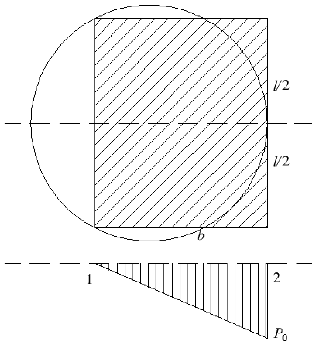
In general [13], when the additional stress induced by local surface building loads on the foundation is less than 10% of the self-weight stress of the foundation, it can be concluded that this additional stress does not significantly impact the safety of the foundation. Due to the towering nature of wind turbines, they exhibit heightened sensitivity to foundation deformation. Consequently, a more stringent criterion should be employed to determine the load influence depth of the wind turbine when subjected to dynamic loads. In this paper, two distinct discriminant methods [40] are employed, with the larger value of the two being considered as the load influence depth of the wind turbine. Discriminant Method One: When σz = 0.05σcz, take 1 times the wind turbine load under extreme wind speed conditions (1P, where P represents the wind turbine load under extreme wind speed conditions). Discriminant Method Two: When σz = 0.2σcz, take 4 times the wind turbine load (4P) under extreme wind speed conditions. Here, σz denotes the additional stress at the calculated depth, while σcz refers to the self-weight stress of the ground at the calculated depth. The calculation of self-weight stress [41] is presented in Equation (1). Under extreme load conditions, the bottom surface of the wind turbine foundation may partially separate, resulting in the distribution of additional stress across the foundation in a triangular load pattern. To simplify calculations, the load area can be approximated as a rectangle based on the principle of equal area. As illustrated in Figure 1, the calculation of additional stress [41] under the triangular distributed load on the rectangular area is as follows (2).
σ c z = γ 1 h 1 + γ 2 h 2 + + γ n h n = i = 1 n γ i h i
σ z = m n 2 π [ 1 m 2 + n 2 n 2 ( 1 + n 2 ) 1 + m 2 + n 2 ] p t = K t p t
In the formula, γ1, γ2, …γn is the weight of each layer of soil from top to bottom in the foundation, kN·m−3; h1, h2, …hn are the thickness of each layer of soil in the foundation from top to bottom, m; Kt is the stress distribution coefficient under the corresponding maximum stress corner under the vertical triangular distribution load, which is a function of m = L/B, n = z/B. Here, it is agreed that B is the side length along the direction of load change, whether the long side or the short side of the rectangular base, and the other side is L.
The calculations indicate that the influence depths of wind turbine loads are 13.5 m and 12.5 m, respectively, under the first and second discrimination methods. Thus, the overall influence depth of wind turbine loads is determined to be 13.5 m.
(2)
Overburden failure height
The calculation of the overburden failure height is based on an empirical formula outlined in the “Three Under” regulation. This empirical formula method is advantageous due to its strong applicability, high accuracy, and reduced workload [13]. This section primarily addresses the calculation of the caving zone height (Hm) and the fault zone height (Hli). The development of these heights is influenced by several factors, including the mechanical properties of the rock and soil above the coal seam, the mining depth, the ratio of mining thickness, and the dip angle of the coal seam. According to the engineering geological data, the mechanical properties of the rock and soil mass at the site of the proposed wind turbine in the goaf have been established. The average mining depth of the coal seam is 86 m, with an average mining thickness of 4 m and a dip angle of 9°. Accordingly, the heights of the caving zone and the fault zone are calculated using Equations (3) and (4) [13].
H m = 100 Σ M 4.7 Σ M + 1.9 ± 2.2
H l i = 20 Σ M + 10
In the formula, ∑M is the cumulative mining thickness of the coal seam, m.
According to the empirical formula presented, the maximum height (Hm) of the lower caving zone for the proposed wind turbine at the goaf site is 12.8 m, while the maximum height (Hli) of the fault zone is 50 m. Consequently, the combined maximum height of both zones is 62.8 m.
(3)
Safety distance
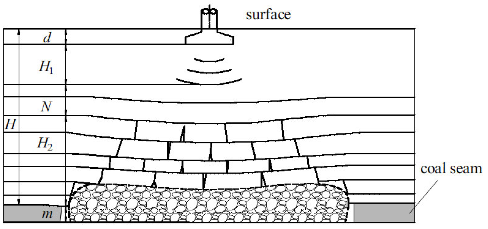
When the goaf site is in a stable state, both the caving zone and the fracture zone experience a relatively balanced state of stress. However, the application of load from the wind turbine may disrupt this equilibrium, resulting in secondary movements of the overlying rock mass. This disruption can lead to foundation deformation and damage, significantly affecting the safe operation of the wind turbine. Therefore, the disturbance of the foundation caused by the load of the wind turbine should not lead to the activation of the goaf. This implies that there must be a certain safety distance, denoted as N, between the depth of the wind turbine load and the two zones. As shown in Figure 2, the bottom curve of the wind turbine foundation indicates the additional stress caused by the wind turbine load in the foundation, the safety distance [13] can be expressed by Equation (5). The stability of the foundation is predicated on the condition that the depth of the wind turbine load does not penetrate the fault zone; specifically, when N > 0, the foundation remains in a stable state.
N = H H 1 H 2 d
In the formula, d, H1, H2 and H are the buried depth of the wind turbine foundation, the influence depth of the wind turbine load, the development height of the ‘two zones‘, the mining depth of the coal seam, m.
Based on the calculations of load influence depth, overburden caving height, and Equation (5), the minimum safety distance from the goaf above the coal seam is determined to be 11.9 m. Taking into account the mining depth of the coal seam, the development height of the two zones, the influence depth of the wind turbine load, and the geological conditions, it can be concluded that the load from the proposed wind turbine will not trigger the activation of the goaf, ensuring that the foundation remains in a stable state.

2.1.3. Foundation Deformation Calculation

The vertical deformation of the foundation in the goaf can be categorized into three types: additional deformation (S1), residual deformation (S2), and activation deformation (S3) [40]. In the calculation of the foundation deformation of the wind turbine located at the goaf site, vertical deformation is primarily considered. This includes additional deformation, residual deformation, and activation deformation. The foundation deformation S of the wind turbine in the goaf site is:
S = S 1 + S 2 + S 3
From the above analysis, it can be concluded that the loads imposed by the wind turbine will not trigger the activation of the goaf, which implies that S3 equals 0. Therefore, the foundation deformation of the wind turbine located at the goaf site can be expressed as S = S1 + S2.
(1)
Compression deformation of strata
The compressive deformation of the stratum refers to the compressive settlement (in mm) of the rock and soil layers under the influence of wind turbine loads, which can be calculated using the layered summation method. From the analysis presented, it can be concluded that the additional pressure exerted on the wind turbine base under extreme wind speed conditions follows a triangular distribution. The additional pressure exerted by the triangular distribution will lead to uneven settlement of the foundation. Consequently, it is essential to calculate the settlement under both the conditions of zero additional pressure and the maximum additional pressure at the base. This calculation is necessary to verify whether the settlement and inclination of the foundation satisfy the specified requirements. Based on the overall project context and the calculations presented in Figure 1, it can be concluded that the dimensions are l = 16.01 m and b = 14.59 m under rated wind speed conditions, and l = 7.82 m and b = 11.85 m under extreme wind speed conditions. According to Equation (7), the calculated depths for both rated and extreme wind speed conditions are 21 m and 18 m, respectively. The settlement at both ends under the triangular distributed load can be determined using the corner point method. Detailed calculations are provided in Table 3 and Table 4.
Z n = b ( 2.5 0.4 ln b )
In the table: zi is the depth under the base; b is the side length of the direction of triangular distribution load on the equivalent rectangular area, m; l is half of the length of the other side of the triangular distribution load on the equivalent rectangular area, m; α ¯ i is the average additional stress coefficient of the i layer; Δsi is the deformation value of the i-layer soil, mm.
According to the results presented in Table 4 and derived from Formula (8), the equivalent value of the compression modulus of the soil layer within the specified calculation range under rated wind speed can be determined [42]. According to the equivalent value of the compression modulus, the empirical coefficient for settlement calculation, denoted as ψs, is 0.42. The final settlements at points 1 and 2 under rated wind speeds are 4.76 mm and 24.95 mm, respectively. Similarly, under extreme wind speed conditions, the final settlements at foundation points 1 and 2 are 9.60 mm and 40.48 mm, respectively.
E s ¯ = Σ A i Σ A i E s i
In the formula, E s ¯ is the equivalent value of compression modulus (MPa); Ai is the integral value of the additional stress coefficient of the i-layer soil along the thickness.
(2)
Surface residual deformation
Surface residual deformation refers to the deformation of the ground surface resulting from mining activities that have occurred since the initiation of engineering construction. This deformation can be predicted using the probability integral method. When the average mining depth of the goaf is less than or equal to 400 m, the duration of surface deformation associated with the goaf is 2.5 times the mining depth. The average mining depth of the goaf is 90 m, and the calculated duration of surface movement is 225 days. Based on the site conditions of the goaf, it is identified as an old goaf. The surface movement resulting from coal seam mining has concluded, and the goaf is currently in a stable state.
Scholar Knothe found that the surface settlement velocity is proportional to the residual settlement deformation value at a specific moment [43]. By combining this finding with the initial conditions of the settlement at the goaf site, a functional formula for the surface deformation of the goaf over time has been derived.
W ( t ) = W m ( 1 e c t )
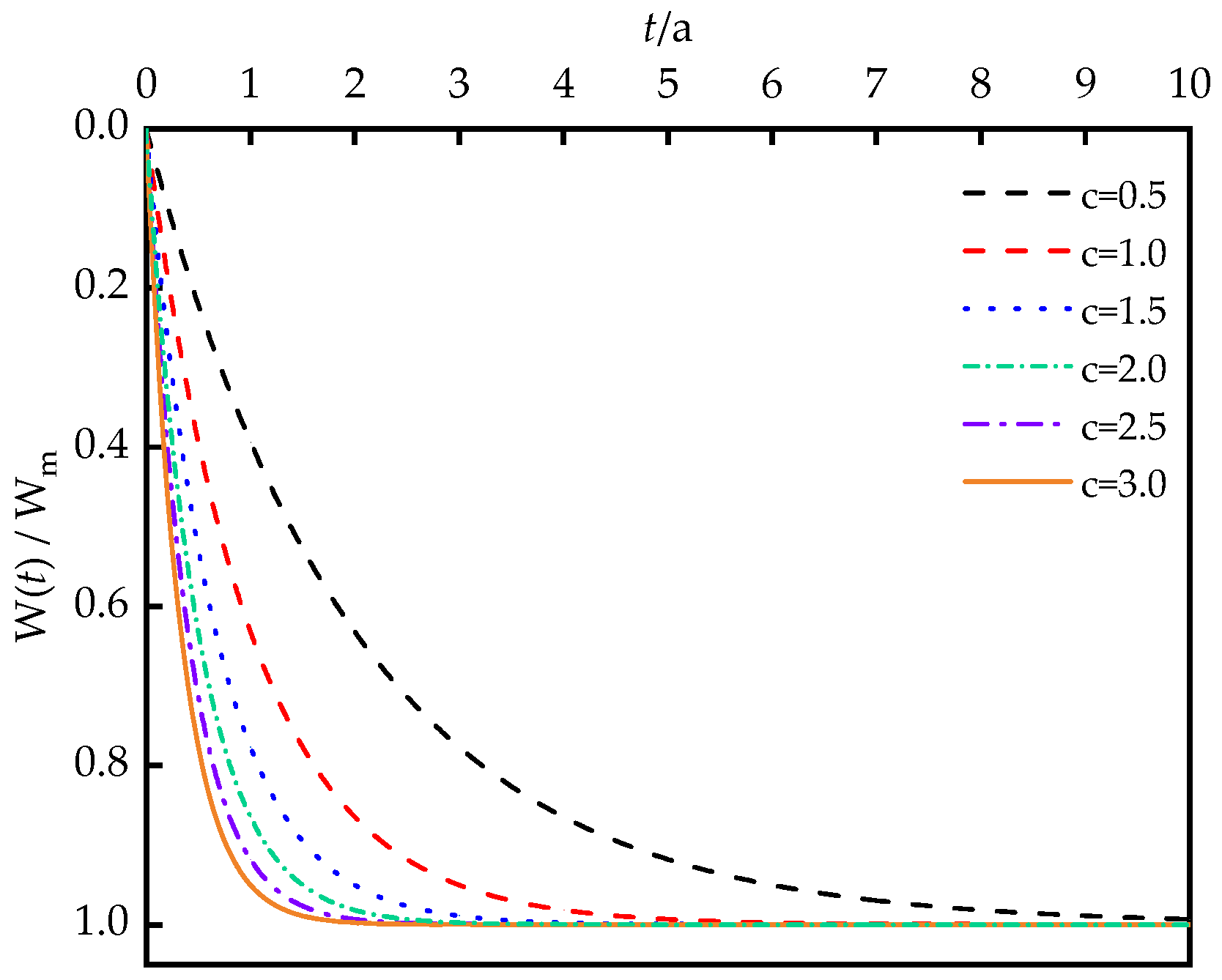
In the formula, W(t) is the completed settlement, mm; Wm is the maximum settlement; and c is a time-dependent parameter related to the mechanical properties of the overlying strata. When the c value of the harder strata is 1.0~1.5, and the c value is different, the relationship between the subsidence and time is shown in Figure 3.
Considering the mechanical properties of the overlying strata and the depth of coal seam mining in the goaf, the value of c is 1.3. According to the formula, when t = 5, W(t)/Wm is 0.99850, when t = 8, W(t)/Wm is 0.99997. For the old goaf, the residual settlement rate is minimal. In comparison to the compressive deformation caused by the wind turbine load, this residual deformation can be considered negligible. Therefore, the foundation settlement of the goaf under the wind turbine load is equivalent to the stratum compression S1.
(3)
Activation deformation of foundation
The activation deformation refers to the recompression deformation of the caving zone, which is caused by the load influence depth of the wind turbine as it enters the fault zone. As discussed in Section 2.1.3, there exists a specific safety distance between the load influence depth of the wind turbine and the two zones of the goaf under extreme wind speed conditions. This indicates that the load exerted by the wind turbine will not induce activation deformation in the goaf site, resulting in S3 = 0. Consequently, the foundation deformation of the goaf associated with the wind turbine can be expressed as S = S1 + S2.
The calculation results indicate that the maximum settlement of the goaf foundation under rated wind speed conditions is 25.2 mm, while under extreme wind speed conditions, it reaches 40.73 mm. Both values fall within the allowable limits specified in the guidelines.

2.2. Model Test of Foundation Interaction in Goaf of Wind Turbine

2.2.1. Similar Model Test Design

In the process of establishing the similarity theory for wind turbine models, the wind turbine structure is simplified as a whole [44]. In this simplified model, the wind turbine tower is treated as an Euler–Bernoulli beam subjected to axial force. It is assumed that both the bending stiffness and mass per unit length of the beam remain constant along the height of the structure, and that the magnitude and direction of the axial force remain unchanged during the lateral displacement of the beam. The impeller, generator, gearbox, and other components situated atop the wind turbine can be considered as a concentrated mass block, denoted as M, which is rigidly connected to the tower.
According to the similarity theory proposed by Bhattacharya, the wind turbine model must adhere to the following dimensionless relationship: (1) Geometric similarity: It is essential to ensure that the model structure and the prototype structure maintain the same geometric scale. (2) Quality similarity: It is imperative to confirm that the upper structure, tower, and foundation of the wind turbine possess the same mass scale. (3) Load height similarity: It is crucial to ensure that the load height corresponds to the scale of the wind turbine height. The relevant parameters of the wind turbine are presented in Table 5.
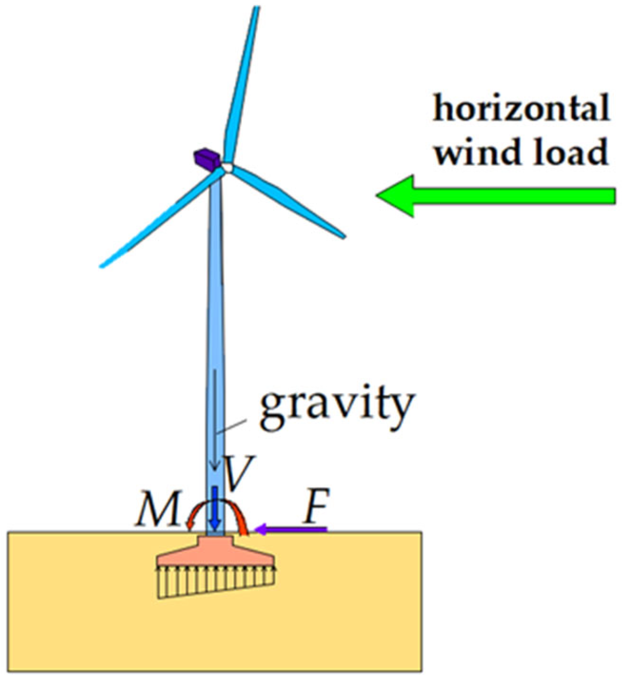
According to the test purpose and site conditions, the geometric similarity ratio of the foundation model is 1:100, the density similarity ratio is 1:1.5, and the acceleration similarity ratio is 1:1. The wind turbine foundation model and the prototype are constructed from the same grade of concrete, resulting in both the density similarity ratio and the elastic modulus similarity ratio being 1:1. The similarity ratios of the remaining physical quantities can be calculated using the dimensional analysis method, as demonstrated in Table 6. The wind turbine foundation primarily bears the bending moment, shear force, and vertical force transmitted from the superstructure. The vertical force arises from the self-weight of the wind turbine tower and the upper structure of the wind turbine, as illustrated in Figure 4.
Based on the mass similarity and base pressure similarity outlined in the aforementioned similarity theory, it is essential to weigh the top structure, tower, and foundation of the wind turbine to 13.3 kg, 17.8 kg, and 109.4 kg, respectively, in order to satisfy the test similarity requirements.
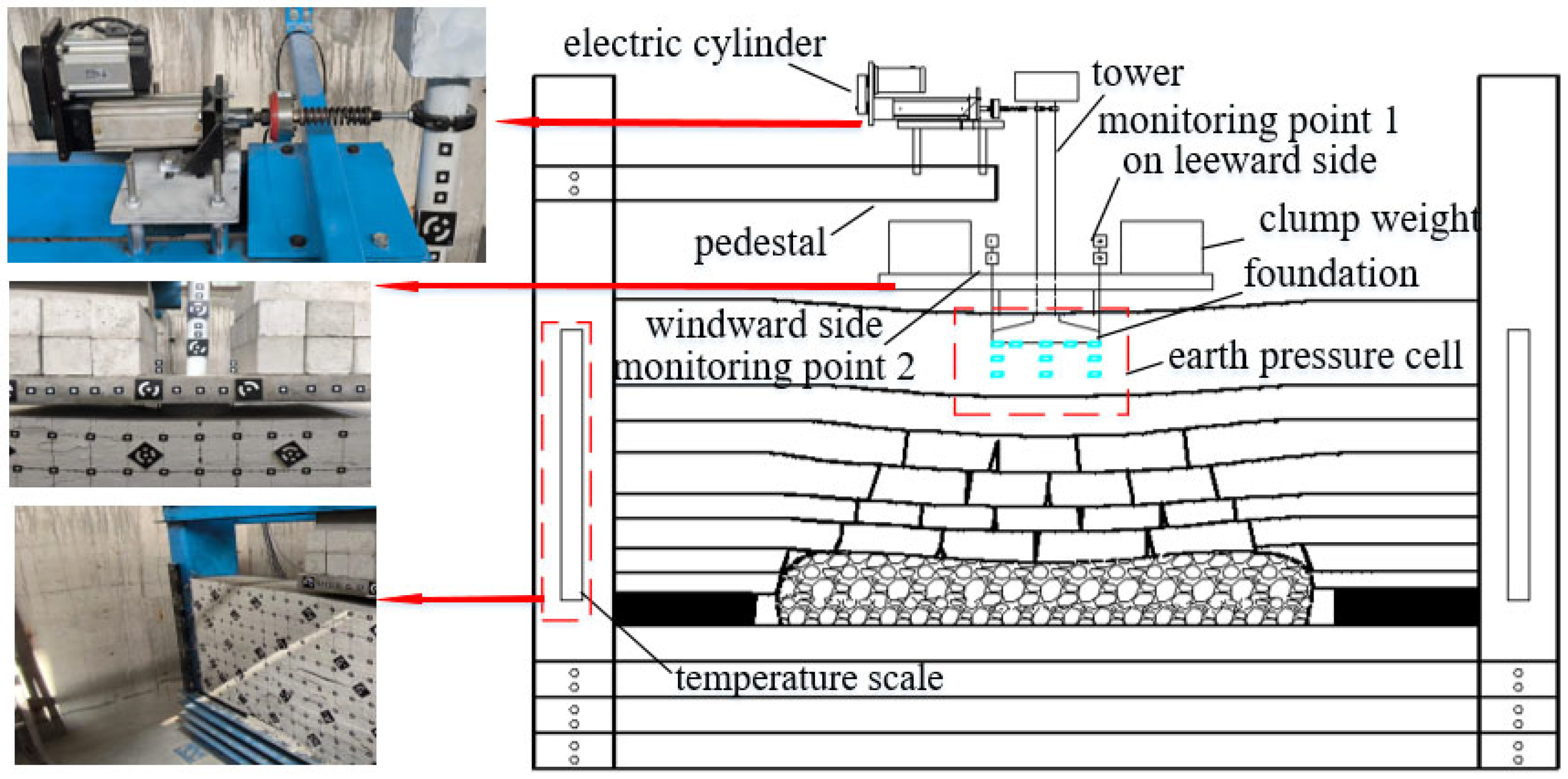
In this experiment, a set of cyclic load application devices for wind turbines in the goaf site is designed. The wind load loading system WLS-2000 (50) is composed of four main parts: electric servo cylinder, servo dynamic system control software, controller and electric servo valve. The test loading device is shown in Figure 5. The electric cylinder primarily consists of a servo motor, a cylinder, a force sensor, a displacement sensor, a temperature sensor, and additional components. It has a maximum stroke of 60 mm, a maximum output load of 2000 N, and a maximum frequency of 50 Hz. In the process of applying wind load, the control software automatically tracks and corrects the peak and valley values of the control quantity (load) to ensure that the dynamic error of each peak value throughout the entire testing process does not exceed 1%.

2.2.2. Similar Model Making

According to the similarity principle, the foundation model is constructed layer by layer using river sand as the aggregate, with lime and gypsum serving as the cementing materials. Based on formulas (10) and (11), the compressive strength of the rock is determined [45]. The ratio of each rock layer can be obtained by consulting relevant research literature, ensuring that the similar materials of different rock layers achieve the corresponding compressive strength after filling. This approach facilitates the similarity required for the geomechanical model test. The mechanical parameters of the rock strata are presented in Table 7.
C σ = C L C γ
R m = R c / C σ
In the formula, Cσ, CL and Cγ are stress similarity constants, geometric similarity constants, and severe similarity constants. Rm and Rc are similar compressive strength of rock strata, compressive strength of rock strata, MPa.
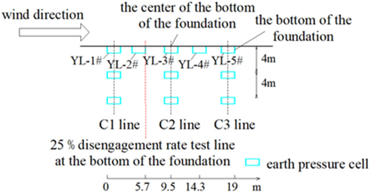
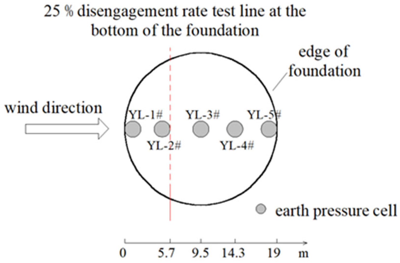
After the coal seam has been excavated and the overlying strata in the goaf have stabilized, the wind turbine model can be positioned on the surface. Firstly, an earth pressure box is installed at the bottom of the foundation. Three measuring lines (C1, C3, C2) are arranged along the depth direction on the windward side, the leeward side, and the base center of the foundation. Each measurement line consists of three earth pressure boxes, arranged with a vertical spacing of 4 m. The configuration of the earth pressure boxes is illustrated in Figure 6, while the arrangement of the base earth pressure boxes is depicted in Figure 7. Following the leveling of the surface, the foundation is installed and backfilled with similar materials. Subsequently, the tower and the top counterweight are assembled sequentially.

2.3. Subsection Numerical Simulation of Foundation Disaster Mechanism in Goaf of Wind Turbine

2.3.1. Establishment of Numerical Model

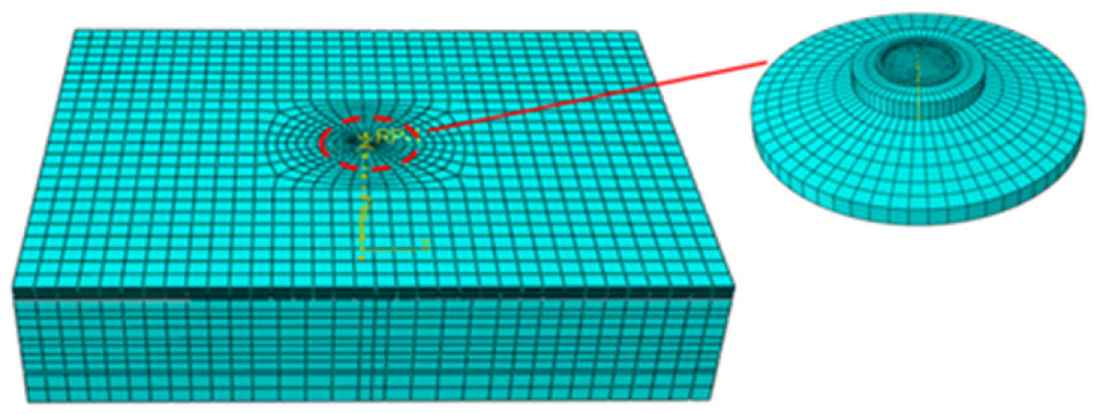
To simulate the settlement deformation, inclination rate, and foundation failure process of the wind turbine foundation in a goaf site, a 1:1 numerical model of the foundation and the wind turbine was established using the finite element software ABAQUS 2020, as illustrated in Figure 8. The dimensions of the foundation in the goaf are 520 m × 400 m × 120 m, while the area of the goaf measures 180 m × 120 m. Additionally, the foundation has a diameter of 19 m and a height of 3 m.
In the modeling of the wind turbine foundation, an integral modeling approach is employed wherein steel and concrete are treated as homogeneous materials, eliminating the need for separate modeling of these components. Furthermore, the superstructure of the wind turbine foundation, which includes the tower, rotor, and gearbox, is not modeled individually; instead, it is simplified to a vertical load applied at the top of the foundation.

2.3.2. Model Parameter Selection

Based on finite element theory and relevant research findings from various scholars, this paper assumes that the deformation between the foundation concrete and the foundation ring, as well as between the foundation concrete and the cushion, is fully coordinated. Therefore, a binding constraint is employed to establish the connection. Due to the potential for relative displacement or detachment between the concrete cushion and the foundation soil, it is essential to establish a general contact condition at the interface between these two components. The friction coefficient between the cushion and the underlying soil, as well as between the foundation concrete and the surrounding soil of the foundation pit, and the contact surface between the foundation concrete and the backfill soil is uniformly set to 0.3 [46]. Fully constrained boundary conditions are applied to the bottom of the foundation in the goaf, while corresponding horizontal constraints are imposed on the free surface surrounding the foundation model. The numerical model parameters are shown in Table 8.

3. Results

3.1. Analysis of Model Test Results

3.1.1. Displacement Analysis

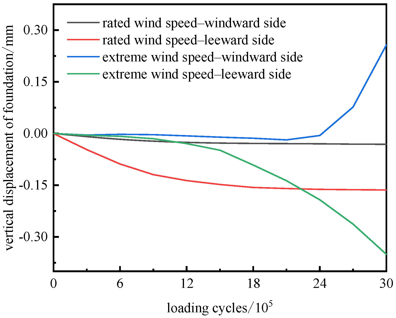
Figure 9 illustrates the variation in the vertical displacement of the foundation as a function of the number of loading cycles under extreme wind speed and rated wind speed conditions. The distinct loading methods employed in these two scenarios result in significant differences in the vertical displacement of the foundation. Specifically, under rated wind speed conditions, the vertical displacement of the foundation increases rapidly during the initial loading phase, leading to substantial settlement on both the windward and leeward sides. As loading cycles increase, the settlement gradually stabilizes. This phenomenon occurs because the density of the foundation soil increases with prolonged loading, leading to a gradual decrease in compressibility, which in turn reduces the incremental settlement of the foundation. Under extreme wind speed conditions, the vertical displacement of the foundation changes slowly at low load levels. However, as the load level increases, the windward side of the foundation exhibits an upward rise. Due to the gradual separation of the foundation slab from the foundation, there is no constraint on the rotation of the void area. This lack of constraint leads to a rapid increase in the vertical displacement on the windward side of the foundation and contributes to the progressive uneven settlement of the foundation.

3.1.2. Dip Analysis

By adjusting the coordinates of the vertical displacement monitoring points located on both sides of the foundation, as well as the monitoring points positioned on the surface of the tower, the variation in the inclination angles of both the foundation and the tower can be accurately calculated. Figure 10 illustrates the change in the inclination angle of the foundation under two working conditions. Under the rated wind speed condition, the curve representing the inclination angle of the foundation and the tower exhibits a convex shape as a function of the number of loading cycles. During the initial loading phase, the inclination angle of both the foundation and the tower increases rapidly with the number of loading cycles. Subsequently, as the number of loading cycles continues to rise, the inclination angle of the foundation and the tower begins to decrease and gradually approaches a more stable state. Under extreme load conditions, the curve representing the relationship between the inclination angle and the load grade of the foundation and tower is generally concave. At low load levels, the inclination angle of both the foundation and the tower increase gradually. When the load level reaches level 8, the inclination angle of both the foundation and the tower increases rapidly due to the gradual disengagement of the windward base. After the test loading, the inclination angle of the foundation measures 0.18°, which is 80% of the allowable value specified (0.22°). This significant inclination poses a considerable risk to the safety of the wind turbine.
Due to the relative stability of the goaf site and the minimal disturbance caused by extreme wind loads to the foundation, there exists a safety distance between the depth affected by the wind turbine load and the ‘two zones’. The primary cause of foundation settlement is the compressive deformation of the foundation soil. Additionally, the inclination of both the foundation and the tower arises predominantly from uneven settlement of the foundation.

3.1.3. Earth Pressure Analysis

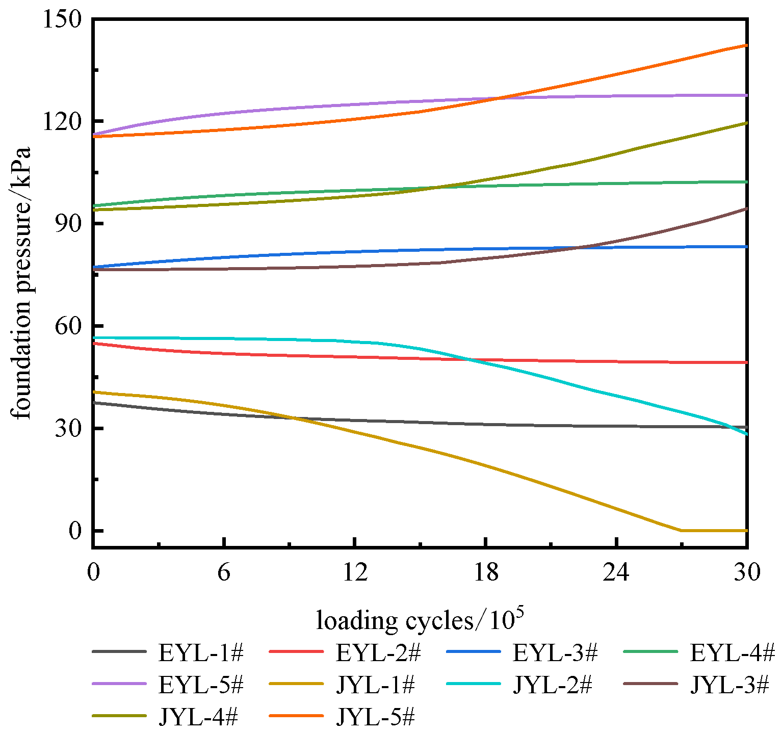
The variation in base pressure with loading cycles under different working conditions is shown in Figure 11 (EYL-1 # represents No. 1 earth pressure box data under rated wind speed conditions, JYL-1 # represents No. 1 earth pressure box data under extreme wind speed conditions). Figure 12 illustrates the variation in base pressure with loading cycles under different working conditions. The data for EYL-1 # corresponds to the No. 1 earth pressure box under rated wind speed conditions, while JYL-1 # represents the No. 1 earth pressure box data under extreme wind speed conditions. The foundation primarily bears the bending moment generated by the upper horizontal force. This bending moment causes the soil beneath the foundation to migrate, resulting in varying pressure values at different positions of the foundation. Consequently, the pressure exerted on the foundation is closely related to the magnitude of the horizontal load; specifically, an increase in the horizontal load corresponds to a decrease in the pressure on the windward side of the foundation. During the load application process under rated wind speed conditions, the settlement of the windward side of the foundation is less than that of the leeward side. Consequently, the pressure at the bottom of the windward side foundation decreases as the number of loading cycles increases, while the pressure at the bottom of the leeward side foundation continues to rise. As the loading cycles increase, the compressibility of the foundation soil gradually decreases, leading to a stabilization of the foundation’s deformation. Consequently, the rate of change in pressure at the bottom of the foundation gradually slows down. Under extreme wind speed conditions, the pressure at the bottom of the foundation increases progressively from the windward side to the leeward side. Notably, the pressure at the bottom of the windward side foundation is significantly lower than that of the leeward side. As the load level rises, the pressure at the bottom of the windward side foundation decreases, while the pressure at the bottom of the leeward side foundation correspondingly increases. When the load level reaches 8, the pressure at the bottom of the foundation on the leeward side continues to increase, while the pressure at the bottom on the windward side continues to decrease. Additionally, the earth pressure at the edge of the windward side of the foundation becomes negative, indicating that the bottom of the foundation has experienced voiding. As the load further increases, the uneven distribution of pressure at the bottom of the foundation becomes more pronounced, and the phenomenon of voiding at the edge of the foundation becomes more evident. At this stage, the earth pressure on the windward side is 0.
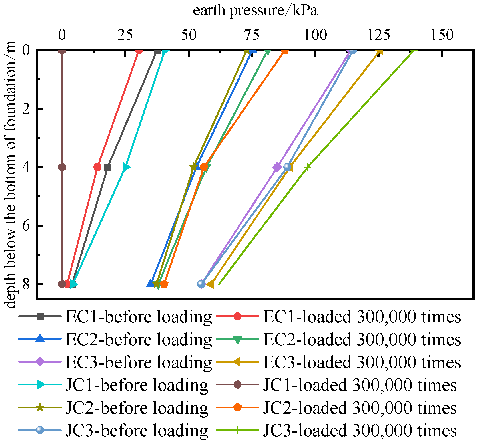
The variation in earth pressure at different positions with loading cycles under rated wind speed conditions and extreme wind speed conditions is shown in Figure 12 (EC1 is the earth pressure of C1 line under rated wind speed conditions, JC1 is the earth pressure of C1 line under extreme wind speed conditions). Figure 10 illustrates the variation in earth pressure at different positions over time under both rated and extreme wind speed conditions. EC1 represents the earth pressure of the C1 line under rated wind speed conditions, while JC1 denotes the earth pressure of the C1 line under extreme wind speed conditions. Under the condition of rated wind speed, the rate of earth pressure change with depth exhibits significant variation across different measuring lines. Notably, the attenuation rate of earth pressure with depth at the C3 measuring line is approximately 2.4 times greater than that at the C1 measuring line. Furthermore, the stress diffusion range at the C3 measuring line exceeds that at the C1 measuring line during the load transfer process. Under extreme wind speed conditions, the continuous application of load results in a continuous decrease in earth pressure at the C1 survey line, while the earth pressure at the C2 and C3 survey lines shows a continuous increase. This phenomenon can be attributed to the increasing frequency of loading and the ongoing elevation of the load level. Under horizontal load, the uneven distribution of pressure at the base of the foundation becomes increasingly pronounced. The edge of the windward side of the foundation gradually experiences a decrease in pressure, while the pressure at the base of the leeward side increases.
The earth pressure along the three survey lines decreases nonlinearly with increasing depth under various working conditions and loading stages. During the loading process, the earth pressure at the bottom of the foundation is the highest, while the pressure decreases with depth, indicating a significant unloading phenomenon in the upper rock mass of the goaf. Furthermore, as the depth below the foundation increases, both the earth pressure and the influence of the upper load disturbance on the rock mass diminish.

3.2. Analysis of Numerical Simulation Results

3.2.1. Vertical Displacement

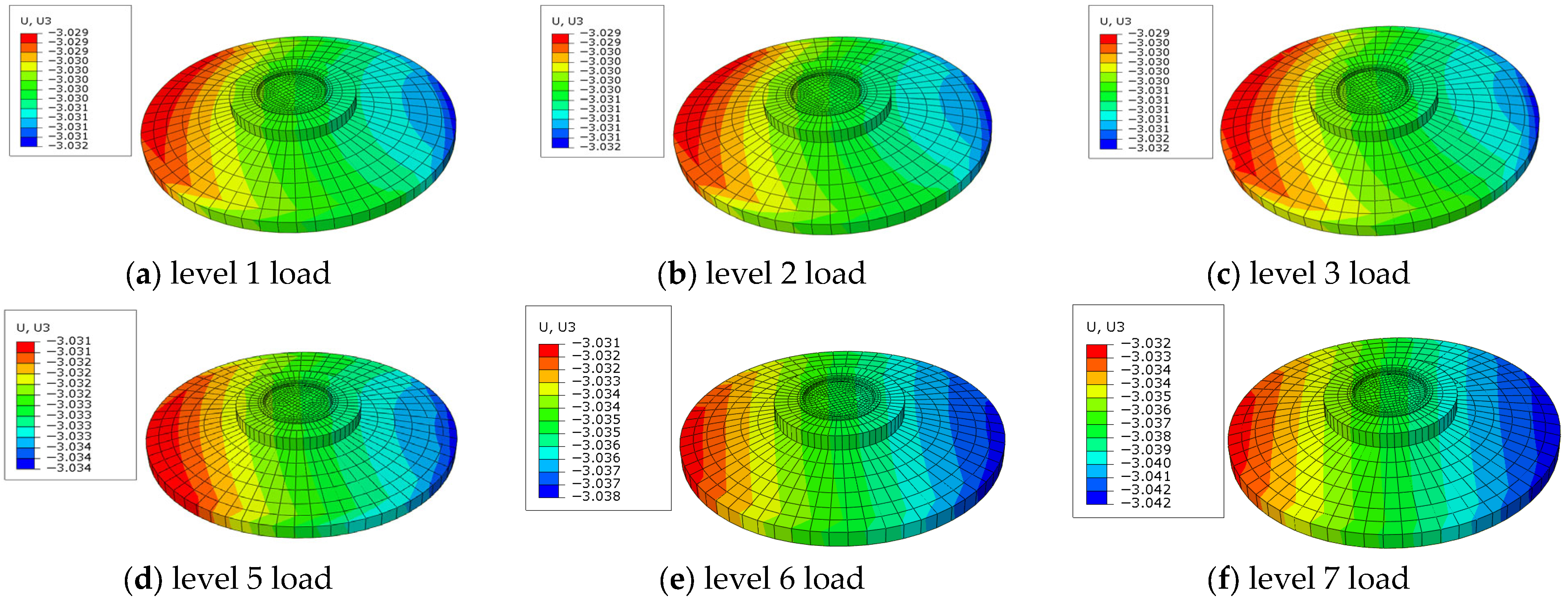
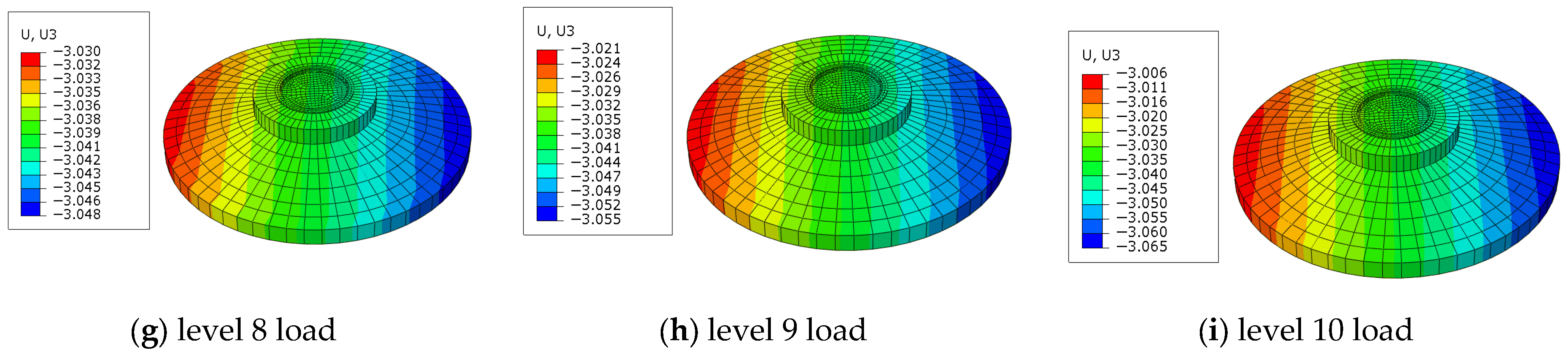
As shown in Figure 13, the vertical displacement changes in the foundation after the application of different load levels are presented. The foundation settlement is calculated by subtracting the surface settlement value at the corresponding position before loading from the settlement value indicated in the figure. The left side of the figure represents the windward side of the foundation, while the right side represents the leeward side. It can be observed from the figure that the foundation settlement continues to increase in the direction of the wind. Specifically, the vertical displacement from the windward side to the leeward side of the foundation gradually increases. When the load level is below 8, both the windward and leeward sides of the foundation experience an increase in settlement as the load level rises. However, the rate of change on the windward side is significantly less than that on the leeward side. When the load level reaches 8, an increase in the load level results in a negative growth in the settlement of the windward side of the foundation. This indicates that the windward side of the foundation gradually separates from the foundation and is lifted upward, while the vertical displacement of the leeward side of the foundation continues to increase downward. The discrepancy in settlement variation laws on either side of the foundation can be attributed to the eccentric loading state induced by horizontal forces, resulting in an uneven distribution of base pressure. This differential pressure leads to varying settlements on both sides of the foundation. As the horizontal load intensifies beyond a certain threshold, the windward side of the foundation begins to detach from the base, causing it to rise, while the vertical displacement of the leeward side continues to increase downward.

3.2.2. Foundation Dip Angle

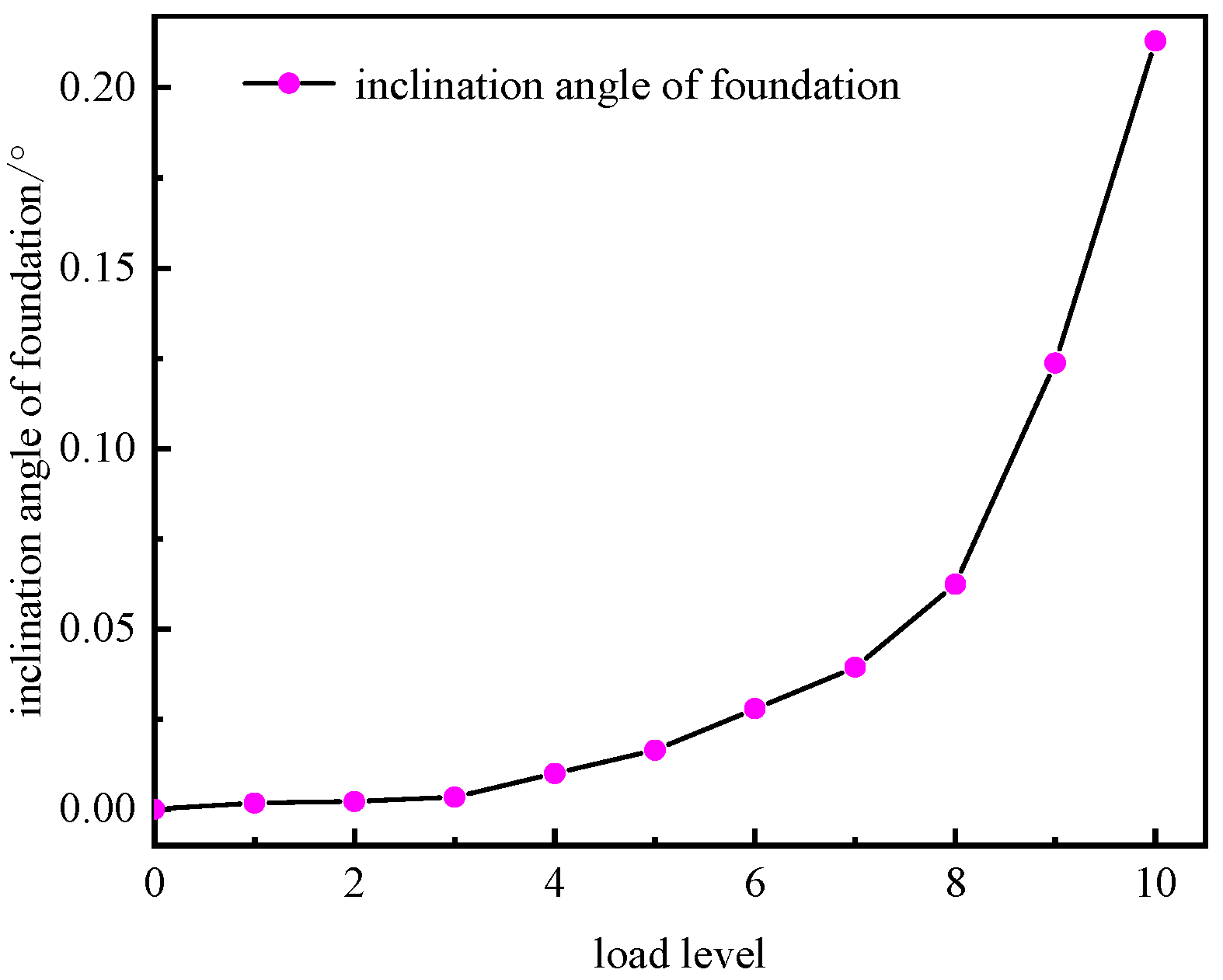
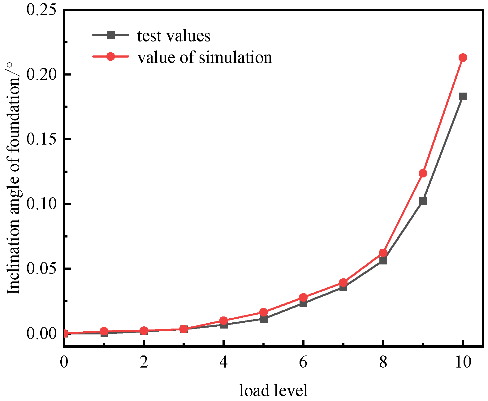
Under the influence of horizontal wind load, the foundation experiences an eccentric loading state, resulting in uneven settlement. Consequently, the foundation exhibits a certain degree of inclination. The inclination curve of the foundation at various load levels during the loading process is illustrated in Figure 14. The figure illustrates that the growth rate of the foundation’s inclination angle increases with the load level, exhibiting an overall concave curvature. When the load level is below grade 3, the curve changes more gradually. This is attributed to the low load level, which results in minimal compression deformation of the foundation under wind load. Consequently, the unevenness of the foundation is not pronounced, leading to a smaller inclination of the foundation. As the load level increases to level 4, the inclination angle of the foundation gradually rises. Once the load level exceeds 8, the curve of the foundation inclination angle steepens, resulting in a rapid increase in the inclination angle. This phenomenon occurs because, at a load level of 8, the windward side of the foundation becomes evident. The foundation in a void position is relatively unconstrained, resulting in increased pressure from the base on the leeward side. Consequently, the foundation is more susceptible to tilting under horizontal wind loads, leading to a rapid increase in the inclination angle. Once the load is applied, the maximum inclination angle of the foundation reaches 0.21°, approaching the allowable limit set by specifications. At this point, the inclination poses a significant threat to the safety of the wind turbine.

3.2.3. Foundation Stress Analysis

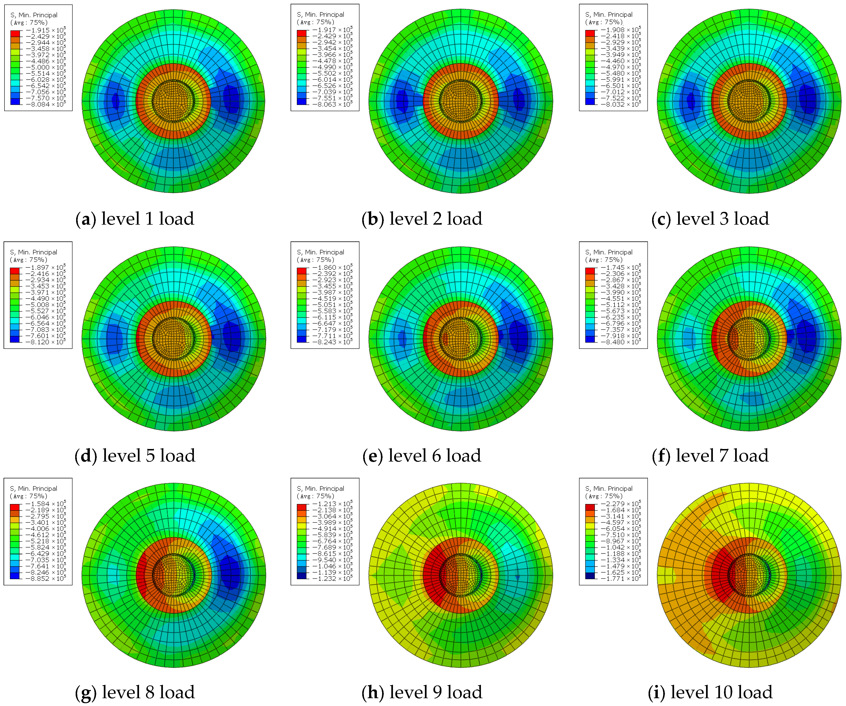
In ABAQUS post-processing, S. Min. principal denotes the third principal stress of the element, commonly utilized as an index for compressive stress in structural analysis. The distribution of foundation compressive stress at various loading stages is illustrated in Figure 15. From the figure, it is evident that stress concentration areas develop along the horizontal load direction during the loading process, specifically located on the left and right sides of the column. This phenomenon occurs because the foundation is subjected to horizontal load and bending moment. As the load level increases, the compressive stress on the right side of the foundation rises, while the compressive stress concentration on the left side diminishes. At a load level of 8, the stress concentration area on the left side of the foundation is significantly reduced, whereas the stress concentration on the right side continues to increase. Consequently, the stress on the left side of the top surface of the foundation is the lowest.

3.3. Comparative Analysis of Model Test and Numerical Simulation Results

3.3.1. Vertical Displacement

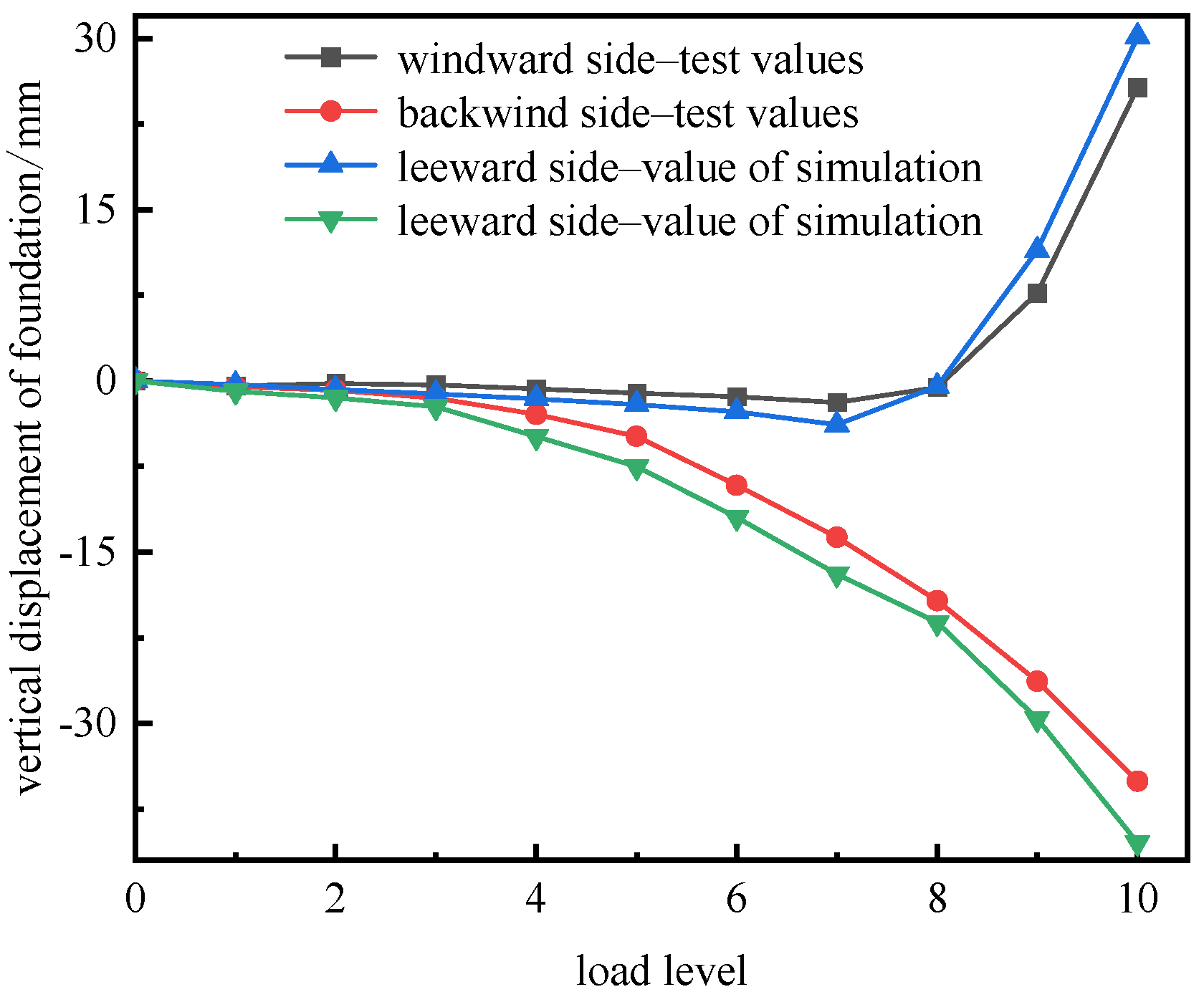
According to the similarity theorem, the vertical displacement of the foundation obtained from the model test is amplified by a factor of 100 to derive the actual settlement value of the foundation. The model test data and the numerical simulation data are presented in Figure 16. The diagram illustrates that the overall trend of the load–displacement curve for the foundation, as obtained from both the model test and the numerical simulation, is consistent. When the wind load is minimal, both the windward and leeward sides of the foundation exhibit downward vertical displacement, resulting in a slow settlement rate. Conversely, as the load level increases, the settlement rate of the foundation accelerates. When the wind load reaches a specific threshold, the windward side of the foundation progressively detaches from the foundation itself, creating a void. Consequently, the vertical displacement of the windward side of the foundation begins to increase. Due to the interaction changes between the foundation and the superstructure, the vertical displacement rate on the windward side accelerates under horizontal wind loads. Conversely, the vertical displacement on the leeward side consistently moves downward, with the settlement rate gradually increasing as the load level rises.

3.3.2. Tilt Comparison

The similarity theorem indicates that the inclination angle of the foundation in the model test corresponds directly to that of the prototype. Therefore, it is unnecessary to amplify the inclination angle of the foundation in the model test by any specific multiple. As illustrated in Figure 17, the experimental values of the foundation inclination angle align closely with the simulated values. When the load level is low, there is no significant difference between the experimental and simulated values. As the load level increases, discrepancies between the two values emerge. Nevertheless, the overall trends of the experimental and simulated values remain consistent. This indicates that the parameters chosen for the model are reliable for numerical simulation analysis.

4. Discussion

The extensive coal mining subsidence areas created by large-scale coal extraction in China offer significant land resources for the development of the wind power industry. However, the inherent characteristics of rock mass fragmentation and the complex stress states at these sites, combined with the periodic and dynamic nature of wind loads, render the investigation of the disaster mechanisms affecting wind turbine foundations a critical scientific challenge that limits the safe construction of wind power projects in such specialized environments [3,16]. Existing research predominantly emphasizes the mechanical properties of wind turbine foundations in conventional sites, while systematic investigations into the disaster dynamics of wind turbine foundations in goaf sites remain relatively scarce [17,40]. This paper delves into the disaster evolution mechanisms of wind turbine foundations in goaf areas through a comprehensive approach that integrates theoretical analysis, similar model testing, and numerical simulation. Furthermore, it provides an in-depth analysis and discussion, linking these findings with relevant research outcomes.
The core of evaluating foundation stability at goaf sites lies in quantifying the coupling effect of wind dynamic loads and the geological characteristics of the goaf—a challenge that remains inadequately addressed in existing research. Utilizing the stress analysis method, Ren et al. [17,18,19] proposed a criterion for the ‘activation’ of foundations in goaf; however, they did not develop a quantitative evaluation system for wind turbine loads. Additionally, Li et al. [13] compared various stability analysis methods for building foundations in goaf but overlooked the sensitivity of high-rise structures to foundation deformation. In this study, we innovatively combine the additional stress method with the load influence depth criterion (σz = 0.05σcz, σz = 0.2σcz), determining that the maximum influence depth of wind turbine load under extreme wind speed conditions is 13.5 m. Utilizing engineering geological data and the empirical formula of the ‘three under’ regulations [13], we calculate the development height of the caving fault zone in the goaf to be 62.8 m. Subsequently, by applying the safety distance formula, we derive the minimum safety distance above the coal seam to be 11.9 m, thereby forming an integrated evaluation system of ‘load influence depth-overburden rock failure height-safety distance’ for the goaf site. This system clarifies the quantitative control boundary for wind turbine construction at the goaf site and aligns scientifically with the suitability evaluation of the foundation in the goaf site proposed by Ren et al. [40]. Moreover, the Knothe time function is employed to quantitatively verify that the residual deformation of the old goaf can be disregarded (the settlement completion rate reaches 99.997% when t = 8), thus enhancing the calculation method for ground deformation of the wind turbine in the goaf site.
The disaster mechanism characterized by horizontal dynamic loads is a fundamental mechanical aspect of wind turbine foundations situated in goaf sites, which fundamentally differs from those in conventional locations. Deng et al. [38,39] established that horizontal loads can easily induce plastic yielding in the windward soil, leading to the overturning of the foundation, based on their investigations in conventional settings. This paper presents model test findings indicating that goaf sites exhibit significantly greater stress inhomogeneity due to the presence of rock mass cracks and separation layers. Under extreme wind speed conditions, the pressure differential between the two sides of the base reaches 139 kPa, which is 1.5 times greater than that observed at rated wind speeds. Moreover, the disturbance depth on the leeward side is notably larger than that on the windward side. This disparity fundamentally arises from the heterogeneity of the foundation soil in the goaf, which distorts the stress transfer path, contrasting with the ‘uniform load diffusion’ characteristics reported by Zhu et al. [44] in conventional sites. In the rated wind speed condition, the accumulation of soil strain at the foundation leads to the gradual evolution and stabilization of turbine foundation settlement as the number of loading cycles increases, with a maxi-mum tilt angle of 0.04°. Under extreme wind speed conditions, when the load level reaches 8, a voiding phenomenon occurs on the windward side, resulting in a rapid in-crease in the tilt angle to 0.18° (which is 80% of the value permitted by the code). Following the occurrence of voiding, the rotational resistance of the foundation is significantly reduced. This finding further refines the ‘foundation-soil interaction failure’ theory proposed by Paolo et al. [30] and provides a quantitative basis for the early warning of catastrophic risks in wind turbine foundations.
The heterogeneity in the spatial distribution of soil pressure further elucidates the stress characteristics of the wind turbine foundation situated in the goaf. The test data collected from the three lines indicate that the earth pressure exhibits a nonlinear attenuation trend with depth, where the attenuation rate of earth pressure on the leeward side (C2 line and C3 line) is significantly lower than that on the windward side (C1 line). At a depth of 8 m beneath the foundation, the leeward side maintains a high earth pressure value, whereas the windward side approaches 0. This observation markedly deviates from the uniform distribution model of the foundation reaction force for conventional site wind turbine foundations proposed by Liu et al. [37]. The underlying principle is that stress diffusion distortion arises from the heterogeneity of the foundation in the goaf, which also elucidates the primary cause of uneven settlement of the foundation from a mechanical perspective. Shi et al. [16] confirmed that the inhomogeneity of foundation stress exacerbates structural damage. This study further investigates the degree of stress inhomogeneity of wind turbine foundations in the goaf site and provides targeted mechanical parameter support for the design of foundation anti-overturning measures.
The scientific validity and reliability of the research are substantiated through the integration of ABAQUS numerical simulations and model tests [30]. Unlike the conventional site numerical simulations conducted by Ding et al. [35], this study incorporates the geological characteristics of the goaf to establish differentiated rock mechanics parameters, thereby enhancing the model’s applicability to the actual working conditions of specific sites. In contrast to Xu et al.’s [46] simulation of ‘structure-foundation-soil’ interaction, which primarily focuses on static loading, this study achieves a numerical reconstruction of the disaster process affecting wind turbine foundations in goaf under cyclic horizontal loads, clearly elucidating the evolution of stress attenuation on the windward side and stress concentration on the leeward side.
This study has several limitations: the coupling effects of seismic loads, ground-water seepage, and potential activation deformation of goaf are not fully considered [17,19]. Additionally, the classification standard for the ‘activation’ of goaf proposed by Ren et al. [19] indicates that multi-factor coupling may exacerbate the risk of catastrophic events. Furthermore, there is a lack of long-term verification of field-measured data. In comparison to the research method employed by Wei et al. [26], which utilizes field monitoring in conjunction with numerical simulation, the engineering applicability of this study requires further enhancement. Future research should expand the multi-factor coupling analysis, conduct disaster tests on high-power wind turbine foundations, and implement long-term monitoring in conjunction with actual projects. Moreover, the foundation precision grouting reinforcement technology proposed by Guo et al. [11] can serve as a reference for exploring disaster prevention and control measures for wind turbine foundations situated in goaf sites, thereby providing more comprehensive technical support for the safe construction of wind power engineering in specialized locations.
In summary, this study systematically reveals the mechanical laws and catastrophic evolution characteristics of wind turbine foundations in goaf sites through a combination of theoretical analysis, model testing, and numerical simulation. This research establishes a strong academic connection with existing studies and achieves an innovative breakthrough in theory and methodology concerning the unique characteristics of these sites. It provides academic support and technical references for the design, as well as risk prevention and control, of wind turbine foundations in goaf sites, holding significant theoretical value and engineering importance for promoting the utilization of land resources in goafs and the sustainable development of the wind power industry.

5. Conclusions

As the primary energy source in China, coal mining has resulted in the formation of numerous goafs. With the ongoing advancement of green energy, particularly in wind power construction, the feasibility of erecting wind turbines on these goaf sites must be considered. However, significant safety risks are associated with the construction of wind turbines in such areas. This paper addresses the catastrophic mechanisms affecting wind turbine foundations in goaf sites by designing a wind load testing device and investigating the catastrophic mechanisms through theoretical analysis, model testing, and numerical simulation. The main conclusions are as follows:
(1)
Based on the additional stress method and various discriminant criteria, the load influence depth of the wind turbine under extreme wind speed conditions is determined to be 13.5 m. According to the engineering geological data of the goaf, the development height of the caving fracture zone in the goaf is calculated to be 62.8 m. By combining the results of the load influence depth calculation with the caving height of the overburden rock and the safety distance calculation formula, the safety distance of the goaf above the coal seam is established as 11.9 m. Consequently, it is concluded that the load exerted by the wind turbine will not activate the foundation in the goaf, ensuring that the foundation remains in a stable state.
(2)
The model test results indicate that the maximum settlement values of the foundation under rated wind speed and extreme wind speed conditions are 0.16 mm and 0.35 mm, respectively, with corresponding foundation inclination angles of 0.04° and 0.18°. As loading cycles increase, the uneven distribution of pressure at the bottom of the foundation progressively expands. At the conclusion of the loading phase, the pressure difference between the two sides of the foundation under rated wind speed is 95.3 kPa, while under extreme wind speed, it is 139 kPa, approximately 1.5 times greater than that under rated wind speed. This demonstrates that extreme wind speed significantly affects the distribution of base pressure, leading to a gradual increase in uneven settlement of the foundation, which may ultimately result in foundation capsize, thereby posing a substantial threat to the safety of the wind turbine.
(3)
Under the influence of horizontal dynamic load, the rate of change in soil pressure at the C1 survey line with depth is lower than that at the C2 and C3 survey lines. Additionally, the soil pressure across all three survey lines decreases with increasing depth, indicating a diffusion phenomenon in the transmission of the upper load within the foundation. At the rated wind speed, the soil pressure at the C3 survey line exhibits the largest attenuation rate with depth, approximately 2.4 times greater than that of the C1 survey line. Conversely, under extreme wind speed conditions, the earth pressure at the C1 survey line reaches nearly 0 at a depth of 8 m, while the C2 and C3 survey lines maintain significant earth pressure at the same depth. This suggests that the dynamic load causes a substantial disturbance depth on the leeward side of the foundation.
(4)
Using a numerical simulation, the catastrophic mechanism of the foundation under extreme wind speed conditions was analyzed, and the numerical simulation results were compared with those from model tests. It is found that the overall trend of the data curves obtained from the two different research methods is consistent. The magnitude of the wind load is closely related to the settlement deformation of the foundation and the presence of voids beneath it. When the wind load is small, both the windward and leeward sides of the foundation exhibit downward vertical displacement. However, as the wind load increases to a certain threshold, a void phenomenon occurs on the windward side of the foundation, leading to a rapid increase in the inclination angle of the foundation.

Author Contributions

Conceptualization, Q.Y. and L.W.; Methodology, S.J. and G.W.; Software, Q.Y. and W.F.; Validation, G.W.; Formal analysis, S.J. and W.F.; Investigation, L.W.; Data curation, Q.Y. and L.W.; Writing—original draft, S.J. and W.F.; Writing—review and editing, S.J.; Funding acquisition, Q.Y. All authors have read and agreed to the published version of the manuscript.

Funding

This research was funded by the research projects of Henan Transport Investment Group Co., Ltd. (HNJT2025-2-35), the open fund of State Key Laboratory of Geohazard Prevention and Geoenvironment Protection (SKLGP2025K029), the Henan Province Science and Technology Research Project (No. 252102320335) and the National Natural Science Foundation of China (No. U23A20600).

Data Availability Statement

The original contributions presented in this study are included in the article. Further inquiries can be directed to the corresponding authors.

Conflicts of Interest

Author Lujun Wang was employed by the company Henan Provincial Investment and Development Group Zhengzhou-Pingdingshan Expressway Co., Ltd. The remaining authors declare that the research was conducted in the absence of any commercial or financial relationships that could be construed as a potential conflict of interest.

References

  1. Li, Q.S.; Li, X.B.; Xu, J.L.; Xu, Z.H.; Zhang, C. Research advances in mining fractures evolution law of rock strata and ecological treatment technology. Coal Sci. Technol. 2022, 50, 28–47. [Google Scholar] [CrossRef]
  2. Meng, Z.H.; Wang, Y.T.; Tian, Y.Z. Advances in key technologies for the management, restoration, development, and utilization of coal mining subsidence areas. Coal Geol. Explor. 2025, 53, 227–252. [Google Scholar] [CrossRef]
  3. Chen, S.J.; Zhu, W.H.; Wang, F.; Yin, D.W.; Ren, M.Z.; Varnavskiy, K. Law and mechanism of surface movement and deformation above shallow longwall abandoned gob under building load. J. China Coal Soc. 2022, 47, 4403–4416. [Google Scholar] [CrossRef]
  4. Liu, X.X.; Qi, X.Y.; Geng, J.J. Stability and control of room-and-pillar mined-out area in shallow coal seam. J. Min. Strat. Control. Eng. 2024, 6, 104–113. [Google Scholar] [CrossRef]
  5. Xia, J.W.; Zhou, Y.; Wang, Y.J.; Yang, H. State-of-the-art of research on building anti-deformation technology in coal mining subsidence area. J. China Coal Soc. 2025, 50, 3352–3368. [Google Scholar] [CrossRef]
  6. Sun, L.Y.; Huang, H.; Zhen, L.; Xia, S. Optimization design of foundation reinforcement scheme for low strength wind turbine based on plastic damage model. Acta Energ. Sol. Sin. 2022, 43, 453–460. [Google Scholar] [CrossRef]
  7. Liang, H.; Wu, Y.Q.; Li, D.Y. Lateral bearing behaviors of hollow cone-shaped foundation for onshore wind farms. Acta Energ. Sol. Sin. 2024, 45, 306–314. [Google Scholar] [CrossRef]
  8. Li, R.J.; Lu, X.X.; Zhang, M.H.; Lei, S.L.; Wei, H.W.; Liu, C. Model experimental study on bearing characteristics of settlement-adjustable wind turbine foundation under horizontal cyclic loads. Acta Energ. Sol. Sin. 2025, 46, 708–717. [Google Scholar] [CrossRef]
  9. Du, Y.M.; Kong, D.Q.; Wang, S.L.; Zhu, B. Fatigue analysis of jacket foundations for offshore wind turbines. Rock Soil Mech. Geomech. 2023, 44, 3639–3652. [Google Scholar] [CrossRef]
  10. Yang, K.; Fan, Z.; Liu, X.L.; Fan, Z.Y.; Chen, W.Y.; Huo, W.Y.; Wang, C.; Yin, S.L.; Wang, Y.H.; Zhu, D. Study on the key problems of the twin tower structure of BOC Shanghai International Financial Center. J. Build. Struct. 2023, 44, 40–50. [Google Scholar] [CrossRef]
  11. Guo, W.B.; Zhao, G.B.; Ma, Z.B.; Yang, W.Q.; Li, X.C. Research status and prospect on mining damage characteristics and protective technology of high-rise structures. J. China Coal Soc. 2023, 51, 403–415. [Google Scholar] [CrossRef]
  12. Yi, S.H.; Teng, Y.H.; Tang, Z.X.; Wang, Y.L.; Chen, W.L. Study on interaction mechanism between large buildings and ground in coal mining subsidence area. Coal Sci. Technol. 2020, 48, 166–172. [Google Scholar] [CrossRef]
  13. Li, Y.C.; Zhu, X.J.; Liu, H. Comparative study on stability analysis method of building foundation in coal mining subsidence area. Coal Sci. Technol. 2022, 50, 229–235. [Google Scholar] [CrossRef]
  14. Li, P.Y. Stability and Evaluation Research on Reclamation of Construction Land in Subsided Areas of the Plains Caused by Coal Mining. Ph.D. Dissertation, China University of Mining and Technology-Beijing, Beijing, China, 2024. [Google Scholar] [CrossRef]
  15. Han, K.M. Mechanical analysis of instability of overburden structure in goaf under surface load. J. China Coal Soc. 2021, 46, 10–16. [Google Scholar] [CrossRef]
  16. Shi, Z.Y.; Wang, Q.B.; Wang, P.; He, D.L.; Bai, Y.; You, H.Y. Time series effect on surface deformation above goaf area with multiple-seam mining. Symmetry 2020, 12, 1428–1444. [Google Scholar] [CrossRef] [Scilit]
  17. Ren, L.W.; Ning, H.; Zou, Y.F.; Dun, Z.L.; Guo, W.B.; Tian, Z.B. Research status and prospect on deformation control of high-speed railway subgrade in goaf site. J. China Coal Soc. 2021, 46, 2534–2547. [Google Scholar] [CrossRef]
  18. Ren, L.W.; Li, L.; Wang, Z.Q.; Zou, Y.F.; Dun, Z.L.; Wang, S.R. Development and model test of dynamic loading system in mine goaf site for high-speed railway subgrade. J. China Coal Soc. 2024, 49, 4752–4767. [Google Scholar] [CrossRef]
  19. Ren, L.W.; Ning, H.; Dun, Z.L.; Liu, D.H.; Yang, W.F. “Activation” classification method and its engineering application of high-speed railway subgrade in goaf area. Rock Soil Mech. 2022, 43, 401–413. [Google Scholar] [CrossRef]
  20. Xu, Z.C.; Xu, W.; Zhou, P.; Zhu, Z.H.; Zhao, J.Y.; Gao, P. Research on Coal Mine Goaf Restoration Based on Stability of Overlying Rocks and Numerical Simulation Analysis: A Case Study of Jingmen Garden Expo Park. Sustainability 2023, 15, 1464. [Google Scholar] [CrossRef] [Scilit]
  21. Yan, D. Stability analysis and treatment measures of high-speed railway adjacent to deep coal mine goaf. J. Railw. Eng. Soc. 2022, 39, 37–42. [Google Scholar]
  22. Wang, H.; Zhou, J.; Cheng, J.H.; Dun, Z.L.; Dun, Z.Y. Impacts of train-induced dynamic loads on goaf foundation of Qinshui coalfield. Front. Earth Sci. 2023, 10, 1076910. [Google Scholar] [CrossRef] [Scilit]
  23. Guo, Y.H.; Zhang, P.Y.; Ding, H.Y.; Le, C.H. Design and verification of the loading system and boundary conditions for wind turbine foundation model experiment. Renew. Energy 2021, 172, 16–33. [Google Scholar] [CrossRef] [Scilit]
  24. Seong, J.; Haigh, S.K.; Madabhushi, S.P.G.; Shrivastava, R.; Veluvolu, R.; Padhy, P. On seismic protection of wind turbine foundations founded on liquefiable soils. Soil Dyn. Earthq. Eng. 2022, 159, 107327. [Google Scholar] [CrossRef] [Scilit]
  25. Yue, X.L.; Huo, H.B.; Zhang, C.; Chen, Y. Numerical analysis and experiment research of a new type of foundation for wind turbines with braced tube foundation. Acta Energ. Sol. Sin. 2025, 46, 658–663. [Google Scholar] [CrossRef]
  26. Wei, H.W.; Lei, S.L.; Song, Z.X.; Chen, C.W.; Hui, J.M.; Song, P.; Zheng, X. Field monitoring on mechanical performance of rock bolt reinforced foundation of wind turbine. J. Civ. Environ. Eng. 2025, 47, 177–185. [Google Scholar]
  27. Amponsah, E.; Wang, Z.Y.; Mantey, S.K. Bending-bearing behaviour of embedded steel ring-foundation connection of onshore wind turbines. Structures 2021, 34, 180–197. [Google Scholar] [CrossRef] [Scilit]
  28. Kumar, T.D.; Baleshwar, S. Bearing Behavior of a monopod bucket foundation supporting an offshore wind turbine in sandy soils. Int. J. Geomech. 2023, 23. [Google Scholar] [CrossRef] [Scilit]
  29. Zhang, P.Y.; Xu, Y.L.; Ding, H.Y.; Guo, Y.H. Anti-overturning and force characteristics of a prefabricated wind turbine foundation. Tientsin Univ. J. 2022, 55, 1289–1299. [Google Scholar]
  30. Paolo, M.; Luca, F.; Bruno, L.D.; Giancarlo, F.; Claudio, D.; Marco, D. Role of numerical modelling choices on the structural response of onshore wind turbine shallow foundations. Structures 2022, 37, 442–458. [Google Scholar] [CrossRef] [Scilit]
  31. Chen, L.; Zhang, P.Y. Study on cyclic bearing characteristics of tripod suction bucket foundations. Acta Energ. Sol. Sin. 2023, 44, 382–386. [Google Scholar] [CrossRef]
  32. Li, D.Y.; Zhang, J.R.; Zhang, Y.K.; Gao, Y.F.; Liu, J.W. Bearing behavior and accumulated rotation of modified suction caisson (MSC) in saturated sand under cyclic loading. Rock Soil Mech. Geomech. 2021, 42, 611–619. [Google Scholar] [CrossRef]
  33. Dal, B.L.; Luca, F.; Pietro, M.; Paolo, M.; Giancarlo, F.; Claudio, P.; Marco, P. Experimental tests on shallow foundations of onshore wind turbine towers. Struct. Concr. 2022, 23, 2986–3006. [Google Scholar] [CrossRef] [Scilit]
  34. Muhammad, A.; Subhamoy, B.; Liang, C.; Sadra, A.; Rahman, S.A.; Saleh, J. Load utilisation (LU) ratio of monopiles supporting offshore wind turbines: Formulation and examples from European Wind Farms. Ocean Eng. 2022, 248, 110798. [Google Scholar] [CrossRef] [Scilit]
  35. Ding, Y.Q.; Nie, M.G.; Xu, Y.Z.; Bai, G.L. Shaking table testing of a scaled wind turbine structure model considering soil-structure interaction. China Civ. Eng. J. 2024, 57, 25–32. [Google Scholar] [CrossRef]
  36. Wang, J.; Zeng, X.T.; Liu, J.; Liang, Q. Creep stability of foundation-soil structure in wind turbine under wind-induced vibration. J. Nat. Disasters 2019, 28, 141–149. [Google Scholar] [CrossRef]
  37. Liu, M.M.; Yang, M.; Wang, H.J. Study on subgrade reaction and punching of circular spread foundation for onshore wind turbines. Acta Energ. Sol. Sin. 2015, 36, 1130–1135. [Google Scholar]
  38. Deng, Z.W.; Fan, Z.J.; Zhou, Y.M.; Deng, P.Y. Study on Dynamic Response Characteristics of Circular Extended Foundation of Large Wind Turbine Generator. Sustainability 2022, 14, 14213. [Google Scholar] [CrossRef] [Scilit]
  39. Deng, Z.W.; Deng, P.Y.; Gao, Q.F.; Zheng, Q.Y.; Li, Y.S. Mechanism analysis of overturning failure of circular expansion foundation of large wind turbine. Acta Energ. sol. Sin. 2021, 42, 15–20. [Google Scholar] [CrossRef]
  40. Ren, L.W.; Zhou, G.L.; Dun, Z.L.; He, T.Y.; Yang, Q.W.; Zhang, M.X. Case study on suitability and settlement of foundation in goaf site. Rock Soil Mech. 2018, 39, 2922–2932, 2940. [Google Scholar] [CrossRef]
  41. GB 50007-2011; Code for Design of Building Foundation. Standards Press of China: Beijing, China, 2011.
  42. Pi, J.W.; Li, Y.X.; Wu, Q. Simplified calculation method for wind turbine foundation inclination rate. Constr. Des. Eng. 2024, 150–153. [Google Scholar] [CrossRef]
  43. Li, Y.; Lei, X.H.; Wang, N.; Ren, Y.Q.; Jin, X.Y.; Wang, K.; Jang, K.C.; Ge, P.; Xia, X.; Li, T.Z.; et al. Evaluation of impact of surface dynamic subsidence on construction of pumped storage hydropower plants in abandoned open-pit mines. Coal Sci. Technol. 2025, 53, 56–69. [Google Scholar] [CrossRef]
  44. Zhu, Z.H.; Tong, F.S.; Guo, Z.; Wang, L.Z.; Zhang, J.L.; Chen, J.B. Model test on long-term dynamic characteristics study of gravityfoundation onshore wind turbine. J. Zhejiang Univ. Eng. Sci. 2021, 55, 1744–1751. [Google Scholar] [CrossRef]
  45. Li, L. Study on Ground Activation Mechanism and Deformation Calculation of High-Speed Railway in Coal Mine Goaf Site. Master’s Thesis, Henan Polytechnic University, Jiaozuo, China, 2024. [Google Scholar] [CrossRef]
  46. Xu, X.; Dai, Z.H. 3D finite element analysis of interaction of frame structure-foundation-soil. J. Railw. Sci. Eng. 2014, 11, 46–53. [Google Scholar] [CrossRef]
Figure 1. Additional stress distribution at the base of the foundation.
Processes 14 00847 g001
Figure 2. Calculation of the safety distance above the mining area.
Processes 14 00847 g002
Figure 3. Surface subsidence versus time for different parameters c.
Processes 14 00847 g003
Figure 4. Diagram of forces on a wind turbine foundation.
Processes 14 00847 g004
Figure 5. Dynamic loading test device.
Processes 14 00847 g005
Figure 6. Arrangement of earth pressure boxes.
Processes 14 00847 g006
Figure 7. Layout of base soil pressure box.
Processes 14 00847 g007
Figure 8. The establishment of numerical model.
Processes 14 00847 g008
Figure 9. Foundation displacement analysis under different working conditions.
Processes 14 00847 g009
Figure 10. Foundation inclination analysis under different working conditions.
Processes 14 00847 g010
Figure 11. Analysis of foundation bottom pressure under different working conditions.
Processes 14 00847 g011
Figure 12. Analysis of earth pressure under different working conditions.
Processes 14 00847 g012
Figure 13. Vertical displacement cloud diagram of foundation.
Processes 14 00847 g013aProcesses 14 00847 g013b
Figure 14. Variation in inclination angle of foundation.
Processes 14 00847 g014
Figure 15. Wind turbine foundation stress cloud diagram.
Processes 14 00847 g015
Figure 16. Comparison of vertical displacement test value and simulated value of foundation.
Processes 14 00847 g016
Figure 17. Comparison between experimental and simulated values of foundation inclination angle.
Processes 14 00847 g017
Table 1. Load values at the top of the wind turbine foundation.
Working
Condition
Horizontal Force/kNVertical Force/kNBending Moment
/kN·m
rated wind speed487.16338240,093.27
extreme wind speed722.56336159,466.69
Table 2. Geotechnical mechanical parameters of foundation soil.
Soil Layer NumberSoil Layer NameSoil Layer
Thickness/m
Gravity/mModulus of Compression/MPa
loess1319.28.9
mudstone82525.8
sandy mudstone925.633.1
Table 3. Compressive deformation of foundation at rated wind speed.
zi/mzi/bl/bEsi/MPaPoint 1Point 2
α ¯ iΔsi/mm∑Δsi/mm α ¯ iΔsi/mm∑Δsi/mm
50.340.558.90.02281.241.240.219311.8811.88
100.690.558.90.03642.713.950.18538.1920.07
140.960.5525.80.04060.764.710.16171.5321.6
181.230.5525.80.04160.675.380.14191.0922.69
211.440.5533.10.04110.335.710.12920.4623.15
Table 4. Compressive deformation of foundations at extreme wind speeds.
zi/mzi/bl/bEsi/MPaPoint 1Point 2
α ¯ iΔsi/mm∑Δsi/mm α ¯ iΔsi/mm∑Δsi/mm
50.420.668.90.02822.562.560.250019.4619.46
100.840.668.90.04215.097.650.214212.7932.25
141.180.6625.80.04541.3590.17752.2234.47
181.520.6625.80.04491.0810.080.15211.5436.01
Table 5. Wind-turbine-related parameters.
ParameterSignNumerical ValueUnitParameterSignNumerical ValueUnit
hub heightHg82mcut-in wind speedvm2.5m/s
impeller diameterDl113mcut-out wind speedvd19m/s
depth of foundationd3.3mrated wind speedvp9m/s
diameter of foundation bottomD19mthe upper structure qualityM1132.6t
tower bottom diameterDg4.3mquality of tower M2178.3t
upper diameter of towerDa3.3mquality of the foundationM31093.7t
Table 6. Model similarity ratio.
Physical QuantityDimensionUnitRatio of
Similitude
Physical QuantityDimensionUnitRatio of
Similitude
geometrical dimension[L]m1/100concentrated force[M][L][T]−2kN1/1002
density[M][L]−3kg·m−31/1.5surface loads[M][L]−1[T]−2kPa1/1
acceleration[L][T]−2m·s−21/1time[T]s1/10
elastic
modulus
[M][L]−1[T]−2MPa1/1frequency[T]−1Hz10/1
Table 7. Mechanical parameters of rock formations and the material ratio of the model.
Lithologic
Characters
Thickness/mVolumetric Weight/kN·m−3Elastic Modulus/GPaTensile Strength/MPaCompressive Strength/MPaProportion NumberSimilar Material Quality/kg
SandLimeGypsumWaterBorax
loess12180.30//57340.415.662.425.390.054
mudstone1125.612.11.715.843755.174.149.657.660.077
sandy mudstone725.818.52.826.477366.906.692.878.490.085
limestone102851.3983.633756.575.6613.208.380.084
mudstone1225.612.11.715.843777.245.7913.5210.730.107
medium grained sandstone726.629.83.334.666442.994.302.875.570.056
mudstone925.612.11.715.843755.174.149.657.660.077
sandy mudstone825.818.52.826.495551.012.832.836.300.063
mudstone1025.612.11.715.843744.143.317.726.130.061
coal4142.31.038.2667312.931.510.651.680.017
Table 8. Numerical model parameters.
NameDensity/kg·m−3Elastic
Modulus/MPa
Poisson
Ratio
Angle of
Internal Friction/°
Force of
Cohesion/kPa
wind turbine foundation2550320.2
foundation ring78502100.3
cushion2430200.2
loess1920600.212631
mudstone220055000.19251560
sandy mudstone210057000.23262730
limestone260047000.24010,000
medium grained sandstone196045000.2222500
coal140010000.323530
Disclaimer/Publisher’s Note: The statements, opinions and data contained in all publications are solely those of the individual author(s) and contributor(s) and not of MDPI and/or the editor(s). MDPI and/or the editor(s) disclaim responsibility for any injury to people or property resulting from any ideas, methods, instructions or products referred to in the content.