Article

Optimisation and Numerical Simulation of Balance Hole Structure of Disc-Type Electromagnetic Direct-Drive Centrifugal Pumps

1
School of Naval Architecture, Ocean and Energy Power Engineering, Wuhan University of Technology, Wuhan 430062, China
2
School of Maritime Institute, Hubei Communications Technical College, Wuhan 430068, China
*
Author to whom correspondence should be addressed.
Processes 2026, 14(5), 813; https://doi.org/10.3390/pr14050813
Submission received: 9 January 2026 / Revised: 13 February 2026 / Accepted: 26 February 2026 / Published: 2 March 2026
(This article belongs to the Section Process Control, Modeling and Optimization)

Abstract

Disk-type electromagnetic direct-drive centrifugal pumps have broad application prospects in fluid transport due to their compact structure and seal-free design. However, the significant axial force caused by pressure imbalances on both sides of the impeller severely affects the operational stability and the service life of the pump. This study selected the IS50-32-160 pump as the research object, seeking to optimize various balance hole structures for reducing axial force and enhancing pump efficiency. Using ANSYS-ICEM 2022 for hydrodynamic performance mesh generation and Fluent for numerical simulations, we systematically analysed 24 balance hole models with varying diameters, lengths and aperture gradient profiles to evaluate their effects on pump hydrodynamic performance, motor air-gap pressure, leakage rate and axial force. The results demonstrate that the balance hole diameter predominantly affects axial thrust, whereas the length exhibits negligible influence. Specifically, when the diameter was increased from 0 to 8 mm, the axial force dropped sharply, from 703.45 N to 125.57 N. The most pronounced reduction, of 54.7%, occurred within the 3 to 5 mm diameter range, after which the decline rate significantly slowed. In contrast, increasing the length from 84 to 100 mm only caused a marginal 4.08% rise in axial force, from 307.22 N to 320.30 N. The diverging balance holes, characterized by a linear diameter expansion from the shaft end toward the impeller side, achieved continuous and stable pressure distribution. This design not only effectively mitigated axial force but also prevented abrupt pressure fluctuations at the shaft end. The study confirms the feasibility of improving pump performance through balance hole optimization and provides a theoretical foundation for designing disk-type electromagnetic direct-drive centrifugal pumps.

1. Introduction

The liquid axial force generated on the rotor parts is one of the key indicators in the design and operation of centrifugal pumps, and its balanced state directly affects the life of the pumping unit bearings and operating efficiency. An unbalanced axial force will lead to aggravated bearing wear and increased vibration levels, and in severe cases, may even cause equipment failure or pump shutdown [1]. Therefore, the formation mechanisms and control methods associated with axial force have always been important research topics in centrifugal-pump studies.
Domestic and foreign scholars have conducted extensive research on the generation mechanisms and the factors influencing axial force in centrifugal pumps. Regarding the generation mechanism of axial force and its variation patterns under different operating conditions, the existing research has developed a relatively systematic understanding under traditional centrifugal-pump structural conditions. It is generally believed that the axial force in centrifugal pumps mainly originates from the axial pressure difference on the front and rear shrouds of the impeller and is jointly influenced by leakage flow in the pump chambers and unsteady flow structures. Fathi et al. [2] pointed out through unsteady numerical simulations combined with experiments that the axial force changes significantly with flow rate and rotational speed, and its variation process is closely related to the evolution of the pressure field inside the pump. Dong et al. [3] found in their study of multistage centrifugal pumps that the overall axial force decreases with increasing flow rate, with the first-stage impeller contributing most significantly to the total axial thrust. In addition to the mean axial force, unsteady flow factors also introduce additional axial loads. Yan et al. [4] indicated that the static–dynamic interaction between the impeller and stator leads to a clearly non-uniform circumferential distribution of pressure in the pump chambers, thereby superimposing periodic fluctuations on the mean axial force. Regarding the influence of operating parameters, Jiang et al. [5] investigated the transient axial force of a centrifugal pump under variable operating conditions using wavelet analysis and windowed multi-resolution dynamic mode decomposition, systematically revealing its multi-scale dynamic mode characteristics.
To reduce excessive axial force, researchers have proposed various load reduction methods based on geometric structure optimization, mainly involving adjustments to impeller geometric parameters and related clearance structures (e.g., shroud dimensions, wear ring, and rear chamber clearances). Chen et al. [6] employed a pressure sensor array to conduct measurements, revealing that for every 5° reduction in the impeller outlet angle, the rear pump chamber pressure decreased by 7.2–8.5 kPa, and this was accompanied by a corresponding 12–15% reduction in axial force. Zhou et al. [7] demonstrated through CFD simulations and experimental results in deep-well pumps that optimizing the radius of the impeller rear shroud can reduce axial thrust while simultaneously improving the pump’s hydraulic performance. Cheng et al. [8] indicated through experiments that the size of the wear ring and rear chamber clearance is extremely sensitive to axial force, and changes may lead to a multiplication of axial thrust. Based on this, some studies have begun to attempt active or passive control of axial force through structural innovation. For example, the floating impeller technology proposed by Liu et al. [9] achieves dynamic balance between leakage control and axial-force reduction by adjusting axial clearance. Gu et al. [10] achieved a compromise optimization between axial thrust reduction and efficiency maintenance by modifying the geometry of the impeller rear shroud. Wu et al. [11] proposed a dedicated axial-force balance structure for hydraulic pumps, significantly reducing the amplitude of axial-force pulsation.
In existing studies on axial-force reduction in centrifugal pumps, geometric optimization methods—such as adjustments of impeller parameters, shroud dimensions, wear ring clearances, and rear pump chamber structures—primarily influence the axial force indirectly by modifying the flow characteristics and pressure distribution. In contrast, balance holes represent a dedicated balancing structure that has the direct objective of axial-force regulation. By introducing a controlled leakage flow between the high- and low-pressure regions of the impeller, balance holes actively regulate the pressure difference between the front and rear pump chambers, thereby achieving direct axial-force control from a mechanistic perspective. Owing to this clear functional role and structural simplicity, balance holes have been widely adopted in engineering applications. The existing research has systematically analysed parameters such as the diameter, number, and radial and circumferential positions of balance holes. Babayigit et al. [12] conducted a CFD-based comparative study on centrifugal pumps with and without balance holes, showing that the introduction of balance holes significantly alters the internal pressure and velocity distributions and has a pronounced impact on pump head and hydraulic efficiency. Cao et al. [13] investigated the influence of balance holes on the recirculation flow in centrifugal-pump impellers by analysing the pressure distribution and axial force, based on momentum equations. Studies by Fathi et al. [14] and Zhao et al. [15] show that increasing the balance hole diameter or positioning them closer to the impeller centre helps reduce axial force, but exacerbates leakage losses and affects hydraulic performance. Xun et al. [16] and Cheng et al. [17] pointed out that the circumferential position of balance holes not only affects the effectiveness of axial-force balance but is also closely related to cavitation performance. Dong et al. [18] and Zhang et al. [19] revealed the mechanisms by which leakage flow through balance holes regulates the rear chamber pressure distribution and axial force, from the perspectives of flow field structure and theoretical models. Luo et al. [20] studied the influence of balance holes on the performance of gas–liquid two-phase centrifugal pumps through numerical simulation. They found that the balancing effect of balance holes on axial force weakens as their radial position moves toward the impeller outlet and is less affected by circumferential position. However, most existing studies simplify balance holes, considering them as constant-diameter cylindrical structures, and the impacts of their geometric morphology on flow structure and pressure recovery capability still lack in-depth investigation.
In addition to structural design, axial-force testing and evaluation methods have also received widespread attention. Jin et al. [21] proposed an axial-force measurement scheme based on force sensors, revealing the reverse change phenomenon of axial force under variable-speed conditions. Furthermore, PIV flow field testing [22] and data-driven optimization methods based on machine learning [23] have also been used to reveal the internal flow mechanisms related to axial force, providing important validation for the numerical simulation results.
With the continuous improvement in the integration of pumps and motors, axial force issues have gradually extended to motor-integrated pump structures. These differ from traditional centrifugal pumps, in that the working fluid not only participates in hydraulic transport but also needs to flow through the motor cavity or magnetic air-gap region, thereby causing the axial force formation mechanism to be significantly influenced by the internal flow and pressure distribution within the motor. Therefore, domestic and foreign scholars have conducted targeted research on the axial force characteristics of typical electromagnetic integrated pumps such as canned motor pumps and magnetic drive pumps.
Kim et al. [24] analysed the design of the impeller and axial balance holes in magnetically driven centrifugal pumps, revealing the suppression mechanism of long-flow-path balance holes on pump performance. Cheng et al. [25] analysed the impact of the volute partition structure and wear ring clearance on the operating characteristics of canned motor pumps through numerical simulation, pointing out that changes in motor cavity-related clearances can indirectly affect the pressure distribution inside the pump. Conaway et al. [26] further revealed, from the perspective of multiphase and multiviscosity operating conditions, the coupling relationship between cooling flow and axial thrust, indicating that the flow in the motor cooling channels has a non-negligible impact on axial force. Han et al. [27] studied the rear wear ring and balance hole structure of canned motor pumps through numerical simulation and found that they have a certain regulating effect on pump performance and axial force, but the research still mainly focused on parameter changes of constant-diameter balance holes. Xia et al. [28] analysed the flow and operating characteristics of multistage canned motor pumps from the perspective of overall performance prediction, emphasizing the importance of the coupling between the motor cavity and hydraulic components. Zhu et al. [29] further pointed out that the size of the magnetic air gap and its internal flow structure significantly affect the pump’s hydraulic performance and internal pressure distribution, providing new evidence for understanding the potential relationship between the motor air gap and axial force.
Based on a comprehensive review of the existing research, it can be found that although certain progress has been made in axial-force characteristics, cooling flow, and impeller structure optimization for motor-integrated pumps such as canned motor pumps, their axial-force control methods still mainly follow the design concepts of traditional centrifugal pumps, with research focusing on adjustments to clearance structures, or the size of constant-diameter balance holes. There is a lack of systematic research on the flow regulation mechanism of the balance hole geometry itself in motor-integrated pumps and its coupling relationship with the pressure distribution in the motor air gap.
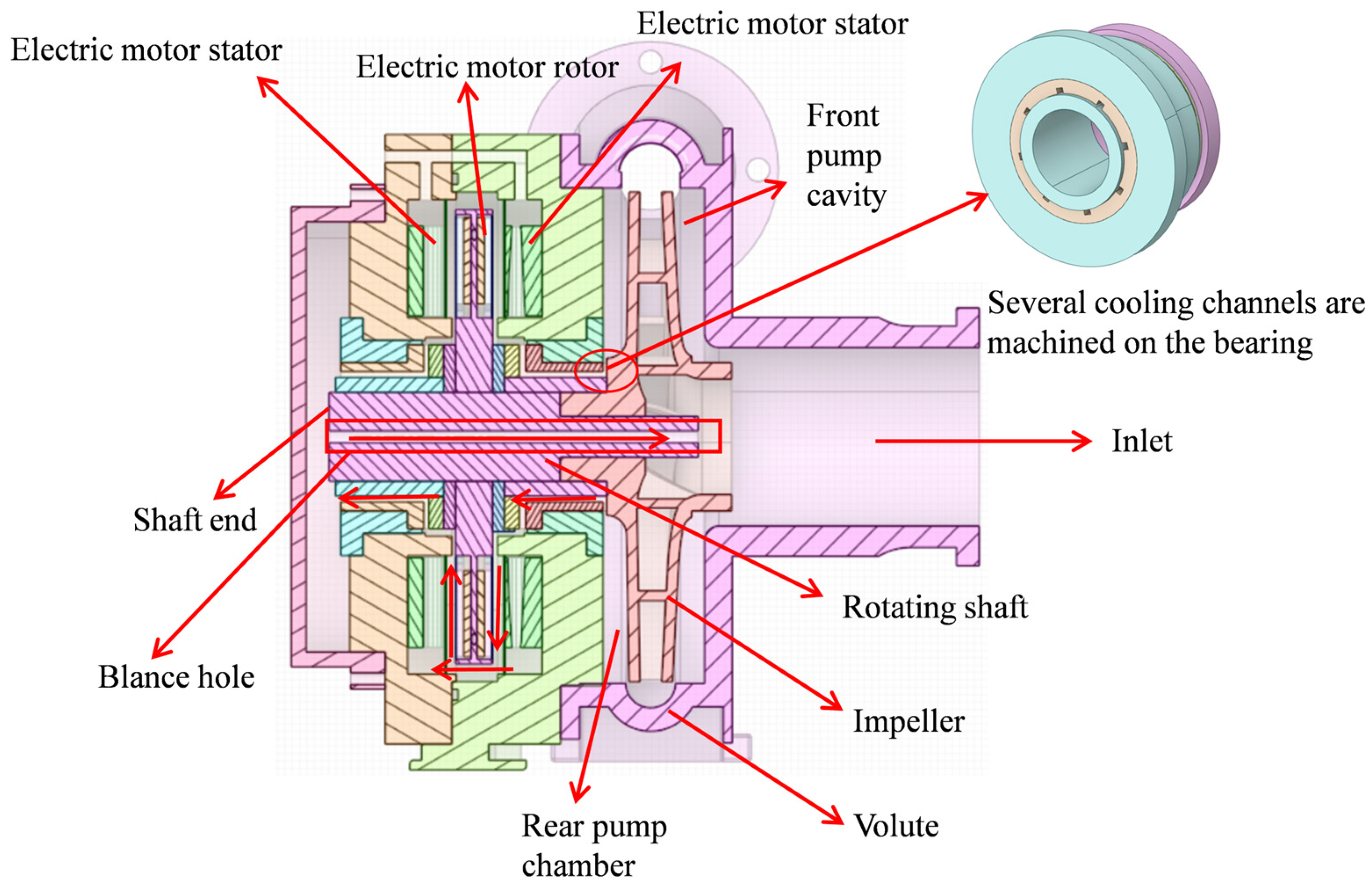
The disk-type electromagnetic direct-drive centrifugal pump adopts an integrated design of the motor and pump body, with the impeller coaxially connected to the disk-type drive motor rotor, forming a highly compact structure [30]. The core difference compared to existing integrated motor centrifugal pumps lies in the fact that we emphasize that while both use integrated motors, the disk-type electromagnetic direct-drive centrifugal pump has a unique hollow shaft return cooling path. The motor air gap creates the requirement that pumped fluid flow through for cooling, and the cooling fluid passing through the air gap needs to return to the suction end via balance holes on the shaft to form a circulating flow. The axial force is not only affected by the pressure difference between the front and rear pump chambers but also additionally influenced by the pressure difference across the motor air gap, as shown in Figure 1. Therefore, the flow characteristics in the air gap and their impacts on axial force cannot be ignored; thereby, inappropriate balance hole structures can lead to significant flow path losses and axial force, and exacerbating their adverse effects on the pump’s hydraulic performance and reliability. Based on this, this paper investigates the influence of different balance hole structures on the axial-force balance performance in a disk-type electromagnetic direct-drive centrifugal pump.
This paper investigates the influence of different balance hole structures on the axial-force balance performance in a disk-type electromagnetic direct-drive centrifugal pump. Unlike previous studies that primarily focused on standard centrifugal pumps or a limited set of balance-hole configurations, this work systematically explores multiple geometries, including those of variable diameter and variable length, and diverging holes. Optimizing the balance hole structure to simultaneously reduce axial force and minimize hydraulic losses has been identified as a critical factor for enhancing the overall performance of disk-type electromagnetic direct-drive pumps. The purpose of this paper is to study the effects of different balance hole structures on the axial force and hydraulic performance of electromagnetic direct-drive centrifugal pumps through numerical simulation, in order to provide practical guidance for the optimal design of this type of pump.

2. Numerical Modelling and Meshing

2.1. Numerical Calculation Model

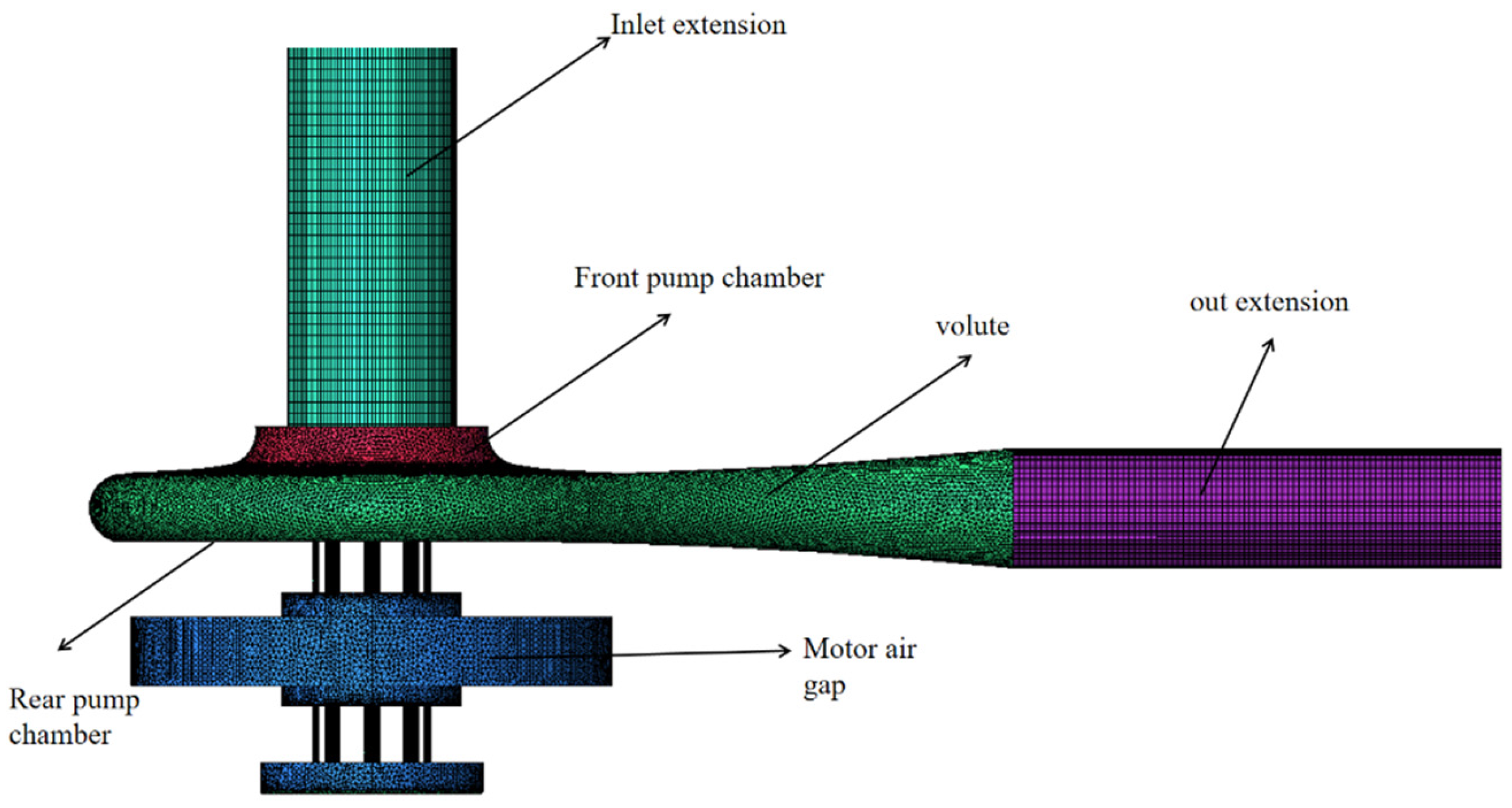
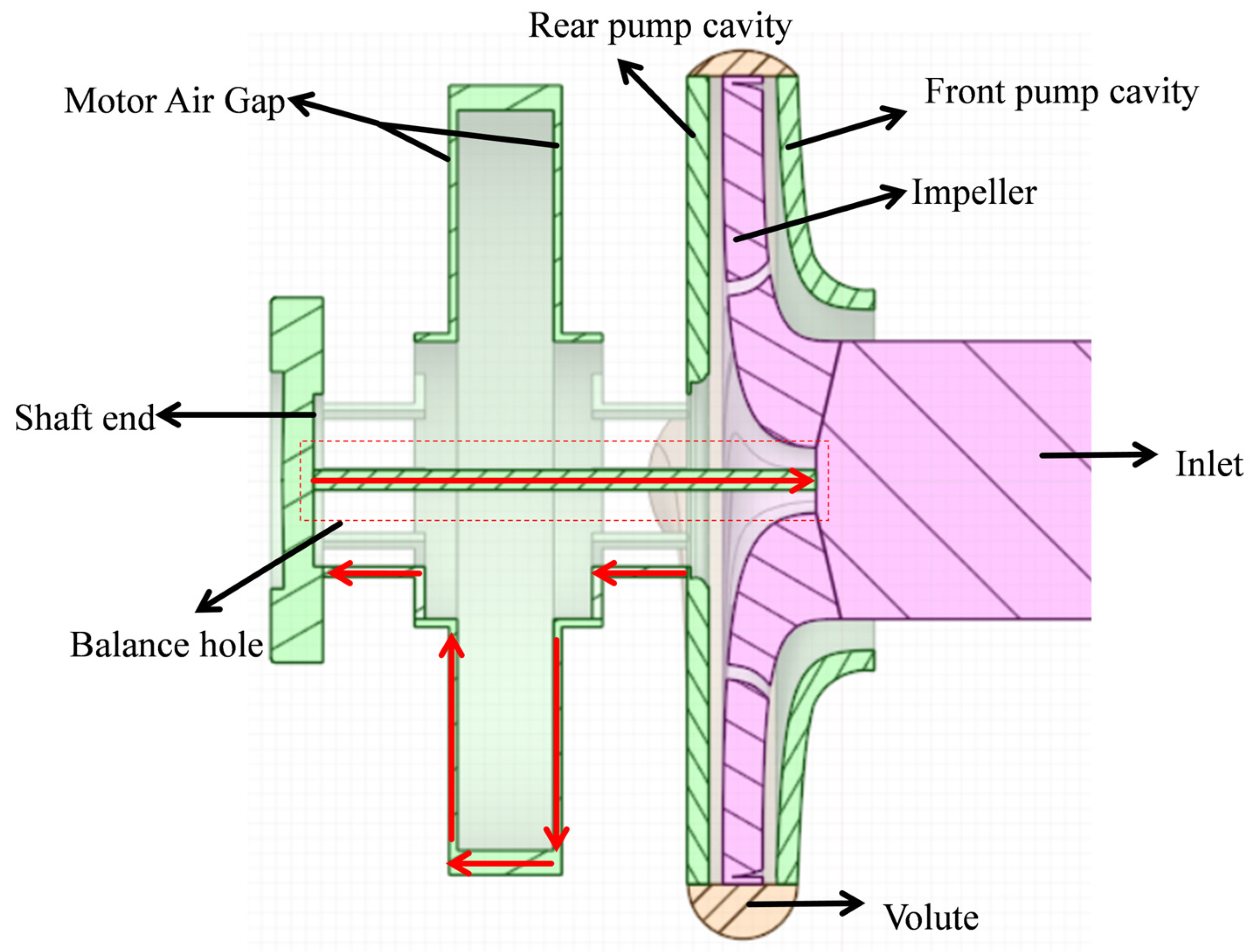
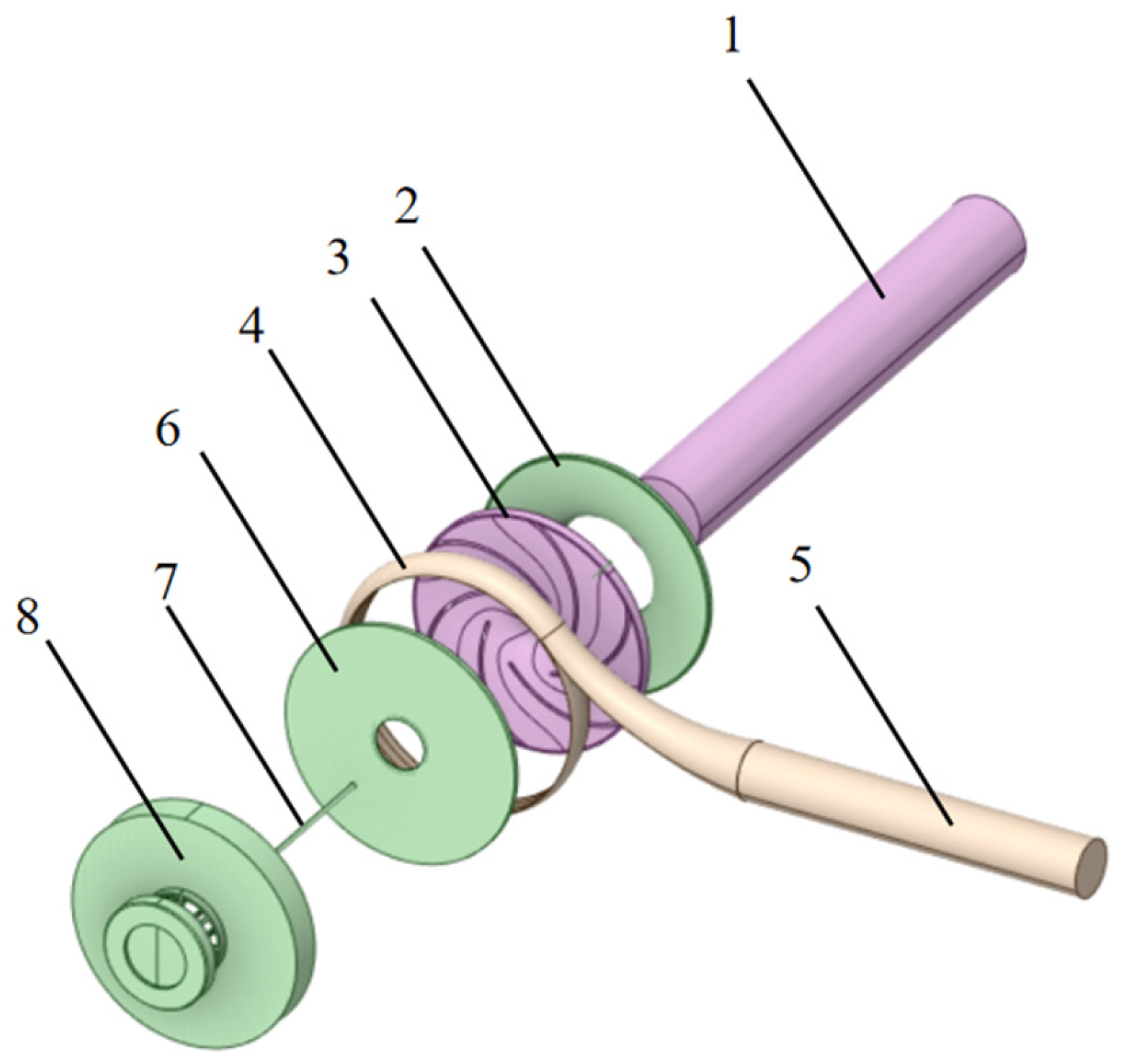
In this paper, an IS50-32-160 single-stage single-suction centrifugal pump is taken as the model, which was designed and manufactured by our research team at Wuhan University of Technology. The disk electromagnetic direct-drive centrifugal pump will be integrated with the motor and pump with the use of sliding bearings to support the main shaft, and open a number of cooling channels on the bearing; the pumped liquid through the bearing channels in and out of the motor air gap, and then through the balance hole back to the impeller inlet, the specific flow path shown in Figure 2. In comparisons with the traditional centrifugal-pump fluid model, there is a need to consider the impact of the motor air gap on the hydraulic performance of the pump group. The balance hole studied in this paper is opened on the shaft, so that the coolant flowing through the motor air gap can flow back to the suction port, forming a circulation loop. In this paper, the water body model is modelled in accordance with the three-dimensional model of the disc electromagnetic direct-drive centrifugal pump, including the inlet extension, the outlet extension, the volute, the impeller, the front pump chamber, the rear pump chamber, the motor air gap, and the balance holes, as shown in Figure 3. Its basic parameters are shown in Table 1. Q is flow rate, n is rotational speed, H is head, Z is number of blades, D is impeller diameter, B is impeller outlet width, D1 is impeller inlet diameter, ns is specific speed, and P is power.
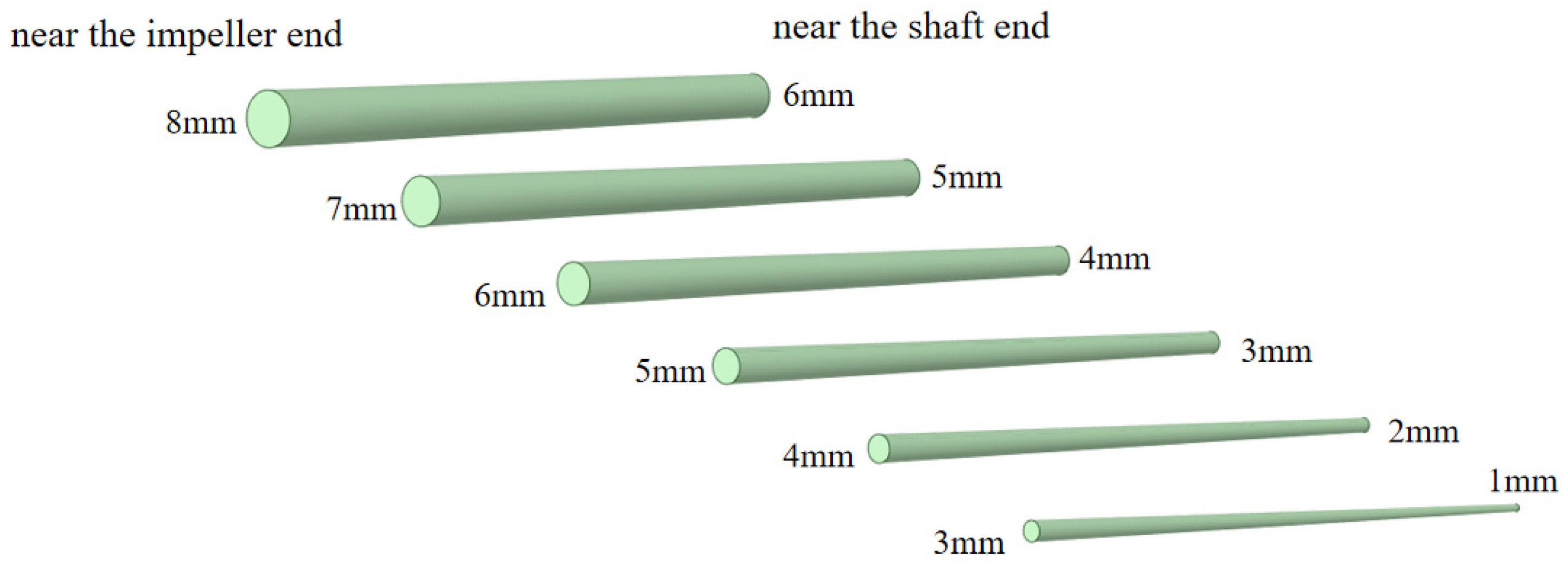
In this study, the optimisation of the design of the balance hole structure for the disc-type direct-drive centrifugal pump is carried out, and three types, with a total of 24 balance hole structures, are selected for comparative analysis, as shown in Table 2. A diameter of 0 mm indicates that the rotating shaft has no balance hole. This case serves as a baseline for comparison in order to evaluate the effects of different balance hole sizes on axial force and hydraulic performance. The first type is a fixed length of 100 mm, diameter 0–8 mm equal diameter balance holes; the second type is a fixed diameter of 4 mm, length 100–84 mm equal diameter variable length balance holes. The 4 mm diameter was chosen as a typical baseline from the literature and preliminary trials, while the 100 mm length represents the maximum available axial space. The third type has a length of 100 mm, and the diameter has a linear increase along the end of the shaft to the direction of the impeller, a linear change in the diverging balance holes. The gradient ranges were set to systematically study the transitions between diameters, ranging, from smaller to larger, from the 4 mm baseline and covering key intervals identified in the first type. The model of the diverging-type balance holes is shown in Figure 4.

2.2. Mesh Division and Irrelevance Test

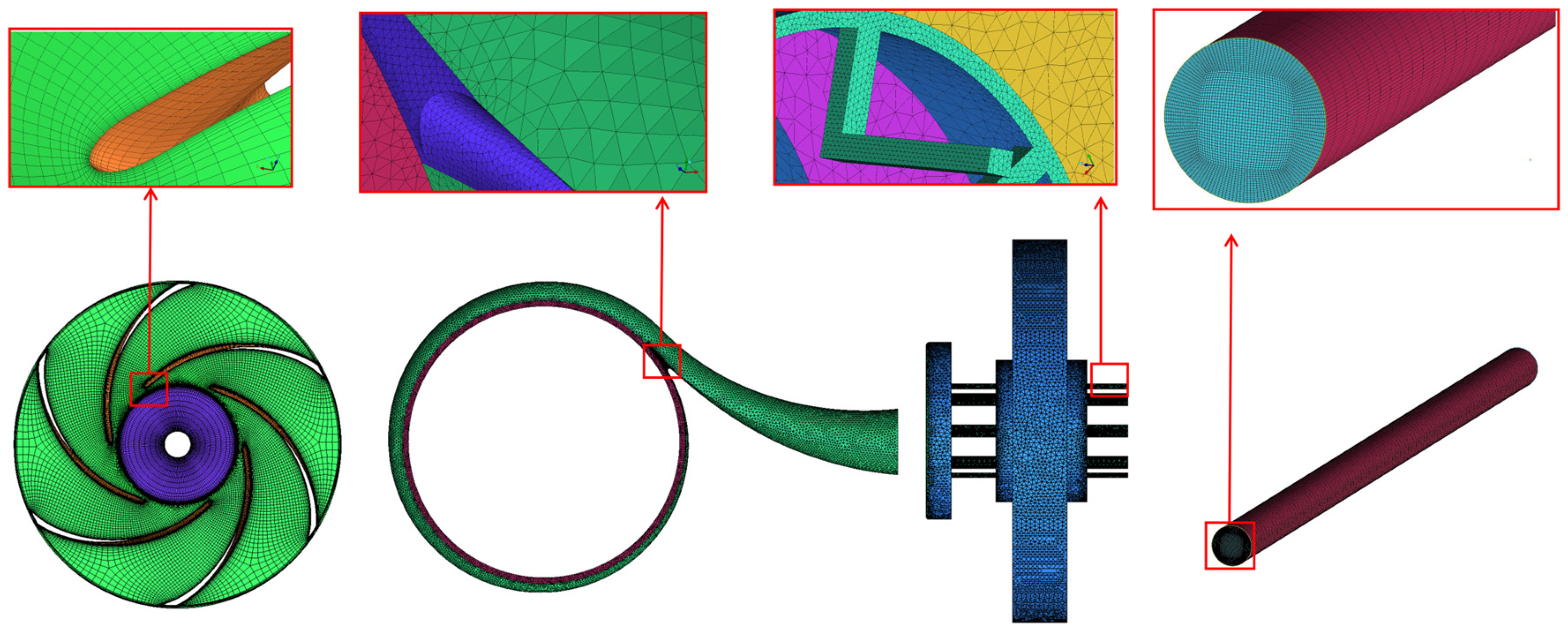
In this study, ANSYS-ICEM software is used to mesh the three-dimensional water body model of the centrifugal pump, because the inlet extension section, outlet extension section, impeller shape and balance hole are more regular, so the structured mesh is used for division. For the more complex shapes of the front pump chamber, rear pump chamber, volute and motor air gap, an unstructured mesh division is used. To ensure the resolution of flow in critical regions, local refinement was applied to key areas such as the interface between the impeller and the volute, the motor air gap, the bearing cooling channels, and the shaft holes. After this treatment, the quality metrics of all final mesh cells were better than 0.4, meeting the requirements for CFD simulations. Figure 5 and Figure 6 show the mesh structure of the electromagnetic direct-drive centrifugal pump and the detailed mesh of its key components, with the specific mesh element count for each part provided in Table 3. Meanwhile, in order to avoid the problems of poor simulation accuracy caused by insufficient grid numbers and the waste of computational resources caused by too-large grid numbers, this paper firstly conducts grid-independence analysis on the selected grids before the formal simulation, in order to balance the conflict between computational accuracy and computational resources, and make the computation more reasonable.
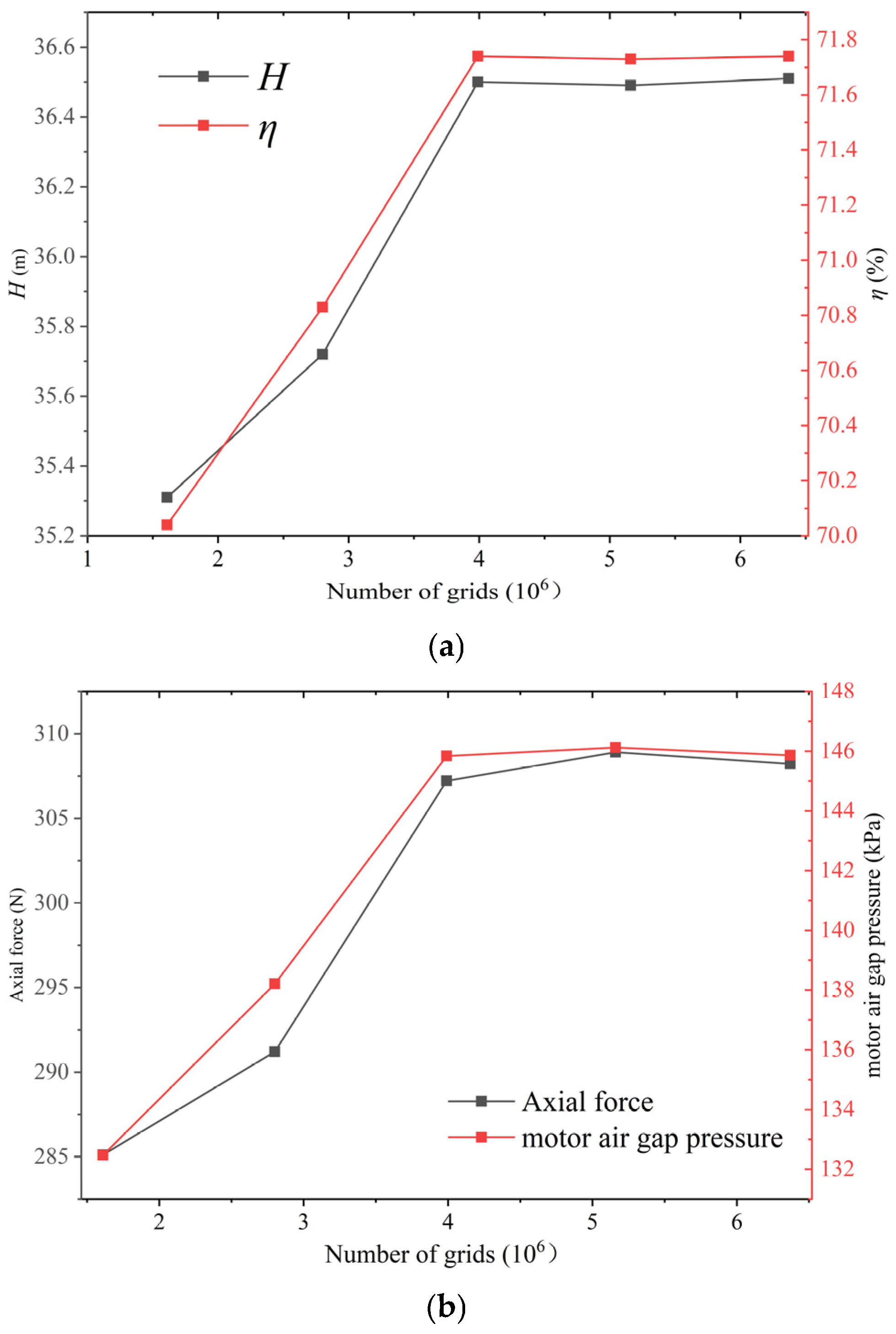
The balance hole with a 4 mm diameter and 100 mm length was selected for grid independence verification, as its geometric parameters lie in the mid-range of the study and it can effectively represent the mesh characteristics of typical balance hole configurations. A grid independence analysis of the head was conducted for this model pump under the conditions of Q = 12.5 m3h−1 and a speed of n = 2900 rpm. The curves of calculated head and efficiency versus the number of grids are shown in Figure 7a, and the curves of calculated axial force and motor air-gap pressure versus the number of grids are shown in Figure 7b. It can be seen that when the number of grids reaches 3.99 × 10⁶, the calculated results have effectively converged, and further grid refinement would not significantly change the calculated values of head, efficiency, axial force, and motor air-gap pressure. Therefore, in order to minimise the number of grids to avoid the waste of computational resources and to ensure the accuracy of the calculation, a number of grids of 3.99 × 10⁶ is finally selected for the subsequent simulation of the original model. For other models with different balance hole configurations, the total number of grids for subsequent simulations varies within a range of ±3000.

3. Numerical Calculation Method and Boundary Condition Setting

The Governing Equations

The internal flow in a centrifugal pump is a three-dimensional, viscous, unsteady turbulent flow, and its motion follows the Navier–Stokes equations. Since the heat exchange in a centrifugal pump is negligible, the energy conservation equation can be disregarded. Thus, only the mass and momentum equations need to be solved simultaneously.
Mass conservation equation:
ρ t + ( ρ u i ) x i = 0
Momentum conservation equation:
t ( ρ u i ) + x j ( ρ u i u j ) = p x i + x j [ μ u i x j ρ u i u j ] + S i
where ρ is the density of the mixture, u is the velocity, p is the pressure, t is the time, x is the spatial coordinates, μ is the dynamic viscosity, and S is the source term in the momentum equation, representing body forces acting on the fluid.
To close the Reynolds-averaged Navier–Stokes (RANS) equations for solving the three-dimensional turbulent flow, a turbulence model must be introduced. In practical engineering, the RNG k-ε model, standard k-ε model, and SST k-ω model are the most widely applied. Compared to the RNG k-ε model and the SST k-ω model, the standard k-ε model is characterized by its broad applicability, high generality, and strong accuracy [31]. Extensive experimental and research efforts by a large number of experts and scholars have demonstrated its particular suitability for solving the internal flow fields of turbomachinery with strong rotation and flow separation tendencies. Therefore, in this study, the standard k-ε turbulence model within the two-equation framework is adopted in Fluent as the numerical solver for calculating the internal flow field and axial force of the centrifugal pump.
The standard k-ε model is employed to close the Reynolds-averaged equations, with the k-equation given by:
( ρ k ) t + ( ρ k u i ) x i = x j μ + μ t σ k k x j + G k ρ ε
The ε-equation is expressed as
( ρ ε ) t + ( ρ ε u i ) x i = x j μ + μ t σ ε ε x j + C 1 ε ε k G k C 2 ε ρ ε 2 k
where Gk is the generation term of turbulent kinetic energy k due to mean velocity gradients, C1ε, C2ε, and C3ε are empirical constants, σk and σε are the turbulent Prandtl numbers for k and ε, respectively, and μt is the turbulent viscosity.
μ t = ρ C μ k 2 ε
where Cμ is empirical constant. All symbols used in the above equations are described in the nomenclature.
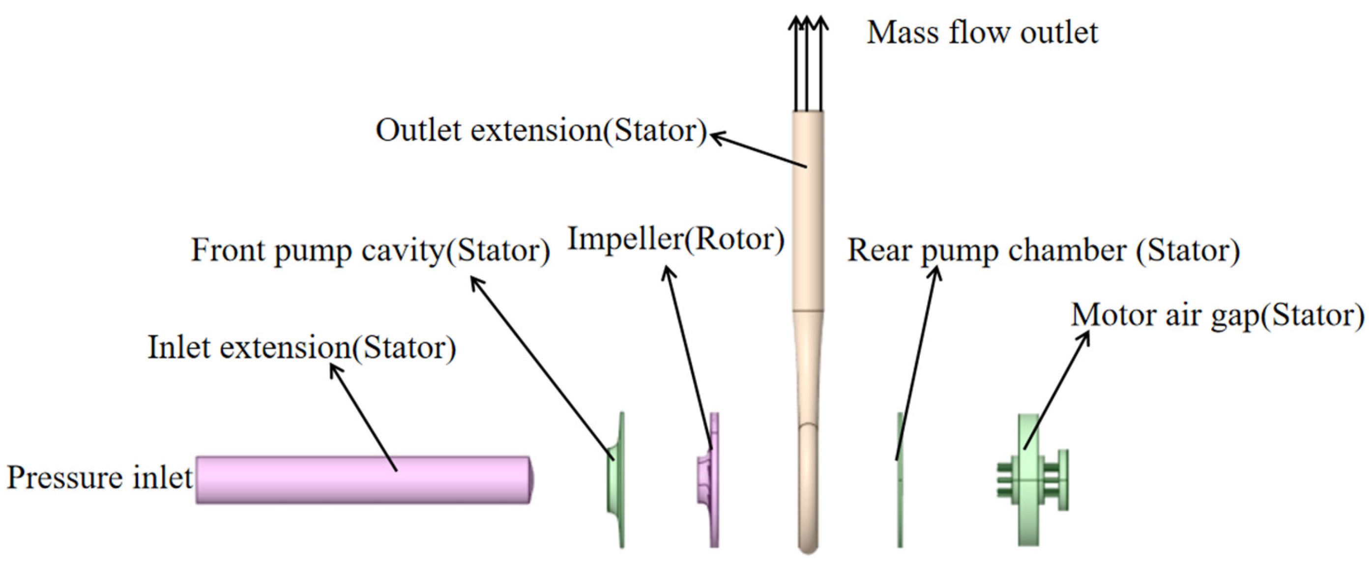
In this study, the turbulence model selects the standard k-ε model, the pressure inlet boundary condition is used in the inlet of the computational domain, and the outlet boundary condition is set as the mass flow outlet. The impeller, the balance hole, the front pump chamber, the rear pump chamber near the impeller, the end of the shaft, and the rotor surface of the motor air gap are all defined as rotating wall surfaces; the rotation speed is set to 2900 rpm; and the rotating axis is the geometrical centre of the impeller of the centrifugal pump. The coupling surface between each computational domain is defined as an Interface, and a slip mesh is used to achieve wall rotation. In order to ensure numerical calculation accuracy, the velocity–pressure coupling iteration solution adopts the SIMPLEC method, and the discretisation of the momentum equation, as well as the turbulent kinetic energy and dissipation rate transport equations, are all in the second-order upwind scheme. The convergence criterion is set to a value of 10−5. In the simulation, the rated flow rate of the electromagnetic direct-drive centrifugal pump is 12.5 m3 h−1 and the fluid density is equal to 998.21 kg m−3. The boundary conditions are shown in Table 4 and Figure 8.
The numerical methodology framework employed in this study—including wall treatment, boundary condition definitions, interface settings, and solver configuration—is consistent with that used in our previous validation study on a 37 kW electromagnetic direct-drive self-priming pump model [32], which was carefully validated against experimental data to ensure its reliability. Although different turbulence models were adopted due to specific pump type variations, the overall numerical solution strategy and boundary condition treatment methods remain consistent. This methodological continuity provides a solid foundation for the accuracy of the results presented in this work.

4. Analysis of Results

4.1. Influence of the Characteristic Parameters of the Equilibrium Hole on the Pressure Distribution of the Flow Field in the Air Gap of the Motor

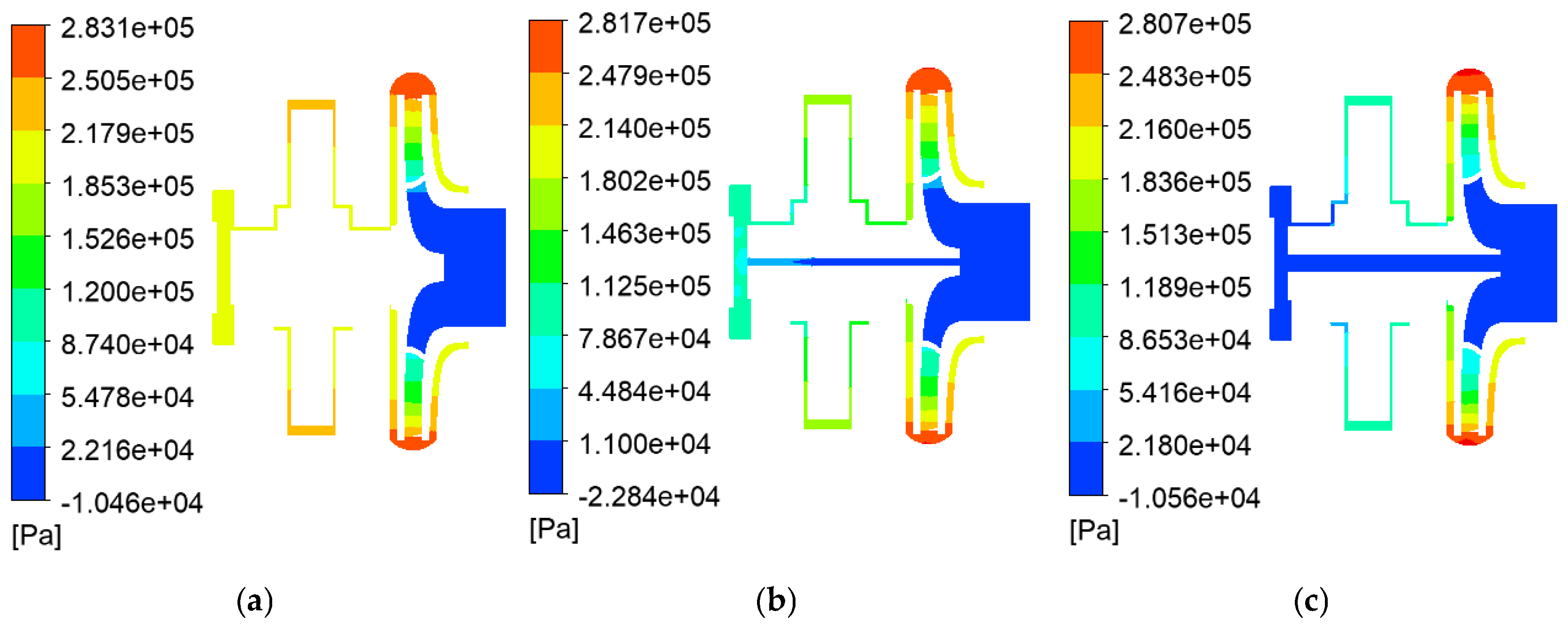
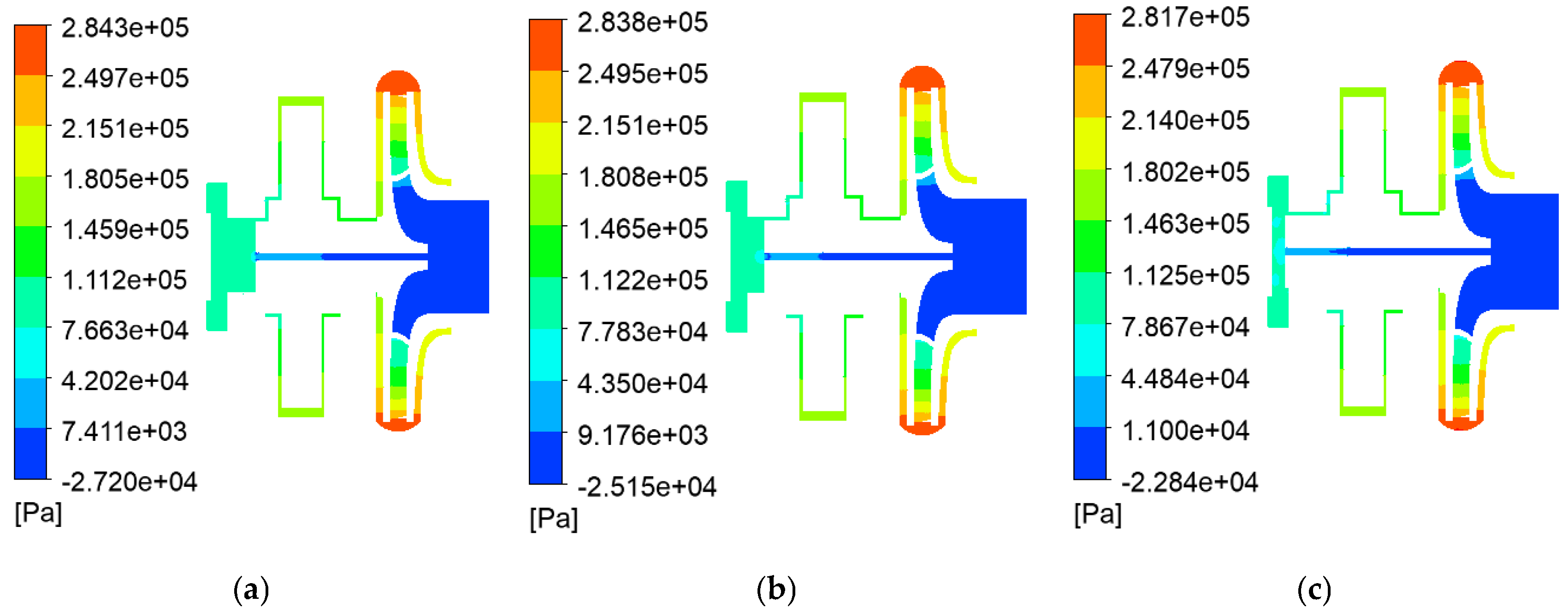
Electromagnetic direct-drive centrifugal pumps, compared to ordinary centrifugal pumps, need to take into account the additional impact of the motor air gap. In order to analyse the impact of the balance hole on the motor air gap, the electromagnetic direct-drive centrifugal-pump xy profile motor air gap pressure maps are plotted for different balance hole structures. In this paper, the following representative models are selected for the pressure cloud analysis: variable diameter balance holes (0 mm, 4 mm, 8 mm), equal diameter variable length balance holes (100 mm, 92 mm, 84 mm) and diverging balance hole (1–3 mm, 4–6 mm, 6–8 mm).
Figure 9 reveals the influence law of the balance hole diameter parameter on the electromagnetic direct-drive centrifugal pump. When the length of the balance hole is fixed, an increase in diameter significantly increases the leakage flow of fluid through the balance hole, thus resulting in a significant decrease in the motor air gap pressure at the rear pump chamber and shaft end. When the diameter of the balance hole is increased from 0 mm to 8 mm, the pressure in the air gap of the motor decreases from 216.18 kPa to 91.02 kPa and the pressure in rear pump chamber decreases from 221.32 kPa to 210.61 kPa. Previous numerical and experimental studies on centrifugal and magnetic drive pumps have consistently shown that the presence and size of balance holes can effectively reduce the pressure in the rear pump chamber [33,34]. The underlying mechanism is similarly attributed to increased leakage flow, which alleviates local pressure buildup and improves the flow distribution in pump cavities. The trend observed in this work—larger hole diameters leading to lower rear chamber and shaft-end pressures—is thus consistent with the existing studies. It is also noted that the air-gap pressure along the inflow direction exhibits an initial increase followed by a decrease. This behaviour is primarily attributed to the centrifugal acceleration experienced by the fluid near the rotor side, which converts part of the fluid’s kinetic energy into static pressure, leading to a local pressure rise as the fluid progresses axially toward the shaft end.
Figure 10 presents the pressure contour plots of the flow field after varying the balance hole length. The length variation primarily exerts a minor influence on the leakage flow rate through frictional losses along the passage. However, the contribution of frictional losses to the total pressure drop is significantly smaller than the localized resistance changes induced by diameter variations. Consequently, length adjustments only result in slight pressure fluctuations. When the balance hole length increases from 84 mm to 100 mm, the pressure in the motor air gap merely decreases from 140.85 kPa to 139.65 kPa.
For the diverging balance holes, as seen in Figure 11, the diameter of the orifice changes gradually along the axial direction, avoiding flow separation and eddy currents triggered by a sudden change in the orifice diameter, and reducing the local energy loss. This gradual change in design results in a smoother transition of the pressure distribution from the high-pressure region to the low-pressure region, with pressure values between those of the variable diameter balancing orifices corresponding to the largest and smallest orifice diameters.
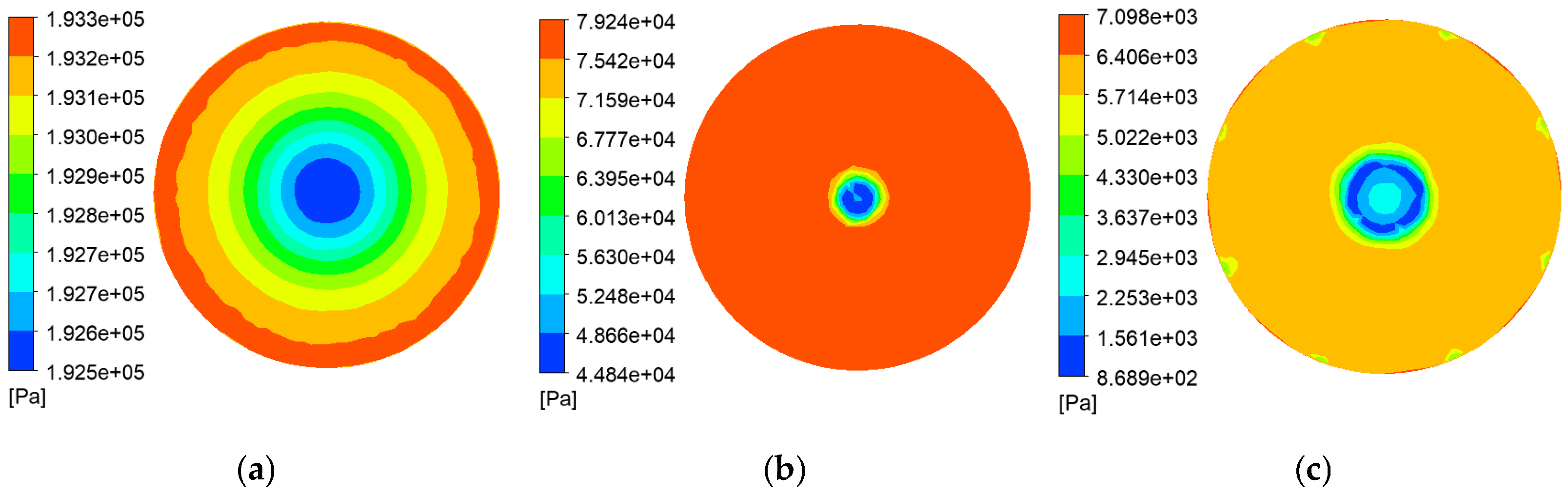
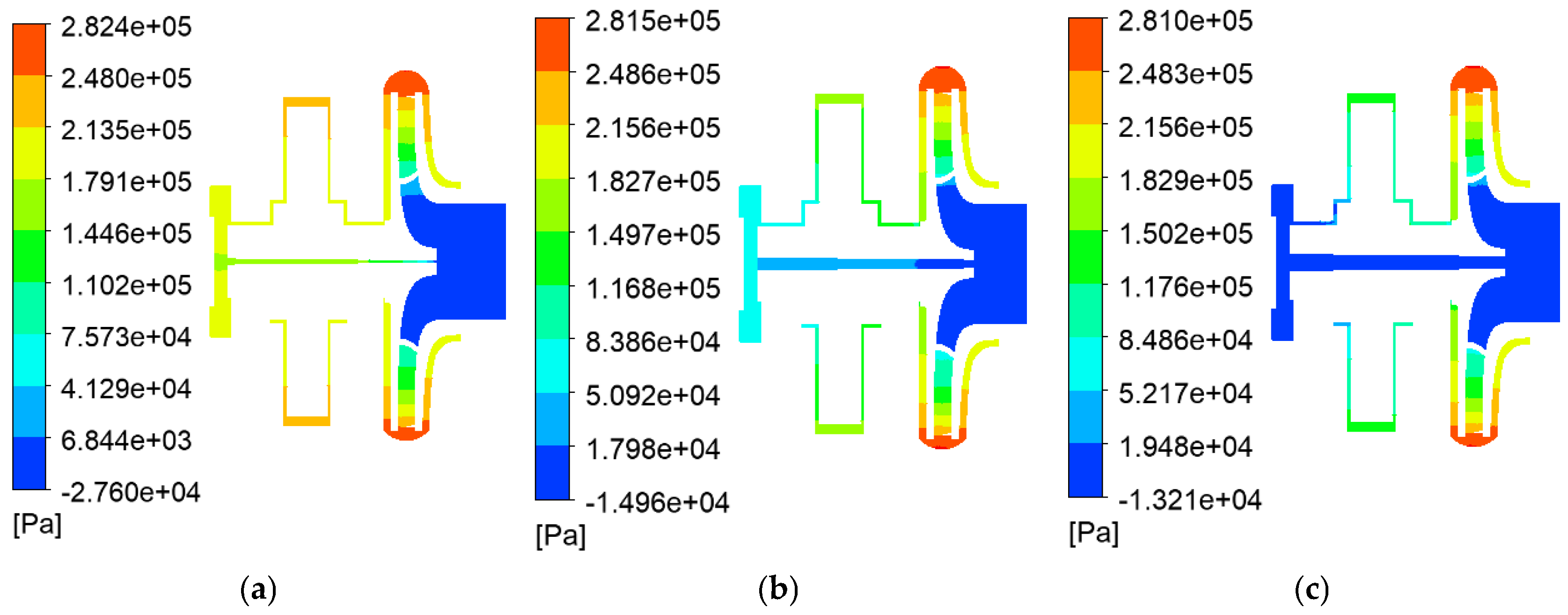
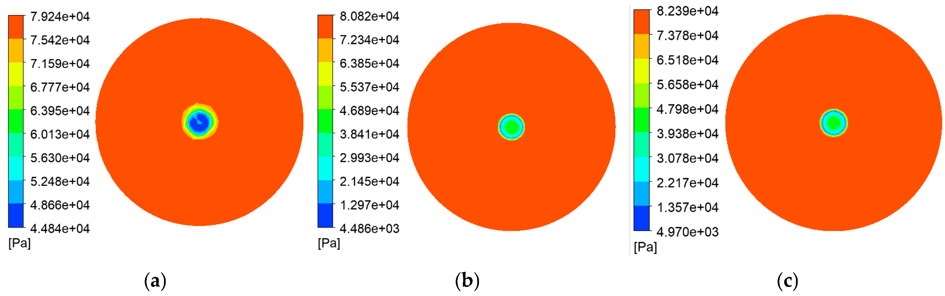
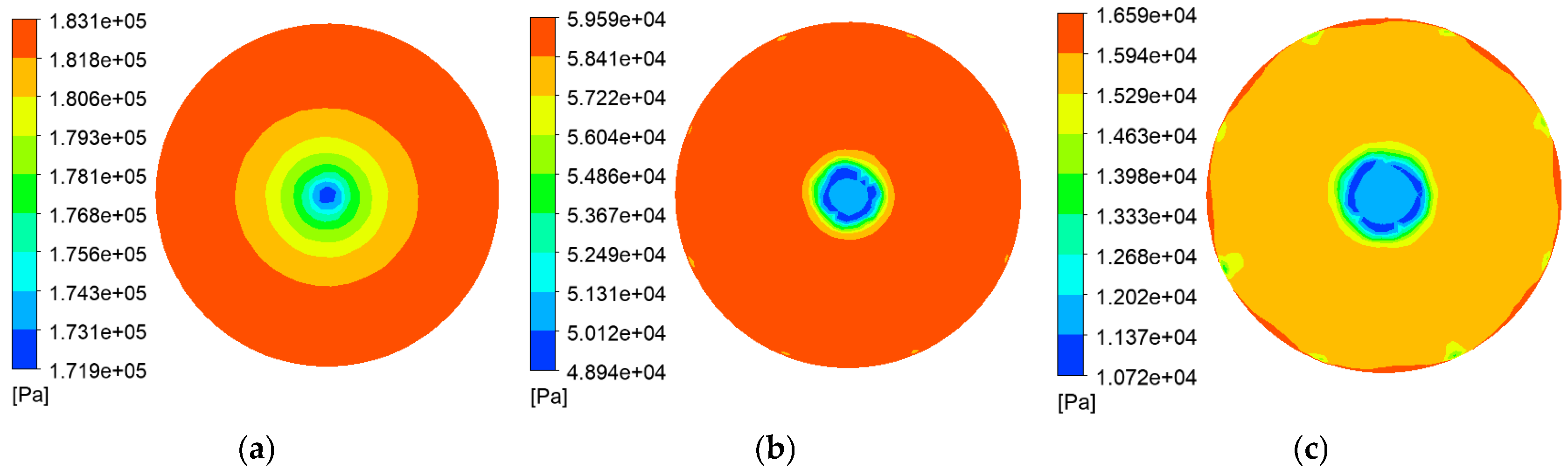
The balance holes directly connect the fluid at the shaft end with the impeller. Since both the magnitude and distribution of pressure at the shaft end have a significant influence on rotor axial force, the investigation of pressure distribution primarily focuses on the shaft end surface. Figure 12, Figure 13 and Figure 14 present the wall pressure contour plots at the shaft end of the electromagnetic direct-drive centrifugal pump under rated operating conditions, featuring different balance hole configurations.
As can be seen from Figure 12, under the rated flow conditions, when there is no balance hole, the fluid only flows through the air gap of the motor, and due to the narrow air-gap flow channel, the flow is restricted; the pressure at the end of the shaft surface along the radial direction from the inside to the outside gradually increases, but the differential pressure change is not significant; it shows a stepwise distribution. After the addition of balance holes in the end of the shaft surface, radius R1 is less than the balance hole radius R2 region; the existence of balance holes introduced leakage flow near the centre of the region (R1 ≤ R2) due to the accelerated outflow of fluids, and the pressure drops abruptly. As the radial distance increases relative to the radius of the balance hole, the leakage flow decreases and the pressure rises. When R1 > R2, this area is far away from the influence of the balance hole, and the leakage flow tends to stabilise and the pressure distribution is uniform. However, as the diameter increases, the flow rate of the eight slots increases, resulting in a high pressure–low pressure zone at the edges corresponding to the location of the slots. This is due to the fact that, as the diameter of the balance hole increases, the flow rate of the grooves in the bearing increases, thus affecting the pressure at the end face of the shaft.
From Figure 12, it can be determined that when the diameter is fixed at 4 mm, the shortening of the length from 100 mm to 84 mm only causes a slight increase in the pressure at the end of the shaft, the pressure gradient in the near-axis region (R1 ≤ R2) remains basically unchanged, and the distribution of the pressure in the far-axis region (R1 > R2) is relatively uniform, which indicates that the effect of the length of the balance hole on the end pressure is relatively limited. This indicates that the influence of the length of the balance hole on the pressure at the end of the shaft is relatively limited.
In contrast, Figure 14 shows that the diverging balance holes, due to the gradual change of hole diameter, show a smoother pressure gradient in the near-axis region (R1 ≤ R2), effectively avoiding the pressure drop caused by the sudden change of the flow; in the far-axis region (R1 > R2), the pressure distribution is in the range of the smallest and the largest holes corresponding to the equal-diameter balance holes, which is more stable on the whole. This comparison shows that the diverging balance hole is able to achieve a more stable pressure distribution at the end of the shaft, which is important for reducing flow losses and improving the stability of pump operation.
Overall, the pressure at the shaft end decreases significantly with increasing counterbalance hole diameter, but decreasing length causes only a slight increase in pressure, indicating that counterbalance hole diameter is the main factor affecting pressure.
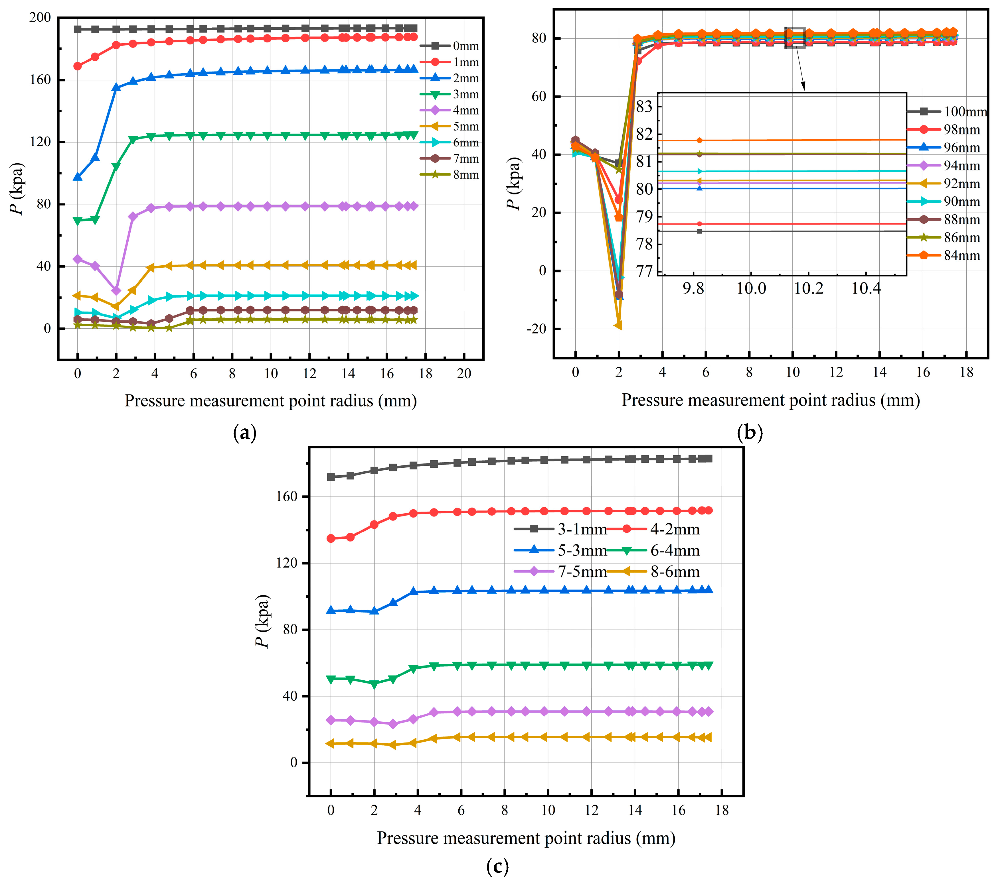
In order to perform further quantitative analysis of the pressure distribution relative to the changes in the balance hole structure, Figure 15 shows all the balance hole models. Assume the rated flow rate, and that the liquid flows in the direction of the end of the shaft surface 0°, 90°, 180 °, 270° from the centre of the shaft. At different locations, determine the pressure value, and take the average value as the radial position of the pressure value, and then plot along the radial distribution of the pressure curve. Then, plot the change curve of pressure distribution along the radial direction.
Figure 15a shows that when the balance hole length is constant, and when the diameter ≤ 3 mm, the smaller leakage flow makes the pressure along the radial direction of the first rapidly rise and then slow down. At a diameter > 3 mm, the leakage flow increases significantly, and the formation of throttling in the near-axis region of the low pressure is evident, so the pressure distribution presents a “falling–rising–stable” three-stage characteristic. The diverging balance hole extending through the aperture gradient design effectively reduces the flow separation and vortex, so that the pressure transition is smoother and more stable. Under the same diameter condition, increasing the length of the balance hole will slightly reduce this effect due to the increase in leakage, but the influence of this factor is much smaller than the effect of the diameter parameter respect to the end of the shaft.

4.2. Influence of Balance Hole Characteristic Parameters on Axial Force of Centrifugal Pumps

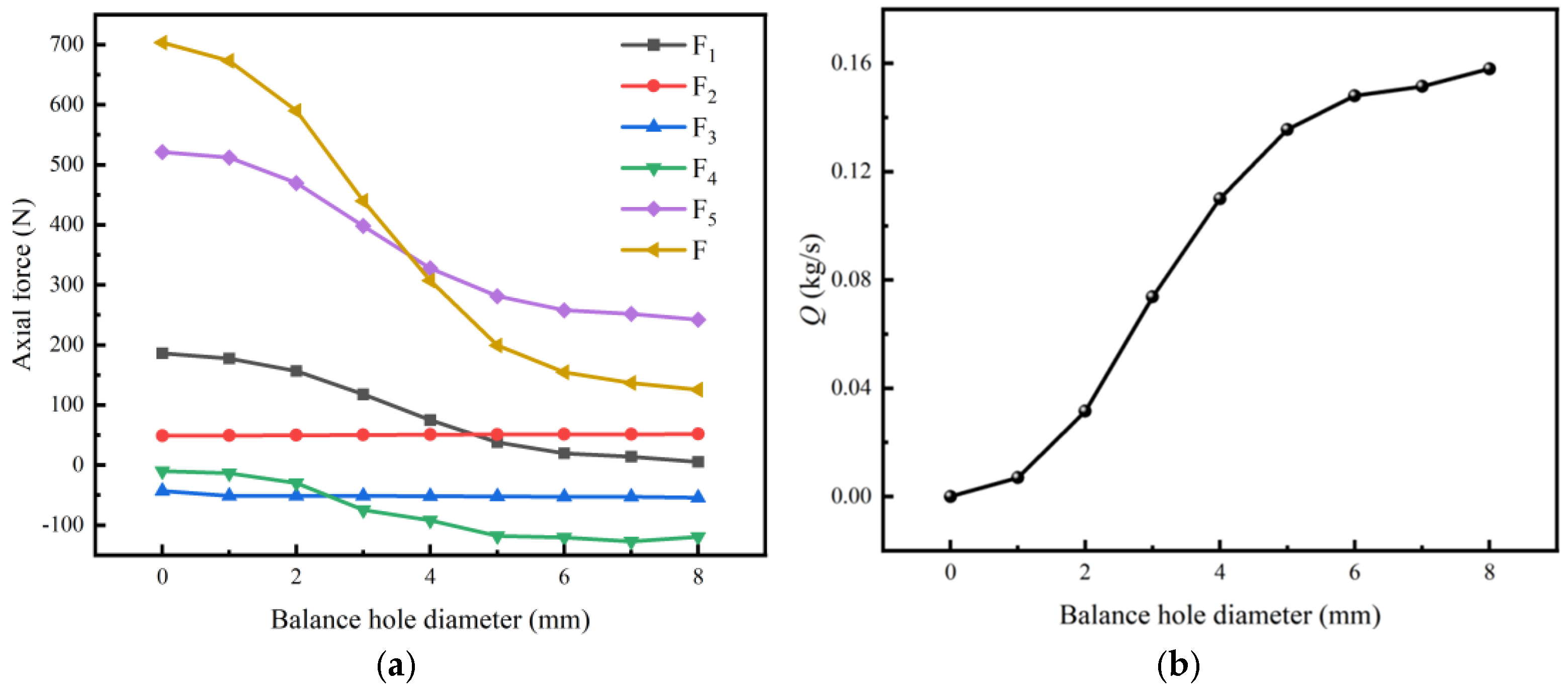
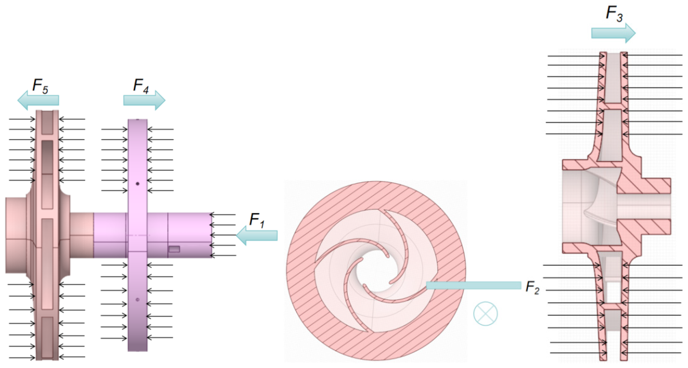
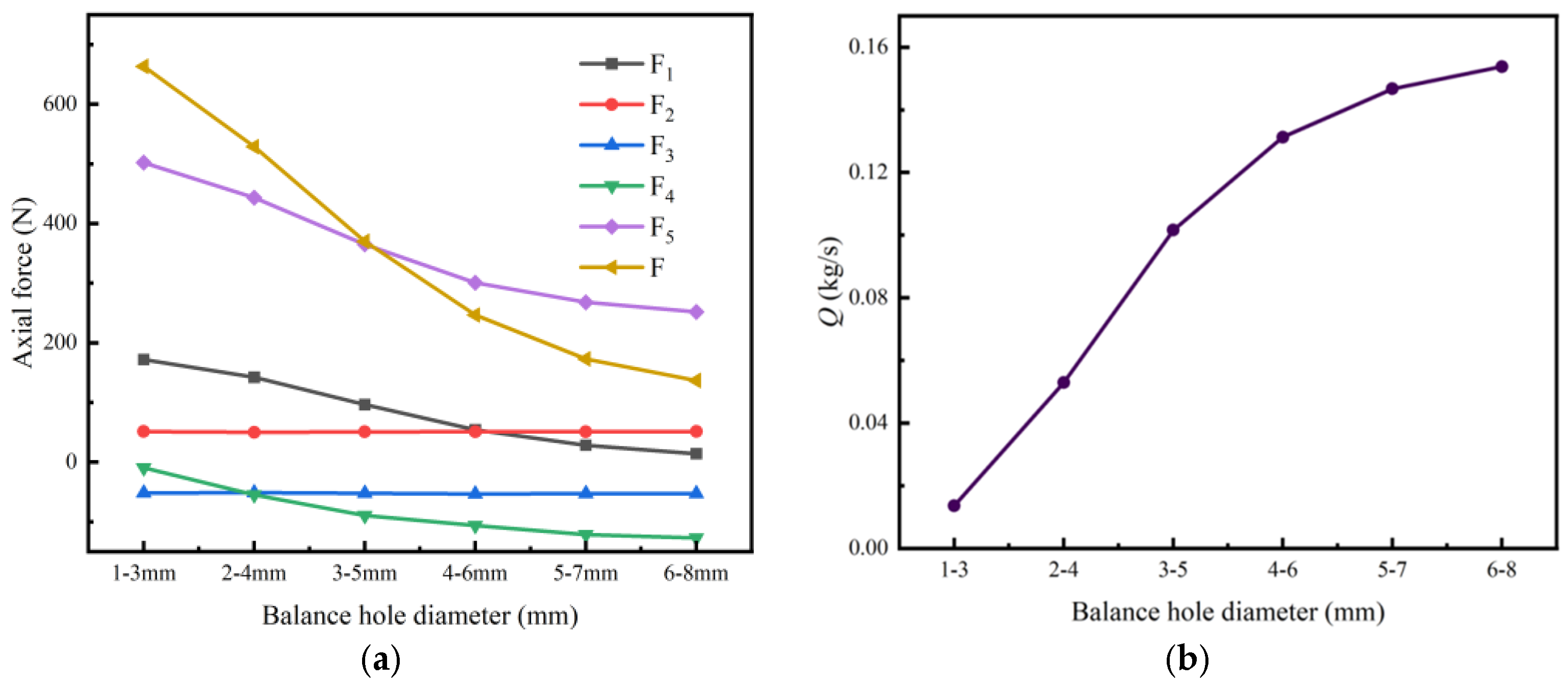
Given the structural characteristics of the electromagnetic direct-drive centrifugal pump reviewed in this paper, the total axial force F, representing the sum of all axial forces in the pump, mainly consists of the axial force F1 at the end of the shaft, the axial force formed by the pressure difference between the working surface of the vane and the backside of the vane F2, the axial force acting on the front and back of the cover plate of the impeller axial force in the F3, and the air gap of the rotor of the motor F4, as well as the front and back of the pump chamber axial force F5, as shown in Figure 16. In the present analysis, the calculation results indicate the impeller inlet direction as the positive direction. Numerical simulation of electromagnetic direct-drive centrifugal pumps with different balance hole diameters was carried out by the Fluent software, and the axial force of each part was calculated separately; the total axial force of each model is summarised, and the specific results are shown in Figure 16, Figure 17 and Figure 18.
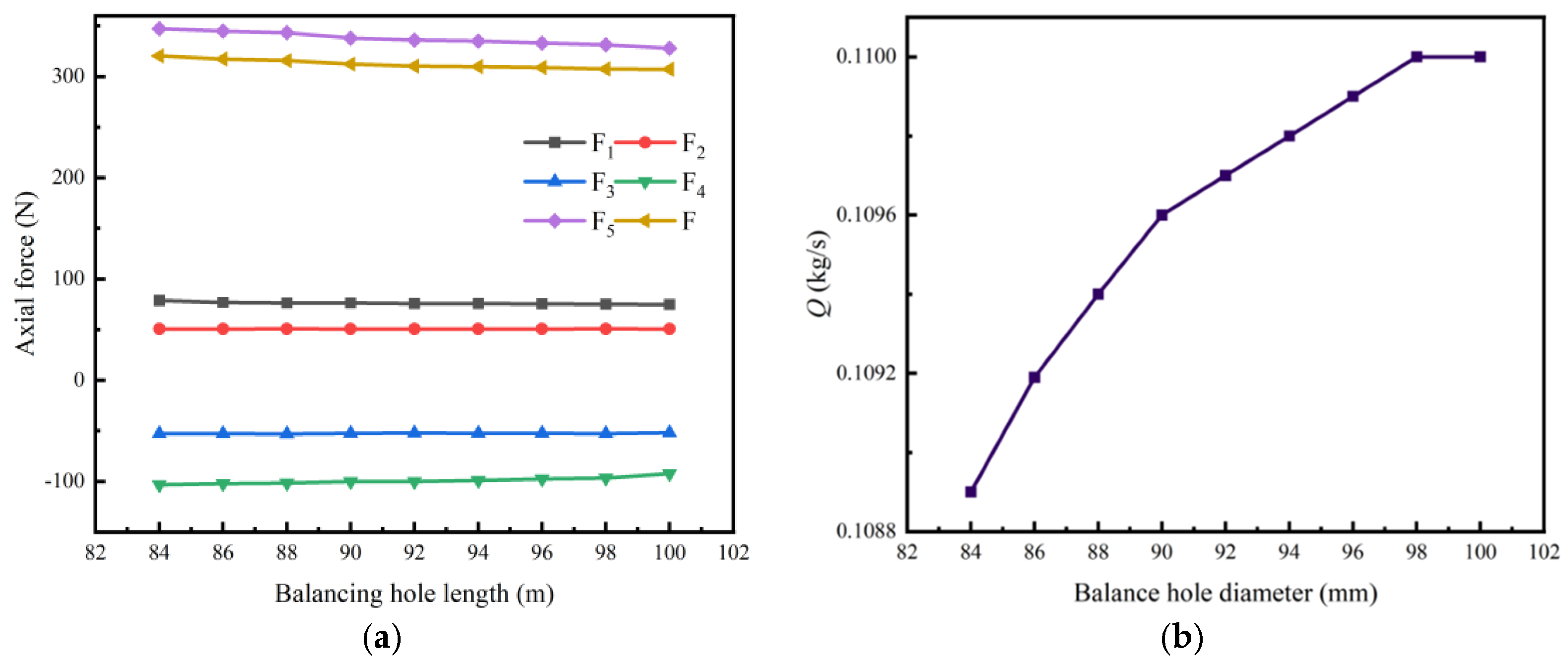
The analysis of the results shown in Figure 17, Figure 18 and Figure 19 shows that after the addition of balance holes, both the axial force on the shaft end (F1) and the axial forces in the front/rear pump chambers (F5) are significantly reduced, thereby effectively decreasing the total axial force. In contrast, variations in the balance hole diameter have only a minor influence on the axial-force components F2, F6, and F4, and their contribution to the overall change in total axial force is limited. Further examination of the total axial-force curve under the rated flow condition reveals that the total axial force is noticeably sensitive to the balance hole diameter, with the variation in total force primarily stemming from the pronounced changes in F1 and F5. Therefore, the axial forces on the shaft end face and in the front/rear pump chambers play a dominant role in the formation of the total axial force.
In Figure 17, the axial-force curve and the leakage curve can be seen; when the balance hole length is fixed, with larger diameters, the liquid flowing through the balance hole from the end of the high-pressure area to the impeller inlet side of the impeller inlet side of the leakage increases, thus balancing the axial force, so that the axial force is significantly reduced, but regardless of the size of the diameter of the balance hole, the axial force cannot be attenuated to 0, and with the increase in the diameter of the balance hole, the axial-force reduction is gradually reduced. When the diameter of the balance hole increases from 0 mm to 8 mm, the axial force decreases from 703.45 N to 125.57 N. When the diameter of the balance hole increases from 0 mm to 5 mm, the axial force decreases faster; diameters in the range of 3 mm to 5 mm show the most significant rates of decrease, with a total decrease of 54.7%. When the diameter is increased from 6 mm to 8 mm, the rate of reduction of axial force decreases significantly, although only from 154.6 N to 127.6 N.
Comparative analysis of Figure 17 and Figure 18 demonstrates that increasing length leads to higher leakage flow but lower axial force. Notably, diameter parameters affect axial force much more significantly than length parameters—when diameter remains constant, axial force only varies by 4.3 percent, from 307.2 N to 320.3 N, across the 84 mm to 100 mm length range.
From the axial-force curves in Figure 17 and Figure 19, it can be seen that when the length of the balance hole is fixed, the diverging balance hole reduces the axial force more gently with the increase of the hole diameter, compared with the equal diameter balance hole, because the gradual increase of the diverging balance hole diameter in the axial direction can achieve a more continuous and stable pressure distribution. Thus, when increasing the bore diameter, the diverging balance hole not only can effectively reduce the axial force, but also can prevent the pressure from changing sharply.

4.3. Balance Hole Characteristic Parameters Relative to the Pump Hydraulic Performance Analysis

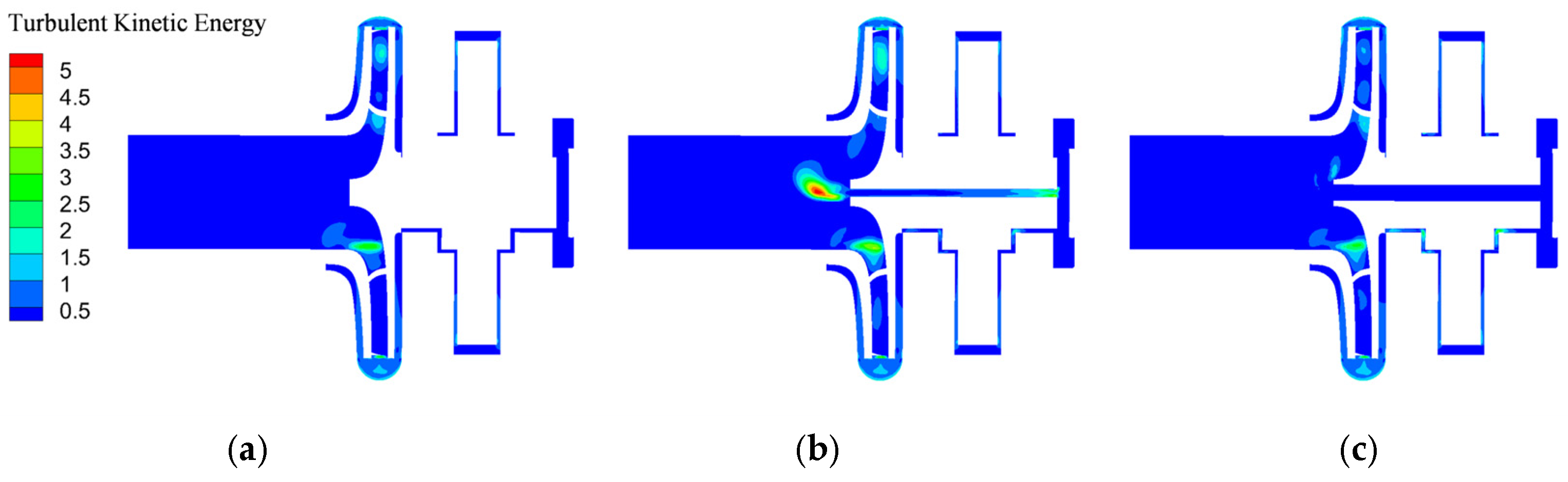
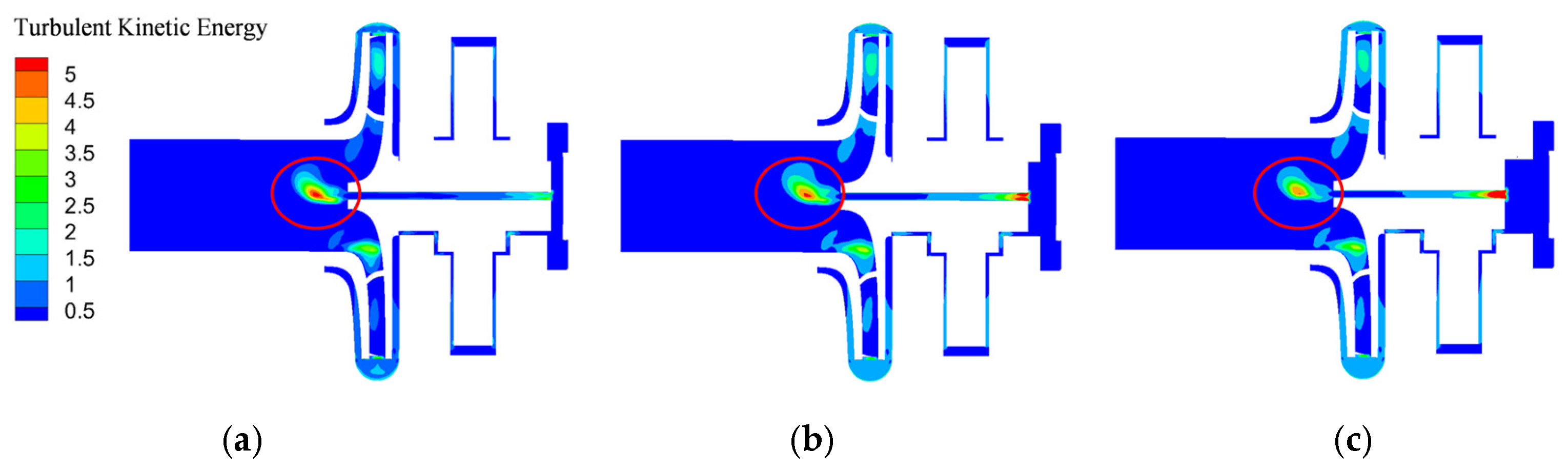
Turbulent kinetic energy is a physical quantity characterizing turbulence intensity. Therefore, investigating the variation of turbulent kinetic energy under different flow rate conditions can effectively reflect the interaction intensity between the backflow through the balance holes and the main flow upstream of the impeller inlet. As shown in Figure 20, the fluid returning through the balance holes directly impinges on the incoming flow at the impeller inlet, intensifying flow mixing and disrupting the originally stable flow structure in this region, thereby introducing additional hydraulic losses. When the balance hole diameter is d = 4 mm, the smaller hole size results in a higher local flow velocity through the hole. The resulting high-speed jet exerts a strong disturbance on the main flow at the impeller inlet.
As the balance hole diameter increases to 8 mm, the average velocity inside the hole decreases accordingly, leading to a weakened jet strength at the hole outlet. Consequently, the direct impingement of the backflow on the main flow near the impeller front shroud is alleviated, the amplitude of velocity fluctuations at the impeller inlet is reduced, and the overall turbulent kinetic energy level exhibits a decreasing trend. However, enlarging the balance hole diameter simultaneously causes a significant increase in the total leakage flow rate through the balance holes. Although the local turbulent kinetic energy is reduced, the accompanying increase in volumetric loss still has an adverse effect on the pump efficiency.
As shown in Figure 21, with a decrease in the balance hole length, while maintaining a constant hole diameter, the effective leakage passage inside the balance hole is shortened, resulting in a reduction in the actual leakage flow participating in the backflow. The decreased leakage flow leads to a lower average velocity of the backflow entering the impeller inlet region through the balance hole, thereby weakening the velocity difference and shear intensity between the backflow and the incoming main flow. Since the generation of turbulent kinetic energy mainly originates from velocity gradients and strong mixing between different flow streams, the reduction in the momentum carried by the backflow diminishes its disturbance to the main flow at the impeller inlet. As a result, the turbulent kinetic energy in the impeller inlet region decreases to a certain extent.
In addition, as the shaft length decreases, the effective cavity volume at the shaft-end region increases accordingly. The enlarged cavity provides greater flow freedom for the fluid before entering the balance hole, which enhances velocity fluctuations near the balance hole inlet and in the shaft-end region, leading to a certain increase in the local turbulent kinetic energy.
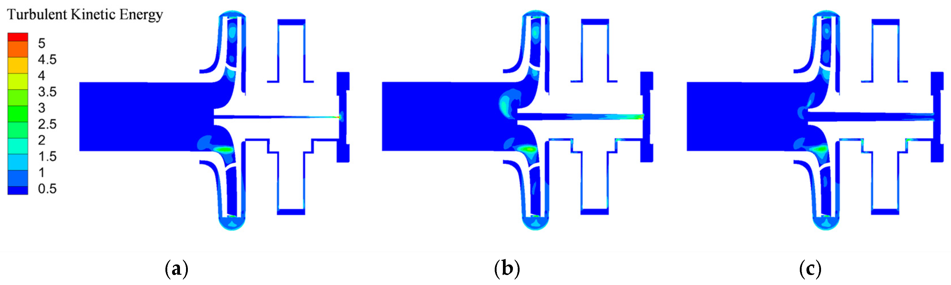
As for the diverging balance holes, as shown in Figure 22, the hole diameter increases gradually along the axial direction, allowing the fluid to undergo a continuous and smooth diffusion process within the hole. This effectively suppresses local acceleration and flow separation. Such a structure not only weakens the concentration of the jet at the balance hole outlet but also enables the backflow to enter the impeller inlet region in a more uniform and lower-momentum manner, thereby significantly reducing the disturbance to the main flow. Accordingly, the turbulent kinetic energy level near the impeller inlet is markedly lower than that observed with the constant-diameter balance hole, indicating a more stable flow pattern. Therefore, the diffuser-type balance hole can effectively reduce axial force while simultaneously mitigating the turbulence dissipation induced by backflow interference, which is beneficial for minimizing efficiency loss.
The performance of centrifugal pumps is mainly assessed by the characteristic parameters of head, efficiency and shaft power. The introduction of the balance hole will lead to liquid leakage and the return of fluid from the motor air gap to the impeller, thus interfering with the flow state of the impeller inlet, increasing the flow loss, which in turn reduces the efficiency and head of the pump.
The head H of a centrifugal pump is defined as the mechanical energy acquired per unit weight of fluid. Its calculation formula is derived from the total pressure difference between the outlet and inlet:
H = p out p in ρ g
where Pout, Pin is the total pressure difference between inlet and outlet (Pa), and g is the gravitational acceleration (m s−2).
The shaft power is given by:
P = M ω
ω = 2 π n 60
where M is the resultant moment about the impeller axis, which combines the contributions from the pressure side, suction side, front shroud, and rear shroud surfaces of the blades (N m), and ω is the impeller angular velocity (rad s−1).
The centrifugal-pump efficiency is expressed as:
η =   ρ g Q H 1000 P × 100 %
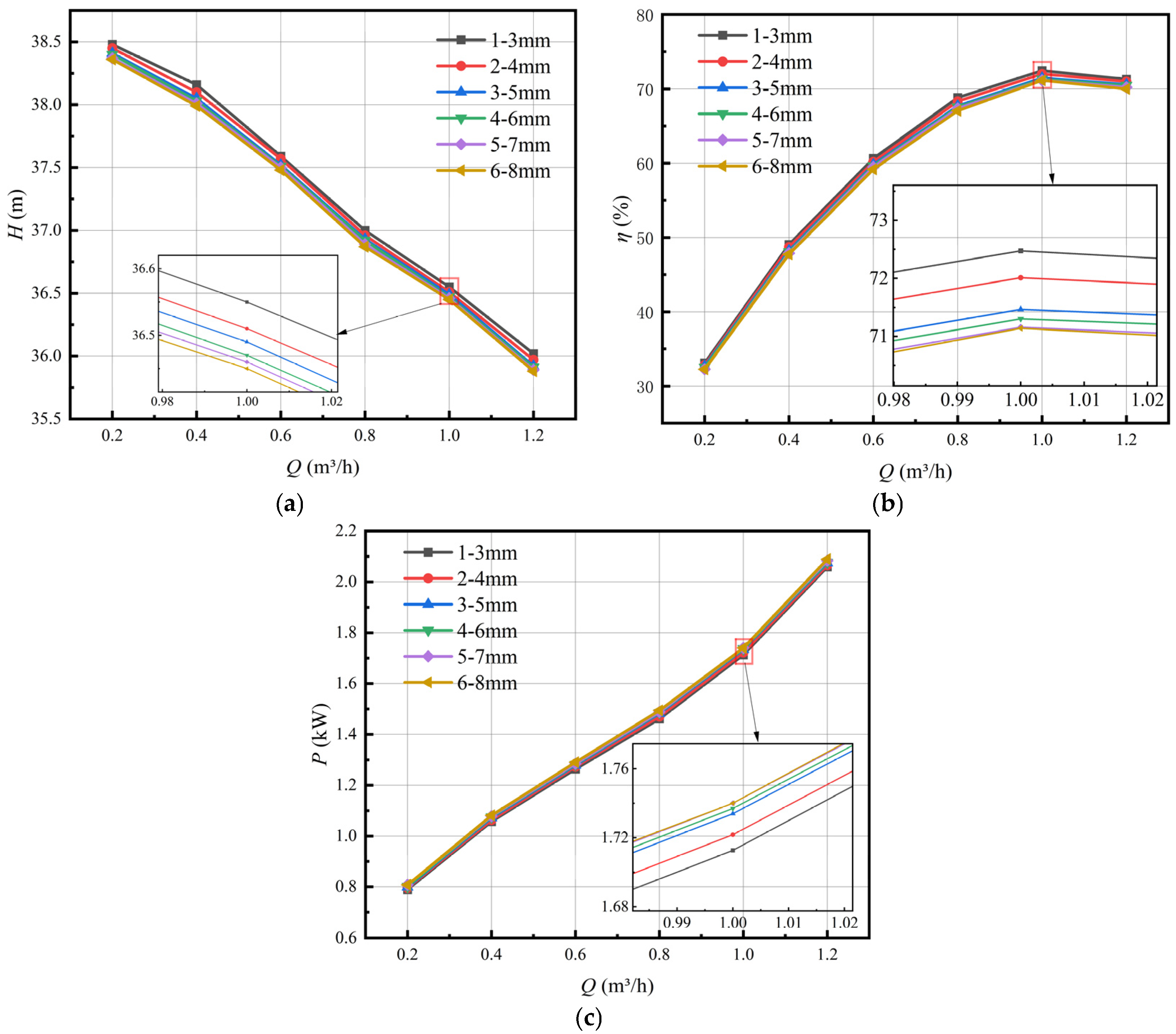
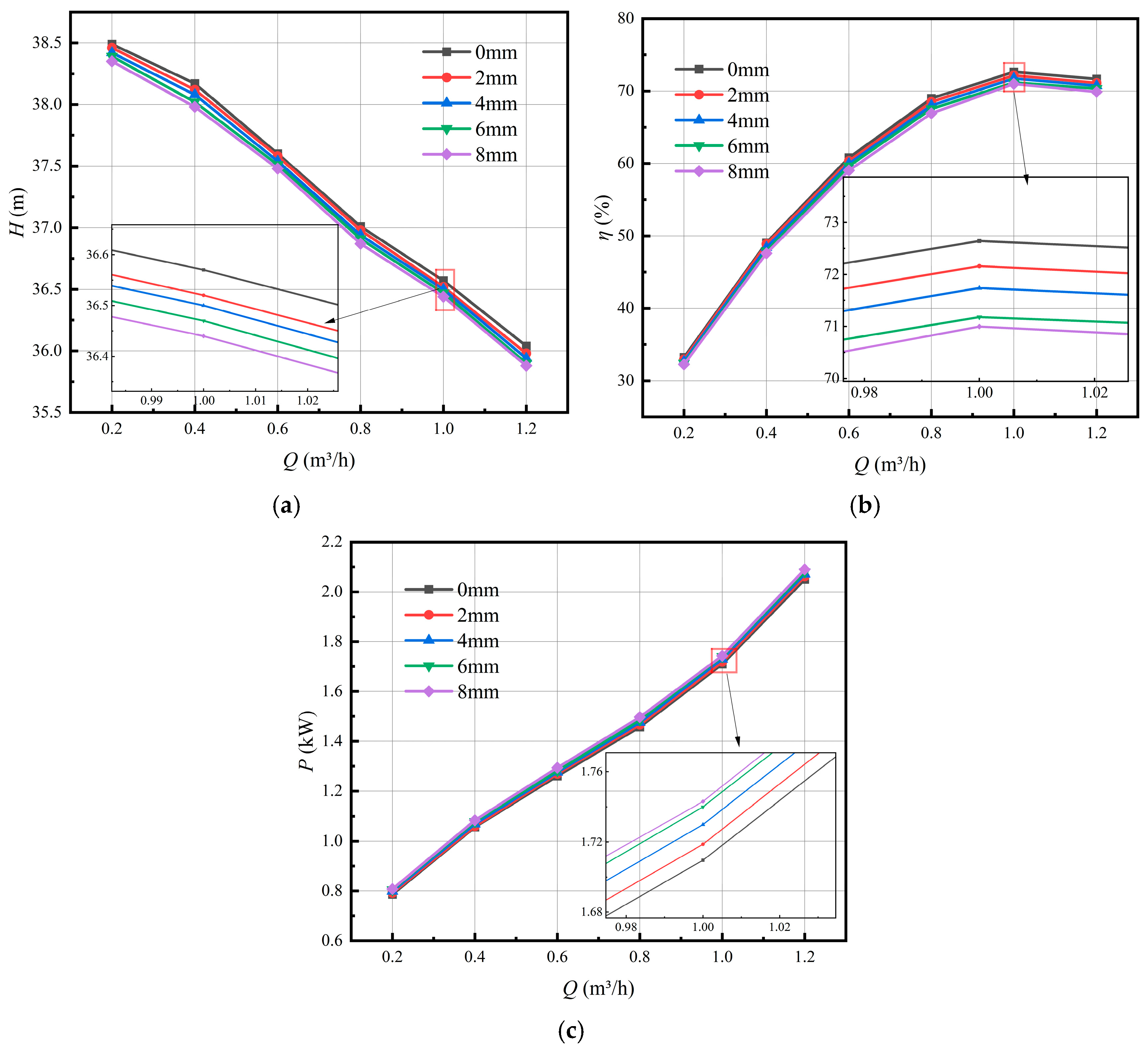
As can be seen from Figure 23, Figure 24 and Figure 25, electromagnetic direct-drive centrifugal-pump head and efficiency, with the increase in the diameter and length of the balance holes, gradually decreases, while there is a corresponding increase in shaft power. Compared to the model with no balance hole, in the model with an opening length of 100 mm 8 mm balance hole, the head decreased 0.36–0.50%, and efficiency decreased 0.99–2.07%. With a length of 100 mm and a balance hole diameter of 4 mm, compared with the opening length 84 mm and a 4 mm diameter balance hole, the head decreased 0.16–0.22%, and efficiency decreased in 0.49–0.72%. The comparison between the diverging balance hole model with 100 mm length and 1–3 mm diameter variation and the diverging balance hole model with 100 mm length and 6–8 mm diameter variation shows a head reduction of 0.31–0.44% and an efficiency decrease of 0.85–1.78%.
But overall, despite the addition of balance holes which led to centrifugal-pump head and efficiency decreases, the head drop did not exceed 0.5% and the efficiency drop was not more than 3%, which is significantly smaller, balancing the length parameters of the pump efficiency relative to the impact of the diameter parameters. Existing studies on axial-force control in centrifugal pumps, together with pump design guidelines, indicate that balance holes, as a commonly employed as an axial-force balancing measure, typically result in an efficiency reduction of approximately 2–5%, which is regarded as acceptable in engineering practice [35,36]. In this context, the present results demonstrate that the introduction of balance holes has only a minor influence on the overall pump performance. Based on the comprehensive consideration of axial-force reduction effect and hydraulic performance changes, the adoption of a diverging balance hole structure with a diameter range of 4–6 mm can significantly reduce axial force while keeping head and efficiency losses within an acceptable engineering range. Therefore, a small sacrifice in head and efficiency to achieve effective axial-force balancing represents a reasonable and practical design choice.

5. Conclusions

In this study, the axial-force balance problem presented by disc-type electromagnetic direct-drive centrifugal pumps has been analysed in depth by numerical simulation methods, focusing on the effects of variations in the diameter and length of the balance holes and their aperture steps on the performance of the pump and the axial force. The research results are summarised as follows:
(1) The structural parameters of the balance holes have a significant effect on the motor air-gap pressure distribution. As the diameter of the multi-diameter balance holes increases from 0 mm to 8 mm, the motor air-gap pressure decreases significantly, from 216.175 kPa to 91.02 kPa, a reduction of 57.9%. When the diameter of the balance holes remains constant, increasing the length from 84 mm to 100 mm only results in a slight decrease in air-gap pressure, from 140.85 kPa to 139.65 kPa, less than 1%, indicating that the change in length has a more limited effect on the motor air-gap pressure. As for the diverging balance holes with gradually varying diameters along the axial direction, the pressure change falls between the extremes of the corresponding constant-diameter balance holes at both ends.
(2) There are significant differences in the axial-force reduction effects of different balance hole structures. The multi-diameter balance holes (diameter 0–8 mm) can reduce the axial force from 703.45 N to 125.57 N, a reduction of 82.1%, while the constant-diameter, variable-length balance holes (length 84–100 mm) only cause a 4.3% change in axial force. The diverging balance holes achieve smooth axial-force reduction while maintaining more stable pressure distribution, with the reduction magnitude varying between the corresponding minimum and maximum hole diameters.
(3) The axial forces at the shaft end and the front/rear pump chambers account for the major portion of the total axial force. After adding balance holes, the axial forces at the shaft end and in the pump chambers are significantly reduced, leading to a substantial decrease in total axial force. Therefore, when optimizing the balance hole design, focus should be placed on the axial-force distribution in these regions and their contribution to the total axial force.
(4) The influence of balance hole parameters on pump hydraulic performance is relatively minor. Turbulent kinetic energy analysis demonstrates that the diverging balance holes effectively suppress flow disturbances and turbulent intensity in the impeller inlet region, thereby contributing to a more stable flow structure and higher hydraulic efficiency, while reducing axial force. Based on these findings, a diverging balance hole structure with a diameter range of 4–6 mm is selected as the optimal design scheme for the disk-type electromagnetic direct-drive centrifugal pump. This choice balances axial-force reduction effectiveness with minimal impacts on head and efficiency, representing a practical compromise between performance and structural feasibility.
(5) The diverging balance hole demonstrates its advantages by reducing axial force while maintaining satisfactory pump hydraulic performance. The present study focused on a specific pump configuration and operating point. Future work should verify these performance determinations under broadly varying conditions (e.g., varying speeds, fluids, and pump scales) to further evaluate their robustness and universality.

Author Contributions

Conceptualization, methodology, supervision, R.W.; investigation, formal analysis, writing—original draft, B.L.; funding acquisition, writing—review and editing, X.L.; investigation, data curation, F.W.; software, validation, B.W. All authors have read and agreed to the published version of the manuscript.

Funding

This research received no external funding.

Data Availability Statement

The data used to support the findings of this study are available from the corresponding author upon request.

Conflicts of Interest

The authors report there are no competing interests to declare.

Nomenclature

QFlow rate (m3h−1)
nRotational speed (rpm)
HGravity acceleration (m)
ZNumber of blades (-)
DImpeller diameter (mm)
BImpeller outlet width (mm)
D1Impeller inlet diameter (mm)
nsSpecific speed (-)
729PPower (kW)
ρDensity of the mixture (kg m−3)
uVelocity (m s−1)
pPressure (pa)
tTime (m)
xSpatial coordinates (m)
μDynamic viscosity (pa s)
SSource term (-)
GkGeneration term of turbulent kinetic energy k due to mean velocity gradients (-)
CEmpirical constants (-)
σkTurbulent Prandtl numbers for k (-)
σεTurbulent Prandtl numbers for ε (-)
μtTurbulent viscosity (pa s)
CμEmpirical constant (pa s)
PoutOutlet Total Pressure (pa)
PinInlet Total Pressure (pa)
gGravitational acceleration (m s−2)
MThe resultant moment about the impeller axis, which combines the contributions from the pressure side, suction side, front shroud, and rear shroud surfaces of the blades (N m)
ωThe impeller angular velocity (rad s−1)
ηPump efficiency (-)

References

  1. Jiang, H.; Dong, W.; Li, S.; He, F. Optimization of centrifugal pump performance and excitation force based on machine learning and enhanced non-dominated sorting genetic algorithm III. Eng. Appl. Artif. Intell. 2025, 143, 110036. [Google Scholar] [CrossRef] [Scilit]
  2. Fathi, M.; Alemi, H.; Raisee, M.; Nourbakhsh, A. Numerical investigation of axial force of a centrifugal pump in the reverse mode. J. Phys. Conf. Ser. 2024, 2707, 012047. [Google Scholar] [CrossRef] [Scilit]
  3. Dong, J.; Liang, W.; Dong, W. Numerical calculation and analysis of axial force of multistage centrifugal submersible pump. J. Phys. Conf. Ser. 2022, 2217, 012046. [Google Scholar] [CrossRef] [Scilit]
  4. Yan, S.; Kan, Y.; Li, X.; Xiao, L.; Ye, Z. Numerical Calculation and Experimental Study of the Axial Force of Aero Fuel Centrifugal Pumps. Appl. Sci. 2024, 14, 4313. [Google Scholar] [CrossRef] [Scilit]
  5. Jiang, H.; Dong, W.; Li, P.; Zhang, H. Based on Wavelet and Windowed Multi-Resolution Dynamic Mode Decomposition, Transient Axial Force Analysis of a Centrifugal Pump under Variable Operating Conditions. Energies 2023, 16, 7176. [Google Scholar] [CrossRef] [Scilit]
  6. Chen, Q.; Huan, Y.; Peng, Q.; Xin, Y.; Hui, N. Flow mechanism and axial force distribution characteristics of multistage pump cavity. Sci. Prog. 2022, 105, 368504221145575. [Google Scholar] [CrossRef] [Scilit]
  7. Zhou, L.; Shi, W.; Li, W.; Agarwal, R. Numerical and Experimental Study of Axial Force and Hydraulic Performance in a Deep-Well Centrifugal Pump With Different Impeller Rear Shroud Radius. J. Fluids Eng. 2013, 135, 104501. [Google Scholar] [CrossRef] [Scilit]
  8. Cheng, G.; Wei, Y.; Sun, F.; Wu, X.; Fang, S. Investigation of the Impact of Wear-Ring Clearance on Hydraulic Performance and Axial Thrust in Multistage Low-Specific-Speed Centrifugal Pumps. J. Fluids Eng. 2025, 147, 101208. [Google Scholar] [CrossRef] [Scilit]
  9. Liu, Z.; Xu, L.; Jia, X.; Wu, J.; Wang, D. Analysis of liquid flow and axial force calculation in axial clearance for floating impeller of centrifugal pump. Nongye Gongcheng Xuebao/Trans. Chin. Soc. Agric. Eng. 2013, 29, 79–85. [Google Scholar] [CrossRef]
  10. Gu, Y.; Sun, H.; Wang, C.; Lu, R.; Liu, B.; Ge, J. Effect of Trimmed Rear Shroud on Performance and Axial Thrust of Multi-Stage Centrifugal Pump With Emphasis on Visualizing Flow Losses. J. Fluids Eng. 2023, 146, 011204. [Google Scholar] [CrossRef] [Scilit]
  11. Wu, Y.; Ge, P.; Bi, W. Analysis of axial force of double circular arc helical gear hydraulic pump and design of its balancing device. J. Cent. South Univ. 2021, 28, 418–428. [Google Scholar] [CrossRef] [Scilit]
  12. Babayigit, O.; Ozgoren, M.; Aksoy, M.H.; Kocaaslan, O. The Effect of Balance Holes to Centrifugal Pump Performance. In Proceedings of the International Conference on Numerical Analysis and Applied Mathematics 2016 (ICNAAM-2016), Rhodes, Greece, 19–25 September 2016; Volume 1863. [Google Scholar] [CrossRef] [Scilit]
  13. Cao, W.; Dai, X.; Hu, Q. Effect of impeller reflux balance holes on pressure and axial force of centrifugal pump. J. Cent. South Univ. 2015, 22, 1695–1706. [Google Scholar] [CrossRef] [Scilit]
  14. Fathi, M.; Raisee, M.; Nourbakhsh, S.A.; Arani, H.A. The effect of balancing holes on performance of a centrifugal pump: Numerical and experimental investigations. IOP Conf. Ser. Earth Environ. Sci. 2019, 240, 032017. [Google Scholar] [CrossRef] [Scilit]
  15. Zhao, J.; Mu, J.; Zheng, S.; Lu, H.; Wang, H. The Impact of Balance Hole Radial Position of Centrifugal Pump on Axial Force and External Characteristics. Appl. Mech. Mater. 2012, 130–134, 1691–1695. [Google Scholar] [CrossRef] [Scilit]
  16. Xun, D.; Qiu, N.; Wei, Y.; Zhu, H.; Zhou, W.; Xu, P.; Zhang, W. Effect of the Circumferential Position of Balance Holes on the Cavitation Performance and Cavitation Erosion of Centrifugal Pump. J. Appl. Fluid Mech. 2024, 18, 131–144. [Google Scholar] [CrossRef] [Scilit]
  17. Cheng, X.; Luo, J.; Xiong, B.; Jiang, Y. Influence of the Balance Hole Circumferential Position on the Cavitation Performance of the Semiopen Impeller Centrifugal Pump. Math. Probl. Eng. 2021, 2021, 4472433. [Google Scholar] [CrossRef] [Scilit]
  18. Dong, W.; Chu, W.; Liu, Z. Influences of the diameter of the balance hole on the flow characteristics in the hub cavity of the centrifugal pump. J. Hydrodyn. 2019, 31, 1060–1068. [Google Scholar] [CrossRef] [Scilit]
  19. Zhang, S.; Li, H.; Xi, D. Investigation of the Integrated Model of Side Chamber, Wear-Rings Clearance, and Balancing Holes for Centrifugal Pumps. J. Fluids Eng. 2019, 141, 101101. [Google Scholar] [CrossRef] [Scilit]
  20. Luo, X.; Xie, H.; Feng, J.; Ge, Z.; Zhu, G. Influence of the balance hole on the performance of a gas–liquid two–phase centrifugal pump. Ocean. Eng. 2022, 244, 110316. [Google Scholar] [CrossRef] [Scilit]
  21. Jin, F.; Li, N.; Tao, R.; Xiao, R. Investigation of the self-balance impeller of a canned motor pump for axial force reduction. Proc. Inst. Mech. Eng. Part C J. Mech. Eng. Sci. 2023, 237, 1806–1817. [Google Scholar] [CrossRef] [Scilit]
  22. Chen, Q.; Yang, L.; Qi, Z.; Yang, C. Analysis of the axial force distribution characteristics of multistage pumps and its correlation with hydraulic property. Adv. Mech. Eng. 2022, 14, 168781322211305. [Google Scholar] [CrossRef] [Scilit]
  23. Li, Z.; Dong, W.; Jiang, H.Q. Multi-objective optimization of centrifugal pumps based on extreme learning machine with Adaptive Non-dominated Sorting Genetic Algorithms III. Phys. Fluids 2025, 37, 037191. [Google Scholar] [CrossRef] [Scilit]
  24. Kim, W.; Yun, J. CFD Analysis on the Balancing Hole Design for Magnetic Drive Centrifugal Pumps. Energies 2020, 13, 5865. [Google Scholar] [CrossRef] [Scilit]
  25. Cheng, K.; Jiang, T.; He, Y.J.; Wang, X.L. Volute clapboard and clearance of wear-ring effect on the operation characteristics of canned motor pump. Front. Energy Res. 2023, 11, 1170123. [Google Scholar] [CrossRef] [Scilit]
  26. Conaway, E.; Matos, J.; Mesiano, R.; Asme. The Effects of Multiphase, Multi-Viscosity Fluids on Axial Thrust and Cooling Flow Performance of a Canned Motor Pump. In Proceedings of the ASME-JSME-KSME Joint Fluids Engineering Conference (AJK-FED 2019), San Francisco, CA, USA, 28 July–1 August 2019. [Google Scholar]
  27. Han, S.; Duan, Y.; Wan, Y.; Ge, J.; Li, G. Numerical simulation for influence of rear wear ring and balance hole on performance of the canned motor pump. Can. J. Chem. Eng. 2025, 104, 1578–1598. [Google Scholar] [CrossRef] [Scilit]
  28. Xia, B.; Kong, F.; Bai, Y.; Duan, X. Numerical Simulation and Performance Prediction of Multistage Canned Motor Pump. In Proceedings of the Asme Fluids Engineering Division Summer Meeting, Washington, DC, USA, 10–14 July 2016; Volume 1A. [Google Scholar]
  29. Zhu, Q.; Gu, Y.; Bian, J. Impact of the Magnetic Gap in Submerged Axial Flux Motors on Centrifugal Pump Hydraulic Performance and Internal Flow. Machines 2025, 13, 721. [Google Scholar] [CrossRef] [Scilit]
  30. Liang, X.; Zhang, Z.; Zhao, C.; Zheng, J.; Zhang, R.; Xiang, Y. A novel integrated motor-driven centrifugal pump and its hydrodynamic performance improvement. In Proceedings of the 2023 7th International Conference on Transportation Information and Safety (ICTIS), Xi’an, China, 4–6 August 2023; pp. 636–643. [Google Scholar]
  31. Adanta, D.; Muhammad, N.; Fattah, I.M.R. Comparison of Standard k-ε and SST k-ωturbulence Model for Breastshot Waterwheel Simulation. J. Mech. Sci. Eng. 2020, 7, 039–044. [Google Scholar] [CrossRef] [Scilit]
  32. Liang, X.; Wang, B.; Shen, H.; Qiao, Y.; Wang, R.; Wang, F.; Li, B. A novel self-priming centrifugal pump and the influence of cooling channels on its hydrodynamic performance. Flow Meas. Instrum. 2026, 108, 103205. [Google Scholar] [CrossRef] [Scilit]
  33. Sun, J.; Lu, J.; Zhang, W.; Xu, E.; Zhao, R. Investigation on the rotor suspension characteristics under passive control of magnetically levitated centrifugal pump from the pump–motor coupling perspective. J. Comput. Des. Eng. 2025, 12, 42–54. [Google Scholar] [CrossRef] [Scilit]
  34. Dong, W.; Liu, Z.; Zhang, H.; Zhang, G.; Jiang, H.; Li, P. Effects of the Balance Hole Diameter on the Flow Characteristics of the Rear Chamber and the Disk Friction Loss in the Centrifugal Pump. Processes 2022, 10, 613. [Google Scholar] [CrossRef] [Scilit]
  35. Pehlivan, H.; Parlak, Z. Investigation of Parameters Affecting Axial Load in an End Suction Centrifugal Pump by Numerical Analysis. J. Appl. Fluid Mech. 2019, 12, 1615–1627. [Google Scholar] [CrossRef] [Scilit]
  36. Sefaci, S.; Babayigit, O.; Koçak, S. Design Optimization Of Balancing Hole In A Centrifugal Pump Impeller By Using Experimental Design Methods. Bitlis Eren Üniversitesi Fen Bilim. Derg. 2022, 11, 436–448. [Google Scholar] [CrossRef] [Scilit]
Figure 1. Three-dimensional structure of disc electromagnetic direct-drive centrifugal pumps.
Processes 14 00813 g001
Figure 2. Schematic diagram of circulation flow path.
Processes 14 00813 g002
Figure 3. Schematic diagram of a water body model of disc-type electromagnetic direct-drive centrifugal pump. 1—Inlet extension, 2—Front pump chamber, 3—Impeller, 4—Volute, 5—Outlet extension, 6—Rear pump chamber, 7—Balance hole, 8—Motor air gap.
Processes 14 00813 g003
Figure 4. Diverging balance hole structures.
Processes 14 00813 g004
Figure 5. Mesh division of the electromagnetic direct-drive centrifugal pump.
Processes 14 00813 g005
Figure 6. Meshing details of the impeller, volute, motor air gap and balance hole.
Processes 14 00813 g006
Figure 7. Mesh irrelevance check: (a) head and efficiency, (b) total axial force and motor air-gap pressure.
Processes 14 00813 g007
Figure 8. Boundary conditions.
Processes 14 00813 g008
Figure 9. Pressure distribution in the air gap of a direct-drive centrifugal-pump motor with multi-diameter balance holes: (a) without balance holes, (b) balance hole diameter 4 mm, (c) balance hole diameter 8 mm.
Processes 14 00813 g009
Figure 10. Pressure distribution in the air gap of a direct-drive centrifugal-pump motor with constant-diameter, variable-length balance holes: (a) balance hole length 84 mm, (b) balance hole length 92 mm, (c) balance hole length 100 mm.
Processes 14 00813 g010
Figure 11. Pressure distribution in the air gap of an electromagnetic direct-drive centrifugal pump with diverging balance holes: (a) balance hole diameter 1–3 mm, (b) balance hole diameter 4–6 mm, (c) balance hole diameter 6–8 mm.
Processes 14 00813 g011
Figure 12. Pressure distribution on the shaft end face of a disc-type electromagnetic direct-drive centrifugal pump with multi-diameter balance holes: (a) without balance hole, (b) balance hole diameter 4 mm, (c) balance hole diameter 8 mm.
Processes 14 00813 g012
Figure 13. Pressure distribution on the shaft end face of a disc-type electromagnetic direct-drive centrifugal pump with constant-diameter variable-length balance holes: (a) balance hole length 100 mm, (b) balance hole length 92 mm, (c) balance hole length 84 mm.
Processes 14 00813 g013
Figure 14. Pressure distribution on the shaft end face of a disc-type electromagnetic direct-drive centrifugal pump with diverging balance holes: (a) balance hole diameter 1–3 mm, (b) balance hole diameter 4–6 mm, (c) balance hole diameter 6–8 mm.
Processes 14 00813 g014
Figure 15. Radial variation of axial centre pressure at the shaft end of a disc-type direct-drive centrifugal pump with different balance hole configurations: (a) multi-diameter balance holes; (b) constant-diameter, variable-length balance holes; (c) diverging balance holes.
Processes 14 00813 g015
Figure 16. Schematic diagram of axial force.
Processes 14 00813 g016
Figure 17. Effects of balance hole diameter variation on axial force and leakage flow. (a) Axial-force components and total axial-force curves for multi-diameter balance holes. (b) Leakage flow rates of multi-diameter balance holes.
Processes 14 00813 g017
Figure 18. Effects of balance hole length variation on axial force and leakage flow. (a) Axial-force components and total axial-force curves for constant-diameter, variable-length balance holes. (b) Leakage flow rates of constant-diameter, variable-length balance holes.
Processes 14 00813 g018
Figure 19. Effects of diameter variation in diverging balance holes on axial force and leakage flow. (a) Axial-force components and total axial-force curves for diverging balance holes. (b) Leakage flow rates of diverging balance holes.
Processes 14 00813 g019
Figure 20. Variation of turbulent kinetic energy in an electromagnetic direct-drive centrifugal pump with multi-diameter balance holes: (a) without balance holes, (b) balance hole diameter 4 mm, (c) balance hole diameter 8 mm.
Processes 14 00813 g020
Figure 21. Turbulent kinetic energy variation in a direct-drive centrifugal pump with constant-diameter, variable-length balance holes: (a) balance hole length 100 mm, (b) balance hole length 92 mm, (c) balance hole length 84 mm.
Processes 14 00813 g021
Figure 22. Turbulent kinetic energy variation in an electromagnetic direct-drive centrifugal pump with diverging balance holes: (a) balance hole diameter 1–3 mm, (b) balance hole diameter 4–6 mm, (c) balance hole diameter 6–8 mm.
Processes 14 00813 g022
Figure 23. Performance curves for an electromagnetic direct-drive centrifugal pump with multi-diameter balance holes: (a) flow—head curve, (b) flow—efficiency curve, (c) flow—axial power curve.
Processes 14 00813 g023
Figure 24. Performance curves for an electromagnetic direct-drive centrifugal pump with constant-diameter, variable-length balance holes: (a) flow—head curve, (b) flow—efficiency curve, (c) flow—axial power curve.
Processes 14 00813 g024
Figure 25. Performance curves for an electromagnetic direct-drive centrifugal pump with diverging balance holes: (a) flow—head curve, (b) flow—efficiency curve, (c) flow—axial power curve.
Processes 14 00813 g025
Table 1. IS50-32-160 single-stage single-suction electromagnetic direct-drive centrifugal pump, basic parameters.
Parameter NameQ (m3h−1)n (rpm)H (m)ZD (mm)B (mm)D1 (mm)nsP (kW)
Numerical value12.52900326160565632.62.2
Table 2. Twenty-four kinds of balance hole structure.
Multi-Diameter Balance Holes (mm)Length Variation of Equal-Diameter Variable-Length Balance Holes
(mm)
Gradient Variation of Diameter in Diverging Balance Holes
(mm)
0841–3
1862–4
2883–5
3904–6
4925–7
5946–8
696
798
8100
Table 3. Number of grids for each computational domain.
Computational Domain NameNumber of Meshes/10,000Mesh Type
Inlet Extension27.6Structural
Outlet Extension32.1Structural
Front Pump Chamber41.2Unstructured
Rear Pump Chamber35.7Unstructured
Impeller100.1Structural
Volute82.4Unstructured
Motor Air Gap65.2Unstructured
Balance Hole15.4Structural
Table 4. Boundary conditions.
Boundary NameBoundary ConditionCondition Setting
ImpellerRotating walln = 2900 rpm
VoluteStationary wallStationary
Face of front pump chamber near impellerRotating walln = 2900 rpm
Front pump chamberStationary wallStationary
Rear pump chamber near impellerRotating walln = 2900 rpm
Rear pump chamberStationary wallStationary
Shaft end faceRotating walln = 2900 rpm
Motor air gap rotor faceRotating walln = 2900 rpm
Motor air gap remaining surfaceStationary wallStationary
Outlet extensionStationary wallStationary
Inlet extensionStationary wallStationary
Equilibrium holeRotating walln = 2900 rpm
Inlet boundaryPressure inletRelative pressure 0
Outlet boundaryMass flow outlet3.465 kg/s
Disclaimer/Publisher’s Note: The statements, opinions and data contained in all publications are solely those of the individual author(s) and contributor(s) and not of MDPI and/or the editor(s). MDPI and/or the editor(s) disclaim responsibility for any injury to people or property resulting from any ideas, methods, instructions or products referred to in the content.