Article

Interaction Between Advance Passive Support Force and Bolt–Cable Systems in Deep Roadways

1
Shandong University of Science and Technology, Qingdao 266590, China
2
Yankuang Energy Group Company Limited, Jining 272001, China
*
Author to whom correspondence should be addressed.
Processes 2026, 14(5), 770; https://doi.org/10.3390/pr14050770
Submission received: 31 January 2026 / Revised: 15 February 2026 / Accepted: 24 February 2026 / Published: 27 February 2026
(This article belongs to the Section Petroleum and Low-Carbon Energy Process Engineering)

Abstract

Advance hydraulic supports are widely applied in deep coal mine roadways; however, inappropriate initial support force often leads to either insufficient roof control or over-support, weakening the effectiveness of bolt–cable systems. To clarify the interaction mechanism between advance passive support and active bolt–cable reinforcement, an advance roadway support model was developed using FLAC3D based on the geological conditions of the 1432 working face in the Dongtan Coal Mine. Numerical simulations were conducted by varying the initial support force from 0 to 14 MPa, and the corresponding roof displacement, bolt stress, and cable axial force responses were systematically analyzed. The results indicate that roof subsidence decreases nonlinearly with increasing support force, exhibiting a rapid suppression stage (0–10 MPa) and a stable coordination stage (10–12 MPa). Within this optimal range, load transfer from the roof to the passive support is significantly enhanced, leading to effective stress relief and homogenization in the bolt–cable system. When the support force exceeds 12 MPa, further deformation control becomes marginal, indicating a transition from cooperative load sharing to over-support. These findings reveal the staged interaction mechanism between advance passive support and active reinforcement systems, providing a quantitative basis for selecting appropriate initial support force in deep roadway engineering.

1. Introduction

With the continuous development of China’s coal resources, the environment of mining and excavation roadways has become increasingly complex. The application of advance hydraulic supports in roadway advance support has grown significantly [1,2,3,4]. Passive support provided by advance hydraulic supports has gradually become a crucial technical measure for ensuring roadway safety. Investigating the stress characteristics of rock bolts and cables under passive support from advance supports, along with their synergistic support mechanisms, holds significant importance for enhancing the effectiveness of surrounding rock support in deep roadways [5,6,7,8,9,10].
With the expansion of mining space and the increase in cross-sectional dimensions, a single support method can hardly meet the stability requirements of roadway roofs. Especially under the action of complex dynamic pressure, surrounding rocks still suffer from persistent deformation, coal pillar stress concentration, and frequent roof weighting. To address these challenges, the coupled application of multiple support methods is more conducive to coping with the complex conditions of roadways.
Aiming at the broken, loose roof of coal seams, a collaborative control technology scheme combining high preload bolt–cable and shotcreting support was proposed [11], which basically solved the roadway support problem of broken, loose roofs in coal mines. Relevant research [12] also established a theoretical model of coupled support between composite arch and surrounding rock preload reinforcement. The results showed that bolt length and spacing affect support strength by changing the thickness of the composite arch, showing a positive and negative correlation with support strength, respectively, and the influence is significant; roadway span affects support strength by changing the height–span ratio of the composite arch, showing a negative correlation with support strength, while preload affects support strength by enhancing surrounding rocks, showing a positive correlation with support strength. In addition, an independently developed dynamic–static coupled mechanical property test system for bolts [13] revealed the mechanical response and energy evolution law of bolts under different prestresses, clarified the impact resistance change characteristics under dynamic–static coupling, and solved the problem of lack of dynamic basis for bolt prestress design in deep surrounding rock support.
In terms of the coordination between advance hydraulic supports and active support, comparative analysis [14] has been conducted on the damage characteristics of roadways under different support schemes of single props and supplementary cables. After the application of cable reinforcement support in the advance section of mining roadways, the deformation of surrounding rock was effectively controlled. Relevant studies [15] established a mechanical model of surrounding rock supported by advance hydraulic support group-anchoring coupling and revealed the superiority of the “continuous gradual change” unequal strength support strategy in significantly reducing roof deformation and stress. Based on the numerical simulation and comparative analysis of hydraulic supports, bolts, and their combined support methods, it has been confirmed [16] that the combined bolt support method can effectively weaken the roof stress superposition effect and control surrounding rock deformation during the residual coal recovery through goafs, which is regarded as the optimal support scheme.
The aforementioned research provides a theoretical foundation for advance support in roadways. Many mines have begun employing coordinated action between active support systems (cable anchors and rock bolts) and advance hydraulic supports to further ensure roadway safety. In practical application, the limited adaptability of advance hydraulic supports can adversely affect both the roadway roof and the anchor rod/cable support system [17]. Over-support and under-support phenomena frequently occur with advance hydraulic supports in roadways [18]. Against this backdrop, the interaction mechanism between advance hydraulic supports—a typical passive support method—and active support systems comprising bolts and cables warrants in-depth investigation. Therefore, using the Dongtan Coal Mine of Yankuang Energy Group Co., Ltd. as a case study, an advance roadway support model was established using FLAC3D 7.0 software. Analyses of stresses and displacements in the anchor bolts, cables, and roadway roof were conducted for different advance support intensities, revealing their distribution patterns. This identified the optimal advance support intensity, providing valuable insights for subsequent studies on active–passive coupled support systems.

2. Materials and Methods

2.1. Engineering Background and Geological Conditions

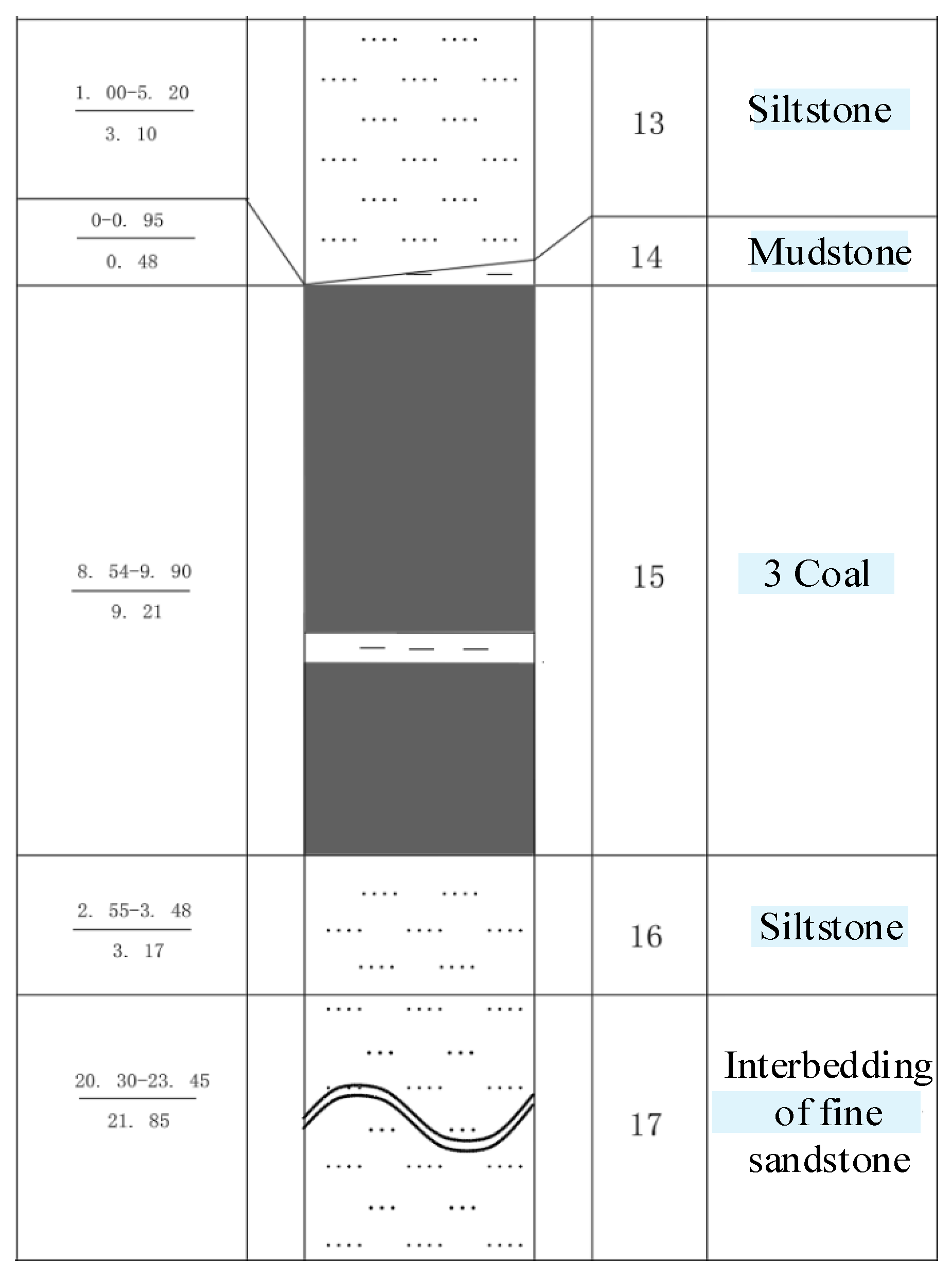
The 14320II fully mechanized longwall face at Dongtan Coal Mine, Yankuang Energy Group, is located in the northwest section of the 14th mining area, west of the upper track road in the 14th mining area. It extends from the western cut-off point northeast to the designed stop line. The two parallel roadways serve as transport and railways, respectively: the northern roadway functions as the transport roadway (1596 m long), while the southern roadway serves as the railway (1604 m long). The longwall has an inclination length of 363.8 m and a total area of 583,354 m2. The integrated pillar configuration is shown in Figure 1.
The mined coal seam is Coal Seam 3, exhibiting relatively consistent overall thickness. It generally thickens toward the northwest and thins toward the southeast. The seam is stable with complex structure, containing 1–2 layers of gangue intercalations. One layer is located 3.25–3.48 m above the Coal Seam 3 floor (a 0–0.20 m thick mudstone or siltstone gangue intercalation, developed in the eastern part of the working face), and another layer is located 3.20–3.80 m below the roof of Coal Seam 3 (a 0.02–0.03 m thick siltstone intercalation, serving as a key marker layer for Coal Seam 3). The coal seam dip angle ranges from 0 to 6°, averaging 3°, with a Mohs hardness of f = 2 to 3. The advance roadway employs combined support using trapezoidal cross-section mesh belts and rock bolts. The working face is equipped with 211 hydraulic supports, including 8 end supports (4 at the haulage end and 4 at the roadhead end) and 203 intermediate supports. The haulage end is equipped with 4 ZFG12000/22/38 supports, while the haulage end features 3 ZFG12000/26/42 supports (Yankuang Donghua Heavy Industry Co., Ltd., Jining, China) and 1 ZFG12000/22/38 support (Zhengzhou Coal Machinery Comprehensive Machinery Equipment Co., Ltd., Jining, China).

2.2. Boundary Conditions and Parameter Settings

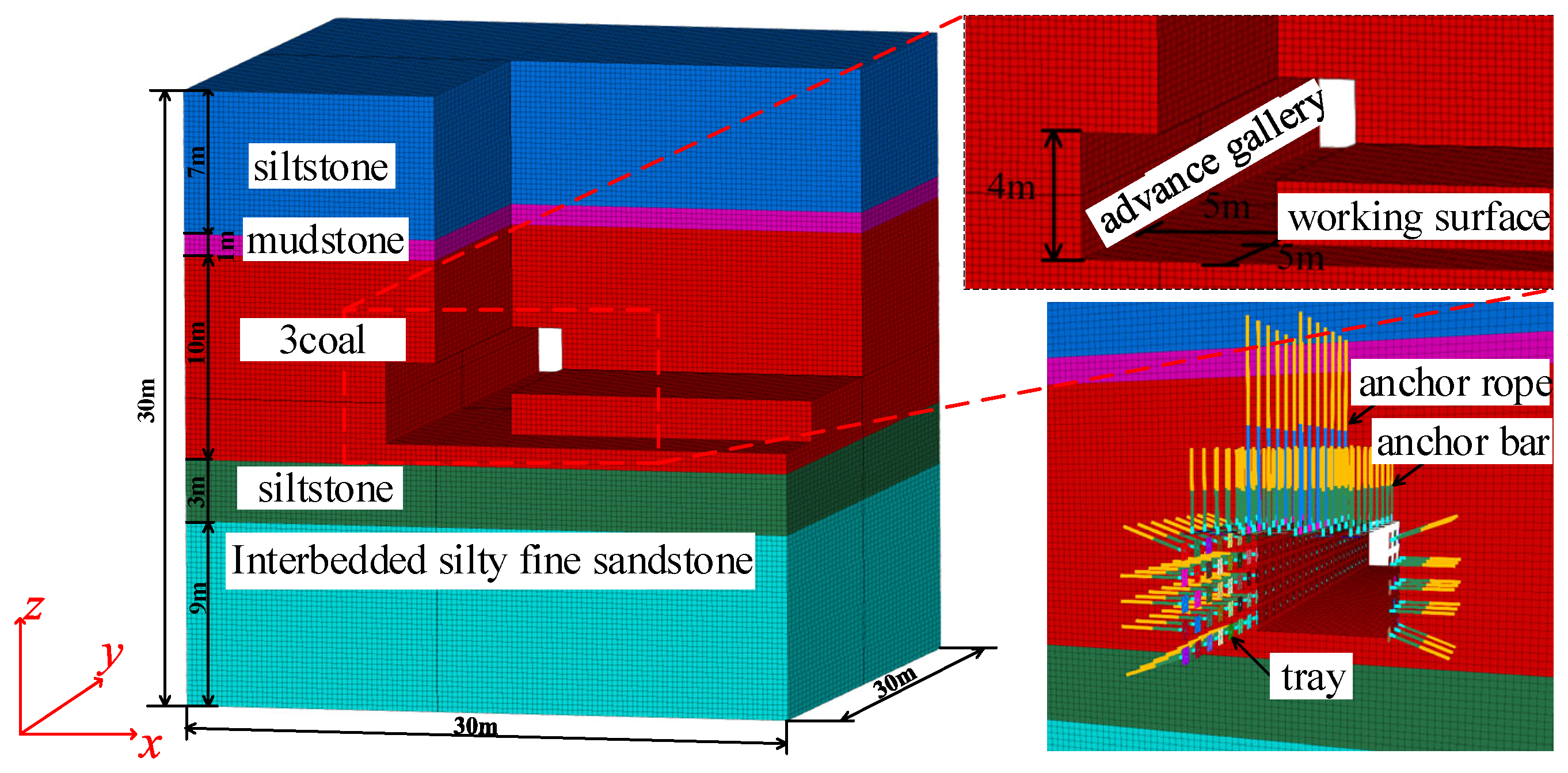
Based on the comprehensive columnar diagram of the 14320 II fully mechanized longwall face, a numerical calculation model for advance roadways was constructed. To balance computational accuracy and boundary effect control, the model dimensions were set as a 30 m × 30 m × 30 m cubic structure, subdivided using a uniform grid size of 0.25 m. The model was divided into five strata with distinct lithologies based on the actual stratigraphic characteristics of the working face. The physical and mechanical parameters of each stratum are shown in Table 1. The top siltstone layer has a thickness of 7 m; the mudstone layer is 1 m thick; the coal seam is 10 m thick; the bottom siltstone layer is 3 m thick; and the interbedded siltstone and fine sandstone layers total 9 m.
The tunnel model is shown in Figure 2. The tunnel cross-section has a clear width of 5 m and a clear height of 4 m. Its spatial position is set 13 m above the model base plane, with horizontal distances of 10 m and 15 m from the left and right model boundaries, respectively. With the lower-left corner of the model designated as the coordinate origin, excavation commenced from points (10,0,13) and (15,0,17) as the lower-left and upper-right corners of the advance roadway, respectively, to a depth of 30 m. Subsequently, excavation proceeded from points (15,0,13) and (30,0,17) as the lower-left and upper-right corners of the coal mining face, reaching a depth of 5 m. The model is constrained horizontally in the front–back and left–right directions. The bottom boundary is fixed, while the top boundary is free [19]. A uniformly distributed load of 12.625 MPa is applied to simulate the self-weight stress boundary of the overlying strata. The gravitational acceleration is set to 9.81 m·s−2, and the initial stress condition is set to a horizontal stress of 19.3 MPa.
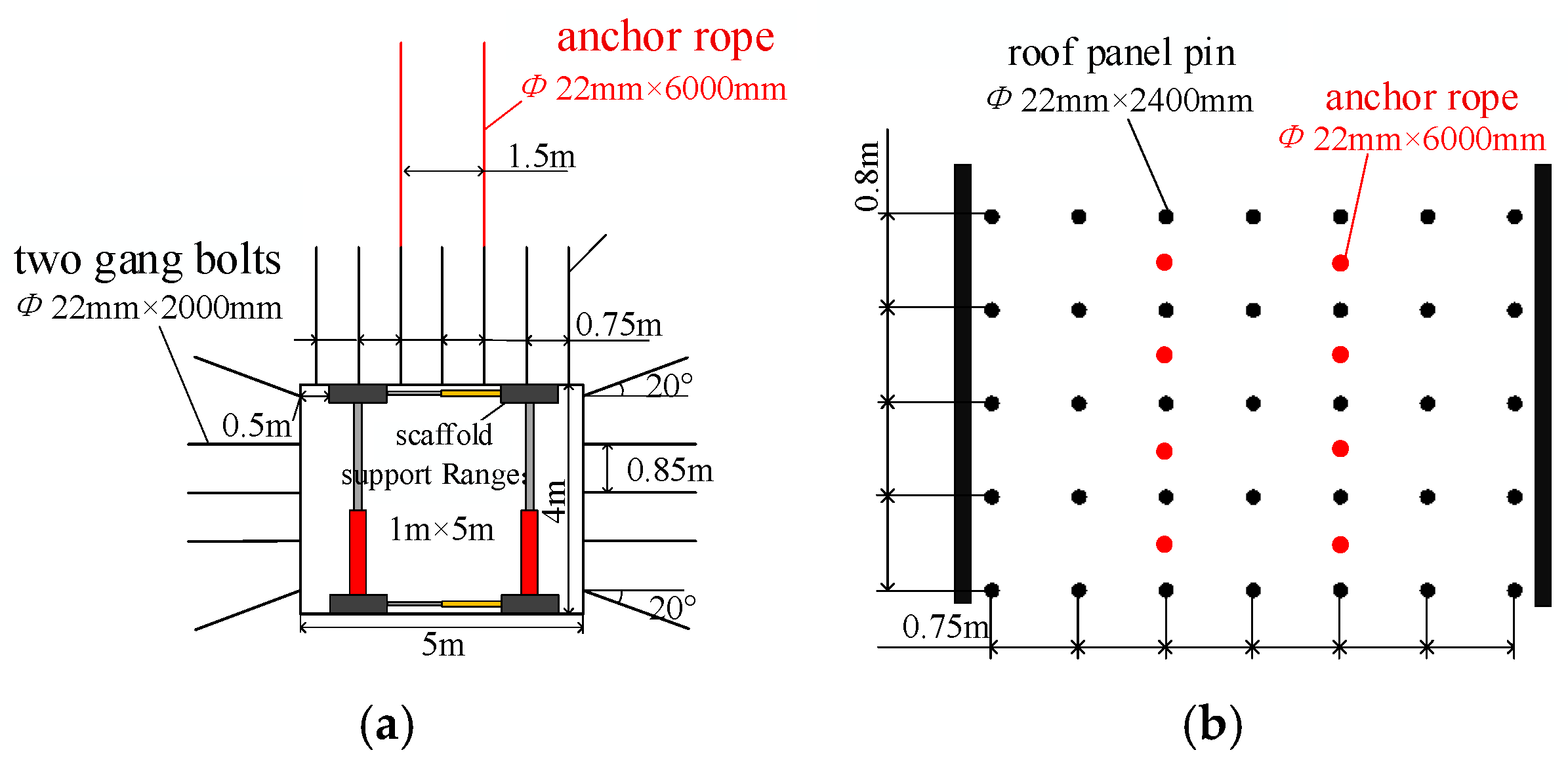
In the tunnel support arrangement, the first row of rock bolts for the roof and left rib is positioned at y = 1 m, while the first row for the right rib is at y = 6 m. The first row of roof rock bolts begins at y = 1.5 m. The roof features seven left-hand threaded resin anchor bolts (Φ 22 × 2400 mm) per row without longitudinal reinforcement, spaced at 750 mm × 800 mm intervals. One anchor cable (Φ 22 mm × 6000 mm) is installed on each side of the tunnel roof centerline at 750 mm intervals. Each sidewall row shall have five Φ 20 × 2000 mm bolts. The first bolt shall be drilled no more than 200 mm below the roof surface at a 20° upward angle. The second to fourth bolts shall be drilled vertically into the coal face at 850 mm intervals. The fifth bolt shall be drilled at a 20° downward angle relative to the horizontal. The anchor rod and cable are anchored at the end farthest from the roadway, with a fixed-to-free-length ratio of 2:1. The free ends of the anchor rod and cable are connected to a support plate, which measures 500 mm × 500 mm in the model. The mechanical parameters of the anchor rod and cable are shown in Table 2.
The advance roadway support configurations and anchor rod/cable layouts are shown in Figure 3a,b. Assuming identical support strengths on both sides of the hydraulic props, the advance tunnel model employs four 1 m × 5 m surfaces to simulate consistent support strength. Stress application achieves roof and floor support functions: two roof simulation surfaces are spaced 3 m apart along the x-axis, with the placement range at x = 10.5–11.5 m, 13.5–14.5 m, y = 5.5–10.5 m, and z = 17 m. Stress is applied in the positive z-direction to simulate roof support force. Two bottom surface simulation planes share the same x and y ranges as the roof surface, positioned at height z = 13 m. Negative z-axis stress is applied to simulate the bottom surface reaction force.

3. Results and Discussion

Excessively low or high initial support force of the advance hydraulic support may cause over-support or under-support of the roadway roof and cannot effectively complement the active support provided by rock bolts and rock bolts. To explore the reasonable range of initial support force, analyses were conducted on roadway roof displacement and the stresses experienced by rock bolts and rock bolts under different support strengths.

3.1. Analysis of Roof Displacement in Roadways Under Different Support Strengths

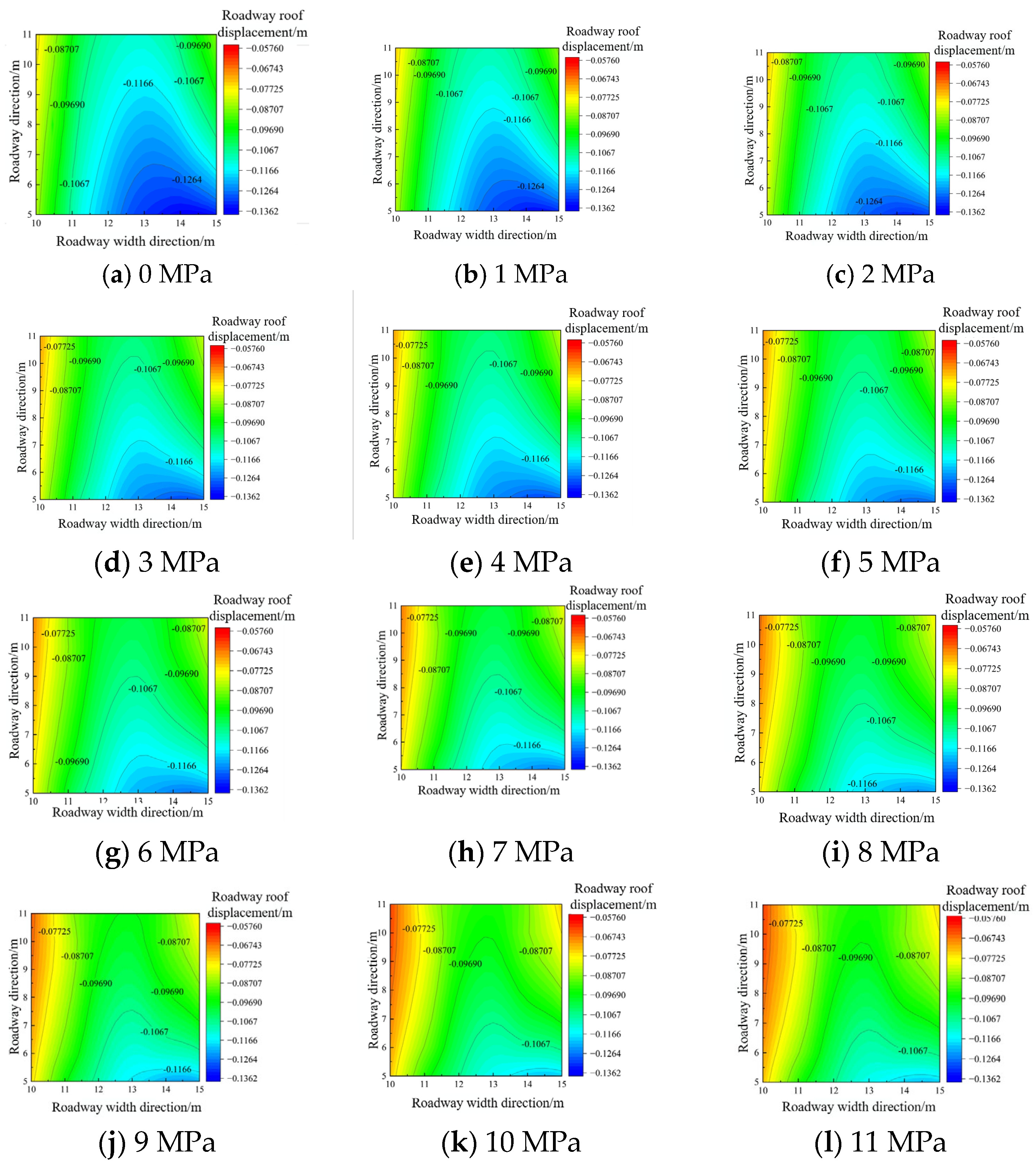
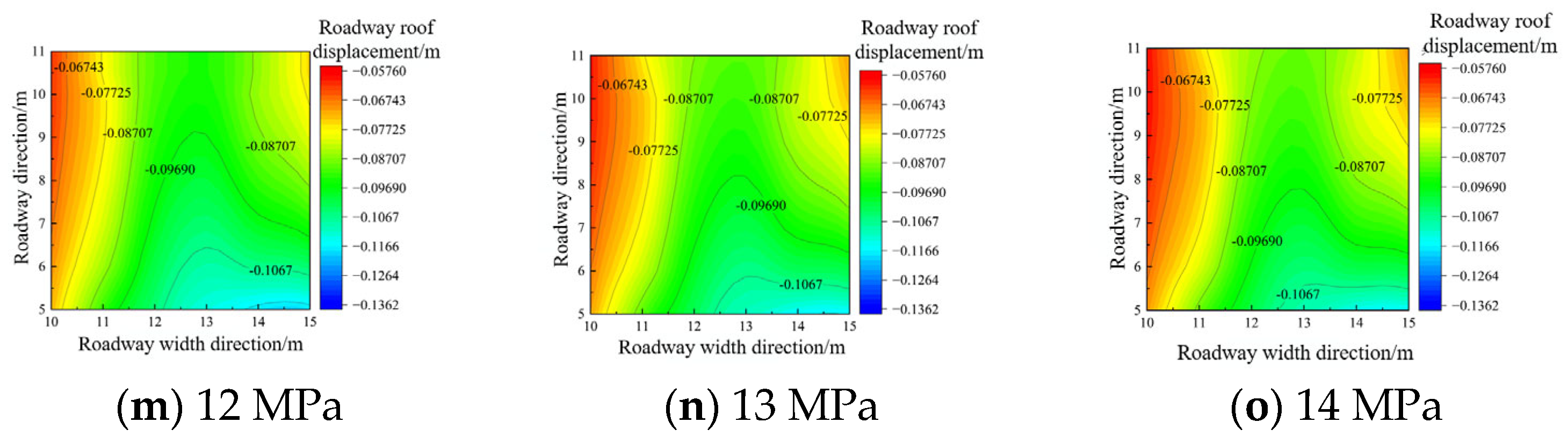
Based on the commonly used support strengths of advance hydraulic supports in actual operations, this analysis examines the roof displacement of a roadway under coupled support with hydraulic supports (0–14 MPa) and rock bolts/cables. Starting from the working face (y = 5 m), displacement measurements were taken at various positions along the roadway strike direction at the roadway roof. The displacement contour plot is shown in Figure 4. The x-axis represents the tunnel width direction, the y-axis represents the tunnel strike direction, and the z-axis represents the displacement magnitude of the tunnel roof. The color gradient of the contour map directly reflects variations in displacement magnitude, revealing the relationship between the “spatial distribution pattern” of displacement and the “response relationship to support strength.”
Within the low-support-strength range (0–3 MPa), the cloud map exhibits a pronounced color gradient characterized by “deep colors in the center and light colors at the edges.” Along the width of the roadway, displacement in the core area of the tunnel width reached 0.11–0.14 m, while displacement near the tunnel walls was only 0.08–0.10 m. The displacement difference between the core and edge zones was 0.03–0.06 m, forming a “bulging-type subsidence.” Along the tunnel strike direction, colors in local areas were darker than at both ends, indicating fluctuating displacement along the path. The mechanical essence of this feature is insufficient hydraulic support force, leading to “free deformation” of the roof rock mass. Without the constraint of rib rock, stress release is more complete in the center area, making it prone to rock layer separation and posing a higher risk of local roof falls. Entering the medium-support-strength range (3–10 MPa), the color gradient on the cloud map significantly flattens. The “center-edge” displacement difference decreases from 0.06 m to 0.02–0.03 m, and the displacement amplitude reduces from 0.11 m to 0.07 m. Colors along the tunnel strike direction become largely uniform, with no distinct darkened local areas. At this stage, the active radial restraint from rock bolts and cables synergizes with the passive vertical support from hydraulic supports. Rock bolts constrain lateral rock mass movement while supports counteract vertical stresses, shifting roof deformation from “concentrated” to “uniform” patterns as the rock mass gradually enters a stable adjustment phase. In the high-support-strength range (10–14 MPa), the cloud map exhibits overall “light and uniform” characteristics across the entire area. No significant color gradient differences are observed either across the width or along the strike direction of the roadway. Displacement across the entire area is concentrated between 0.05 and 0.07 m, with displacement differences between the center and sides of the tunnel, as well as between the ends and the middle along the strike direction, being < 0.01 m. This represents a 64.3% reduction in displacement amplitude compared to the low-strength range. This occurs because the support strength approaches the “critical support force” of the roof rock mass, achieving dynamic equilibrium between rock stress and support force. Deformation is primarily elastic rebound, eliminating the risk of rock detachment, and the overall stability of the tunnel reaches an optimal state.
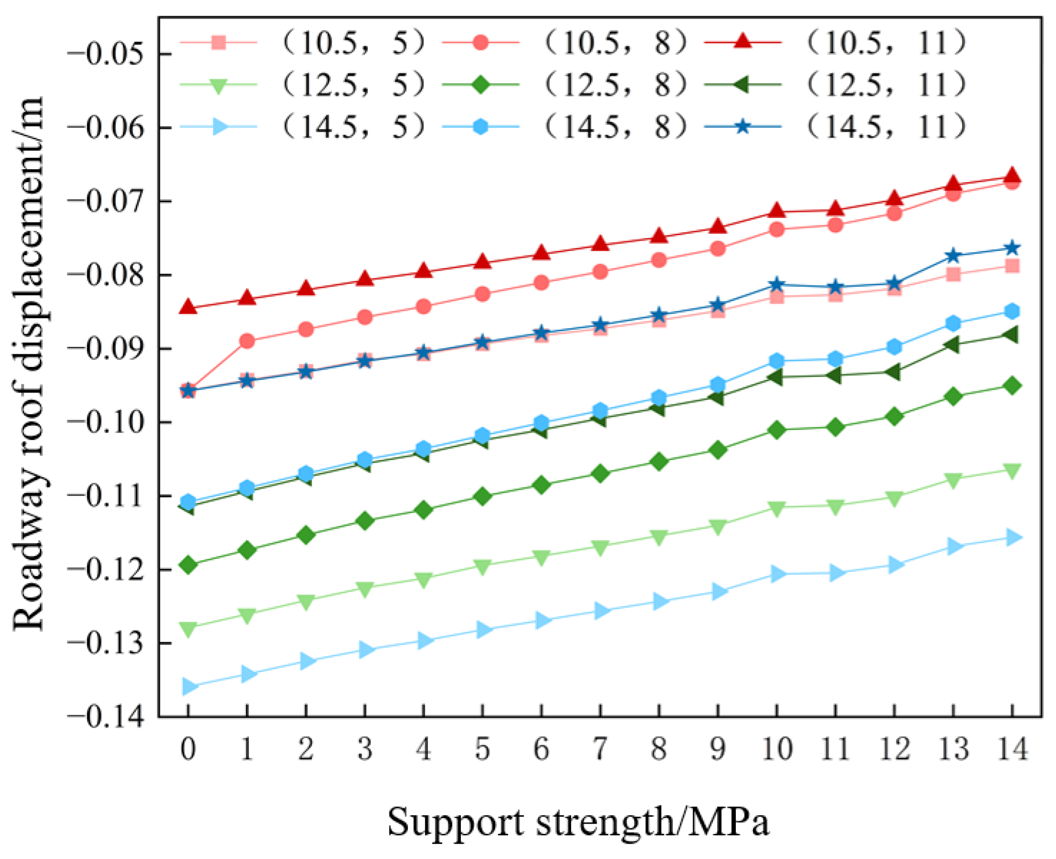
Figure 5 further illustrates displacement curves at different measurement points on the tunnel roof under varying support strengths. Within the coupled support system, increased hydraulic support strength exhibits a strict negative correlation with roof subsidence displacement. Data indicates that when support strength is 0 MPa (no hydraulic support), maximum roof subsidence reaches 0.14 m (absolute value). At this point, the combined support of bolts and cables alone struggles to counteract the self-weight stress of the roof rock and mining-induced effects, resulting in severe deformation of the surrounding rock. As the support strength gradually increases from 0 MPa to 14 MPa, the roof subsidence displacement continuously decreases. Based on displacement data across the 0–14 MPa support strength range, the roof displacement reduction process can be divided into three stages: Rapid Suppression Stage (0–10 MPa): During this phase, the hydraulic support exhibits a significant gap in support force. The roof rock mass enters a “free deformation stage,” where a modest increase in support strength rapidly fills the support gap, yielding pronounced displacement suppression effects. Upon entering the plateau phase between 10 and 12 MPa, the “marginal effect” of increasing hydraulic support strength diminishes as the surrounding rock deformation transitions into a “stable adjustment phase,” slowing the rate of displacement reduction. However, when support strength exceeds 12 MPa, the displacement curve rises further. This phenomenon arises because the support mechanism undergoes a qualitative shift from passively controlling rock failure to actively optimizing the rock bearing system.

3.2. Numerical Model Establishment

Based on coal mining engineering contexts, the mechanical properties and geological occurrence conditions of roadway surrounding rock have been clearly defined. These studies lay the foundation for roadway stability analysis. As one of the core factors influencing roadway deformation and failure [20], the distribution pattern of surrounding rock initial in situ stress directly determines the calculation accuracy of roof pressure and the reliability of support design. Therefore, this section will systematically elaborate on the composition and calculation methods of initial rock stress, providing a scientific basis for subsequent support strength design.
The formula for calculating vertical rock stress [21] is:
σ z = γ H
In the formula, σz denotes vertical stress, in Pa; γ denotes unit weight of rock and soil, typically taken as 25 kN·m−3; and H denotes burial depth, taken as 505 m.
ε x = 1 E [ σ x μ ( σ y + σ z ) ] = 0
ε y = 1 E [ σ y μ ( σ x + σ z ) ] = 0
Based on rock mechanics parameters, Poisson’s ratio μ = 0.25 is adopted (referencing empirical values for similar sandstone and mudstone, e.g., references [22,23]). In the formula, E is the elastic modulus of the roof rock layer, in Pa, and μ is the Poisson’s ratio of the rock mass.
The horizontal stress components σx and σy can be obtained as:
σ x = σ y = μ 1 μ σ z = μ 1 μ γ H
Based on Equations (1)–(4), the vertical stress σz in the surrounding rock is 12.625 MPa, while the horizontal stresses σx and σy are both 19.3 MPa.

3.3. Analysis of Anchor Bolt Stress Under Different Support Strengths

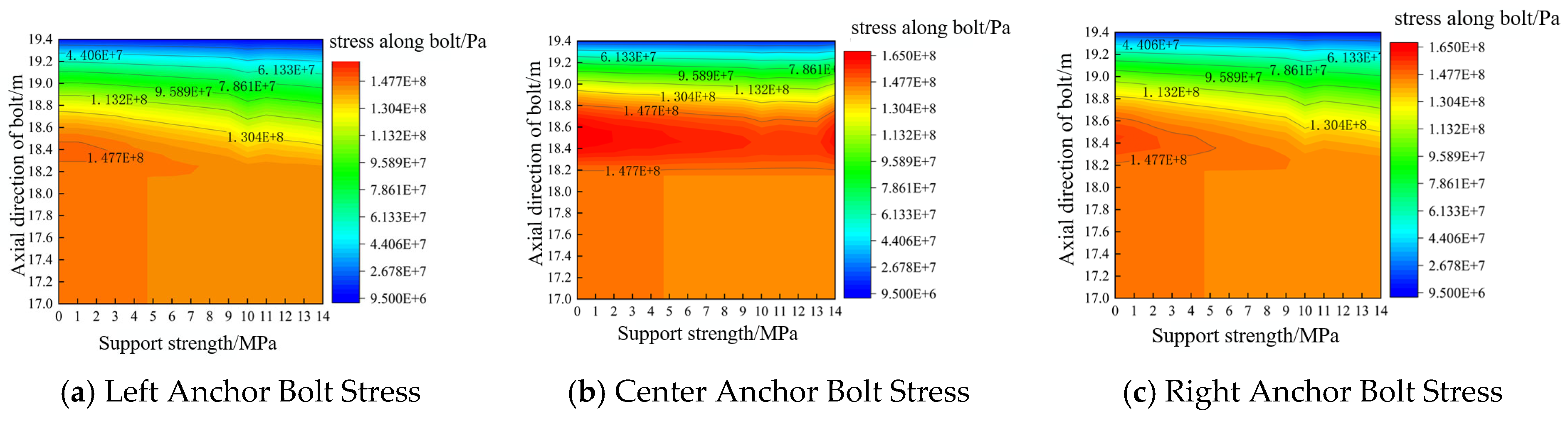
The stresses in rock bolts are affected by the varying support strengths provided by hydraulic supports. Stress data was extracted from three rock bolts in the row corresponding to the hydraulic support’s center plane (y = 7 m): the left and right bolts directly contacting the support and the bolt on the tunnel centerline. The resulting rock bolt stress contour map is shown in Figure 6.
When the support strength reached 10 MPa, the stress in the upper sections (above 18 m) of the three rock bolts showed a continuous decreasing trend: the central anchor’s corresponding region continuously declined from a peak of 1.477 × 10⁸ Pa, and the right anchor also decayed from around 1.304 × 10⁸ Pa toward lower stress ranges. The stress decay in this region exceeded 15% for all three anchors.
Figure 6 reveals distinct numerical variations and spatial patterns among the three bolts: the central bolt exhibits the highest overall stress levels, predominantly ranging from 1.304 × 10⁸ to 1.477 × 10⁸ Pa, significantly exceeding the 9.589 × 10⁷ to 1.304 × 10⁸ Pa observed for the left and right bolts. Along the rod axis, a “higher stress at the top, lower stress at the bottom” pattern emerged. The lower section (17.0–18.0 m zone) generally concentrated stresses between 2.678 × 10⁷ and 7.861 × 10⁷ Pa, while the upper section mostly exceeded 9.589 × 10⁷ Pa.

3.4. Analysis of Anchor Cable Stress Under Different Support Strengths

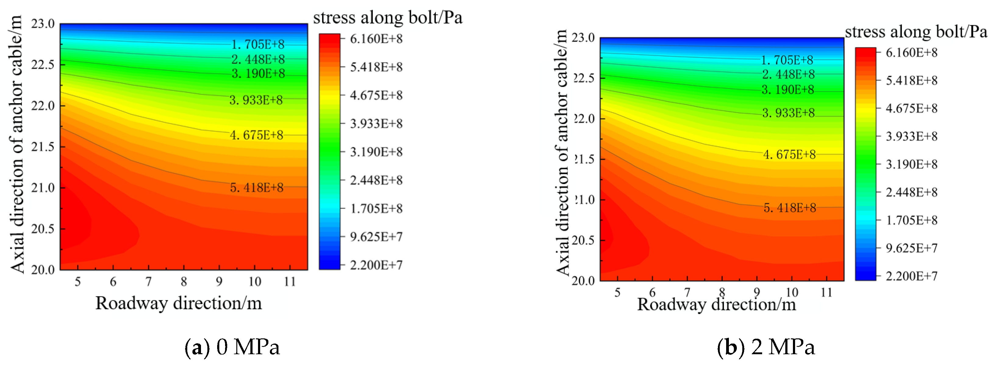
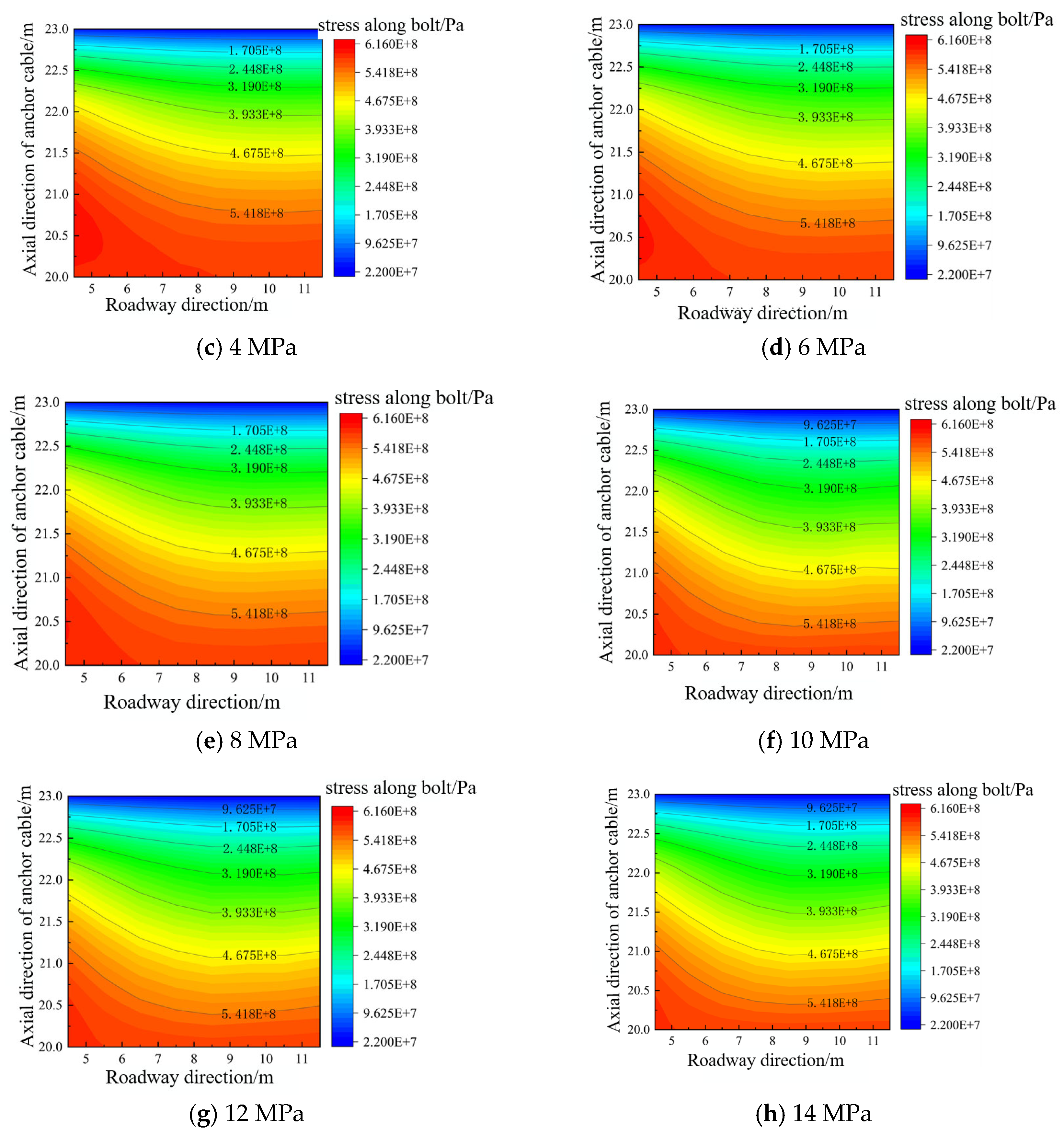
To investigate the influence of varying advance hydraulic support strengths on anchor cable stress characteristics, this study compares the distribution patterns of axial stress in anchor cables under support strengths ranging from 0 to 14 MPa. The free section of the anchor cable exhibits minimal response to support strength variations, while significant stress changes are concentrated in the anchored section. Therefore, the anchor cables on the right side of the roadway—which are significantly affected by the working face—were selected for focused analysis of their anchorage sections within the y = 4.5–11.5 m range. The distribution range and magnitude of anchor cable stresses are shown in Figure 7. The results indicate that as support strength progressively increases, both the spatial distribution pattern and peak magnitude of axial stress in the anchor cables exhibit distinct phased changes.
As the passive support strength of the advance hydraulic support increased from 0 to 14 MPa, the overall axial stress borne by the anchor cables exhibited a continuous downward trend. This indicates that the passive support gradually assumed a greater portion of the roof load, significantly alleviating the tensile load on the active support system. Stress contour lines across all eight operating conditions indicate that the stress concentration locations of the anchor cables remained largely stable, primarily concentrated in the middle section of the roadway and the upper part of the anchorage zone. However, as support strength increased, both stress amplitude and contour line gradients significantly weakened, with the area of high-stress zones gradually decreasing, demonstrating a pronounced load reduction effect.
At low passive support strengths (0–4 MPa), advance support cannot effectively bear the active displacement of the roof. The most significant subsidence occurs in the central roof area, with displacement primarily borne by the cables and bolts. This results in high and concentrated axial tensile stresses in the cables. As passive support strength increases, the roof support system can confine a portion of the roof load and displacement within itself. Through contact forces, the load is directly transferred from the roof to the support structure, thereby reducing the axial tensile force transmitted to the anchorage section. When passive support strength becomes sufficiently high (late-stage strength), further roof displacement is constrained. Anchors then bear only localized tensile forces, and stress gradients along the anchorage section flatten, indicating either an effective reduction in bonded load transfer length or more uniform load distribution.
Color distribution characteristics reveal that at low support strengths (0–2 MPa), extensive red and orange high-stress zones cover the upper half of the anchorage section and the tunnel mid-section. Maximum stresses approach the upper end of the colorbar (approximately 5–6 × 10⁸ Pa), with densely spaced contour lines indicating concentrated load bearing and rapid axial force transfer during this phase. As support strength increases to medium levels (4–8 MPa), the red zones noticeably shrink, orange gradually transitions to yellow, contour line spacing widens, and stress gradients decrease. This indicates partial roof load transfer to the support frame, resulting in a significant reduction in cable axial stress. Further increasing the support strength to the high-strength stage (10–14 MPa) causes the red high-stress zone to continue shrinking but stabilize, with slight reductions in local peaks. The high-stress areas exhibit localized characteristics, and the load reduction effect shows clear diminishing returns: beyond approximately 10 MPa, further increases in passive support strength yield limited additional load reduction for the anchor cables.
Overall, as passive support strengthens, the trend of reduced anchor cable stress is clear and exhibits phased patterns: the 0–10 MPa range represents a significant load reduction phase, while the 10–12 MPa interval enters a plateau phase where load reduction efficiency gradually diminishes. When initial support force exceeds 12 MPa, support effectiveness markedly declines, posing risks of redundant support strength. This provides crucial evidence for determining optimal hydraulic support strength.
This study reveals the staged interaction mechanism between advance passive support and active bolt–cable systems, identifying an optimal support force range (10–12 MPa) that achieves effective load sharing and minimizes roof deformation. The findings provide a quantitative basis for selecting advance support parameters in deep roadways and offer insights into active–passive coupling support design, which is of great significance for improving roadway stability and safety in deep coal mines.

4. Conclusions

Based on theoretical analysis, model development, and a numerical model of an advance-supported roadway was constructed in FLAC3D, this study systematically examined the influence of advance hydraulic support initial tension on the active support system (rock bolts and rock bolts) and the stability of roadway surrounding rock. The findings indicate the following:
(1) As the advance hydraulic support strength increases from 0 MPa to 14 MPa, the maximum roof settlement displacement shows a significant decreasing trend. The 0–10 MPa range represents the rapid suppression phase, where roof deformation is significantly reduced; the 10–12 MPa range constitutes the optimal synergistic phase.
(2) Bolts exhibit a “higher stress at top, lower stress at bottom” distribution along their length, with the highest stress occurring at the midline. When support strength reaches 10 MPa, stress in the upper sections (above 18 m) of all three bolts shows a sustained decreasing trend, with stress reduction exceeding 15% in this region for all three bolts.
(3) The support strength of the advance hydraulic support significantly influences the axial stress on the anchor cable, primarily affecting the anchored section rather than the free section. As the support strength increased from 0 to 14 MPa, the overall axial stress in the anchor cables showed a continuous downward trend. When the support strength reached approximately 10 MPa, the load reduction effect of the anchor cables stabilized, indicating that the passive support had effectively assumed the majority of the roof load.

Author Contributions

Conceptualization, D.K.; methodology, D.S.; validation, K.Z. and M.Z.; formal analysis, J.M.; investigation, M.D.; resources, J.C.; writing—original draft preparation, K.Z. and M.D.; writing—review and editing, J.M. All authors have read and agreed to the published version of the manuscript.

Funding

This work was supported by The Shandong Provincial Major Innovation Project (R&D and Industrialization of Special Mine Operation Robots) (Project No. 2025CXGC010214); The Shandong Provincial University Youth Innovation Technology Support Program (Project No. 2023KG304); and Shandong Provincial Natural Science Foundation (CN) (ZR2025QC584).

Data Availability Statement

Data is contained within the article.

Conflicts of Interest

Author Dan Kang was employed by the company Yankuang Energy Group Company Limited. The remaining authors declare that the research was conducted in the absence of any commercial or financial relationships that could be construed as a potential conflict of interest.

References

  1. Kang, H.; Wang, B.; Gao, F.; Zhang, Y.; Fan, Z.; Li, S.; Xu, X.; Chen, P. Current status and prospects of coal mining science and technology in China. GeoEnergy Commun. 2025, 1, 3. [Google Scholar] [CrossRef]
  2. Guo, F.; Zhang, N.; Xie, Z.; Han, C.; Zhang, C.; Yuan, Y.; He, Z.; Liu, J. A Three-Dimensional Supporting Technology, Optimization and Inspiration from a Deep Coal Mine in China. Rock Mech. Rock Eng. 2024, 57, 655–677. [Google Scholar] [CrossRef]
  3. Ding, K.; Wang, L.; Tian, J.; Ren, B.; Jiang, C.; Wang, S. Design of a Highly Adaptable Advance Support for a Deep, Fully Mechanized Roadway and Analysis of Its Support Performance. Appl. Sci. 2022, 12, 12728. [Google Scholar] [CrossRef]
  4. Li, Y.; Hu, D.; Zhao, J.; Kong, P.; Yang, Z.; Cai, H. Research on active advance support technology of mining roadway under hard roof condition. Sci. Rep. 2025, 15, 25172. [Google Scholar] [CrossRef] [PubMed]
  5. Su, W.; Zheng, B.; Jiang, P. Study on Anchor Cable instead of Single Hydraulic Prop Support in Advance Support of Deep Roadway. Adv. Civ. Eng. 2021, 2021, 6644832. [Google Scholar] [CrossRef]
  6. Wang, M.; Su, J.; Qin, H.; Shang, L.; Kang, J.; Liu, W.; Li, M.; Zhang, F.; Li, X.; Fang, Z. Research on Active Advanced Support Technology of Backfilling and Mining Face. Rock Mech. Rock Eng. 2024, 57, 7623–7642. [Google Scholar] [CrossRef]
  7. Singh, G.; Singh, U. Prediction of caving behavior of strata and optimum rating of hydraulic powered support for longwall workings. Int. J. Rock Mech. Min. Sci. 2009, 47, 1–16. [Google Scholar] [CrossRef]
  8. Wang, D.; He, F.; He, W.; Chen, D.; Zhang, J.; Tao, K.; Xu, C.; Wu, Y. Bearing mechanism and technical application of ventilation pipelines for disaster relief in fractured coal roadways within extra-thick coal seams. Eng. Fail. Anal. 2025, 182, 110146. [Google Scholar] [CrossRef]
  9. Zhang, X.; He, M.; Yang, J.; Wang, E.; Zhang, J.; Sun, Y. An Innovative Non-Pillar Coal-Mining Technology with Automatically Formed Entry: A Case Study. Engineering 2020, 6, 1315–1329. [Google Scholar] [CrossRef]
  10. Zhou, K.; Yu, F.; Tan, Y.; Zhao, W.; Xu, L. A Failure Mechanism of Supports in Weakly Cemented Soft Rock Roadways and the Synergistic Support Design. Rock Mech. Rock Eng. 2024, 57, 10631–10646. [Google Scholar] [CrossRef]
  11. Wang, X.; Xie, W.; Bai, J.; Jing, S.; Su, Z.; Tang, Q. Control effects of pretensioned partially encapsulated resin bolting with mesh systems on extremely soft coal gateways: A large-scale experimental study. Rock Mech. Rock Eng. 2020, 53, 3447–3469. [Google Scholar] [CrossRef]
  12. Gao, X.; Luan, Y.; Hu, C.; Lu, W.; Sun, H.; Liu, B.; Zhou, L. Study on bearing mechanism and coupling mechanism of steel arch-concrete composite structure of initial support system of large section tunnel. Geotech. Geol. Eng. 2019, 37, 4877–4887. [Google Scholar] [CrossRef]
  13. Li, C.; Xu, Y.; Chen, P.; Li, H.; Lou, P. Dynamic mechanical properties and fragment fractal characteristics of fractured coal–rock-like combined bodies in split Hopkinson pressure bar tests. Nat. Resour. Res. 2020, 29, 3179–3195. [Google Scholar] [CrossRef]
  14. Guan, E.; Miao, H.; Li, P.; Liu, J.; Zhao, Y. Dynamic model analysis of hydraulic support. Adv. Mech. Eng. 2019, 11, 1687814018820143. [Google Scholar] [CrossRef]
  15. Zhang, K.; Li, Y.; Feng, L.; Meng, X.; Zhong, D.; Huang, L. Roof deformation characteristics and experimental verification of advanced coupling support system supporting roadway. Energy Sci. Eng. 2022, 10, 2397–2419. [Google Scholar] [CrossRef]
  16. Ren, Z.; Zhang, C.; Wang, Y.; Yang, S.; Li, Q. Collaborative movement characteristics of overlying rock and loose layer based on block–particle discrete-element simulation method. Int. J. Coal Sci. Technol. 2025, 12, 17. [Google Scholar] [CrossRef]
  17. Ge, X.; Xie, J.; Wang, X.; Liu, Y.; Shi, H. A virtual adjustment method and experimental study of the support attitude of hydraulic support groups in propulsion state. Measurement 2020, 158, 107743. [Google Scholar] [CrossRef]
  18. Rong, H.; Guo, K.; Sun, D.; Luo, M.; Dong, W.; Huo, B. Research on main influencing factors and complete support technology for dynamic pressure and large deformation roadway. Sci. Rep. 2023, 13, 4136. [Google Scholar] [CrossRef]
  19. Wang, Q.; Zhang, Y.; Feng, G.; Zhu, D.; Ma, F.; Hao, W.; Li, S.; Zhang, S. Research and Application of the Calculation Method for Vertical Stress of Interlayer Rock in Coal Mining Under Pillar Goaf. Rock Mech. Rock Eng. 2025, 58, 12447–12468. [Google Scholar] [CrossRef]
  20. Liu, X.; Cleary, J.; German, G.K. The global mechanical properties and multi-scale failure mechanics of heterogeneous human stratum corneum. Acta Biomater. 2016, 43, 78–87. [Google Scholar] [CrossRef]
  21. Yuan, Y.; Verma, R. Measuring microelastic properties of stratum corneum. Colloids Surf. B Biointerfaces 2006, 48, 6–12. [Google Scholar] [CrossRef] [PubMed]
  22. Zhuge, P.; Yu, Y.; Cai, C.S.; Zhang, Z.-H.; Ding, Y. Mechanical behavior and optimal design method for innovative CFRP cable anchor. J. Compos. Constr. 2019, 23, 04018067. [Google Scholar] [CrossRef]
  23. Zhang, C.; Chen, Y.; Wu, R.; He, J.; Deng, X. Particle Size Effect and Acoustic Emission Characterization of Broken Coal Compaction and Re-Crushing. Nat. Resour. Res. 2025, 35, 553–568. [Google Scholar] [CrossRef]
Figure 1. Comprehensive bar chart of 14320 II fully mechanized mining face.
Processes 14 00770 g001
Figure 2. Surrounding rock model of roadway and arrangement of anchor rods and cables.
Processes 14 00770 g002
Figure 3. Advance roadway support form and arrangement of anchor rods and cables: (a) advance tunnel support configurations; (b) anchor rod and cable arrangement methods.
Processes 14 00770 g003
Figure 4. Cloud map of roadway roof displacement under different support strengths.
Processes 14 00770 g004aProcesses 14 00770 g004b
Figure 5. Displacement of roadway roof under different support strengths.
Processes 14 00770 g005
Figure 6. Stress cloud map of roadway roof rock bolt.
Processes 14 00770 g006
Figure 7. Stress range and size distribution of anchor cable.
Processes 14 00770 g007aProcesses 14 00770 g007b
Table 1. Physical and mechanical parameters of surrounding rock.
NameDensity
/(kg·m−3)
Bulk Modulus
/GPa
Shear Modulus
/GPa
Tensile Strength
/MPa
Cohesive Force
/MPa
Internal Friction Angle/°
Siltstone26002.871.483.287.6525.7
Mudstone23800.310.140.081.628
Coal Seam 313000.880.430.642.1337.4
Siltstone26002.871.480.335.5642.9
Interbedded siltstone and fine sandstone258017.569.542.5114.3139.5
Table 2. Mechanical parameters of anchor cables and bolts.
ParametersAnchor RodAnchor Cable
Anchorage SectionFree SectionAnchorage SectionFree Section
Modulus of elasticity/Pa200 × 109200 × 109200 × 109200 × 109
Tensile strength/Pa5 × 1085 × 1085 × 1085 × 108
Cross-sectional area/m23.79 × 10−43.79 × 10−43.79 × 10−43.79 × 10⁻⁴
Density/kg·m−37580758075807580
Grout stiffness/Pa2 × 10712 × 1071
Grout cohesion/Pa8.8 × 10518.8 × 1051
Grout layer perimeter/mm69.169.1
Pre-tension force/kN55220
Disclaimer/Publisher’s Note: The statements, opinions and data contained in all publications are solely those of the individual author(s) and contributor(s) and not of MDPI and/or the editor(s). MDPI and/or the editor(s) disclaim responsibility for any injury to people or property resulting from any ideas, methods, instructions or products referred to in the content.