1. Introduction
Tahe Oilfield, the largest marine carbonate oil and gas field in terms of reserves in China, has seen its exploration and development activities extend deep into the complex strata of the Tabei Uplift in the Tarim Basin. The area is dominated by Middle–Lower Ordovician carbonate formations, in which reservoir space is primarily of the fracture–vug type, generally characterized by great burial depth, low porosity and low permeability, and extremely strong heterogeneity [
1,
2,
3,
4]. This unique reservoir architecture, coupled with the widespread occurrence of high-temperature and high-pressure conditions, poses unprecedented challenges to drilling operations. Complex drilling problems, such as lost circulation and pipe sticking, occur with a high frequency, severely restricting the safe and efficient development of oil and gas resources [
5]. Statistics show that over the past five years, the lost-circulation rate of drilled wells has reached as high as 91%, with an average loss volume of 561 m
3 per well. This not only significantly increases operational costs but also causes irreversible damage to the reservoir. Therefore, the development and application of drilling fluid technologies capable of effectively coping with complex geological conditions such as high temperature, high pressure, and well-developed fractures and vugs have become crucial for ensuring safe drilling and improving development efficiency in the Tahe Oilfield.
In traditional drilling engineering practice, water-based drilling fluids typically rely on solid particles such as bentonite and barite to provide the required rheological properties and weighting capacity [
6,
7,
8]. However, during drilling operations, these solid particles tend to form relatively thick filter cakes on the wellbore wall or reservoir surface, leading to pore plugging, permeability reduction, and even the induction of more severe downhole complications such as wellbore collapse, hole shrinkage, and pipe sticking [
9,
10]. More critically, under the high-temperature and high-pressure conditions of the Tahe Oilfield, the stability of these solid particles deteriorates dramatically, making them prone to aggregation, sedimentation, or thermal degradation, thereby further compromising the overall performance of the drilling fluid [
11,
12,
13]. In view of the inherent limitations of traditional technical systems, the pursuit of an alternative drilling fluid system that integrates low formation damage, high efficiency, and strong inhibition has become an urgent demand and a core direction of technological development in the industry.
The Tahe Oilfield, located in the arid inland region of Xinjiang within the Eurasian continent, faces significant water scarcity due to the region’s dry climate, with an average annual precipitation of only about 150 mm. Water scarcity has become a major factor constraining local socioeconomic development and oilfield operations [
14]. Petroleum production processes, especially during the drilling and waterflooding stages, consume enormous amounts of water and generate large volumes of produced water [
15]. If such produced water is discharged directly without proper treatment, it can cause serious environmental pollution and incur high treatment costs [
16]. Therefore, utilizing pretreated oilfield water as the base fluid for drilling operations offers significant advantages in terms of cost reduction, efficiency improvement, and environmental protection.
To address these challenges, this study focuses on the development of a brine-based, solids-free drilling fluid system using produced oilfield water directly as the base fluid. This approach not only reduces the demand for freshwater but also utilizes locally available oilfield water, thus eliminating the need for long-distance transportation. As a result, it reduces both operational costs and environmental impact.
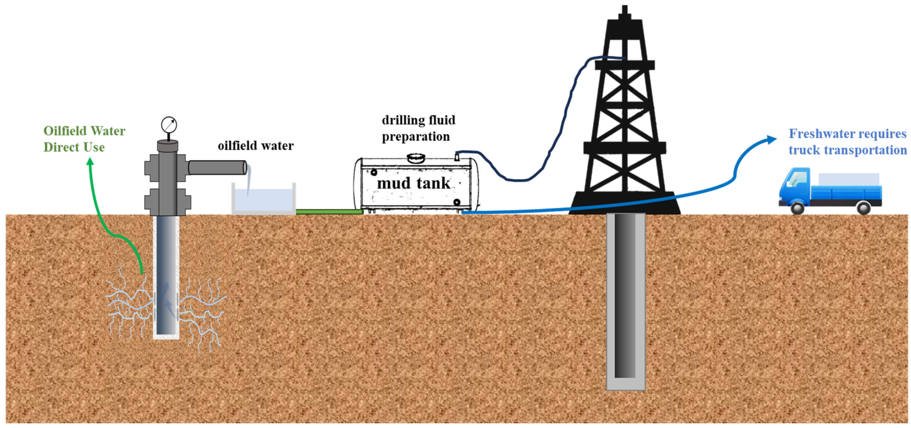
Figure 1 illustrates the contrast between two water management methods: using produced oilfield water directly at the wellsite versus transporting freshwater by truck. The system that utilizes produced water directly from the wellsite avoids the environmental costs associated with water transportation, showcasing significant potential for improving water usage efficiency in drilling operations.
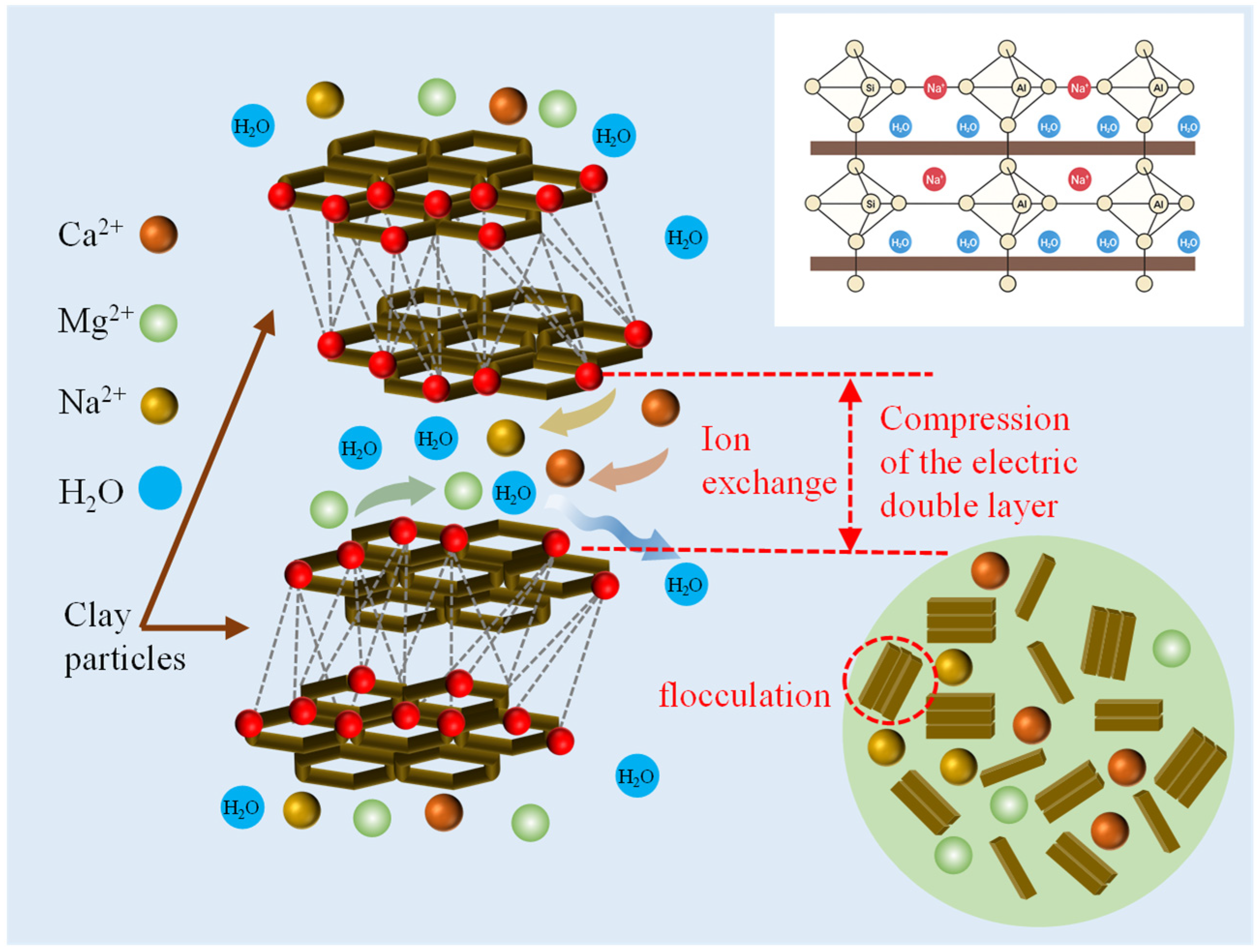
When conventional bentonite-containing drilling fluids are prepared using such highly saline water (as shown in
Figure 2), multivalent cations enter the interlayers of bentonite via cation exchange, compress the electrical double layer, inhibit its hydration and swelling, and act as “bridging agents” to promote the flocculation and settling of clay particles [
13,
17,
18,
19]. This ultimately leads to a decrease in drilling fluid viscosity and a dramatic increase in fluid loss, rendering the performance completely inadequate for operational standards [
20,
21].
However, it should be noted that most existing solids-free (non-solid-phase) brine drilling fluid systems reported in the literature are formulated and evaluated predominantly with fresh water or low-mineralization water as the base fluid [
22,
23,
24,
25,
26,
27,
28,
29]. In such relatively “clean” aqueous media, polymeric viscosifiers and fluid-loss additives can maintain hydration, chain conformation, and adsorption/film-forming capability, thereby delivering stable rheology and filtration control [
30,
31,
32]. In contrast, produced oilfield water from Tahe is highly mineralized and contains abundant dissolved salts and multivalent ions, which may strongly interfere with polymer performance through charge screening, complexation/bridging, salting-out effects, and even precipitation [
33,
34,
35,
36], leading to a partial or complete loss of functionality. Therefore, a key research gap remains: how can a robust solids-free drilling fluid system be constructed that can directly use highly mineralized produced water as the base fluid while retaining acceptable rheological stability and fluid-loss control? Addressing this gap, the novelty of the present work lies in developing and verifying an oilfield-water-based solids-free brine drilling fluid system via the systematic screening and synergistic optimization of compatible additives, enabling on-site utilization of produced water and reducing reliance on transported fresh water under the high-temperature, high-salinity conditions of the Tahe Oilfield.
3. Results and Discussion
3.1. Optimization of Key Additives
3.1.1. Pretreatment of Oilfield Water
In the experiment, the produced oilfield water used has a high mineralization and complex ionic composition. Directly using the oilfield water to prepare the drilling fluid may adversely affect the dissolution and performance of the polymer additives.
Table 1 shows the water quality parameters of the untreated oilfield water, including total salinity and concentrations of various ions. Due to the impact of these ions on the additives, the oilfield water must be pretreated to meet the requirements for the formulation of solids-free drilling fluids.
To evaluate the performance of oilfield water as a base fluid,
Table 2 compares the performance differences between untreated oilfield water and fresh water using the same drilling fluid formulation. The results show that, in untreated oilfield water, the rheological properties, fluid loss, and other performance indicators of the drilling fluid significantly decreased, failing to meet operational requirements. This is due to the high concentrations of Ca
2+ and Mg
2+ in the oilfield water, which, through ion exchange, disrupt the structure of bentonite and other polymers in the drilling fluid, leading to a decrease in viscosity and an increase in fluid loss. In contrast, the drilling fluid formulated with fresh water maintains stable performance, with good rheological properties and effective fluid loss control.
To improve this situation, we added an appropriate amount of NaOH to the oilfield water for pretreatment, adjusting the pH of the system to the required alkaline conditions. This helps inhibit the hydrolysis of metal ions, reduces the impact of multivalent ions on the polymers, and improves the dissolution efficiency of the polymers. After adding NaOH, the oilfield water was thoroughly stirred to ensure uniform mixing and then allowed to settle and clarify before being reserved for subsequent use, ensuring that the water quality met the requirements for further processing.
3.1.2. Optimization of Viscosifiers
Considering the complex geological conditions of the Tahe Oilfield, the viscosity of the solids-free system mainly depends on regulation by viscosifiers due to the absence of base viscosity provided by bentonite. In this context, four viscosifiers—CMC-HV, PAC-HV, POLY-V, and xanthan gum—were screened under high-salinity conditions. As shown in
Table 3, the experimental formulations and performance comparisons are presented. The formulation used was: 400 mL of oilfield water + 0.3% NaOH + 0.25% Na
2CO
3 + 25% NaCl, with a drilling fluid density of 1.15 g/cm
3, aged at 130 °C for 16 h. The experimental results are summarized in
Table 3.
According to the experimental results (
Table 3), under high-temperature and high-salinity conditions, the performance of the four viscosifiers (CMC-HV, PAC-HV, POLY-V, and xanthan gum) exhibited significant differences. Among them, CMC-HV showed a sharp drop in viscosity to 5 mPa·s, and its yield point reduced to zero after hot-rolling, indicating very poor thermal stability. Both PAC-HV and xanthan gum also experienced significant declines in viscosity and yield point after aging, decreasing to 2.5 mPa·s and 17 mPa·s, with YP/PV ratios dropping to 0.25 and 0.55, demonstrating insufficient temperature and salt resistance. In contrast, POLY-V exhibited excellent stability before and after hot-rolling, with apparent viscosity decreasing from 57.5 mPa·s to 39.5 mPa·s, yield point remaining at 19.5 Pa from 38.5 Pa, and its YP/PV ratio was maintained at 0.98, achieving the best overall performance. Therefore, under the complex geological conditions of the Tahe Oilfield, POLY-V is the preferred viscosifier for solids-free systems due to its superior temperature and salt resistance as well as rheological stability.
3.1.3. Optimization of Fluid-Loss Additives
As a highly saline onsite water source containing significant amounts of Ca2+, Mg2+, Cl−, and SO42−, oilfield water offers advantages such as wide availability and cost-effectiveness, but its complex ionic composition poses challenges to drilling fluid performance, including flocculation and precipitation, increased fluid loss, and unstable rheological properties. Therefore, the optimization of fluid-loss additives in oilfield water-based drilling fluid formulations is a key step to enhancing field applicability.
Ten oilfield-water drilling-fluid formulations with different fluid-loss additives were designed and tested to investigate their rheological properties, fluid-loss control performance, and hot-rolling stability under high-temperature conditions. The base formulation for the oilfield water system was: 400 mL oilfield water + 0.3% NaOH + 0.25% Na
2CO
3 + 0.7% POLY-V viscosifier + 25% NaCl. Through systematic comparison and analysis, the fluid-loss additive with the best overall performance was preliminarily selected (
Table 4).
In terms of rheological properties, the formulation containing 2.0% DEG-FLO + 1.5% STAR-AM exhibited a pre-hot-rolling apparent viscosity of 48 mPa·s, plastic viscosity of 21 mPa·s, yield point of 27 Pa, and YP/PV ratio of 1.286, indicating good carrying capacity and shear-yield performance. After hot rolling, the system still maintained a high apparent viscosity (46.5 mPa·s) and plastic viscosity (24 mPa·s), with a yield point of 22.5 Pa and a YP/PV ratio of 0.938, demonstrating strong structural stability, minimal degradation of the colloidal network, and excellent thermal resistance.
Regarding fluid-loss performance, this formulation showed an API fluid loss of 2 mL and an HTHP fluid loss of 17 mL, both the lowest among all tested formulations, outperforming most other systems. This indicates that the formulation can rapidly form a dense filter cake during drilling, effectively blocking fluid invasion into the formation, and exhibiting superior fluid-loss control. A comparison of the pre- and post-hot-rolling parameters shows minimal changes in apparent viscosity, plastic viscosity, and yield point, suggesting good thermal stability and shear resistance, making the formulation suitable for high-temperature, high-salinity downhole conditions.
Therefore, considering the overall performance in terms of rheology, fluid-loss control, and post-thermal stability, the formulation of oilfield water + 0.3% NaOH + 0.25% Na2CO3 + 0.7% POLY-V viscosifier + 2.0% DEG-FLO + 1.5% STAR-AM + 25% NaCl exhibited the most balanced and excellent performance within the oilfield water system. This formulation is recommended as the key candidate for subsequent optimization studies and field application validation.
3.1.4. Optimization of Lubricants
To optimize the lubricating performance of the oilfield water-based drilling fluid system, two commercial lubricants—ATV-SLIP and JHB-SLIP—were selected and added to the base drilling fluid at a mass fraction of 2% each. Their effects on the rheological and lubricating properties of the system were investigated. The drilling fluid formulation was: 400 mL oilfield water + 0.3% NaOH + 0.25% Na
2CO
3 + 0.7% POLY-V + 2.0% DEG-FLO + 1.5% STAR-AM + 25% NaCl. Relevant performance parameters are listed in
Table 5.
As shown in
Table 5, the two lubricants had little effect on the apparent viscosity, plastic viscosity, yield point, and YP/PV ratio of the drilling fluid, and the overall rheological properties of the system remained stable. Specifically, after adding ATV-SLIP, the drilling fluid exhibited apparent viscosities of 46 mPa·s and 47 mPa·s before and after hot-rolling, respectively, with plastic viscosities of 20 mPa·s and 25 mPa·s. After adding JHB-SLIP, the corresponding values were 49 mPa·s and 44 mPa·s for apparent viscosity, and 23 mPa·s and 24 mPa·s for plastic viscosity. The differences in rheological performance between the two lubricants were not significant, and neither caused a noticeable increase or decrease in system viscosity, indicating that both lubricants have good compatibility and dispersion stability in this solids-free brine-based system.
However, in terms of lubricating performance, the two lubricants showed significant differences.
Figure 3 presents the extreme pressure lubrication coefficient (EP Lubrication Coefficient) test results for different additive systems. The blank system had a lubrication coefficient of 0.16, which decreased to 0.13 after adding 2% ATV-SLIP, and to 0.14 after adding 2% JHB-SLIP. This indicates that ATV-SLIP exhibits superior lubrication under extreme pressure conditions, reducing the lubrication coefficient by 18.75% compared with the blank system and by 7.14% compared with JHB-SLIP, demonstrating a more pronounced lubricating effect. In contrast, the poly-sulfonate high-performance low-friction system showed a lubrication coefficient of 0.19, higher than that of the oilfield water system without any lubricant, indicating that this system also possesses relatively good lubricating performance.
In addition, it is worth noting that although JHB-SLIP showed slightly better performance in terms of API and HTHP fluid loss compared with ATV-SLIP, the minor differences in fluid loss have a limited impact on actual drilling operations. Lubricating performance, on the other hand, is a key factor influencing drilling efficiency and wellbore stability, especially in high-stress and high-friction complex formations. Therefore, considering lubricating performance, rheological stability, and practical application requirements, ATV-SLIP was preferentially selected as the lubricant for the solids-free brine-based drilling fluid system in this study.
3.2. Performance Evaluation of Oilfield Water-Based Solids-Free Drilling Fluids
3.2.1. Formulation of Oilfield Water-Based Solids-Free Drilling Fluids
Based on the optimized selection of the viscosifier POLY-V, high-temperature and salt-resistant fluid-loss reducer DEG-FLO, plugging agent STAR-AM, and lubricant ATV-SLIP, and taking into account the geological characteristics of the Tahe Oilfield, such as high temperature, high salinity, and easily destabilized wellbores, a solids-free, environmentally friendly drilling fluid formulation suitable for oilfield water systems was developed through laboratory evaluations of rheology, fluid loss, high-temperature aging, and plugging performance. In the formulation, 0.3% NaOH and 0.25% Na2CO3 are used to adjust the system alkalinity and mitigate the effects of divalent ions; POLY-V (0.4–0.7%) ensures an appropriate YP/PV ratio and rock-carrying capacity; DEG-FLO (2.0%) forms a dense filter cake under high-temperature conditions to effectively reduce fluid loss; STAR-AM (1.5%) enhances wellbore plugging capability; and ATV-SLIP (1–2%) improves torque and friction, enhancing drilling efficiency. After comprehensive evaluation, the final solids-free oilfield water-based formulation was determined as: oilfield water + 0.3% NaOH + 0.25% Na2CO3 + 0.4–0.7% POLY-V + 2.0% DEG-FLO + 1.5% STAR-AM + 1–2% ATV-SLIP. This system is environmentally friendly, stable, and capable of meeting the drilling requirements of the Tahe Oilfield block.
3.2.2. Evaluation of Calcium Tolerance in Solids-Free Drilling Fluid Systems
In high-salinity and high-mineralization formations, calcium ions (Ca2+) are one of the main contaminants that lead to the deterioration of drilling fluid performance. As the water source for the solids-free drilling fluid in this study, oilfield water naturally contains relatively high concentrations of calcium and other multivalent metal ions, which can readily complex, precipitate, or crosslink with polymers and dispersants in the system, resulting in viscosity reduction, structural damage, and increased fluid loss. To systematically evaluate the stability of the solids-free system under calcium-contaminated conditions, different concentrations of calcium chloride (CaCl2, 0.5–3%) were gradually added to the system to simulate further increases in formation calcium ion concentration and investigate their effects on rheological and fluid-loss properties.
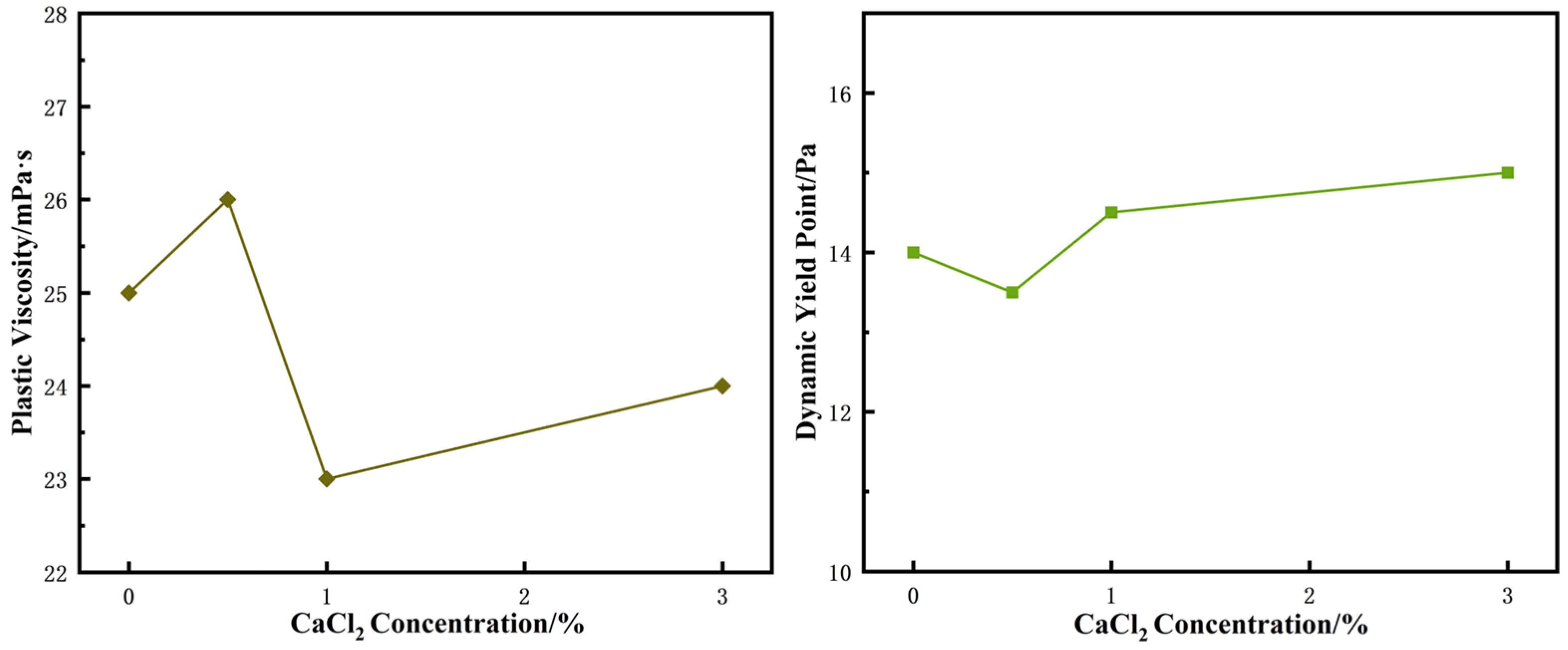
As shown in
Figure 4, as the CaCl
2 concentration increased from 0% to 3%, both the plastic viscosity (PV) and yield point (YP) of the drilling fluid exhibited nonlinear variations. The PV and YP changes reflect a common structural evolution pattern: PV increased from 25 mPa·s to 26.5 mPa·s at 0.5% CaCl
2, then decreased to approximately 23 mPa·s at 1.0%, and rose again to about 24 mPa·s at 3.0%; meanwhile, YP steadily increased from 13.5 Pa to around 15.5 Pa. Overall, low concentrations of Ca
2+ can moderately enhance the system structure through slight crosslinking or bridging effects, increasing viscosity and structural strength. When the Ca
2+ concentration exceeds 1.0%, the stability of polymers and fluid-loss additives is disrupted, causing a reduction in PV. However, further increases in salinity induce salting-out and particle aggregation, partially restoring the system structure and resulting in a rebound in both PV and YP.
These observations indicate that calcium ions have a dual regulatory effect on the system structure, capable of both strengthening and weakening it, but ultimately leading to a reconstructed stable structure at high concentrations. Notably, although PV decreases at intermediate concentrations, the continuous increase in YP demonstrates that the system still maintains good structural stability. Therefore, this solids-free system exhibits strong shear resistance and a certain degree of calcium tolerance under calcium-contaminated conditions.
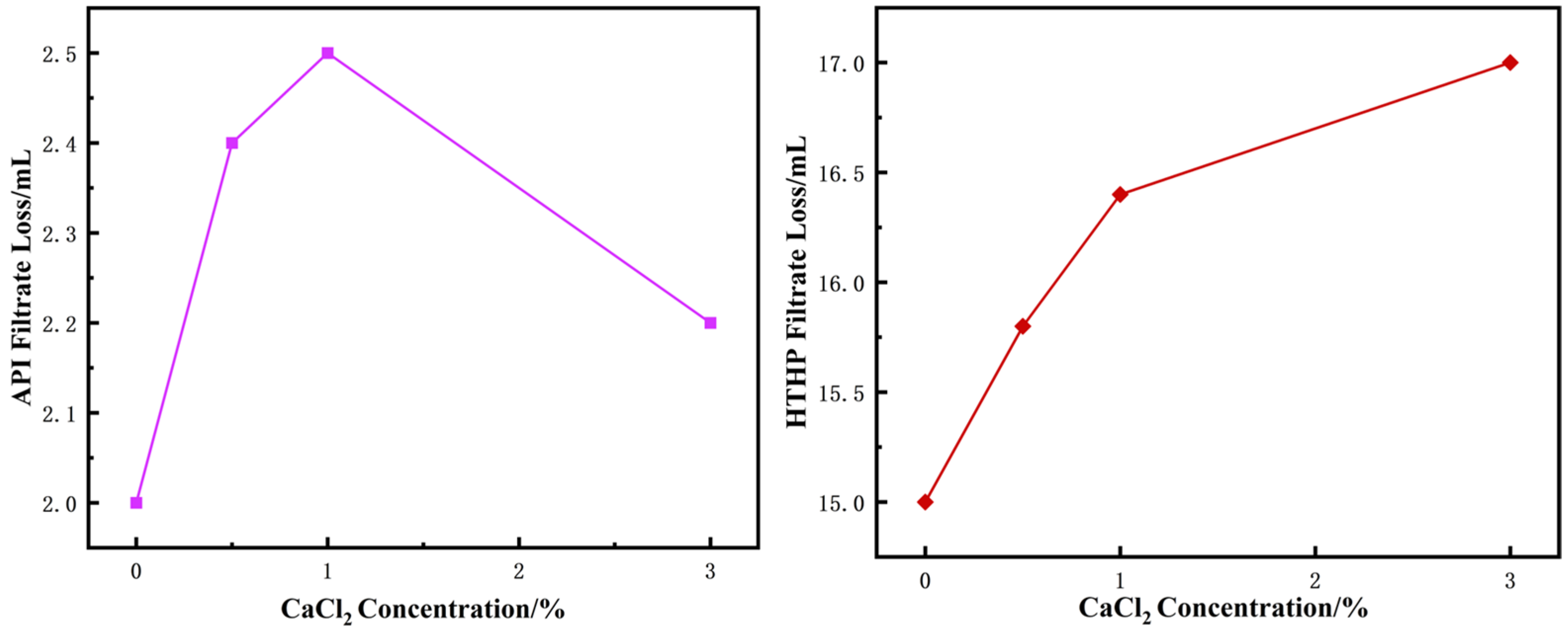
As shown in
Figure 5, with increasing CaCl
2 concentration, both the API fluid loss and HTHP fluid loss initially increased and then decreased, although the overall trend was upward.
Both API and HTHP fluid loss exhibited systematic changes reflecting structural disturbance under the influence of CaCl2. The API fluid loss reached a peak of approximately 2.5 mL at 1% CaCl2, then gradually decreased to about 2.2 mL at 3.0%, indicating that low concentrations of Ca2+ can disrupt filter cake density, while high concentrations promote re-densification of the filter cake through salting-out or crosslinking effects. In contrast, the HTHP fluid loss increased continuously from 15 mL to approximately 17.0 mL with rising CaCl2 concentration, showing a monotonically increasing trend. This suggests that under high-temperature and high-pressure conditions, Ca2+ has a more pronounced disruptive effect on polymers and filter cake structure, making it difficult to form an effective barrier even at high concentrations.
Overall, although both API and HTHP fluid loss varied to some extent, the changes were relatively minor and within acceptable ranges, indicating that the system can maintain good fluid-loss control under calcium-contaminated conditions.
3.2.3. Evaluation of Long-Term Stability of Solids-Free Drilling Fluid Systems
To systematically evaluate the structural integrity and performance decay of the developed oilfield water-based solids-free drilling fluid system during long-term storage and downhole circulation, aging stability tests were conducted at different time scales. The prepared solids-free drilling fluid was placed in aging cells and subjected to static aging at 130 °C for 3, 5, and 7 days. After aging, the rheological parameters (plastic viscosity and yield point) and fluid-loss properties of the mud at each stage were systematically measured to compare the trends of structural changes during aging. By analyzing the variations in rheological properties with aging time, the thermal stability of the polymer additives, the ability of the system to maintain its internal structure, and potential degradation behaviors can be assessed, providing a comprehensive evaluation of the long-term stability of the solids-free system and supporting its adaptability and reliability for extended downhole operations.
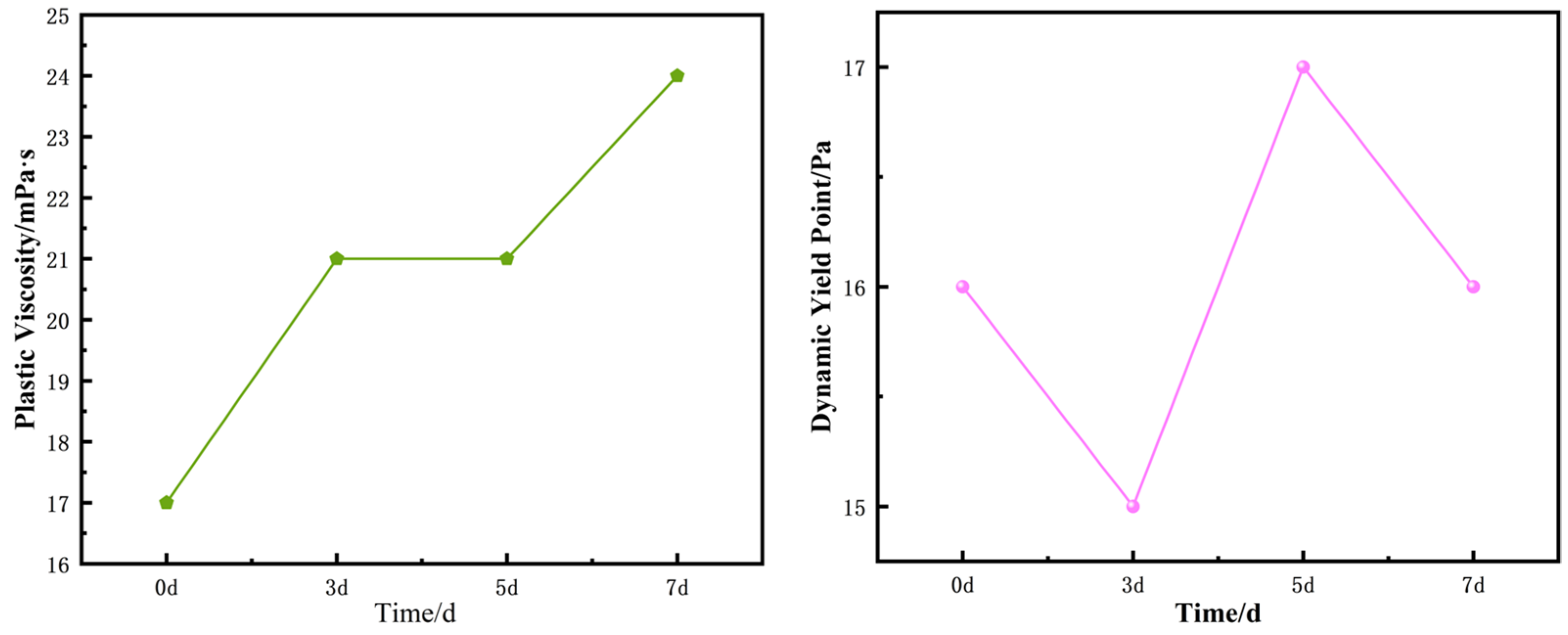
As shown in
Figure 6, with increasing aging time, the plastic viscosity (PV) and yield point (YP) of the solids-free drilling fluid system exhibited distinct dynamic trends. PV gradually increased from an initial value of approximately 17 mPa·s to about 24 mPa·s after 7 days of aging, showing an overall upward trend. This indicates that the polymers in the system may undergo crosslinking or structural densification under prolonged high-temperature conditions, resulting in a significant increase in fluid viscosity. In contrast, YP fluctuated only within the range of 15–17 Pa, remaining relatively stable and demonstrating good suspension performance during long-term static periods. Overall, the variations in both PV and YP were within a controllable range, indicating that the solids-free system can maintain good rheological structure stability under long-term aging conditions.
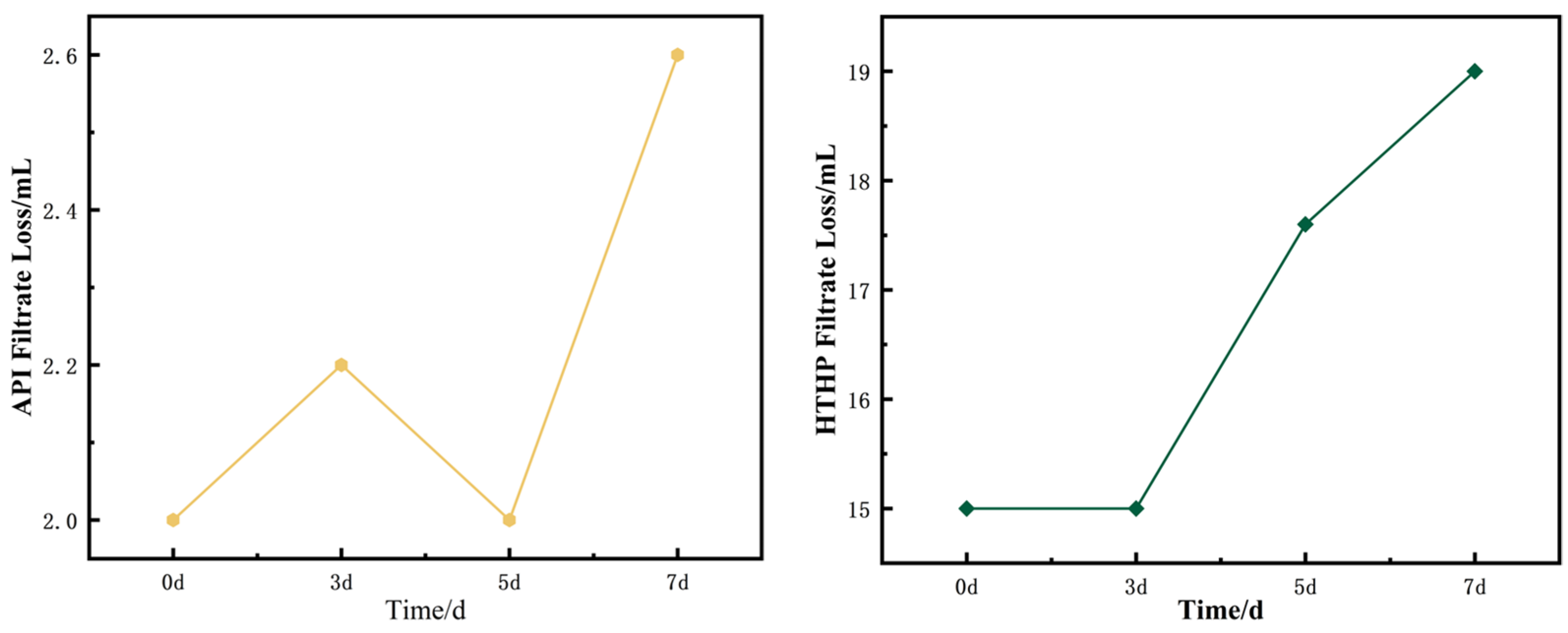
As shown in
Figure 7, the fluid-loss performance of the solids-free drilling fluid system exhibited certain fluctuations with aging time. The API fluid loss remained relatively stable at approximately 2.0–2.1 mL during 0–5 days, indicating that the system had stable film-forming and plugging ability in the early stage. However, it increased significantly to about 2.6 mL at 7 days, suggesting that prolonged high-temperature exposure may lead to partial polymer degradation or damage to the particle structure, reducing filter cake density and increasing fluid loss. The HTHP fluid loss showed a similar trend: it remained stable at approximately 15–16 mL during 0–5 days and rose to about 19 mL at 7 days, reflecting a certain decline in plugging ability under high-temperature and high-pressure conditions. Overall, the system exhibited good fluid-loss control during short-term aging, but a rising trend in fluid loss was observed under prolonged high-temperature conditions.
After 7 days of aging at 130 °C, the solids-free drilling fluid system exhibited excellent rheological performance and good structural stability. Fluid-loss increased gradually over time but still generally met the performance requirements for drilling fluids after prolonged static periods downhole.
3.2.4. Compatibility of Sulfur Scavengers in Brine-Based Solids-Free Drilling Fluid Systems
The primary purpose of introducing a sulfur scavenger into the drilling fluid system is to remove harmful gases such as hydrogen sulfide generated during drilling, thereby enhancing wellbore operational safety. However, during use, the sulfur scavenger may chemically react or physically interfere with other components in the drilling fluid, potentially affecting system stability and performance. Therefore, 1% sulfur scavenger was added to the oilfield water-based system to investigate changes in rheological properties and fluid-loss performance before and after hot rolling. The experimental results are shown in
Table 6. Zinc carbonate basic, the sulfur scavenger used, is insoluble in water but has limited solubility under alkaline conditions. When added to the solids-free drilling fluid, it exhibited slight viscosity reduction and fluid-loss control effects, without causing flocculation. This indicates that zinc carbonate basic has good compatibility with the solids-free drilling fluid system.
3.2.5. Analysis of Mud Cake Structure
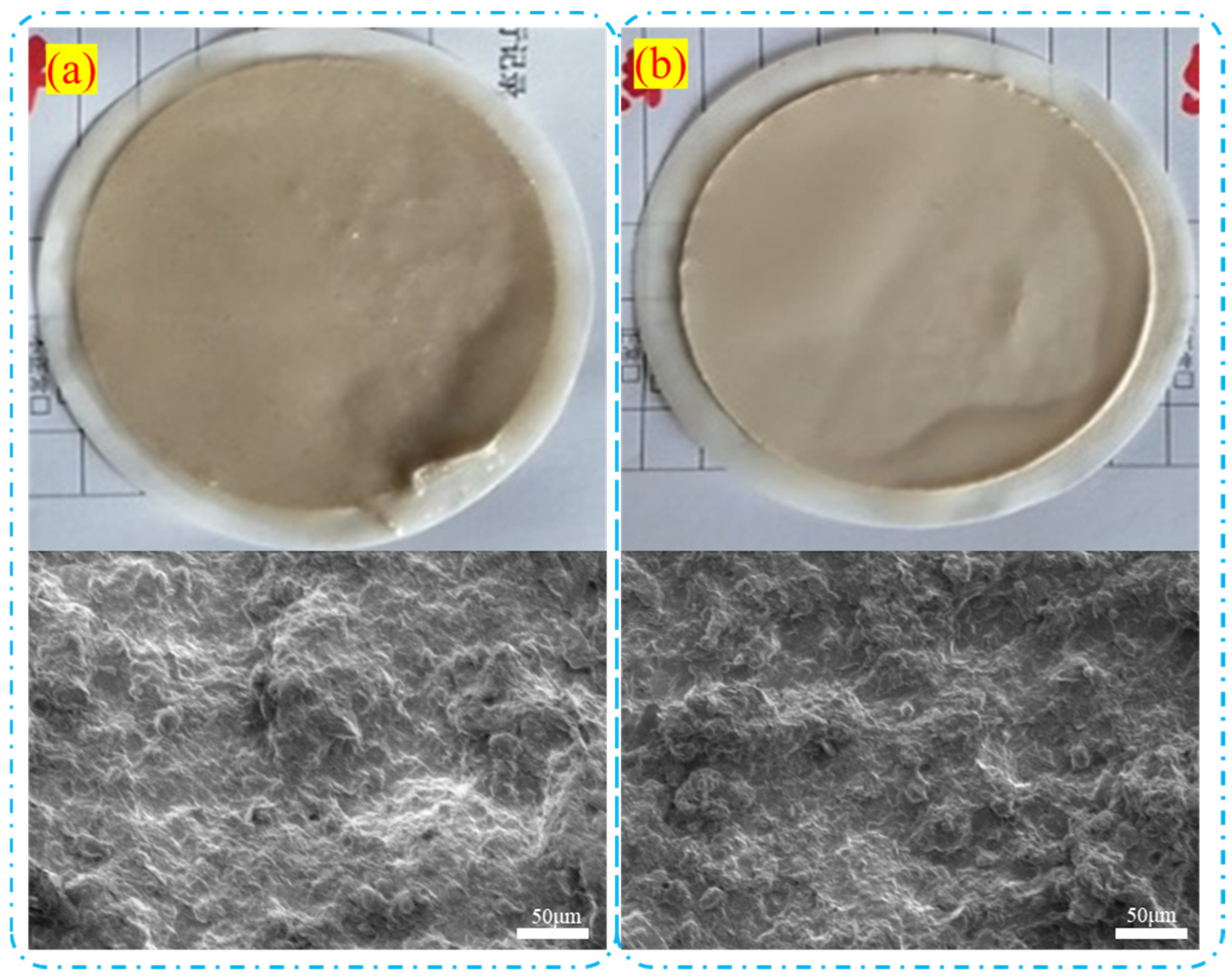
To evaluate the differences in mud cake structure formed by oilfield water and freshwater as base fluids in drilling fluids, two drilling fluids were prepared using freshwater and oilfield water, respectively, and their mud cake structures were compared. Scanning electron microscope (SEM) observations show that the mud cake formed with freshwater as the base fluid (
Figure 8) has a looser and more uneven surface with larger pores. The SEM images reveal significant gaps and irregular layering in the microstructure, indicating weaker bonding between solid particles in the freshwater-based fluid, which leads to poor mud cake stability and higher fluid loss. In contrast, when oilfield water is used as the base fluid, the mud cake surface is denser and more uniform, with noticeably smaller pores. The SEM images show a tighter microstructure, with even lamellar arrangement and stronger bonding between particles, resulting in better stability of the mud cake and significantly reduced fluid loss.
3.2.6. High-Temperature, High-Pressure Rheological Performance
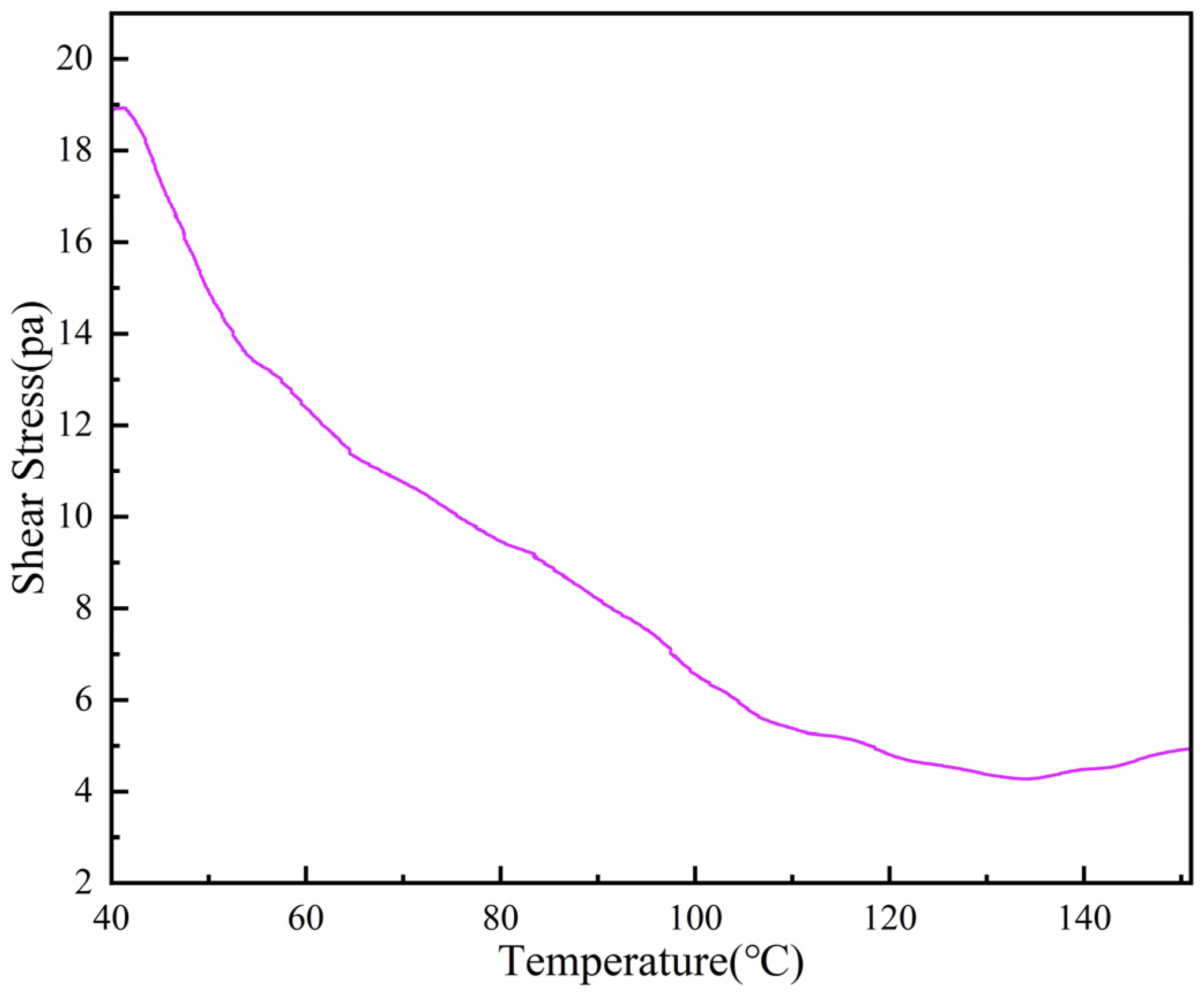
To assess the effect of high temperature on the rheological properties of the drilling fluid, a series of tests was conducted under constant pressure conditions of 80 MPa, simulating downhole temperature variations. The shear stress of the drilling fluid was measured as the temperature was increased from 40 °C to 150 °C.
Figure 9 presents the shear stress variation with temperature. As shown in the figure, there is a significant decrease in shear stress with increasing temperature, indicating the temperature sensitivity of the fluid. This trend is typical for drilling fluids, as high temperatures tend to reduce viscosity by weakening polymer interactions and enhancing fluid flow.
Even under conditions of 150 °C and 80 MPa, the system demonstrates excellent rheological stability, with performance significantly outperforming conventional bentonite-based systems under similar conditions. Although there is a certain decrease in shear stress, the system still maintains a considerable shear force (4.5 Pa) in the high-temperature, high-pressure environment, indicating that it has not completely lost its shear strength.
3.3. Field Application
To effectively address issues such as developed pores and fractures and frequent fluid loss in the Tahe carbonate reservoirs, a solids-free drilling fluid system was preferentially deployed in the field to reduce formation damage, minimize drilling fluid loss, and lower drilling costs. This system uses produced oilfield water as the base fluid and incorporates an appropriate proportion of viscosifiers, fluid-loss reducers, lubricants, and weighting materials (e.g., NaCl and limestone). By reducing the solid content and enhancing rheological properties, it achieves coordinated control of formation sealing and fluid-carrying capacity in high-permeability formations.
To date, the system has been successfully applied in 13 wells, including 11 open-hole sidetracks and two window wells, with a maximum applicable temperature of 155 °C, a maximum drilling fluid density of 1.60 g/cm3, and the longest shale section traversed reaching 72 m. On average, the drilling cycle was shortened by approximately 2.9 days, demonstrating the system’s excellent temperature adaptability and operational efficiency.
Taking well TK411CH as an example, the well was designed with a depth of 5948 m and an originally planned drilling cycle of 20 days. During the open-hole sidetrack operation, the solids-free drilling fluid system was successfully applied for the first time. To address the severe downhole fluid-loss risk, real-time monitoring and dynamic formulation adjustment were implemented, enabling continuous high-strength drilling over 211 m under loss conditions. During this process, a cumulative drilling fluid loss of 952 m3 was recorded, yet wellbore stability was consistently maintained, demonstrating the excellent wellbore sealing and fluid-loss control capability of the solids-free system.
Table 7 shows the drilling fluid performance during field application. Compared with conventional drilling fluid systems, the solids-free system significantly improved the mechanical drilling rate, increasing it from 1.87 m/h to 3.18 m/h—a more than 70% improvement—substantially shortening the operational cycle. The actual drilling cycle was reduced to only 13 days, 7 days shorter than originally planned, which not only enhanced drilling efficiency but also effectively reduced drilling fluid consumption and overall operational costs, providing reliable technical support for fast and efficient drilling in similarly challenging high-loss formations.
In addition to the TK411CH well, the data from other wells also demonstrate the stability and efficiency of the solids-free drilling fluid system under different conditions. The TK515CH well was designed with a depth of 5818.45 m, with an estimated drilling period of 20 days. The actual drilling depth reached 5845 m, and the drilling period was 20.25 days. This well applied the solids-free drilling fluid system for the first time during window drilling operations, successfully crossing a 55 m section of the Bachu Formation mudstone and limestone, with a total fluid loss of 284 m
3. During the window drilling phase, the drilling fluid performance and operational efficiency were excellent. The drilling fluid performance indicators of this well met expectations in both design and actual application, with specific data shown in
Table 8.
To further demonstrate the application effects of the drilling fluid system in different wells,
Table 9 presents the average drilling fluid performance data from 11 wells.
The performance of the solids-free drilling fluid system was evaluated across 11 wells with varying conditions. The results indicate that the system exhibits stable rheological properties and effective fluid-loss control, with densities ranging from 1.02 to 1.50 g/cm3. The plastic viscosity and yield point varied across wells, demonstrating the system’s adaptability to different geological conditions. The fluid-loss values (FLAPI and FLHTHP) remained within acceptable limits, indicating good performance under both standard and high-temperature, high-pressure conditions. Notably, the system contributed to a significant reduction in drilling cycle times, with some wells achieving a reduction of up to 8.6 days. These findings highlight the versatility and efficiency of the drilling fluid system, particularly in high-salinity, high-temperature environments, and suggest its potential for enhancing drilling efficiency in complex geological conditions.