3.1. Flow Characteristics of a Swirl Reactor
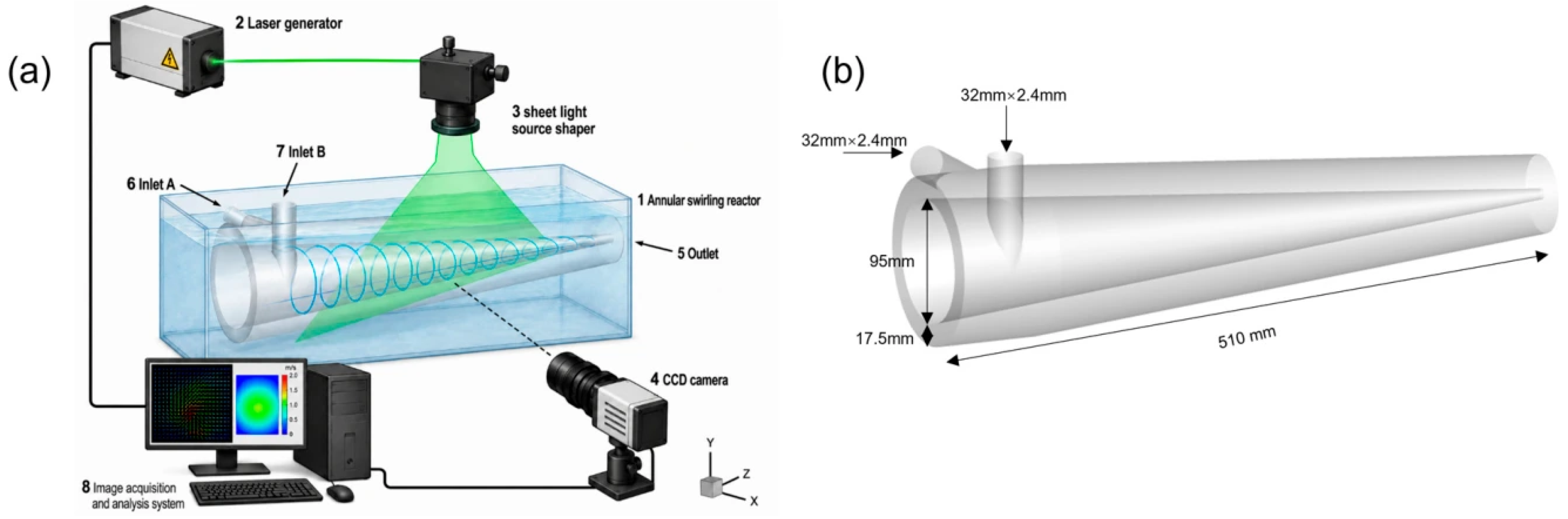
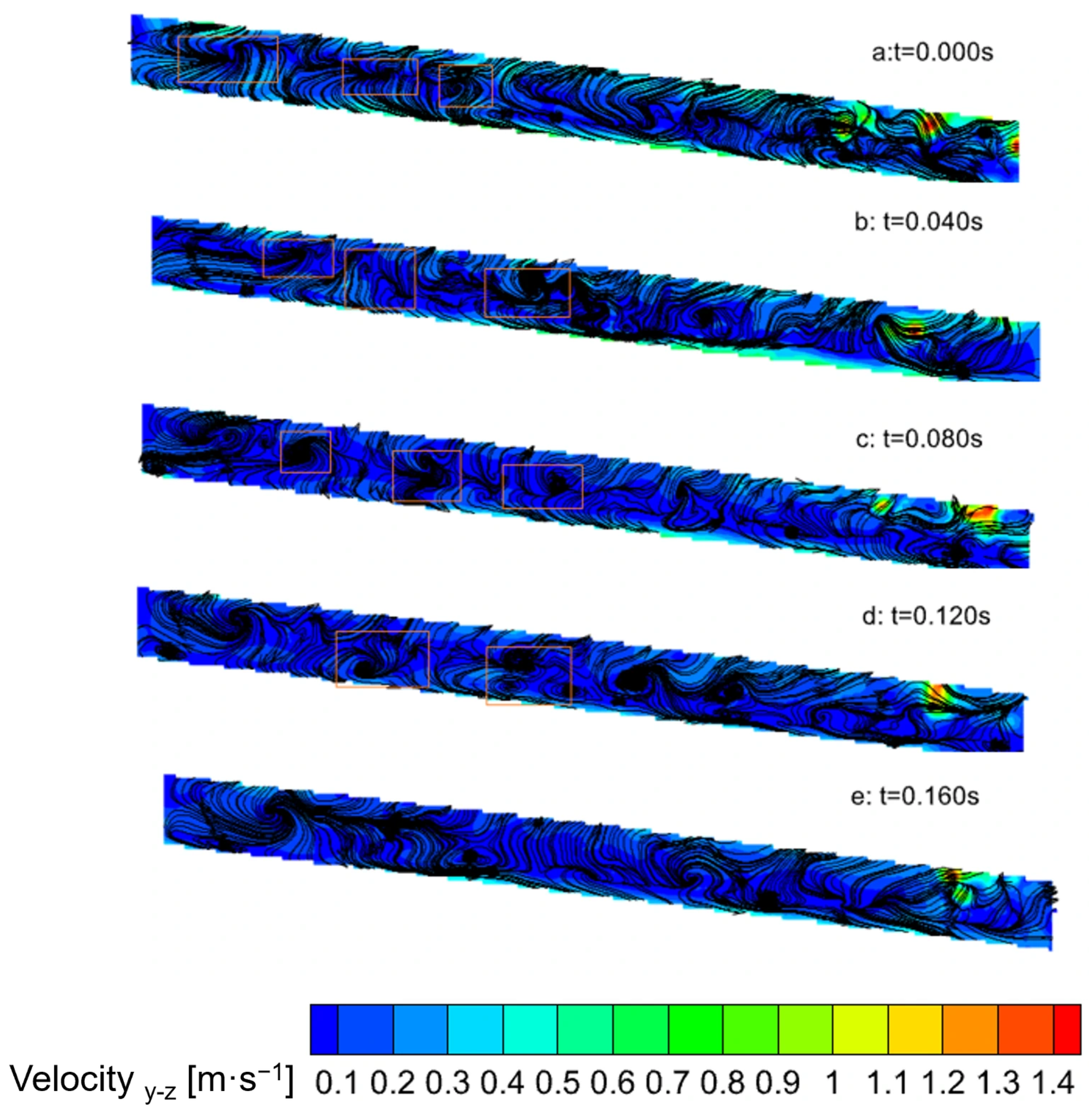
Particle image velocimetry (PIV) was used to record the streamline distributions of the instantaneous velocity field in the upper half of the measurement region over a continuous period of 0.160 s at a flow rate of 6 m
3·h
−1, as shown in
Figure 2.
The boxed regions highlight representative vortical structures and their temporal evolution. Vortices with different characteristic scales were observed throughout the measurement period, while their positions, shapes, and spatial extents continuously changed with time. The flow field therefore exhibited a highly dynamic process involving vortex generation, migration, stretching, merging, and dissipation. At the initial time, several adjacent vortical structures had already developed within the reactor, accompanied by strongly curved streamlines and pronounced entrainment. This behavior indicates strong coupling between the primary swirling motion and axial transport. As the flow evolved, individual vortices migrated downstream and underwent continuous stretching and deformation under the combined effects of local velocity gradients and contraction of the flow passage. Strong interactions between neighboring vortices were also observed. Some small-scale vortices merged into larger structures, whereas larger vortices subsequently fragmented under the influence of shear. Such continuous restructuring demonstrates that the swirling flow was not characterized by a stationary vortex pattern but by a dynamically evolving multiscale flow field. The repeated generation, deformation, and breakdown of vortices are particularly relevant to rapid liquid–liquid precipitation. These processes continuously renew the interfaces between the two reactant streams and promote transverse fluid exchange, thereby reducing local concentration gradients and facilitating a more homogeneous supersaturation field. Meanwhile, the shear and entrainment effects within the flow field may also reduce the prolonged residence of particles in localized high-concentration regions, which may suppress excessive particle growth and agglomeration. Thus, the instantaneous PIV results demonstrate that the annular swirling flow configuration generates a dynamically renewing flow environment favorable for rapid reactive precipitation.
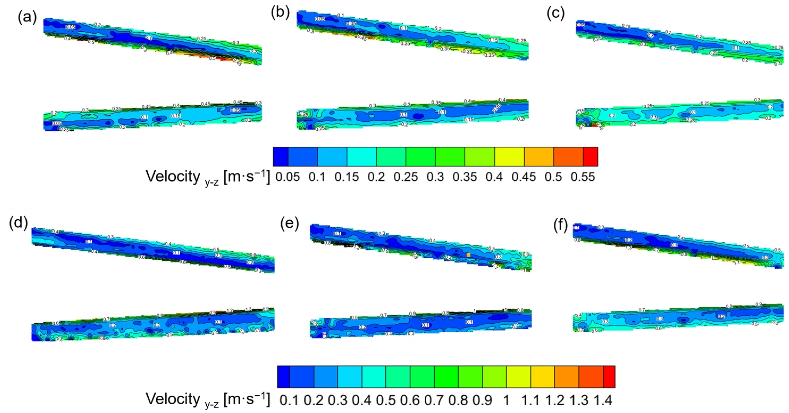
Figure 3 presents the velocity distributions in the axial section (y-z plane) of the swirling flow reactor at different flow rates and relative viscosities.
Because the PIV measurements were performed on the y-z plane, the measured velocity represents the two-dimensional velocity vector within this plane, which is composed of the yand z-direction velocity components. Despite substantial changes in fluid viscosity and flow rate, the overall spatial structure of the velocity field remained similar, and the velocity near the central conical wall was markedly higher than that in the middle of the annular gap. As the viscosity increased, the velocity near the central wall decreased slightly, while the overall distribution pattern remained stable. The effect of flow rate became particularly evident at Q = 6 m3 h−1, where the velocity distributions obtained at different viscosities were similar. This observation indicates that increasing the flow rate increased the inertial contribution sufficiently to compensate, at least partially, for the momentum attenuation associated with viscous dissipation. The velocity was relatively low in the middle of the annular gap between the central conical wall and the outer wall, and regions with velocities approaching zero were even observed. This indicates that the fluid velocity in these regions was directed perpendicular to the y-z plane, corresponding to the circumferential flow around the cone. Consequently, the axially flowing fluid near the central conical wall intersected with the fluid in the middle of the annular gap in a cross flow manner, generating numerous vortices and substantially enhancing the mass transfer process near the conical wall.
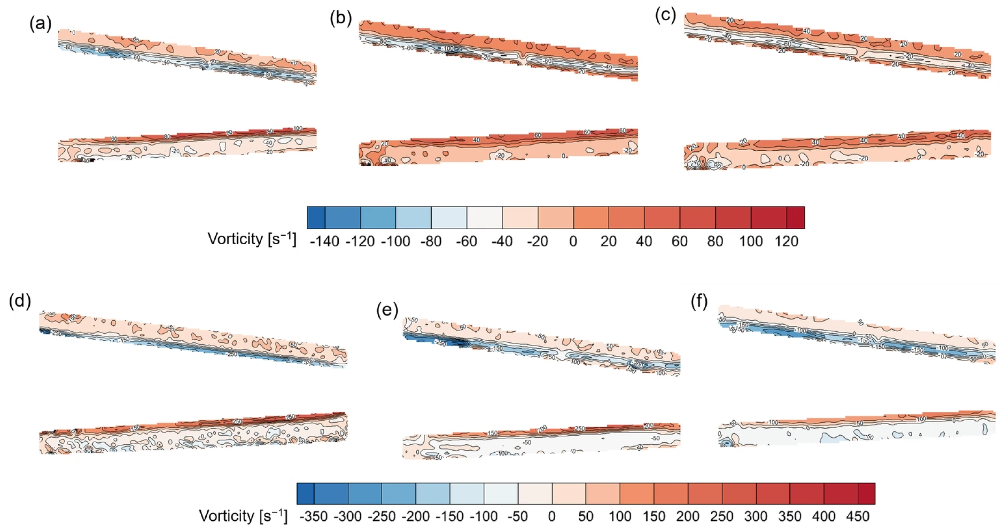
Figure 4 presents the vorticity distributions in the axial section of the swirling flow reactor at different relative viscosities and inlet flow rates.
The high-vorticity regions were concentrated near the central axis, indicating strong velocity shear and momentum exchange in this region, which is important for maintaining the swirling structure and promoting mass transfer. An overall comparison shows that the flow rate was the primary operating parameter governing the vorticity magnitude, whereas the viscosity mainly controlled the degree of decay of the swirling structure. Increasing the inlet flow rate enhanced the velocity gradient near the central axis, thereby increasing the vorticity near the central axis, whereas increasing the viscosity intensified viscous dissipation, causing the high-vorticity regions to gradually weaken and contract. Although viscous suppression became pronounced as the viscosity increased, increasing the flow rate could still effectively mitigate vorticity decay. Therefore, a high flow rate improved the ability of the swirling flow reactor to accommodate thickened systems and provided more favorable flow conditions for interfacial stretching, transverse momentum exchange, and local mixing between the two reactant streams.
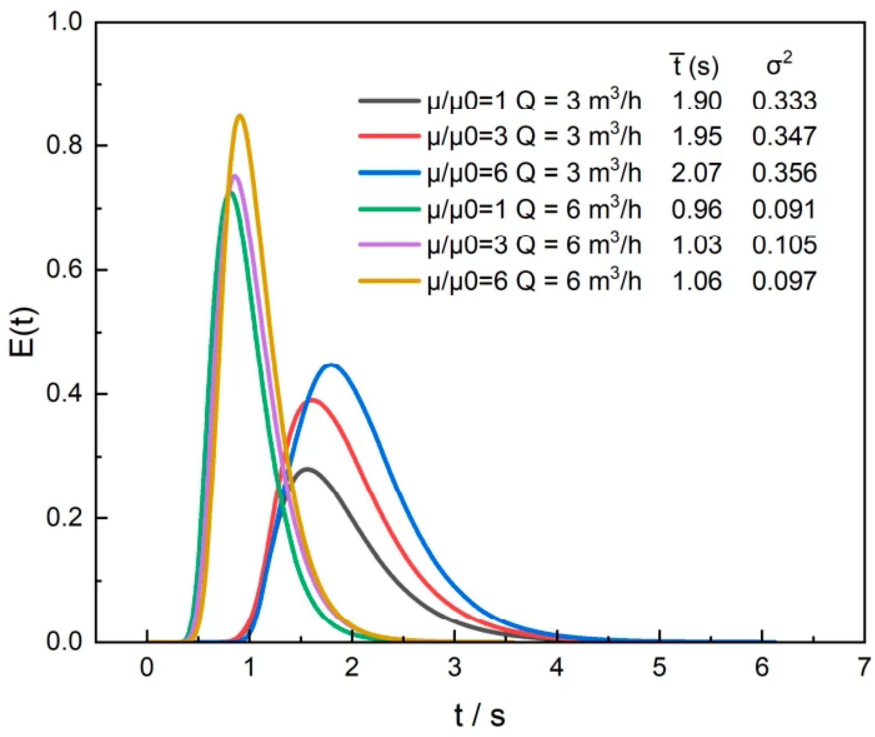
The effects of viscosity and flow rate on the residence time characteristics were further evaluated using CFD-derived residence time distributions (RTDs), as shown in
Figure 5.
The RTD curves under all operating conditions exhibited a single-peak distribution with relatively concentrated peak profiles. No pronounced multiple peaks, premature breakthrough, or prolonged retention were observed, indicating the absence of significant short-circuiting and dead zones within the reactor. Although some curves exhibited a certain degree of tailing, the overall extent of back mixing was low, and the flow behavior was close to plug flow. As the flow rate increased from 3 to 6 m3·h−1, the RTD curves shifted toward shorter residence times, accompanied by a marked reduction in peak width and a shorter tail. These changes indicate that the high flow rate enhanced axial fluid transport and reduced the differences in residence time among individual fluid elements. At Q = 3 m3·h−1, increasing the relative viscosity gradually shifted the curve peak toward longer residence times and broadened the distribution, indicating that the increase in viscosity increased the dispersion of residence times. This may be associated with enhanced viscous dissipation and weakened axial transport. In contrast, at Q = 6 m3·h−1, the RTD curves obtained at different viscosities were relatively similar, with only minor variations in the mean residence time and curve shape. This indicates that a high flow rate reduced the influence of increasing viscosity on the flow distribution, allowing the reactor to maintain relatively stable residence time characteristics in the thickened system.
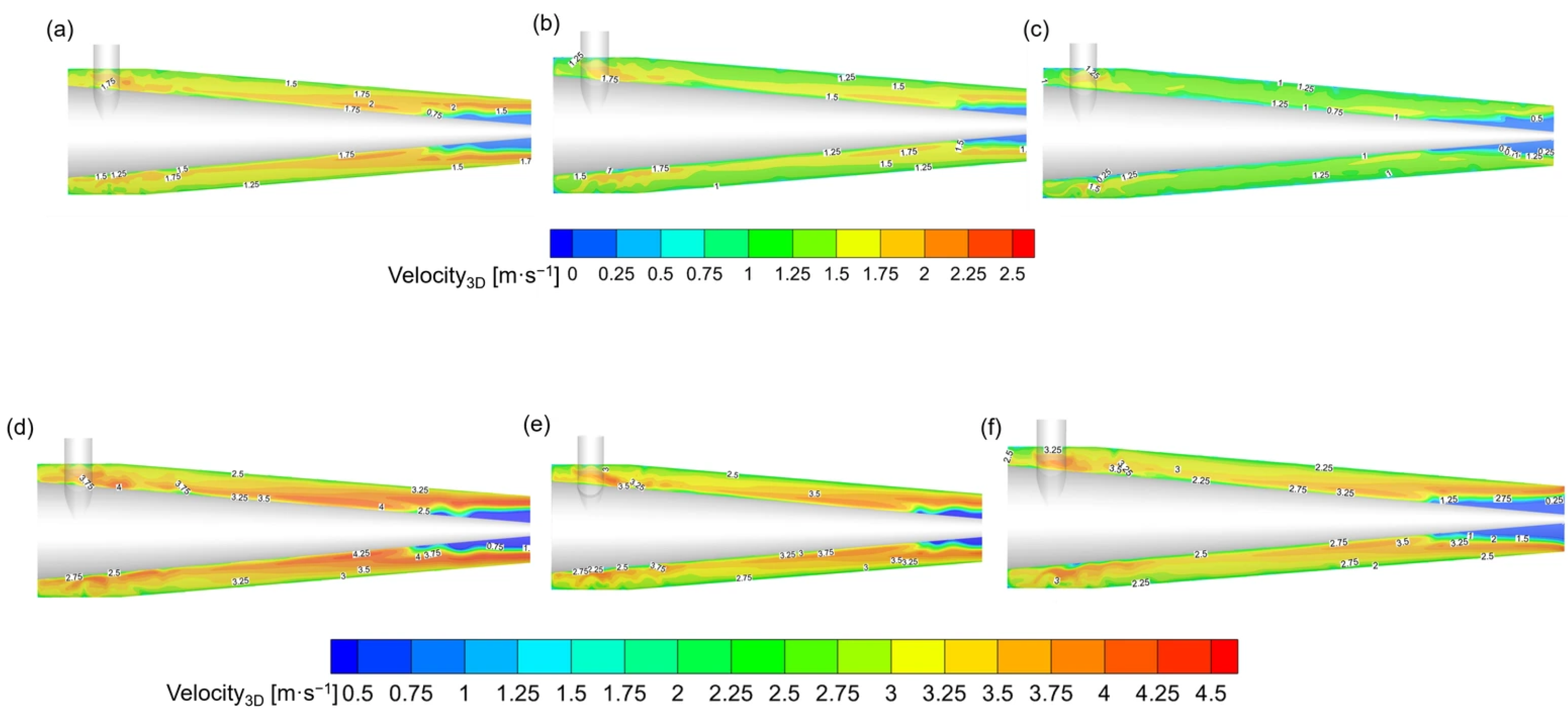
Figure 6 presents the three-dimensional velocity fields obtained from CFD, which include the circumferential velocity component and therefore provide additional insight into the spatial flow structures that cannot be fully resolved by the two-dimensional PIV measurements.
The velocity distributions under different operating conditions exhibited similar spatial characteristics. In the cylindrical inlet region, the two reactant streams converged and redistributed their momentum, resulting in pronounced local velocity variations. After entering the conical section, the fluid accelerated as the flow passage progressively contracted, producing a continuous high-velocity region near the end of the swirling section and toward the outlet. Relatively high velocities and velocity gradients were observed in the inlet convergence region, the near-wall region of the central component, and the vicinity of the outlet, indicating strong momentum exchange at these locations, which favored renewal of the interface between the reactant solutions and local mass transfer.
At the same inlet flow rate, increasing the relative viscosity did not cause any significant change in the flow field structure, consistent with the trend observed in the PIV results. As the viscosity increased, the velocity in the local high-velocity regions decreased slightly, indicating that viscous dissipation accelerated the decay of fluid momentum. This change was more pronounced at Q = 3 m3·h−1. In contrast, at Q = 6 m3·h−1, the velocity distributions under different viscosity conditions remained relatively similar, and continuous high-velocity flow was maintained near the central axis and in the outlet section. Consequently, the reactor retained strong swirling and axial transport capabilities at the high flow rate, demonstrating good adaptability to changes in viscosity.
The dimensionless secondary flow intensity,
Se, was defined as the dimensionless form of the cross-sectionally averaged absolute axial vorticity [
27,
28]:
where
ρ is the fluid density,
dh is the hydraulic diameter,
μ is the dynamic viscosity,
A is the cross-sectional area, and
ωz is the z-direction component of vorticity.
Se is a dimensionless parameter used to characterize the intensity of secondary flow. A larger
Se indicates stronger transverse circulation and secondary flow within the cross-section.
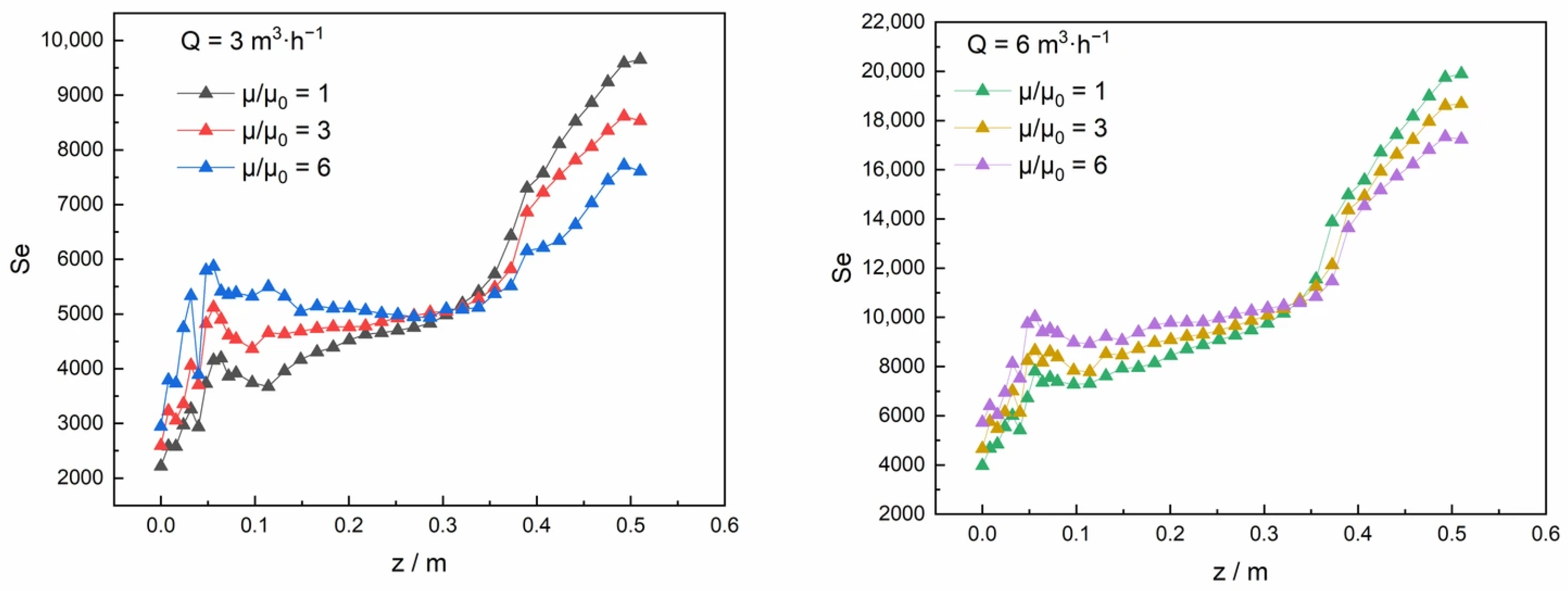
Figure 7 shows the variation in
Se along the axial distance,
z, of the reactor at different inlet flow rates and relative viscosities.
At both flow rates, Se exhibited a characteristic axial evolution, consisting of fluctuations in the inlet region, gradual growth in the middle section, and a pronounced increase toward the outlet. After entering the reactor, the two fluid streams converge, while the swirling structure is still developing; consequently, Se exhibits pronounced fluctuations along the axial direction. In the middle section of the reactor, the inlet disturbances gradually diminish, and a relatively stable balance is established between rotational momentum transport and viscous dissipation. The swirling flow therefore becomes relatively stable, and Se increases almost linearly with axial distance. In the downstream region, the secondary flow intensity increased more rapidly, consistent with the progressive contraction of the flow passage and the resulting acceleration of the fluid.
In the upstream section of the reactor, Se was generally higher under the high-viscosity conditions than under the low-viscosity conditions at the same flow rate. This region primarily corresponds to the convergence of the inlet streams and the initial development of the swirling flow. Increasing the viscosity may enhance the transverse diffusion of tangential momentum across the cross-section, allowing rotational motion to propagate from the local region near the inlet to the surrounding fluid. Meanwhile, the stronger viscous effect may suppress the rapid breakup of small-scale vortical structures, thereby favoring the maintenance of larger and more spatially continuous swirling structures. However, this trend was reversed in the middle and downstream sections. As the flow became increasingly governed by channel contraction and axial acceleration, the lower-viscosity fluid experienced weaker viscous damping and therefore retained greater rotational momentum and stronger cross-sectional circulation. At the same relative viscosity, increasing the inlet flow rate from 3 to 6 m3·h−1 resulted in a substantial increase in Se throughout the axial range, indicating that a high flow rate effectively intensified the swirling motion and transverse transport within the reactor cross-section. At the relatively high inlet flow rate, the fluid retained more rotational momentum and developed a higher tangential velocity and a greater increase in axial vorticity as the radius of rotation decreased, leading to a rapid increase in Se. In contrast, under the low flow rate conditions, the fluid inertia was weaker, and the rotational momentum was more susceptible to wall shear and internal viscous dissipation. Consequently, both the axial development of the secondary flow and its downstream intensification were relatively limited.
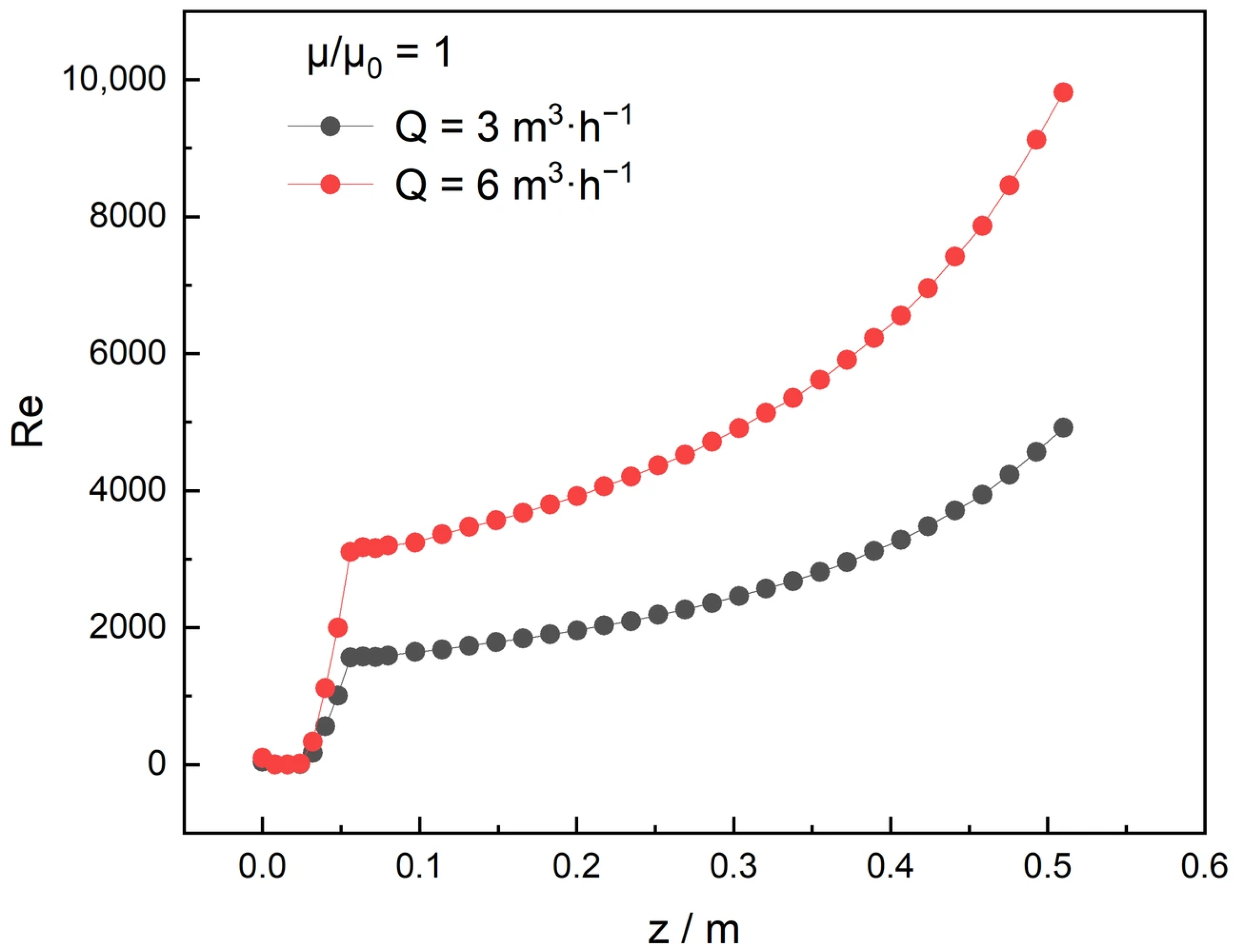
Figure 8 presents the axial distribution of the dimensionless Reynolds number at different inlet flow rates for (μ/μ
0 = 1). Considering the variable annular geometry of the swirling flow reactor, the hydraulic diameter and flow characteristics vary along the axial direction. Therefore, a local Reynolds number was employed to characterize the flow conditions at different axial positions and was defined as:
where
ρ is the fluid density,
μ is the dynamic viscosity,
dh is the local hydraulic diameter, and
is the area-weighted average axial velocity at the corresponding axial position.
As shown in
Figure 8, after the inlet region, the local Reynolds number generally increased along the axial direction. This variation is associated with the changing annular geometry and the corresponding evolution of the axial velocity. Increasing the inlet flow rate from 3 to 6 m
3·h
−1 resulted in substantially higher Reynolds numbers, indicating a greater relative contribution of inertial effects compared with viscous effects at the higher flow rate. For a given flow rate and reactor geometry, increasing the fluid viscosity decreases the Reynolds number. Since the Reynolds-number profiles at higher relative viscosities exhibit a similar axial trend with lower magnitudes, only the results at μ/μ
0 = 1 are presented in
Figure 8 for clarity.
3.2. Preparation Results of Calcium Carbonate Particles
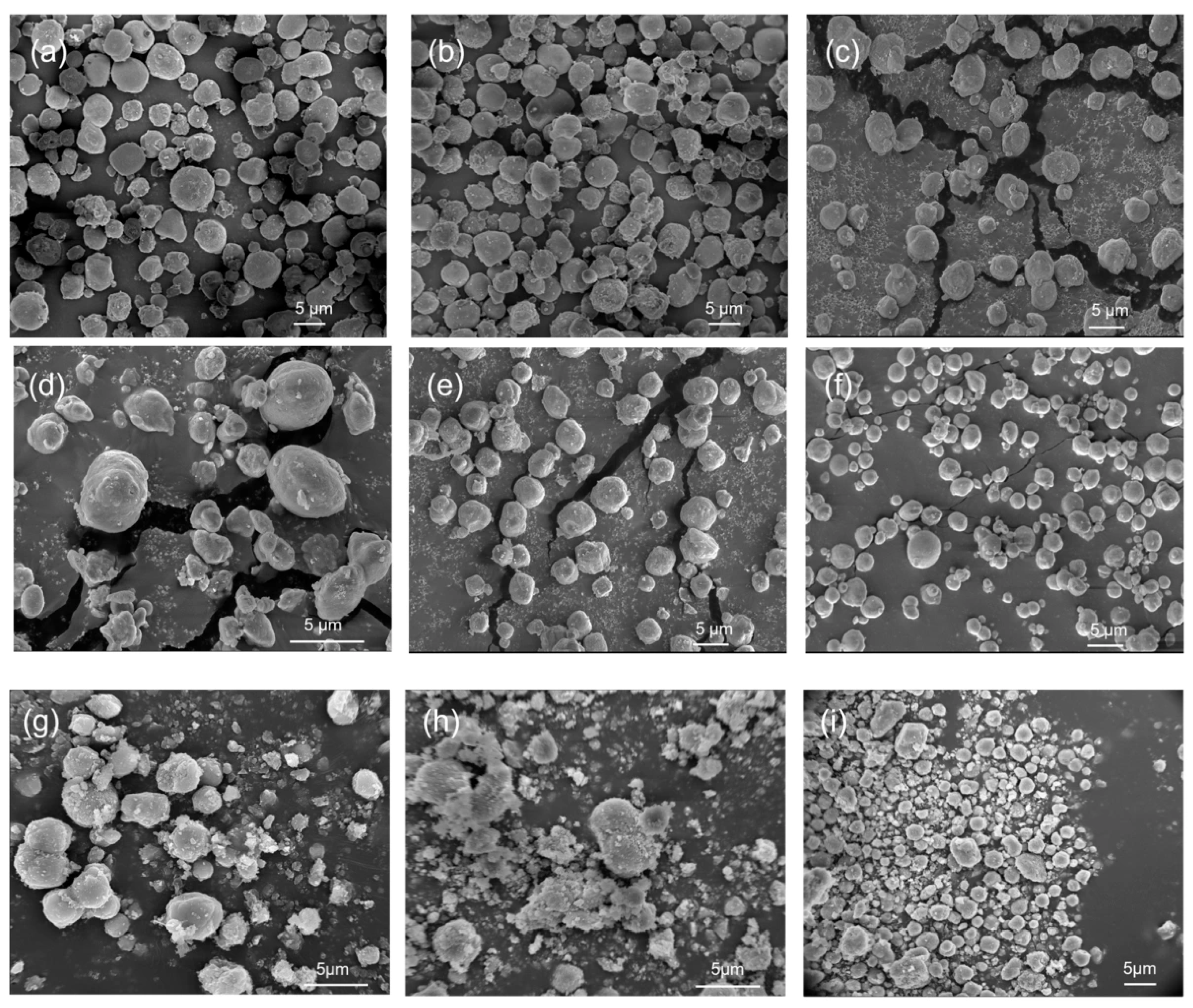
Figure 9 presents SEM images of CaCO
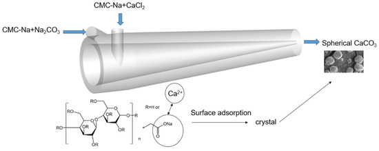
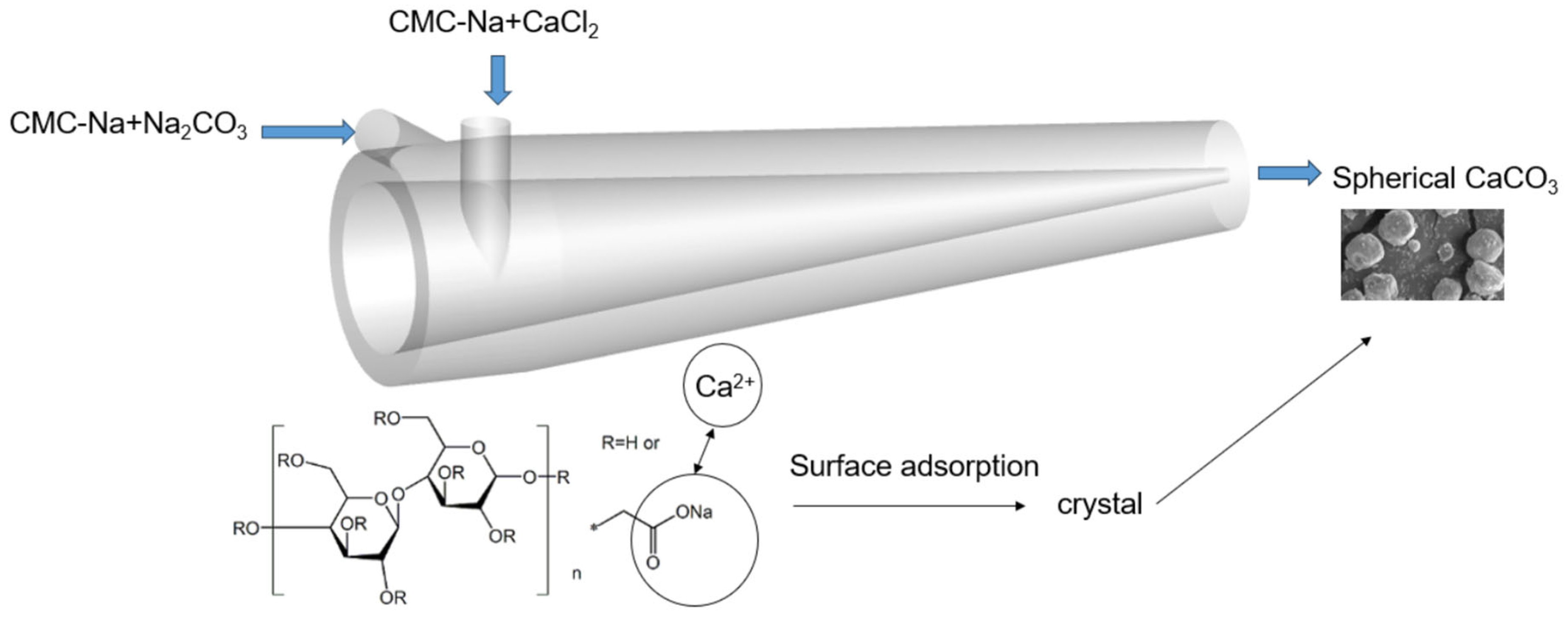
3 particles prepared under different operating conditions. In this precipitation system, CMC-Na may interact with Ca
2+ through its carboxylate groups and associate with the CaCO
3 crystal surface, thereby regulating crystal growth and particle aggregation and favoring the formation of spherical particles.
When only the Na
2CO
3 solution was thickened, the particles prepared at Q = 3 m
3·h
−1 and Q = 6 m
3·h
−1 were predominantly spherical. As the flow rate increased from 3 to 6 m
3·h
−1, the number of large irregular particles and localized aggregates decreased, while the particle sphericity and size uniformity improved slightly. This observation is consistent with the particle size distribution results in
Figure 10 and the quantitative parameters in
Table 1. The Span values remained relatively low under these conditions, indicating that the particles produced in the swirling flow reactor maintained relatively narrow size distributions. The increase in flow rate enhanced the mixing performance and mass transfer capability of the swirling flow reactor. When both the Na
2CO
3 and CaCl
2 solutions were thickened, the effect of flow rate on particle morphology became more pronounced. When the relative viscosities of both solutions were 3, increasing the flow rate resulted in a more regular particle morphology. When the relative viscosities of both solutions were further increased to 6, rough spherical particles with considerable size differences were formed at Q = 3 m
3·h
−1, together with smaller particles and irregular aggregates, indicating that the increase in viscosity weakened the mixing and mass transfer processes at this flow rate. In contrast, the particles obtained at Q = 6 m
3·h
−1 were smaller, more spherical, and smoother, with markedly reduced size differences among the particles. The corresponding particle size distributions in
Figure 10 also remained relatively concentrated, as the flow rate increased from 3 to 6 m
3·h
−1, consistent with the improved particle size uniformity observed in the SEM images. This improvement can be directly related to the hydrodynamic results discussed above. The inertial effects, swirling intensity, and secondary flow generated at the high flow rate effectively compensated for the viscous dissipation caused by the increase in viscosity, thereby potentially reducing local variations in supersaturation. Meanwhile, the lower mean residence time and variance at the high flow rate reduced differences in the residence histories of fluid elements, which may have contributed to the more uniform particle sizes.
At the same viscosity, particles produced in the stirred system exhibited more pronounced agglomeration and greater size heterogeneity than those obtained in the swirling flow reactor. In particular, at μ/μ0 = 3 and N = 400 rpm, numerous fine particles coexisted with loosely packed aggregates. When the stirring speed was increased to 1800 rpm, the number of large aggregates decreased, and the number of discrete spherical particles increased; however, the coexistence of fine particles and larger particles remained evident. This morphological observation is consistent with the quantitative particle size results. The particles prepared in the swirling flow reactor exhibited relatively narrow and concentrated size distributions, whereas those obtained in the stirred system showed broader and more variable distributions. In particular, the larger D90 values observed under some stirred conditions indicate a more pronounced coarse-particle tail, consistent with the large aggregates observed in the SEM images. This suggests that increasing the conventional stirring speed may have been insufficient to eliminate local mixing heterogeneity within the stirred apparatus.
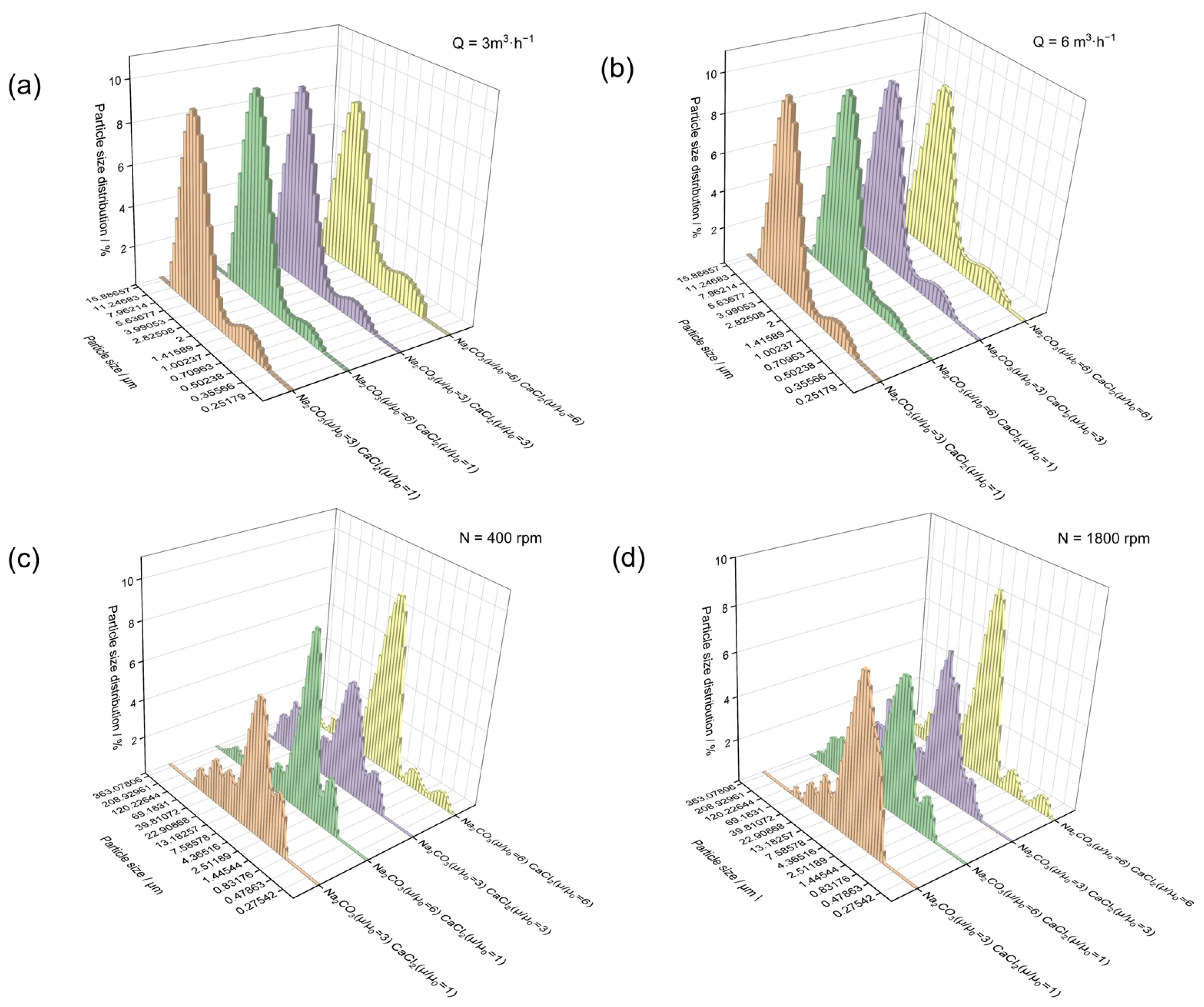
Figure 10 presents the particle size distributions of CaCO
3 particles prepared under different operating conditions, while the corresponding D
10, D
50, D
90, and Span values are summarized in
Table 1.
Under all conditions, the particles prepared in the annular swirling flow reactor exhibited relatively concentrated particle size distributions dominated by a single peak. Only slight shoulder peaks in the small-particle-size region or tailing were observed under some thickened conditions. As shown in
Table 1, the particles prepared in the swirling flow reactor exhibited Span values ranging from 1.207 to 1.611, indicating relatively narrow particle size distributions under the investigated conditions. As the flow rate increased, the position of the main peak changed only slightly, whereas the overall distribution became narrower. Increasing the flow rate therefore mainly improved particle size uniformity. This result can be attributed to the enhanced fluid inertia, swirling intensity, and secondary flow at high flow rates, which promoted rapid and uniform mixing of the reactants and reduced fluctuations in local supersaturation.
In contrast, the particle size distributions obtained in the stirred system were markedly broader than those obtained in the swirling flow system, with multiple peaks and pronounced coarse-particle tailing. The D90 values of the stirred samples were substantially higher and showed greater variation than those obtained in the swirling flow reactor. Correspondingly, the Span values were also higher and more variable, indicating broader particle size distributions. When the stirring speed was increased from 400 to 1800 rpm, the coarse-particle fraction decreased under some viscosity conditions; however, the particle size distributions remained broad and multimodal. Increasing the stirring speed improved macroscopic dispersion; however, the particle size distributions remained relatively broad. Overall, the combined SEM and particle size results indicate that the annular swirling flow reactor was more effective in maintaining particle size uniformity and limiting the formation of large aggregates under the investigated conditions.
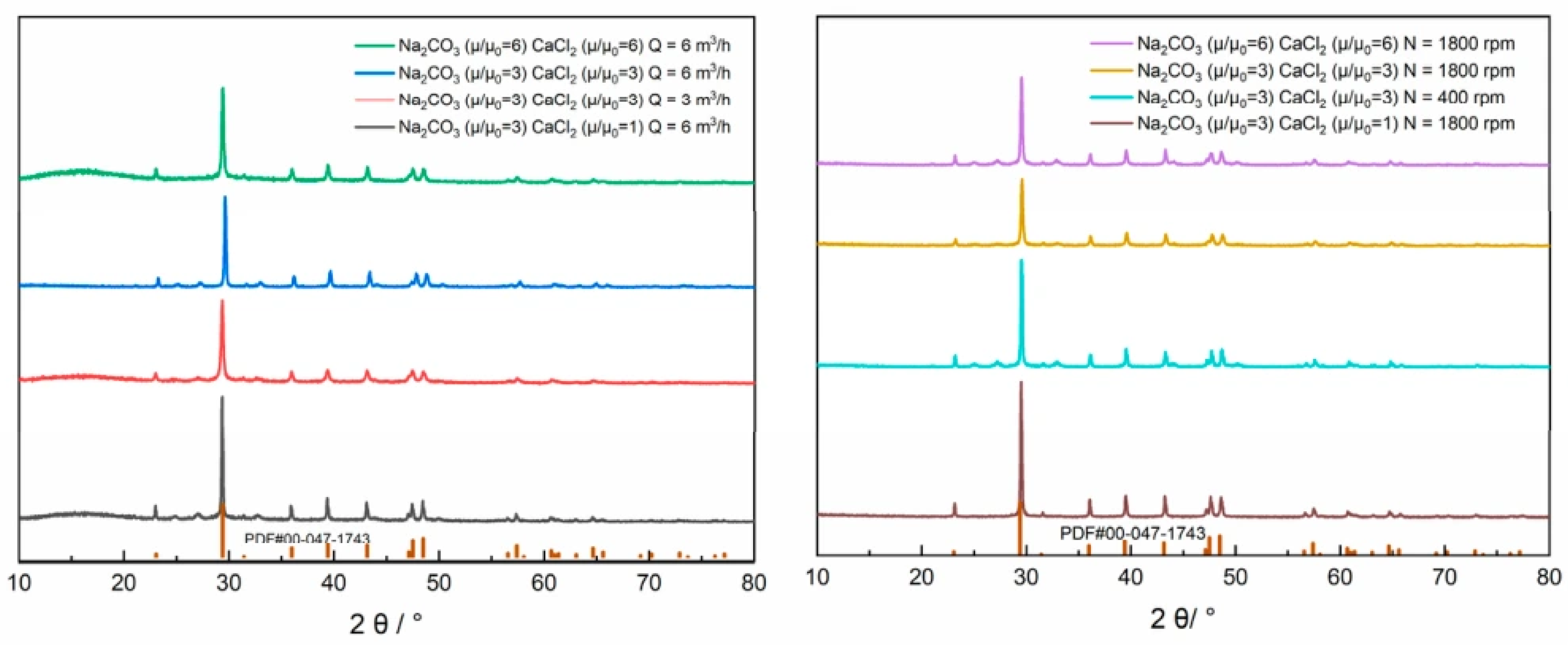
Figure 11 presents the XRD patterns of the CaCO
3 particles obtained under different feed viscosities and hydrodynamic conditions.
The characteristic diffraction peaks of the samples were assigned to the (012), (104), (110), (113), (202), and (018) crystal planes of calcite CaCO
3, consistent with the results reported in the literature [
13]. Among these peaks, the (104) reflection located at approximately 29.4° exhibited the highest intensity, indicating that calcite was the predominant crystalline phase of the products obtained under all conditions. Therefore, the CaCO
3 particles prepared at different feed viscosities and using different preparation methods (swirling flow and stirring) all existed in the calcite form.