Technical Note

Research on Grinding Wheel Dressing and Tooth Flank Topology Control for Generating Grinding of Internal Helical Gears


School of Mechatronics Engineering, Henan University of Science and Technology, Luoyang 471003, China
*
Author to whom correspondence should be addressed.
Processes 2026, 14(18), 2947; https://doi.org/10.3390/pr14182947
Submission received: 25 July 2026 / Revised: 6 September 2026 / Accepted: 13 September 2026 / Published: 16 September 2026
(This article belongs to the Section Manufacturing Processes and Systems)

Abstract

Internal helical gears offer advantages such as high transmission accuracy and smooth operation, making them widely used in transmission systems such as electric vehicle reducers and wind turbine gearboxes. Based on the conjugate surface enveloping theory and the spatial meshing principle, this manuscript performs the modification calculation of the spherical worm grinding wheel profile and the tooth flank topology of the internal helical gear. Numerical examples are introduced to calculate the discrete points of the modified tooth surfaces of the spherical worm grinding wheel and the internal helical gear, as well as to construct the corresponding models. The dressing motion control for the spherical worm grinding wheel profile and the internal helical gear tooth flank topology is realized. By investigating the implementation methods of the spherical worm grinding wheel dressing and the generating grinding process for internal helical gears, a feasible technical solution for efficient generating grinding is developed, providing a theoretical foundation for the large-scale application of internal helical gears.

1. Introduction

Planetary gear reducers and star reducers feature compact structure, large reduction ratio and high transmission efficiency, exhibiting outstanding performance advantages in transmission systems such as wind turbine gearboxes, main drives for shield machine cutterheads, and reducers for electric commercial vehicles. As a core component of planetary gear reducers, the internal helical ring gear critically influences the operational performance of the planetary reducers. Therefore, conducting research on its precision machining technology is of great engineering significance [1,2].
Currently, the hard tooth surface finishing of internal helical gears mainly includes power skiving, gear honing and form grinding [3]. Jia [4] proposed a general calculation method for cutting edge profile curves for skiving of non-specific internal and external profiles, and completed the solution of cutting contact points and skiving motion simulation. Hong [5,6] designed the helical skiving cutter, completed relevant cutting-edge calculations, and analyzed the factors affecting skiving machining accuracy. Yoshikoto [7] realized a large shaft crossing angle between the internal gear and the grinding wheel using a gear-shaped grinding wheel, completed the numerical analysis of the grinding wheel profile, and conducted grinding experiments. Han [8] proposed a tooth surface topological modification method for worm wheel grinding based on a flexible electronic gearbox and realized modification accuracy control. Wang [9] established a regression model between grinding parameters and tooth surface roughness using a two-stage stepwise regression method, constructed a multi-objective optimization model with machining efficiency and tooth surface roughness as objectives, and optimized the grinding parameters using the particle swarm optimization algorithm. Wang [10] proposed a high-precision method for constructing lead-modified tooth surfaces. Based on the principle of lead modification, the actual contact line equation of form-ground gears was derived; by varying the center distance, multiple sets of contact lines were obtained along the tooth lead direction, and the lead-modified tooth surface was obtained through NURBS surface fitting; the main factors affecting tooth surface accuracy, namely profile deviation and helix deviation, were analyzed and an error evaluation model was proposed. Xia [11] proposed a method to realize gear modification machining by adjusting the motion parameters of each axis of the internal gear power honing machine tool, and completed the optimization of machine tool motion parameters. Han [12] proposed a modification method based on electronic gearbox control for power honing of internal helical gears to realize tooth surface lead and profile modification. Denkena [13] investigated the geometric shape of the gear grinding contact zone through numerical simulation technology. Su [14] studied the grinding wheel dressing method for internal gear form grinding, derived the coordinate calculation formulas for the grinding wheel profile and dressing trajectory in internal gear form grinding, and investigated the response characteristics of stress and displacement of the grinding wheel head to frequency. Guo [15] studied the method of grinding face gears on a six-axis CNC worm wheel grinding machine, and proposed a method for dressing face gear worm wheels using a standard conical diamond roller, which improved the versatility of diamond rollers. Ren [16] studied the tooth surface modification method and form grinding technology of internal helical gears, and the experimental results show that the form grinding accuracy can reach grade 4.
Nevertheless, power skiving suffers from inherent tooth surface errors originating from its machining principle, resulting in uncontrollable tooth surface topography and insufficient profile accuracy inferior to that of gear grinding. Gear honing possesses limited correction capacity for profile deviation. The single-tooth indexing grinding characteristic of the form grinding method drastically reduces grinding efficiency, which fails to cope with the supply shortage of internal helical gears in the new energy vehicle market. Therefore, an efficient machining technology for internal helical gears is urgently required to meet industrial demands.
Li [17] proposed a machining method for worm wheel grinding with stroke variable speed varying in accordance with a sine function. Zhao [18] investigated the principle of the two-parameter planar dressing method for worm grinding wheels used in face gear grinding. Li [19] established an error tooth surface model of the double-side grinding method via numerical calculation. Liao [20] proposed on-machine dressing of wheel tooth profiles using an annular diamond roller, which compensates for three-dimensional surface errors of the grinding wheel by modifying the two-dimensional tooth profile. Wang [21] studied the wear law of diamond rollers, which contributes to improving dressing accuracy in precision grinding. Ran [22] researched the modeling of crowned worm grinding wheels for face gear grinding and put forward a dressing method for crowned worm grinding wheels for face gears on standard worm wheel grinding machines.
In summary, although many valuable achievements have been made in the manufacturing technology and dressing methods of worm grinding wheels for face gear grinding, the modeling and dressing of spherical worm grinding wheels for generating grinding of internal helical gears still remain at the theoretical stage and cannot meet the development needs of China’s electric commercial vehicle industry. This manuscript investigates the technology of generating grinding of internal helical gears with spherical worm grinding wheels. By introducing the concept of equivalent helical gear topological modification, the mathematical models of the modified internal helical gear and the spherical worm grinding wheel are established based on the conjugate surface envelope theory and the spatial meshing principle. The profile dressing motion of the spherical worm grinding wheel and the motion law of each axis during generating grinding of internal helical gears are analyzed. The mathematical model of the spherical worm grinding wheel dressed by a diamond roller is constructed, and the axis motion parameters during generating grinding are derived. Finally, indirect verification of the theories of spherical worm grinding wheel dressing and internal helical gear generating grinding is realized.

2. Machining Principle of Generating Grinding Internal Helical Gears with Spherical Worm Grinding Wheels

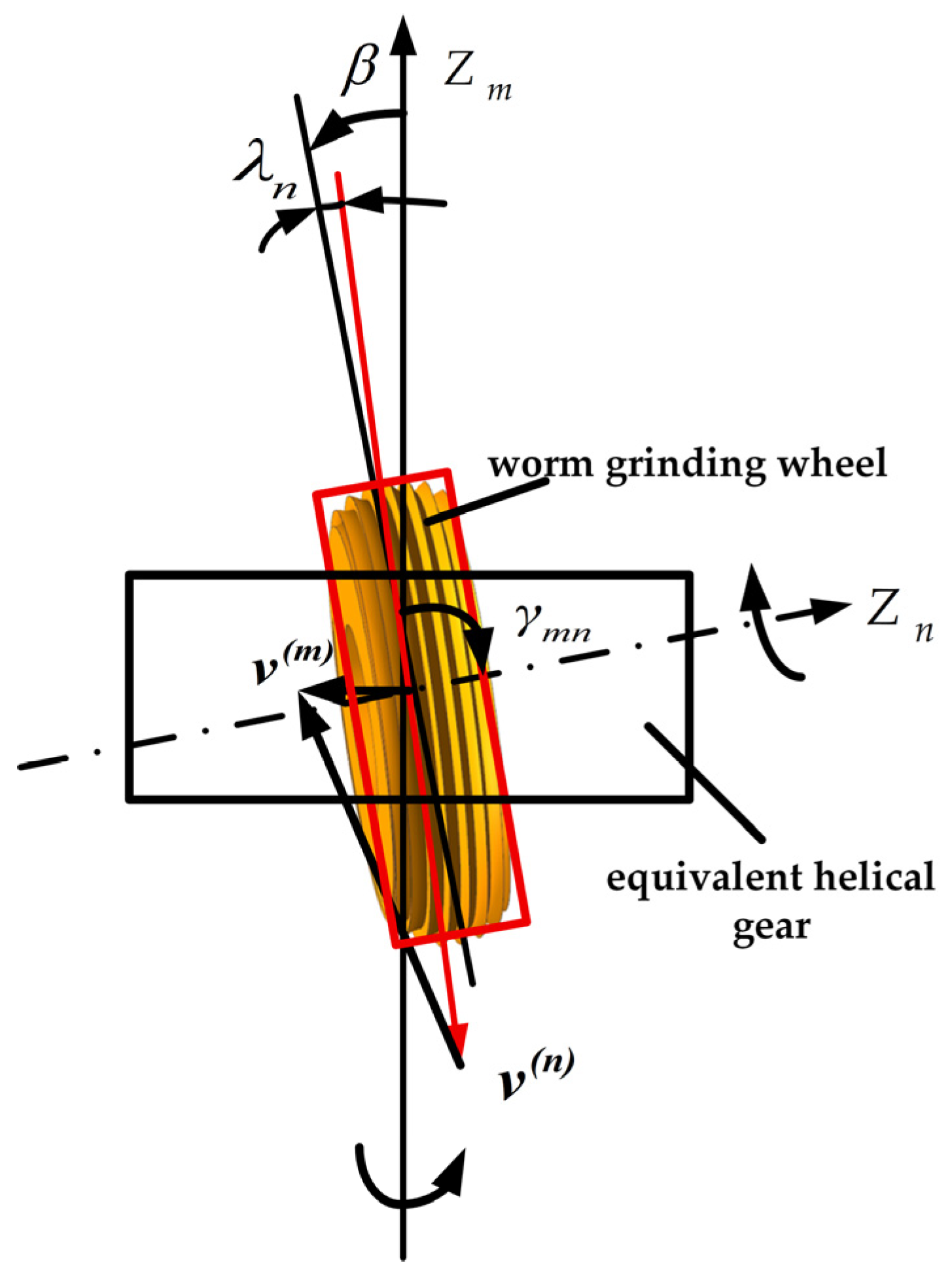
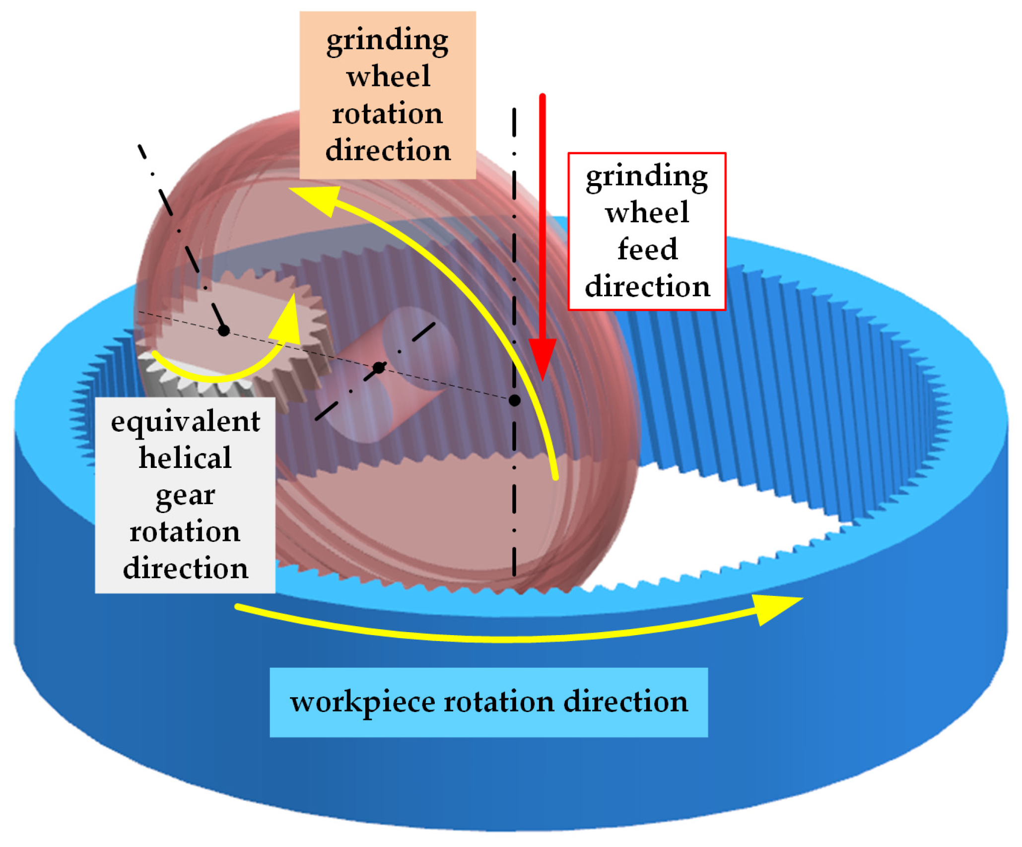
During the generating grinding process of internal helical gears using a spherical worm grinding wheel, the kinematic relationship can be equivalent to the meshing transmission between a helical gear and an internal helical gear. The positional relationship among the three components is shown in Figure 1.
The formation mechanism of the spherical worm grinding wheel is similar to the evolution of a rack-type generating gear hob. At any instant, the axial profile of the grinding wheel coincides with the normal profile of an equivalent helical gear. The normal tooth profile involute of the helical gear, taking the spherical helix as its motion trajectory, rotates around the grinding wheel axis to form the spherical worm grinding wheel. The helix angle of the equivalent helical gear formed by the axial section of the grinding wheel is not equal to that of the workpiece in magnitude, which is equivalent to a pair of crossed-axis helical gear pairs. Therefore, the helical gear axis, the grinding wheel axis and the workpiece axis are all in a spatial crossed relationship.

3. Calculation of Modified Tooth Surfaces for Spherical Worm Grinding Wheel and Internal Helical Gear

3.1. Topological Modification of Equivalent Helical Gears

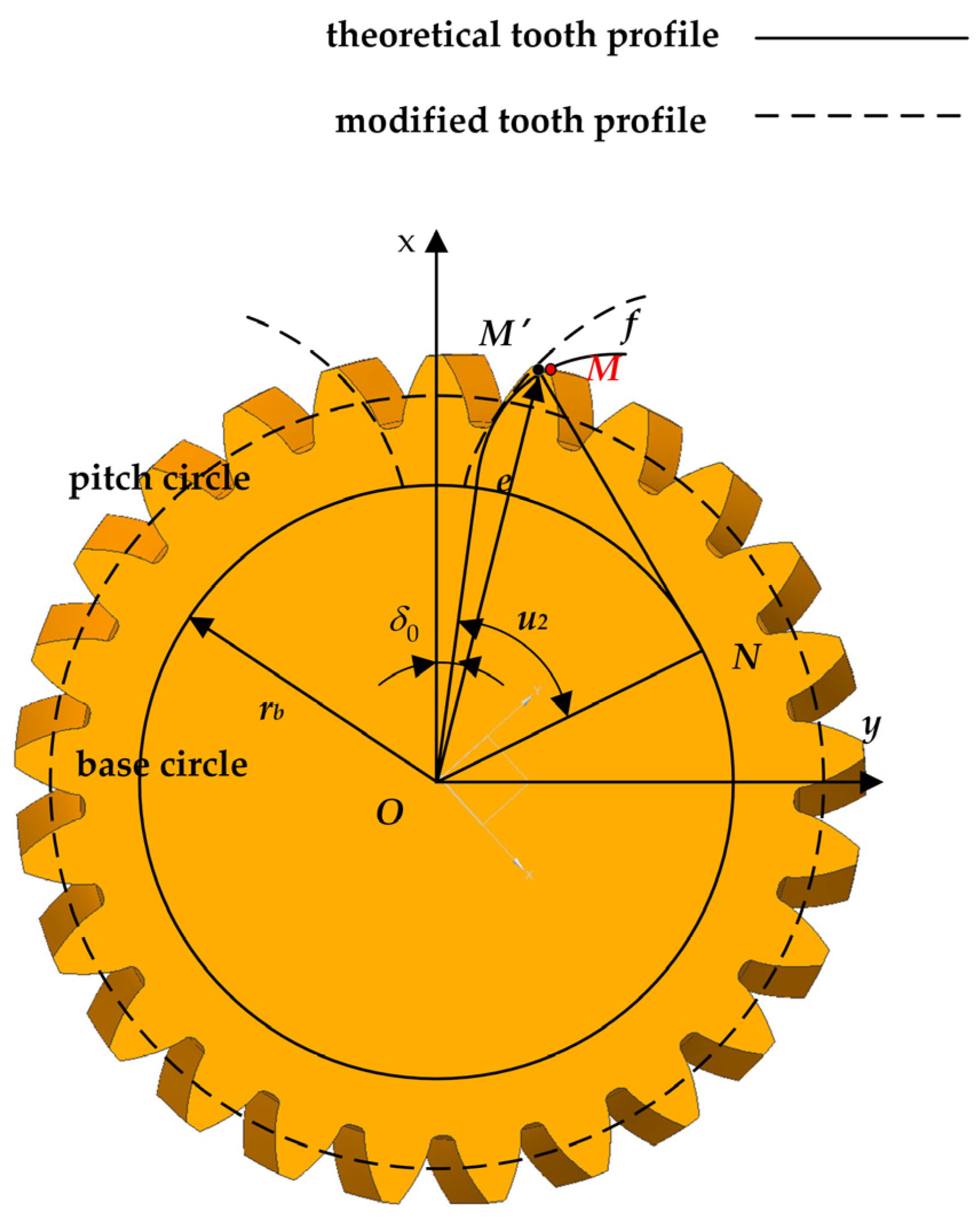
A schematic diagram illustrating the transverse profile variations in the equivalent helical gear before and after tooth profile modification is constructed, as shown in Figure 2. In the figure, the tooth space is symmetrical about the axis x , the radius of the base circle is r b , the starting point of the theoretical involute profile e f on the right side is e , and the included angle between O e and the x axis is δ 0 . Let M be an arbitrary point on the involute tooth profile e f ; its normal line M N is tangent to the base circle at point N . Take e O N = u 2 as the parameter, where M N = r b u 2 . Point M is the corresponding point on the modified tooth profile matching point M on the theoretical profile, and M N denotes the modification amount superimposed on the generating line at point M of the involute tooth profile.
Let M M = Δ L , whose expression is given as follows:
Δ L = a 1 ( L L 0 ) 2 + b 1 ( L L 0 ) 1 + c 1
where a 1 , b 1 , c 1 are modification coefficients; L represents the generating line length at point M , and L 0 denotes the generating line length at the point where the modification amount is zero.
The modified tooth profile can be obtained by superimposing the modification amount Δ L onto the theoretical tooth profile, and the specific equation is given as follows:
r k = x 2 y 2 z 2 = r b cos ( δ 0 + u 2 + θ 2 ) + ( r b u 2 + Δ L ) sin ( δ 0 + u 2 + θ 2 ) r b sin ( δ 0 + u 2 + θ 2 ) ( r b u 2 + Δ L ) cos ( δ 0 + u 2 + θ 2 ) P 2 θ 2
where θ 2 is the rotation angle of point M around the axis z ; P 2 = ± P z / ( 2 π ) , where P 2 is the helical parameter of the helical gear (the positive sign is adopted for right-hand helical gears and the negative sign for left-hand helical gears) and P z denotes the lead of the helix.
The tooth lead is designed with a second-order parabolic function, and the modification amount Δ E can be expressed as follows:
Δ E = a ( P 2 θ 2 b 2 ) 2 + c ( P 2 θ 2 b 2 ) + d
where a , c , d is the coefficient of the second-order modification function and b stands for the tooth width of the helical gear.
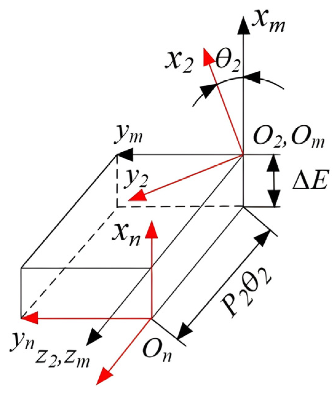
During the tooth lead modification of the equivalent helical gear, the coordinate systems for the grinding process are illustrated in Figure 3. S 2 is the coordinate system rigidly attached to the equivalent helical gear, S n is the coordinate system rigidly attached to the spherical worm grinding wheel, and S m is the coordinate system rigidly attached to the worktable.
The spherical worm grinding wheel simultaneously moves along the axial direction of the helical gear by a displacement of l n = P 2 θ 2 , and it moves radially relative to the helical gear by a displacement of Δ E .
The tooth surface equation after tooth lead modification is given as follows:
r t = r b cos ( δ 0 + u 2 + θ 2 ) + r b u 2 sin ( δ 0 + u 2 + θ 2 ) Δ E cos θ 2 r b sin ( δ 0 + u 2 + θ 2 ) r b u 2 cos ( δ 0 + u 2 + θ 2 ) + Δ E sin θ 2 P 2 θ 2
Simultaneous profile and tooth lead modification of the equivalent helical gear yields the topologically modified tooth surface expressed as follows:
r t = r b cos ( δ 0 + u 2 + θ 2 ) + ( r b u 2 + Δ L ) sin ( δ 0 + u 2 + θ 2 ) Δ E cos θ 2 r b sin ( δ 0 + u 2 + θ 2 ) ( r b u 2 + Δ L ) cos ( δ 0 + u 2 + θ 2 ) + Δ E sin θ 2 P 2 θ 2

3.2. Solution of Modified Profile for Spherical Worm Grinding Wheel

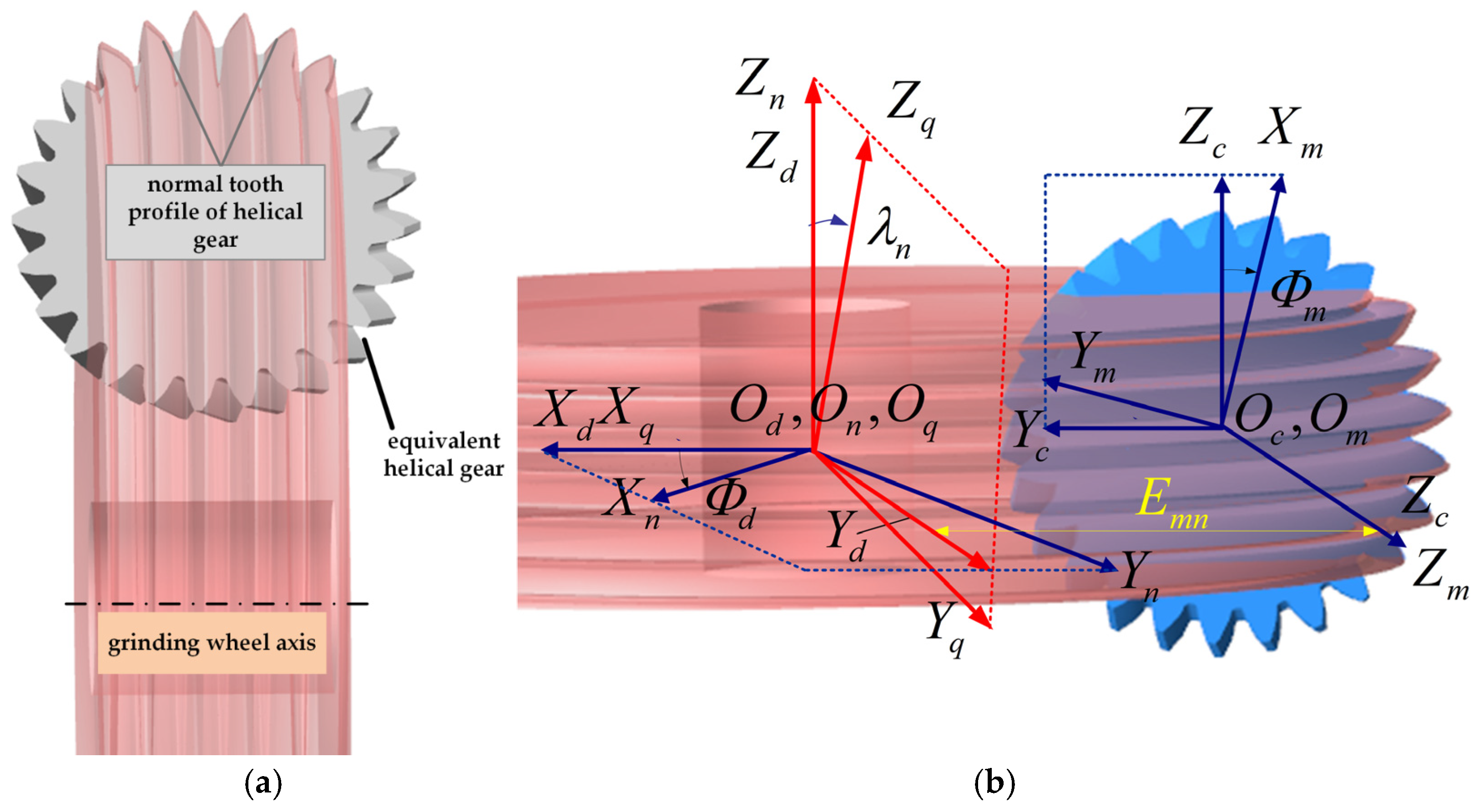
The profile of the spherical worm grinding wheel is constructed based on the conjugate surface envelope theory, and the analytical calculation of the wheel surface of the worm grinding wheel is carried out by solving the meshing equations. The formation principle of the spherical worm grinding wheel is shown in Figure 4a. Based on the aforementioned formation mechanism of the spherical worm grinding wheel profile, the coordinate system of the equivalent helical gear to spherical worm grinding wheel is established as shown in Figure 4b. In the figure, the fixed coordinate system of the equivalent helical gear is O c - X c Y c Z c and the moving coordinate system of the equivalent helical gear is O m - X m Y m Z m . The equivalent helical gear rotates about its axis, O m Z m , at a rotational speed of ω m with a rotation angle of Φ m . The fixed coordinate system of the spherical worm grinding wheel is O d - X d Y d Z d , the moving coordinate system of the spherical worm grinding wheel is O n - X n Y n Z n , and O q - X q Y q Z q denotes the auxiliary coordinate system. E m n represents the shortest distance between the axes of the equivalent helical gear and the spherical worm grinding wheel; r p n   = E m n   + r p m is the radius of the worm grinding wheel, r p m is the radius of the equivalent helical gear, λ n is the helix lead angle of the spherical worm grinding wheel, and γ m n is the intersection angle between the cross-section of the equivalent helical gear and the axis of the worm grinding wheel. The worm grinding wheel rotates about its axis, O d Z d , at a rotational speed of ω d with a rotation angle of Φ d .
The relationship of Φ m and Φ d is expressed as follows:
Φ d = m d m Φ m = N m N d Φ m
where m d m stands for the transmission ratio between the gear and the grinding wheel, N m is the number of starts of the grinding wheel, and N d represents the number of teeth of the helical gear.
The included angle between the axes of the spherical worm grinding wheel and the equivalent helical gear, as well as their rotational relationship, are shown in Figure 5.
In the figure, the equivalent helical gear is right-handed and the spherical worm grinding wheel is right-handed, and their velocity directions at the meshing point P are identical. The included angle between the axes of the equivalent helical gear and the spherical worm grinding wheel satisfies the following relation:
γ m n = 90 β + λ n
where β denotes the helix angle of the equivalent helical gear.
The worm grinding wheel contacts the equivalent helical gear at meshing point P. The meshing condition at this point is given below:
N ( m ) v ( m n ) = 0 v ( m n ) = v ( m ) v ( n )
where N ( m ) is the normal vector of a point on the tooth flank of the equivalent helical gear; v ( m n ) denotes the relative velocity between the meshing point on the tooth flank of the equivalent helical gear and the meshing point on the tooth flank of the worm grinding wheel; v ( m ) is the velocity of the meshing point on the tooth flank of the equivalent helical gear, and v ( n ) is the velocity of the meshing point on the tooth flank of the worm grinding wheel.
The coordinate vector of point P in the coordinate system O c - X c Y c Z c is expressed as r ( c ) ( P ) = r p m 0 0 T . Let the number of starts of the worm grinding wheel be N n , then
N n Φ n = N m Φ m ,   ω m ω n = N n N m
The velocities of the meshing point on the tooth flank of the equivalent helical gear and on the tooth flank of the worm grinding wheel are expressed in the coordinate system O m - X m Y m Z m as follows:
v m ( m ) = ω m ( m ) × r m v n ( n ) = ω n ( n ) × r n
where r m is the radial vector of the meshing point in the equivalent helical gear coordinate system and r n is the radial vector of the meshing point in the worm wheel coordinate system.
Then the relative velocity of the meshing point between the tooth flank of the equivalent helical gear and the tooth flank of the worm grinding wheel is expressed in the coordinate system O m - X m Y m Z m as follows:
v m ( m n ) = v m ( m ) v m ( n ) = ( ω m ( n ) + ω m ( m ) ) × r m + ( E × ω m ( n ) )
where E is expressed in coordinate system O m - X m Y m Z m as follows:
E = r n r m = cos ( Φ m ) sin ( Φ m ) 0 sin ( Φ m ) cos ( Φ m ) 0 0 0 1 E m n 0 0
The angular velocity ω m ( n ) of the equivalent helical gear is expressed in coordinate system O m - X m Y m Z m as follows:
ω m ( m ) = 0 0 ω ( m ) T
The angular velocity ω m ( n ) of the worm grinding wheel is expressed in the coordinate system O m - X m Y m Z m as follows:
ω m ( n ) = cos ( Φ m ) sin ( Φ m ) 0 sin ( Φ m ) cos ( Φ m ) 0 0 0 1 1 0 0 0 cos ( γ m n ) sin ( γ m n ) 0 sin ( γ m n ) cos ( γ m n ) 0 0 ω ( n )
Substitute the derived expression of relative velocity into the meshing equation, and the helix lead angle of the spherical worm grinding wheel at point P can be obtained as follows:
λ n = arcsin ( N n r p m cos β N m ( E m n + r p m ) )
Analyze Figure 4b to establish the coordinate systems for the enveloping process. The transformation matrix from the moving coordinate system O m - X m Y m Z m of the equivalent helical gear to the moving coordinate system O n - X n Y n Z n of the spherical worm grinding wheel is expressed as follows:
M n m = M n d M d q M q c M c m = cos Φ m sin Φ d + sin γ n sin Φ m cos Φ d sin Φ m sin Φ d sin γ n sin Φ m cos Φ d cos γ n cos Φ d E sin Φ d cos Φ m cos Φ d + sin γ n sin Φ m sin Φ d sin Φ m cos Φ d sin γ n cos Φ m sin Φ d cos γ n sin Φ d E cos Φ d cos γ n sin Φ m cos γ n sin Φ m sin γ n 0 0 0 0 1
Based on the conjugate enveloping principle and the derived modified equation of the equivalent helical gear above, the profile equation of the worm grinding wheel in the coordinate system O n X n Y n Z n is expressed as follows:
r n ( Φ m , μ , θ ) = M n m ( Φ m ) r m ( μ , θ ) f n m ( Φ m , μ , θ ) = N m ( m ) v m ( m n ) = 0
where Φ m ,   μ ,   θ are three fundamental parameters determining the profile of the worm grinding wheel; N m ( m ) is the unit normal vector of the tooth flank of the equivalent helical gear expressed in the coordinate system O m - X m Y m Z m ; and v m ( m n ) stands for the relative velocity between the spherical worm grinding wheel and the equivalent helical gear in the coordinate system O m - X m Y m Z m . Eliminate θ via the meshing equation f n m ( Φ m , μ , θ ) = 0 , then the two-parameter expression of the spherical worm grinding wheel profile r n with respect to μ and Φ m is as follows:
r n ( μ , Φ m ) = r n ( Φ m , μ , θ ( Φ m , μ ) )

3.3. Calculation of Topologically Modified Tooth Flank for Internal Helical Gear

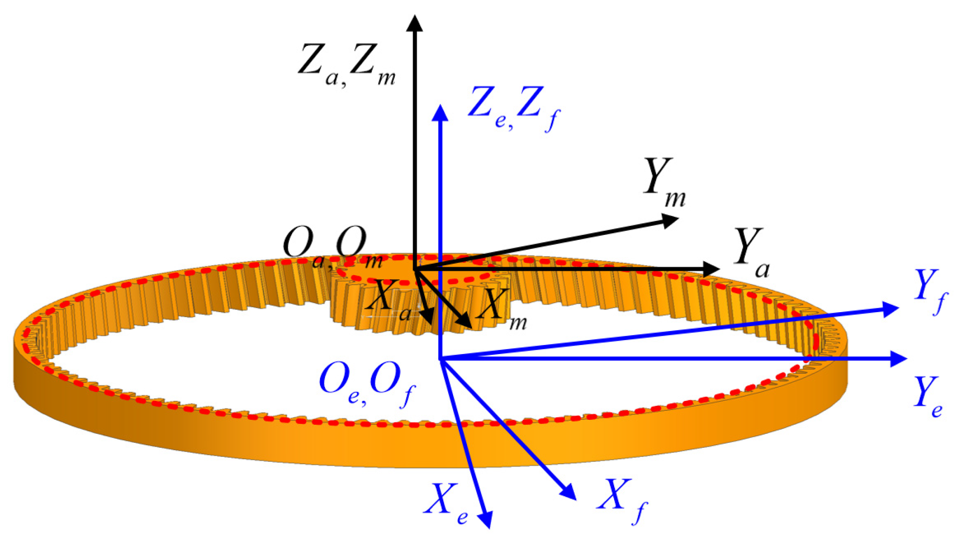
Based on the kinematic relationship between the internal helical gear and the equivalent helical gear, the coordinate systems are constructed, as illustrated in Figure 6.
In the figure, the coordinate system O a - X a Y a Z a is the fixed coordinate system of the equivalent helical gear, and the coordinate system O m - X m Y m Z m is the moving coordinate system of the equivalent helical gear; the equivalent helical gear rotates about the axis O m Z m with a rotation angle of Φ m .
The coordinate system O e - X e Y e Z e is the fixed reference coordinate system, and the coordinate system is O f - X f Y f Z f the moving coordinate system of the internal helical gear; the internal helical gear rotates about the axis O f Z f with a rotation angle of Φ f . L denotes the distance between the coordinate origins of the internal helical gear and the equivalent helical gear.
The transformation matrices between each coordinate system are as follows:
M a m = cos ( Φ m ) sin ( Φ m ) 0 0 sin ( Φ m ) cos ( Φ m ) 0 0 0 0 1 0 0 0 0 1 ,   M e a = 1 0 0 L 0 1 0 0 0 0 1 0 0 0 0 1 M f e = cos ( Φ f ) sin ( Φ f ) 0 0 sin ( Φ f ) cos ( Φ f ) 0 0 0 0 1 0 0 0 0 1
The following can be derived from the kinematic relationship between the equivalent helical gear and the internal helical gear:
Φ f N f = Φ m N m
where N f is the tooth number of the internal helical gear and N m is the tooth number of the equivalent helical gear.
The homogeneous transformation matrix for the equivalent helical gear enveloping the tooth of the internal helical gear is expressed as follows:
M f m = M f e M e a M a m
Take the topologically modified tooth flank of the equivalent helical gear as the generating surface to generate the topologically modified tooth flank of the internal helical gear via enveloping.
Given that the topological modification tooth flank equation of the equivalent helical gear in the coordinate system O m - X m Y m Z m is r m ( μ , θ ) , after coordinate transformation corresponding to the gear shaping machining of the internal helical gear, the topological modification tooth flank equation of the internal helical gear can be derived as follows:
r f ( μ , θ , Φ m ) = M f m r m ( μ , θ )

4. Motion Control for Profile Modification of Spherical Worm Grinding Wheel and Teeth of Internal Helical Gear

4.1. Calculation of Motion for Profile Modification of Spherical Worm Grinding Wheel

(1)
Analysis of Profile Dressing Motion for Spherical Worm Grinding Wheel
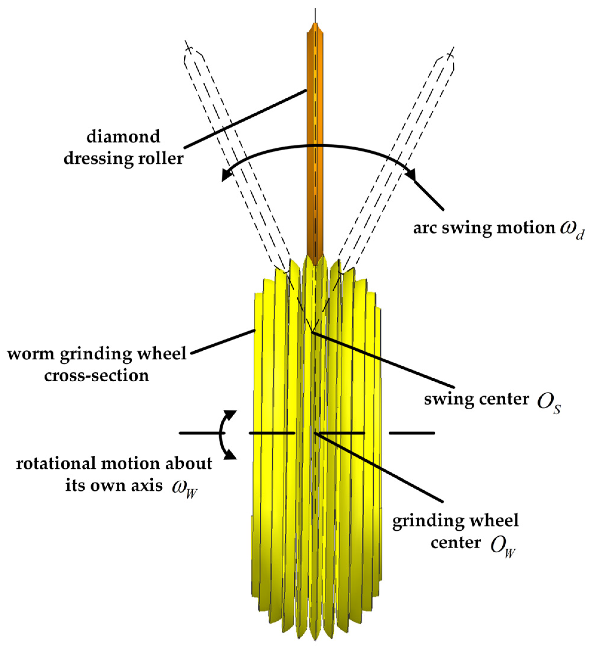
According to the forming principle of the spherical worm grinding wheel profile, its surface is generated by the helical motion of the generatrix on its normal cross-section. Assume a cutter whose axial section profile is consistent with the generatrix shape on the normal cross-section of the spherical worm grinding wheel. The cutter performs the identical helical motion around the blank of the worm grinding wheel, and the instantaneous contact line between the cutter and the spherical worm grinding wheel blank always lies on the same normal cross-section, with the generatrix coinciding with the contact line all the time. The material of the grinding wheel is removed with the movement of the diamond roller, thereby forming the helicoid of the worm grinding wheel. The kinematic relationship between the diamond roller and the spherical worm grinding wheel during dressing is shown in Figure 7.
The dressing process mainly consists of three motions: the rotational motion of the spherical worm grinding wheel about its own axis, the rotational motion of the formed diamond roller about its own axis, and the circular swing motion of the diamond roller around the swing center O s . The rotation of the grinding wheel ensures that the entire surface profile of the grinding wheel can be dressed. The rotation of the formed diamond roller provides cutting capacity for the roller, while the swing motion of the formed diamond roller guarantees that the worm grinding wheel is dressed with the correct profile. It should be noted that O w denotes the center of the grinding wheel, which does not coincide with the swing center O s of the diamond roller.
The calculation formulas for the rotational speed ω w of the worm grinding wheel rotating about its own axis and the rotational speed ω d of the circular swing motion of the diamond roller are expressed as follows:
ω d ω w = 1 i w s = N w N s
where i w s represents the transmission ratio between the equivalent helical gear corresponding to the spherical worm grinding wheel and the grinding wheel; N s denotes the number of teeth of the equivalent helical gear; and N w denotes the number of starts of the worm grinding wheel.
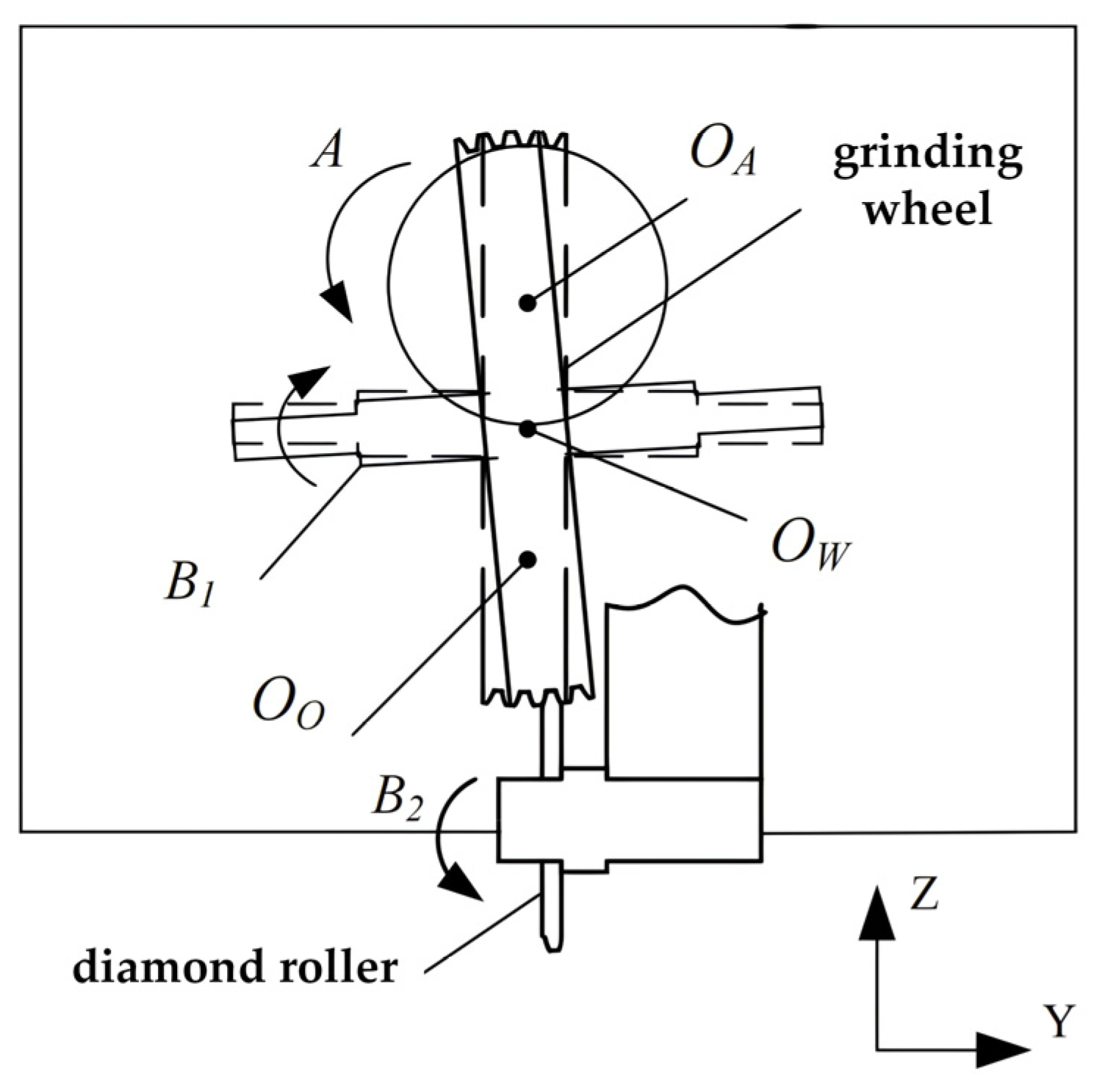
In the actual dressing process, the diamond roller is generally fixedly mounted, and its circular swing motion cannot be controlled by motion axes. Therefore, the motion of the diamond roller needs to be converted into the motion of the spherical worm grinding wheel. The motion mode of the worm grinding wheel is illustrated in Figure 8.
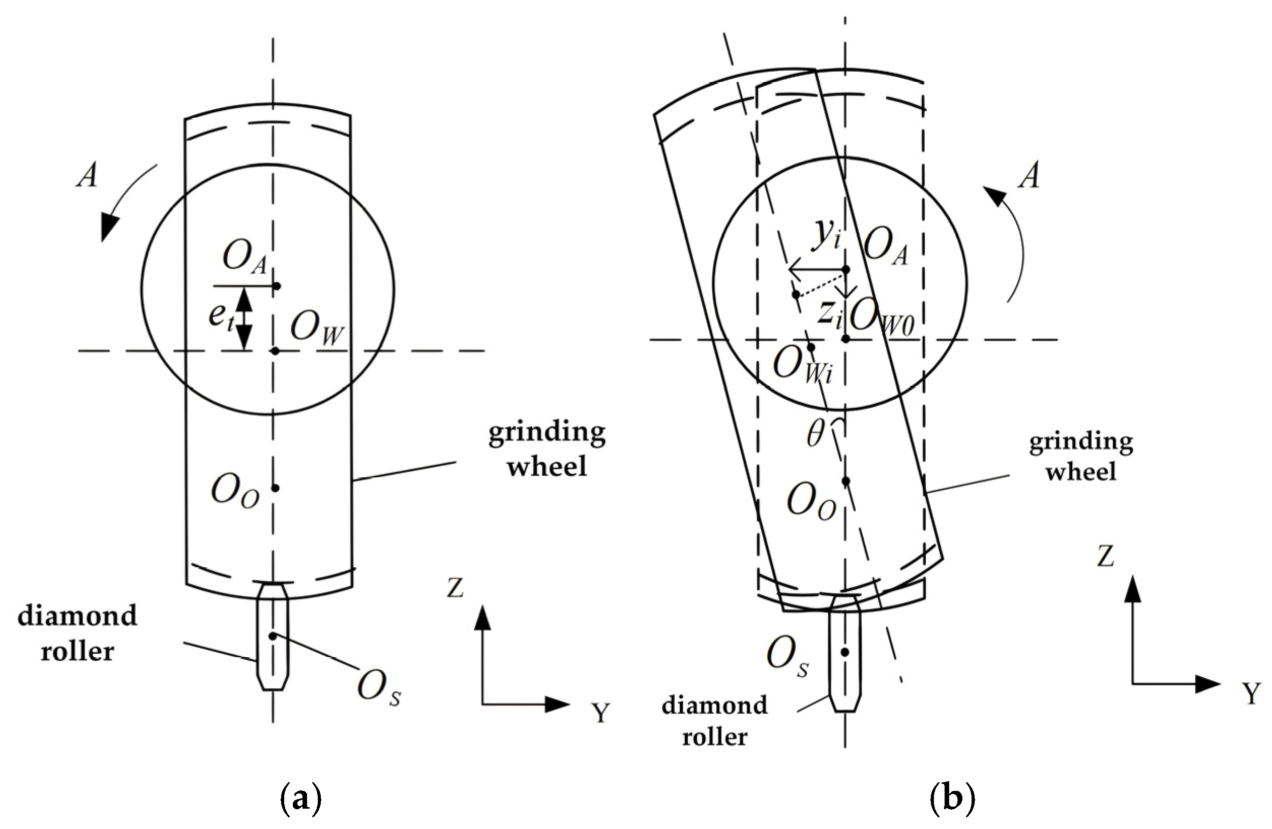
During dressing, the worm grinding wheel performs eccentric oscillation relative to the roller in the vertical plane ( O O denotes the oscillation center). Based on the machining principle of virtual center distance, the eccentric oscillation of the spherical worm grinding wheel can be decomposed into two motions. The first is the translation of the grinding wheel within the Y-Z plane, realized by the coordinated motion of the tangential feed axis Y and the axial feed axis Z. The second is the rotary motion of the spherical worm grinding wheel about the center O A of axis A. In conclusion, four-axis coordinated motion of axes Z, Y, A and B1 is required to realize the dressing motion of the helicoid of the worm grinding wheel.
Based on the characteristics of dressing motion, the motion for dressing the spherical worm grinding wheel is simplified and described, as shown in Figure 9.
In the figure, O S and O W lie on the same vertical straight line within the plane. O A is the rotation center of axis A. A fixed offset e t exists vertically between O A and O W . According to the motion decomposition principle, the dressing motion of the grinding wheel can be decomposed in the form illustrated in Figure 3. On this basis, the travel of each axis from the reference point “0” to point “i” for the grinding wheel can be calculated.
When the rotational angle of the grinding wheel is Δ a i , the rotation angle of the tool post is θ . The displacement of the A-axis center O A along the Y-axis is y i , and its displacement along the Z-axis is z i , which drives the grinding wheel center to reach O W i . The relationships between the travels of axes A, Y, Z and the travel of axis B1 can be expressed as
θ = Δ a i / N s y i = ( E + e t ) ( 1 cos θ ) z i = ( E + e t ) sin θ
where E is the distance between the worm grinding wheel center O W and the oscillation center O O , and e t is the distance between the worm grinding wheel center O W and the rotation center O A of axis A.
(2)
Numerical Calculation of Dressing Motion for Profile of Spherical Worm Grinding Wheel
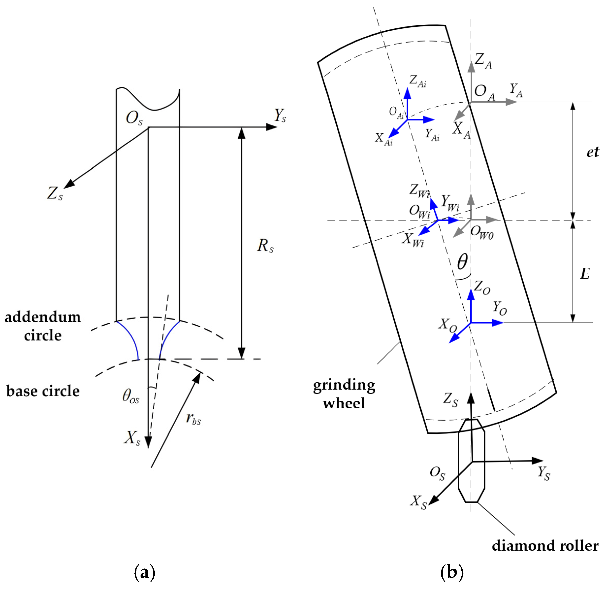
As can be seen from the forming dressing principle of the worm grinding wheel, the surface profile of the spherical worm grinding wheel is generated by the envelope of the dressing roller. Nevertheless, the surface profile of the dressing roller is a three-dimensional curved surface. Therefore, equations with two surface parameters are required to describe the roller surface profile in mathematical calculation, and one motion parameter should be introduced during the grinding wheel dressing motion. In summary, after homogeneous coordinate transformation is performed on the roller profile, the profile of the spherical worm grinding wheel contains three unknown parameters. Since the self-rotary motion of the dressing roller during dressing does not alter the shape and spatial position of its axial section profile, the three-dimensional spatial curved profile of the roller is converted into a two-dimensional plane curve in this manuscript, which reduces one unknown parameter in calculation. The sectional tooth profile of the dressing roller is shown in Figure 10a, and its expression is
r s = x s y s z s 1 = r b s cos ( θ o s + θ s ) + ( θ s + Δ L ) sin ( θ o s + θ s ) + r b s + R s r b s sin ( θ o s + θ s ) ± ( θ s + Δ L ) cos ( θ o s + θ s ) 0 1
where r b s denotes the base circle radius of the involute on the axial section of the dressing roller, θ o s represents the angle between the axis of symmetry of the involute and the starting point of the involute, θ s is the variable parameter of the involute, and R s stands for the radius of the dressing roller. The symbol “+” corresponds to the right involute, while “−” corresponds to the left involute.
Forming dressing of the spherical worm grinding wheel is carried out on the worm grinding wheel gear grinder based on the virtual center distance principle. The coordinate transformation relations are shown in Figure 10b.
In the figure, O S - X S Y S Z S is the coordinate system fixed to the roller, O A - X A Y A Z A denotes the initial coordinate system of the rotation center of axis A, O A i - X A i Y A i Z A i is the moving coordinate system of the rotation center of axis A, O W i - X W i Y W i Z W i stands for the coordinate system of the worm grinding wheel, O W - X W Y W Z W is the moving coordinate system of the worm grinding wheel, and O O - X O Y O Z O refers to the coordinate system of the virtual oscillation center of the worm grinding wheel.
The corresponding homogeneous coordinate transformation matrices are solved according to the positional relationships among each coordinate system shown in the figure. The transformation matrix from the coordinate system O S - X S Y S Z S to the coordinate system O W i - X W i Y W i Z W i is
M A S = 1 0 0 0 0 1 0 0 0 0 1 E t 0 0 0 1 M A A = 1 0 0 0 0 1 0 z i 0 0 1 y i 0 0 0 1 M A i A = 1 0 0 0 0 cos θ sin θ 0 0 sin θ cos θ 0 0 0 0 1
M W i A i = 1 0 0 0 0 1 0 e t sin θ 0 0 1 e t cos θ 0 0 0 1 M W W i = cos Δ a i 0 sin Δ a i 0 0 1 0 0 sin Δ a i 0 cos Δ a i 0 0 0 0 1
From the homogeneous coordinate transformation matrices between the various dressing coordinate systems solved above, it can be concluded that there exists only one independent motion parameter, Δ a i , during the dressing process of the spherical worm grinding wheel. Therefore, when dressing the worm grinding wheel on the gear grinding machine, the total homogeneous coordinate transformation matrix from the moving coordinate system of the dressing roller to the moving coordinate system of the worm grinding wheel can be expressed as
M W S ( Δ a i ) = M W W i M W i A i M A i A M A A M A S
The tooth surface of the dressed worm grinding wheel calculated accordingly is
r W S ( θ S , Δ a i ) = M W S r S ( θ S )
where Δ a i in matrix M W W i denotes the rotation angle of axis B1.

4.2. Realization of Topological Generating Grinding Motion for Internal Helical Gear Teeth

Generating grinding of internal helical gears with a spherical worm grinding wheel is essentially the meshing process of a pair of internal helical gear pairs. The high-speed rotation of the grinding wheel produces the rotation of the equivalent helical gear. The tooth trace feed motion of the internal helical gear can be realized by the coordinated motion of the axes Z and C; the tooth trace modification of the internal helical gear can be realized by the coordinated motion of the axes Z and X; and the generating grinding motion of the internal helical gear can be realized by the coordinated motion of the axes B1 and C. Therefore, when the axes Y and A are adjusted to the required positions, four-axis coordinated motion of the axes Z, C, X and B1 is required to achieve the topological modification generating grinding machining of the tooth surface of the internal helical gear.
During generating grinding, high-speed coordinated motion among the spherical worm grinding wheel, the equivalent helical gear and workpiece establish a meshing transmission relationship. On the one hand, the grinding wheel moves along the workpiece axis from one end face of the workpiece to the other, generating grinding motion along the tooth space and completing the forming of the entire gear tooth surface. On the other hand, the grinding wheel needs to move radially relative to the workpiece following a “deep-shallow-deep” trajectory to realize motion control for tooth trace modification of the gear tooth surface. Owing to the helix angle of the internal helical gear, additional rotation occurs for the equivalent helical gear during axial feed along the workpiece, which makes the grinding wheel rotate at a higher rotational speed under a specific transmission ratio. The mounting angle A of the grinding wheel is calculated as
A = β + λ n
When machining spur cylindrical gears, to maintain correct meshing motion during gear grinding, the rotational speeds of the grinding wheel and gear blank must satisfy a specific transmission relationship. That is, when the gear blank rotates by one revolution, the rotational speed n w of the grinding wheel is
n w = N f N n
When grinding internal helical gears, either the grinding wheel or the gear blank needs to perform a certain amount of additional rotation due to the lead. The rotational speed n of the gear when machining internal helical gears with a spherical worm grinding wheel is
T = π d f cot β n = 1 + S n T
where S n is the axial travel of the grinding wheel along the workpiece per revolution of the gear blank and S n = 1 mm/r is adopted; T is the lead of the internal helical gear and d f denotes the reference circle diameter of the internal helical gear.
To realize tooth trace modification on the tooth surface of the internal helical gear, the spherical worm grinding wheel performs grinding motion along a second-order parabolic trajectory within the X–Z plane. Firstly, the initial coordinate values along the X-axis and Z-axis are determined and denoted as G and H. It should be noted that the initial X-axis coordinate G corresponds to the coordinate value when the modification amount equals zero. The moving distance along the Z-axis is L, and the moving distance along the X-axis is Δ E . The time-varying coordinates of the X-axis and Z-axis are, respectively,
X t = G P 2 θ 2 Z t = G 0.0008 ( L b 2 ) 2

5. Numerical Tooth Surface Calculation of Spherical Worm Grinding Wheel and Internal Helical Gear

To verify the validity of the tooth surface topological modification control method proposed in this manuscript, a numerical example is introduced for calculation and verification. The basic parameters of the spherical worm grinding wheel are listed in Table 1. It should be noted that the calculation example selected in this manuscript comes from a commercial automobile, and the maximum tooth profile modification is 0.006 mm. According to formula (1), the corresponding modification coefficient a1 can be calculated, and the modification coefficient b1 is based on the actual demand, and the position where the geometric transmission error is 0 is slightly corrected.
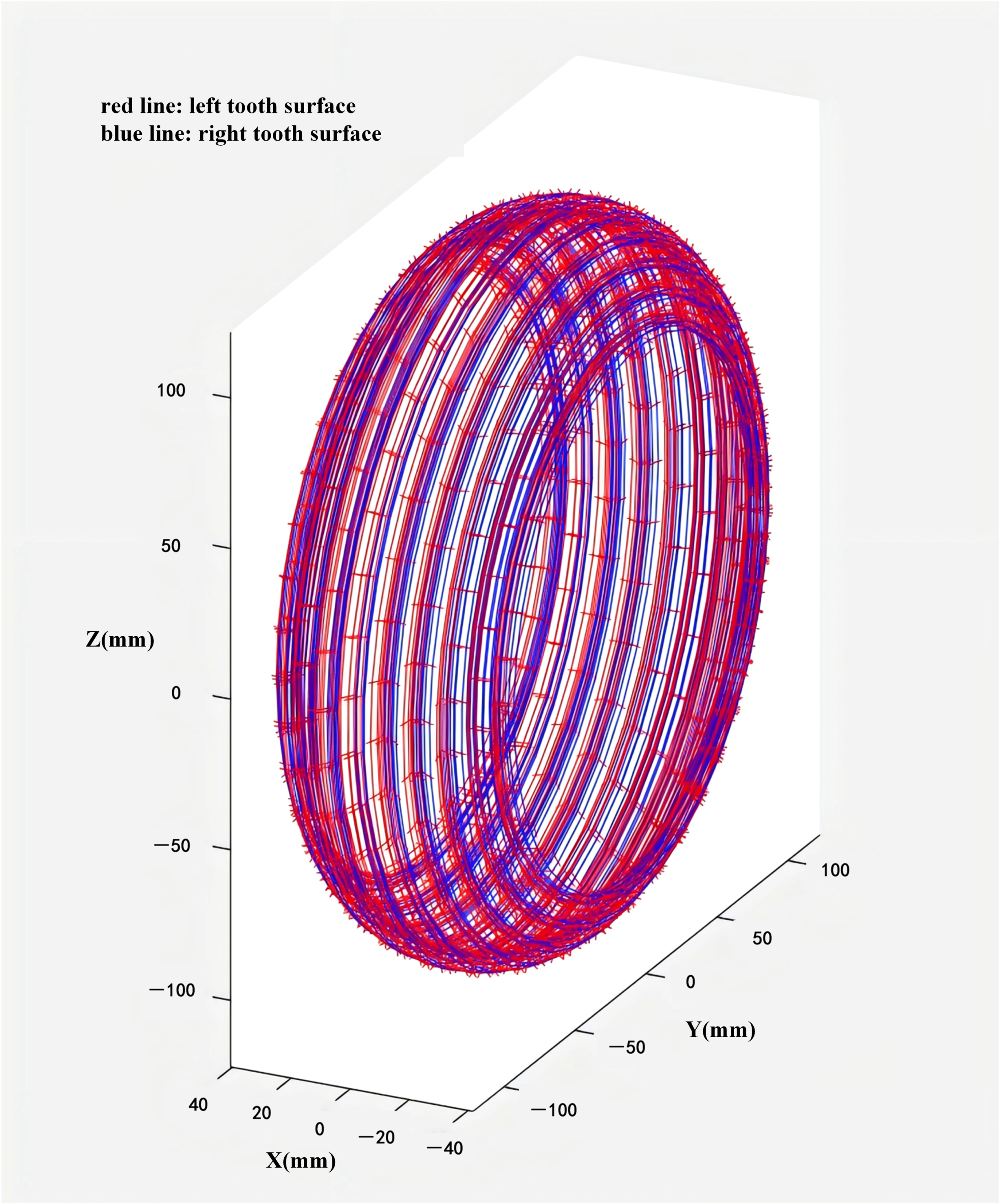
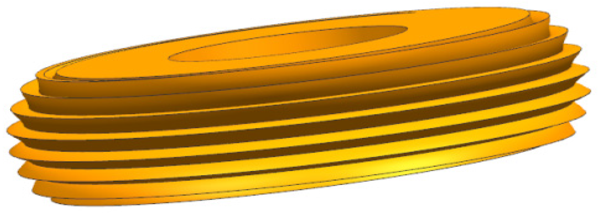
The tooth profiles of the spherical worm grinding wheel before and after modification are calculated and three-dimensional modeling is carried out by adopting the method proposed in this manuscript, as shown in Figure 11 and Figure 12.
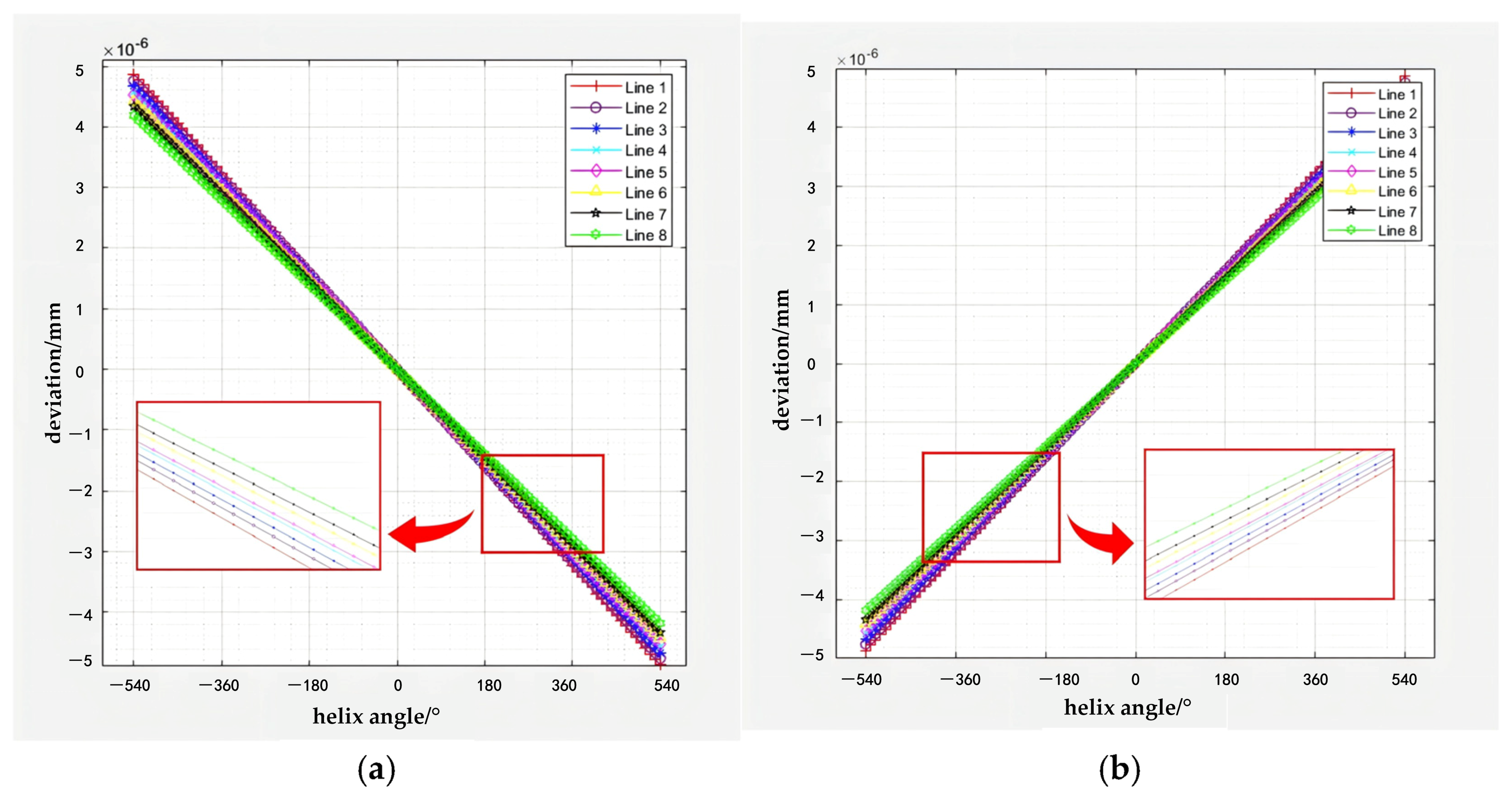
Eight helix curves are selected on both lateral surfaces along the tooth height direction. The normal deviations between the modified surface and the theoretical surface along the helix direction are calculated, and the calculation results are shown in Figure 13.
It can be seen from the figure that the deviation value increases linearly from the middle of the grinding wheel surface toward both sides, and the deviation values of the left and right profiles are opposite. The maximum deviations of the left and right profiles on the eight helix curves are listed in Table 2.
It can be seen from Table 2 that Line 1 corresponds to the curve with the maximum deviation. The maximum deviations of the left and right profiles are 4.813 × 10⁻⁶ mm and 4.796 × 10⁻⁶ mm, respectively. All maximum deviation values are less than 5 × 10⁻⁶ mm. The results verify the correctness and feasibility of the grinding wheel dressing method based on the virtual center distance principle.
Based on the derived mathematical model for topological modification of internal helical gears, calculations and modeling of modified internal helical gears are carried out with a specific numerical example. The basic parameters and modification coefficient values of the equivalent helical gear and internal helical gear are listed in Table 3. According to the actual use requirements of the gear, the tooth profile and tooth length modification corresponding to the modification coefficient in the table are 0.006 mm and 0.007 mm respectively.
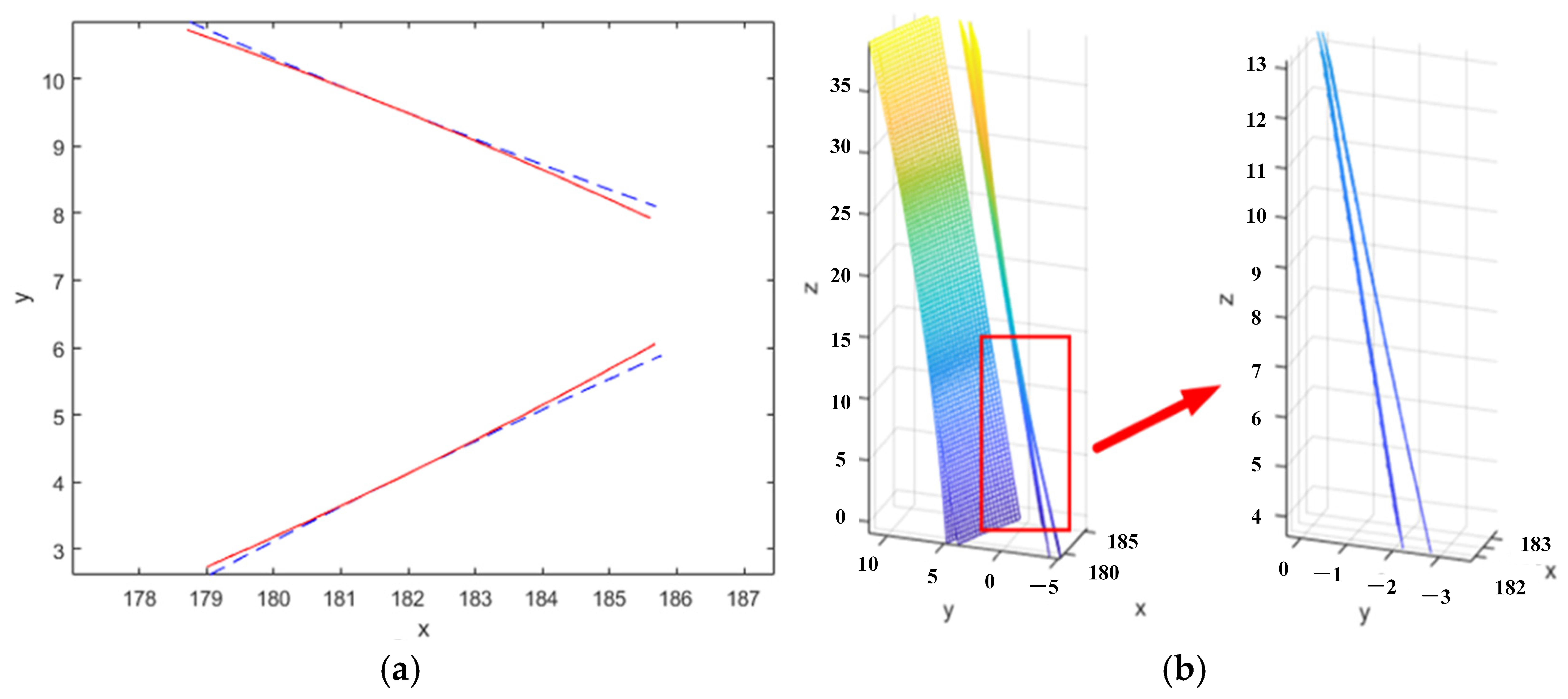
Based on the above parameters, the comparison of the tooth surfaces of the internal helical gear before and after topological modification is calculated and shown in Figure 14. The X-axis denotes the radial direction of the internal helical gear, the Y-axis represents the tooth-height direction of the gear tooth, and the Z-axis corresponds to the face-width (tooth lead) direction of the gear.
According to the calculation principle of the mounting angle and the coordinated motion relationship among each travel axis analyzed above, the calculated motion parameters for the generating machining of internal helical gears are listed in Table 4.
It can be seen from the above table that the coordinated motion relationship among the axes Z, C and B1 is as follows: when the grinding wheel moves 1 mm along the Z-axis, the axis C rotates by 1.000153538699 revolutions, and the axis B1 rotates by 120 revolutions simultaneously. It should be noted that the above four-axis motions proceed simultaneously, thereby realizing tooth trace modification, feed motion and generating grinding motion of the internal helical gear during the grinding process.

6. Experimental Verification

6.1. Machining Equivalence Analysis of External Cylindrical Gear and Internal Helical Gear

Internal gears suffer from inherent structural restrictions. The motor-direct-drive spindle of the grinding wheel cannot stretch into the inner space of the ring gear. In addition, motor installation schemes using belt or gear transmission cannot achieve high-speed precise linkage between the grinding wheel and the internal helical gear. Therefore, the method proposed in this manuscript will be verified in an indirect way.
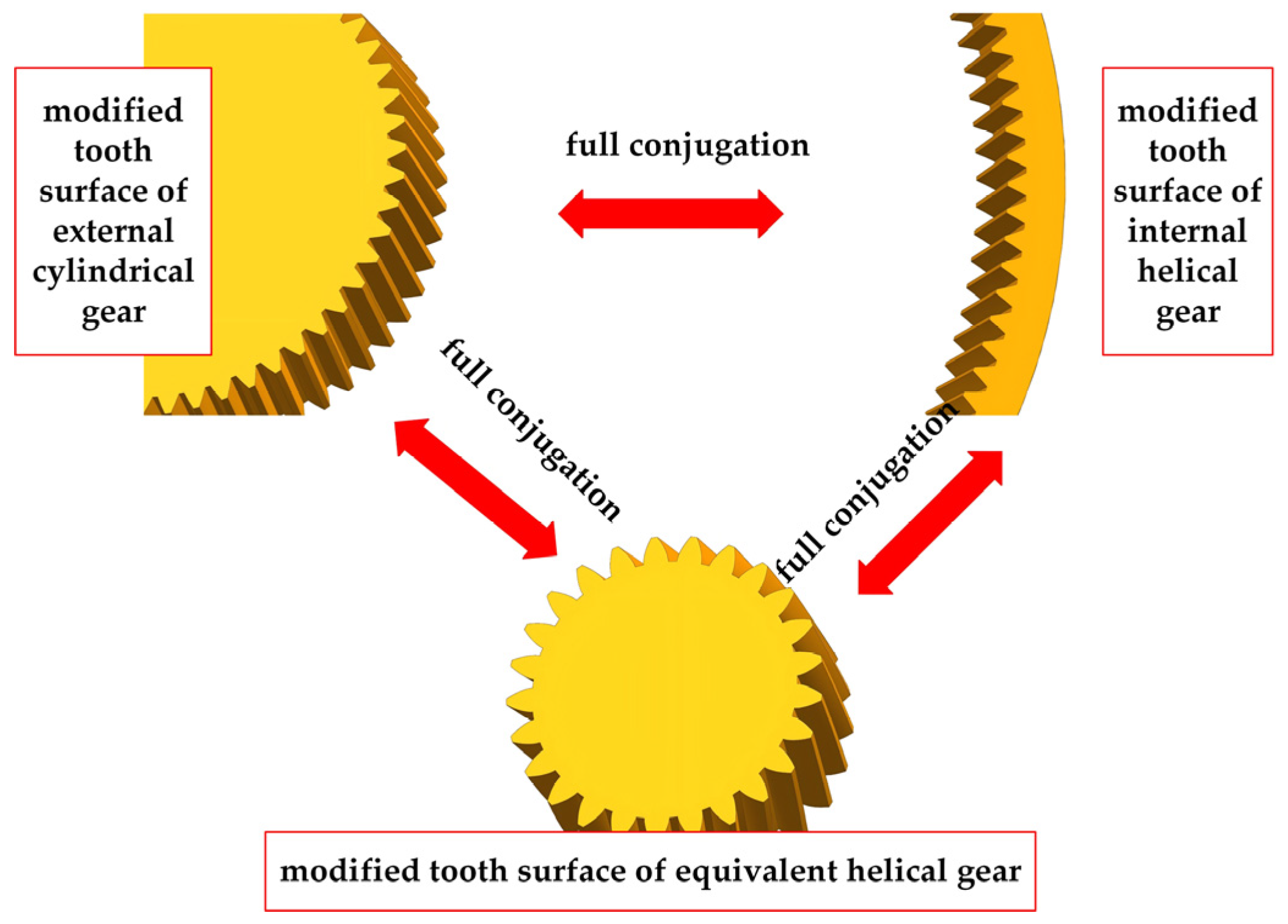
Nevertheless, indirect verification of the correctness of grinding wheel dressing and internal helical gear modification can be realized by grinding a specific external cylindrical gear. According to the geometric relationship between the equivalent helical gear and the internal helical gear, the profile of the equivalent helical gear coincides with the profile of the spherical worm grinding wheel. The tooth flank of the internal helical gear is generated from the modified tooth surface of the equivalent helical gear. The tooth flanks of the equivalent helical gear and the internal helical gear are fully conjugate with each other. Furthermore, the tooth surface of the external cylindrical gear deduced from the equivalent helical gear is also completely conjugate with that of the equivalent helical gear. In other words, the same spherical worm grinding wheel and identical generating relationship are adopted for the grinding of external cylindrical gears and internal helical gears. The tooth surfaces of the external cylindrical gear, equivalent helical gear and internal helical gear are mutually fully conjugate, as illustrated in Figure 15.
Therefore, generating grinding tests of external cylindrical gears are carried out using a spherical worm grinding wheel for indirect verification. This test scheme validates both the performance of the grinding wheel dressing technology and the topological-control approach for the generating tooth flanks of internal helical gears. The external cylindrical gear shares identical module, helix angle, pressure angle, tooth width and modification parameters with the internal helical gear, and its geometric parameters are listed in Table 5.

6.2. Dressing of Spherical Worm Grinding Wheel and Generating Grinding of Internal Helical Gear

To further verify the rationality of the aforementioned grinding wheel dressing method, grinding wheel dressing experiments were carried out on the YK7363 gear grinding machine (Chongqing Machine Tool Group Co., Ltd., Chongqing, China). The machine tool features an eight-axis five-linkage configuration equipped with the SINUMERIK 828D CNC system (Siemens AG, Munich, Germany). Its machining accuracy is steadily maintained at Grade 6, which satisfies the requirements for spherical worm grinding wheel dressing and generating grinding of modified helical gears.
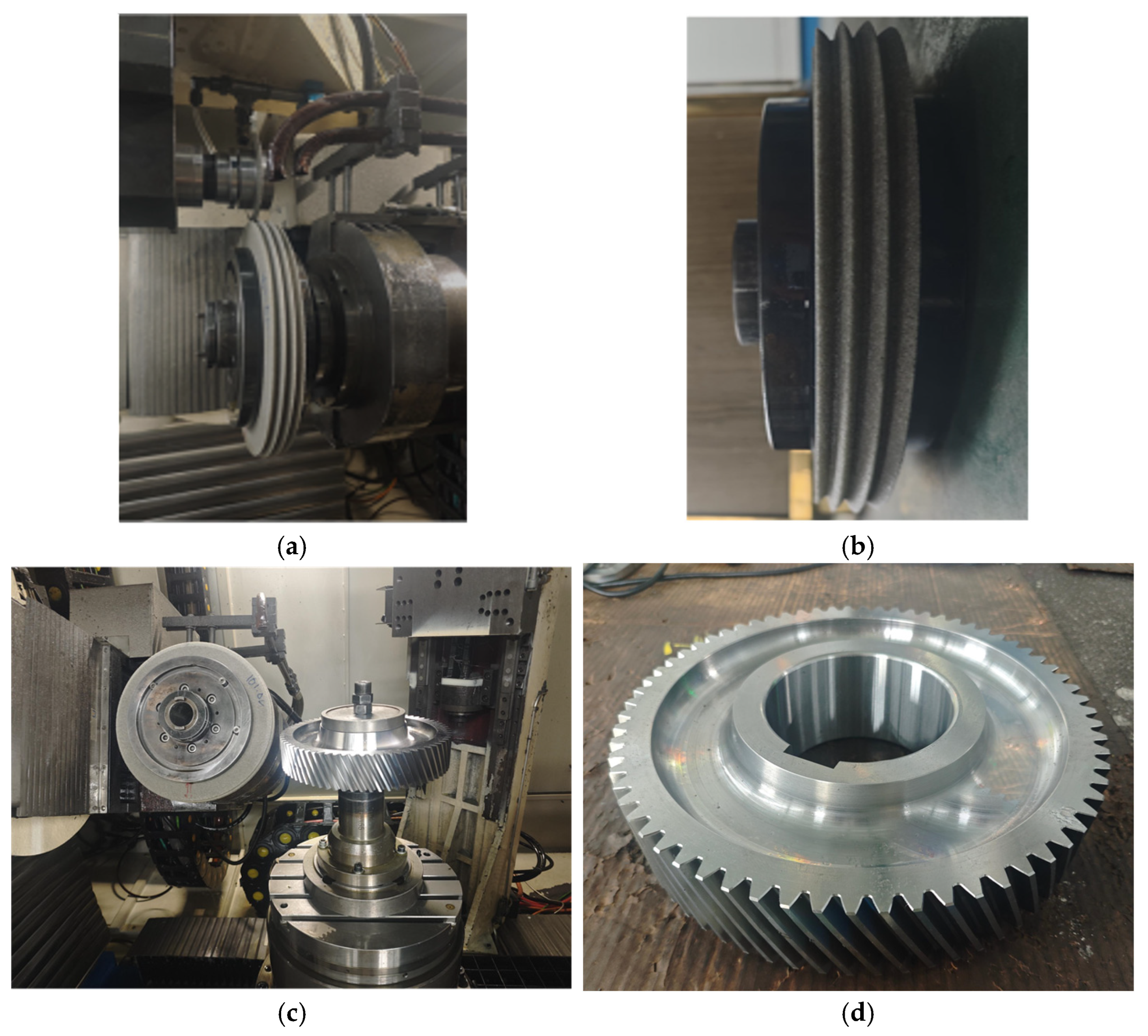
Based on the machining principle of virtual center distance, the diamond roller is arranged directly above the grinding wheel during dressing, so that the worm grinding wheel performs eccentric oscillation relative to the diamond roller in the vertical plane. The dressing process consists of rough dressing followed by finish dressing to further improve the surface precision of the grinding wheel. The dressing process of the spherical worm grinding wheel is shown in Figure 16a, and the dressed spherical worm grinding wheel is presented in Figure 16b.
The modification mode, grinding motion control strategy and basic geometric parameters adopted for machining external cylindrical gears and internal helical gears with worm grinding wheels are identical. Therefore, the topologically modified tooth surfaces of the external cylindrical gear and the internal helical gear are fully conjugate. Accordingly, the topological measurement results of gear teeth after generating grinding of the external cylindrical gear can verify the feasibility and accuracy of both the dressing method for spherical worm grinding wheels and the generating gear grinding process. The grinding state and the machined cylindrical gear are shown in Figure 16c and Figure 16d respectively.
In the process of gear grinding, the grinding parameters used are shown in Table 6.

6.3. Tooth Surface Deviation Measurement

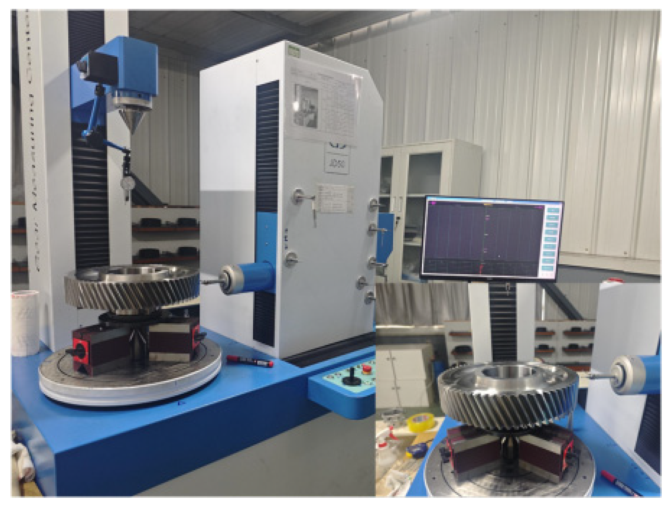
Gear tooth surface precision inspection is carried out using the JD50 gear measuring center (produced by Harbin Jingda Measuring Instrument Co., Ltd., Harbin, China). This equipment integrates an intelligent measurement and analysis software module and is equipped with a Renishaw SP80H 3-D scanning probe (Renishaw plc, Wotton-under-Edge, UK), featuring automatic adaptation to styluses of multiple specifications. The repeated positioning accuracy of each axis is less than 0.5 μm, the measurement uncertainty of tooth profile shape deviation is less than 0.5 μm, and the tooth inclination deviation is less than 0.4 μm. The specific measurement state is shown in Figure 17. The measurement of gear accuracy is based on Chinese national standard GB/T 10095-1988 [23].
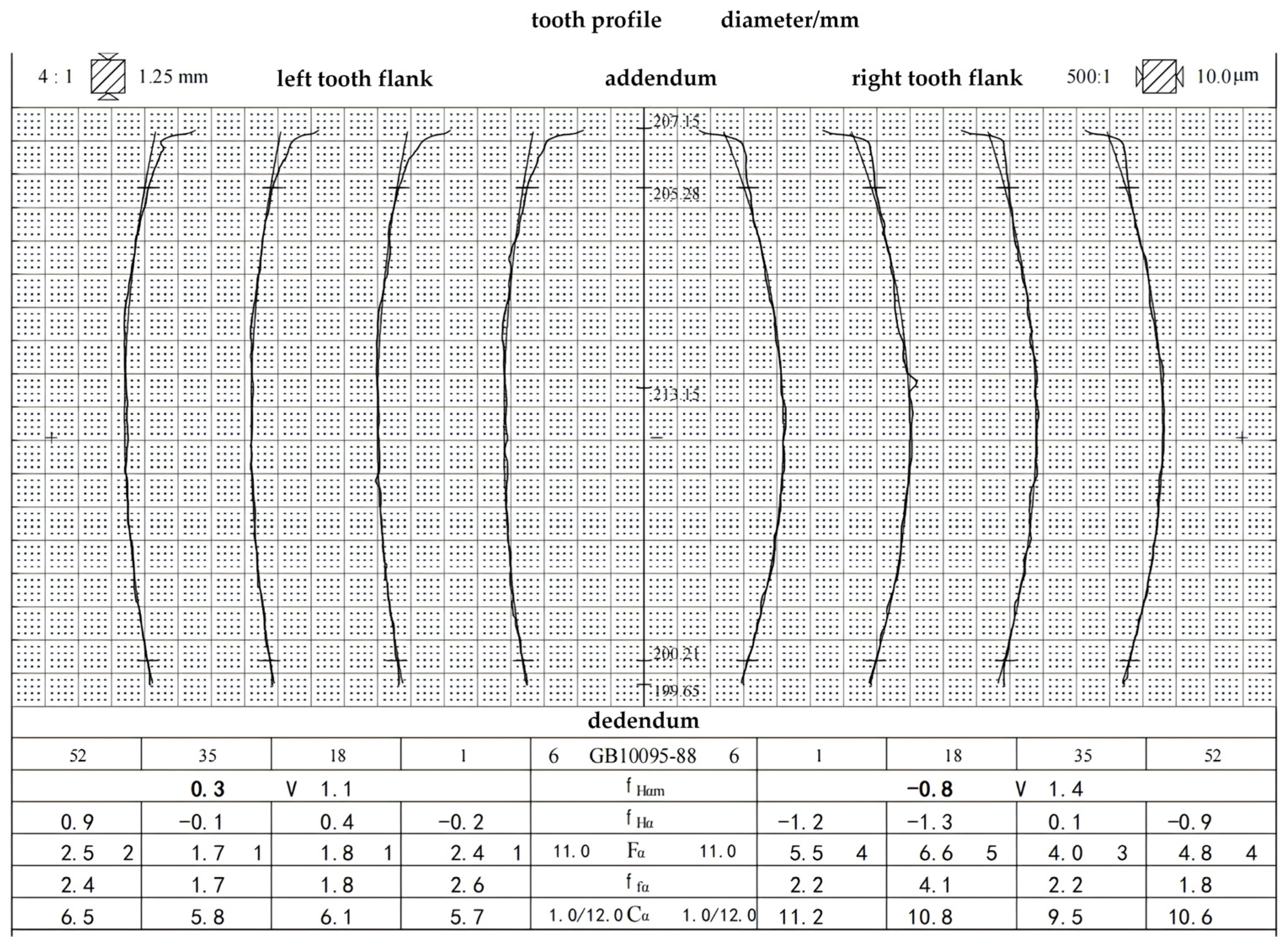
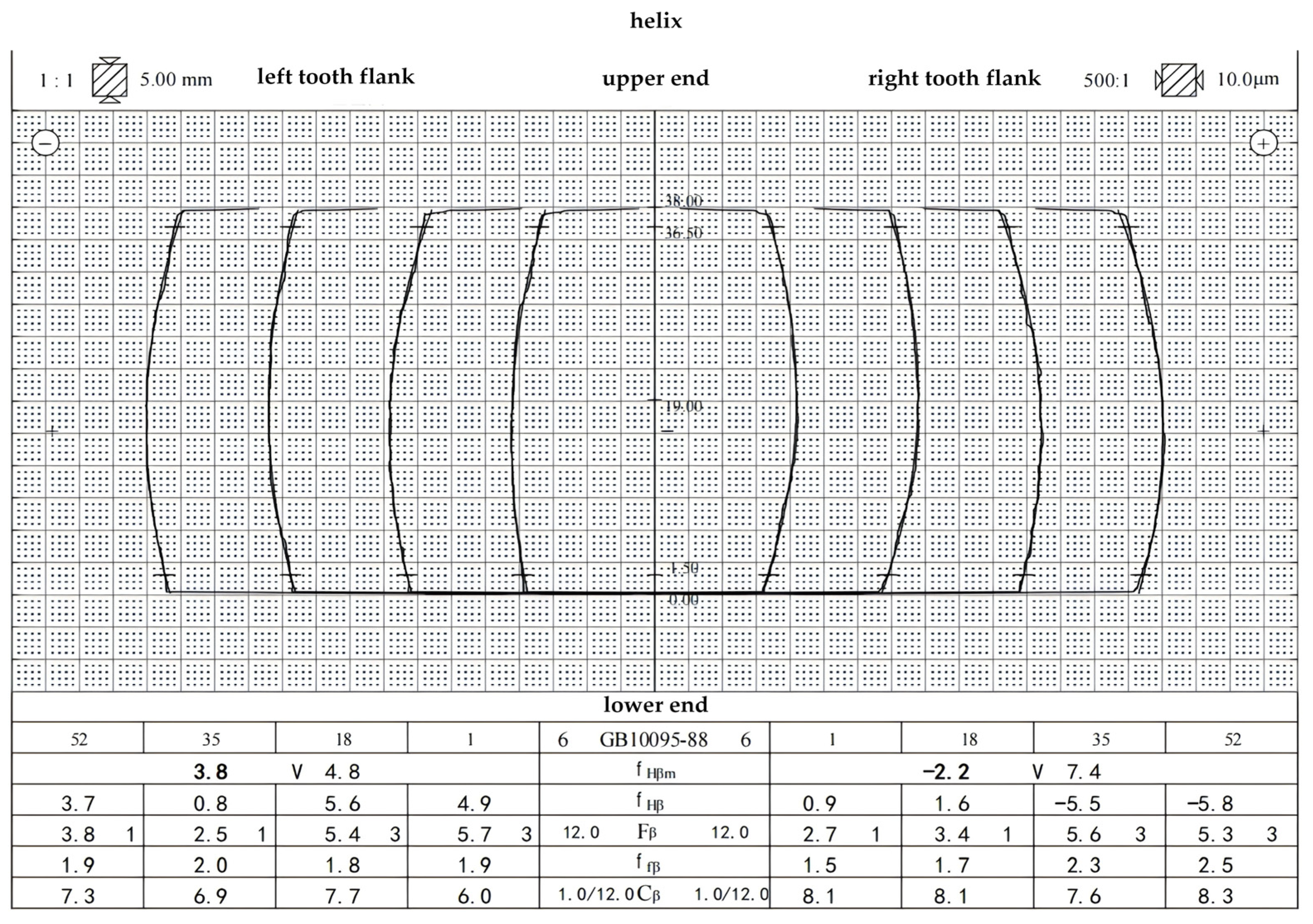
It can be seen from Figure 18 that for the right tooth flank of the gear, the total profile deviation F α is 6.6 μ m , the profile slope deviation f H α is −1.3 μ m , and the profile form deviation f f α is 4.1, corresponding to Grade 5 profile accuracy. For the left tooth flank of the gear, the total profile deviation F α is 2.5, the profile slope deviation f H α is 0.9, and the profile form deviation f f α is 2.6, corresponding to Grade 2 profile accuracy. It can be seen from Figure 19 that for the right tooth flank of the gear, the total lead deviation F β is 5.6, the lead slope deviation f H β is −5.8, and the lead form deviation f f β is 2.5, corresponding to Grade 3 lead accuracy. For the left tooth flank of the gear, the total lead deviation F β is 5.7, the lead slope deviation f H β is 5.6, and the lead form deviation f f β is 2.0, corresponding to Grade 3 lead accuracy.
Inspections are carried out on the tooth profile and tooth lead of gears processed by generating grinding. The measurement results are presented in Figure 18 and Figure 19.
Through gear grinding tests and tooth surface deviation measurement of the external cylindrical gear, the obtained tooth surface modification accuracy reaches Grade 5, which meets actual production requirements. Since the topologically modified tooth surfaces of the external cylindrical gear and internal helical gear are fully conjugate and their modification machining modes are identical, the test results verify the accuracy of the forming dressing method for spherical worm grinding wheels based on the virtual center distance principle proposed in this manuscript, as well as the feasibility of the generating gear grinding technology.
It should be noted that the above experimental verification is completed by indirect equivalent experiments on an external cylindrical gear. Restricted by the existing machine tool structural layout, the spindle assembly of the spherical worm grinding wheel cannot extend into the inner cavity of the internal helical ring-gear workpiece. For this reason, direct generating grinding experiments for internal helical gears cannot be carried out in the present work.
Under identical modification parameters, dressing parameters and generating grinding kinematic relationships, the tooth flanks of the external cylindrical gear and the target internal helical gear are fully conjugate. Hence, the external gear grinding test can verify the effectiveness of the proposed grinding wheel dressing algorithm and multi-axis motion control strategy.
Nevertheless, this indirect verification scheme has inherent limitations. Contact stiffness, heat dissipation conditions and workpiece interference boundaries occurring in practical internal helical gear grinding cannot be completely reproduced by external gear grinding. Differences in workpiece clamping conditions will cause distinct elastic deformation of the tool-workpiece system, which may introduce extra unevaluated machining deviations for real internal ring-gear processing.
Therefore, the experimental results can validate the theoretical algorithm, but cannot fully reflect all practical error sources of real internal helical gear generating grinding. At the same time, although this method is not affected by the geometric parameters of the gear, it is restricted by the spatial structure of the grinding wheel frame. When the gear modulus is too small, the grinding wheel frame cannot extend into the internal gear. When the helix angle of the gear is too large, the grinding wheel frame will interfere with the end face of the internal gear. Therefore, the machining range of this method will be restricted by modulus and helix angle. In future work, machine tool retrofitting will be implemented to conduct direct grinding experiments of internal helical gears for further validation.

7. Conclusions

Based on the conjugate surface envelope theory and spatial meshing principle, this manuscript completes the modification calculation for the profile of spherical worm grinding wheels and the tooth topology of internal helical gears. A numerical example is introduced to calculate discrete points on modified tooth surfaces of the spherical worm grinding wheel and internal helical gear, as well as to establish their geometric models. The motion control for dressing machining of spherical worm grinding wheel profiles and tooth topology of internal helical gears is realized. By investigating the implementation approaches of spherical worm grinding wheel dressing and generating grinding of internal helical gears, equivalent generating modification machining experiments of the spherical worm grinding wheel and gears are carried out. The experimental results verify the feasibility of the proposed modification method and provide a theoretical foundation for high-efficiency machining of internal helical gears.

Author Contributions

Conceptualization, C.J. and Y.Z.; methodology, C.J. and Y.Z.; software, C.J. and J.Y.; validation, C.J. and Y.Z.; formal analysis, C.J.; investigation, C.J.; resources, Y.Z.; data curation, C.J. and J.Y.; writing—original draft preparation, C.J.; writing—review and editing, Z.H.; and Z.H.; visualization, C.J.; supervision, Y.S.; project administration, C.J.; funding acquisition, C.J. and Y.Z.; All authors have read and agreed to the published version of the manuscript.

Funding

The research is funded by National Natural Science Foundation of China (No. 52675065, No. 52005157, No. 52175049); Key R&D Special Project of Henan Province (No. 251111241400); Major Science and Technology Project of Henan Province (No. 241100220300).

Data Availability Statement

The data presented in this study are available on request from the corresponding author due to the fact that they are part of an ongoing project and have not yet been publicly archived.

Acknowledgments

The authors would like to thank all the authors of the references that gave us inspiration and help. The authors are grateful to the editors and anonymous reviewers for their valuable comments that improved the quality of this manuscript.

Conflicts of Interest

The authors declare that they have no competing interests.

References

  1. Tan, J.J.; Li, H.; Yang, S.Y.; Zhu, C.C.; Song, C.S.; Sun, Z.D. Study on Unbalanced Meshing Loads of Planetary Gear Transmission under Heavy-load Conditions. China Mech. Eng. 2023, 34, 1513–1524. [Google Scholar] [CrossRef]
  2. Chen, Z.; Lei, B.; Zeng, M.; Li, Y.; Fuentes-Aznar, A. Computerized design, simulation of meshing and stress analysis of pure rolling internal helical gear drives with combined tooth profiles. Mech. Mach. Theory 2022, 176, 104959. [Google Scholar] [CrossRef] [Scilit]
  3. Han, J.; Yuan, B.; Wang, D.L.; Liang, H.; Xia, L. Comparative Experimental Study on Cutting Mechanism between Gear Honing and Grinding Process. J. Mech. Eng. 2018, 54, 205–213. [Google Scholar] [CrossRef]
  4. Jia, K.; Zheng, S.; Guo, J.K.; Hong, J. A Method of Cutter Profile Identification and Machining Motion Simulation for Skiving. J. Mech. Eng. 2019, 55, 216–224. [Google Scholar] [CrossRef] [Scilit]
  5. Guo, E.K.; Hong, R.J.; Huang, X.D.; Fang, C.G. A correction method for power skiving of cylindrical gears lead modification. J. Mech. Sci. Technol. 2015, 29, 4379–4386. [Google Scholar] [CrossRef] [Scilit]
  6. Guo, E.K.; Hong, R.J.; Huang, X.D.; Fang, C.G. Research on the cutting mechanism of cylindrical gear power skiving. Int. J. Adv. Manuf. Technol. 2015, 79, 541–550. [Google Scholar] [CrossRef] [Scilit]
  7. Yoshikoto, Y.; Masaharu, K.; Masashi, O. Grinding of internal gears by setting a large crossed-axes angle using a barrel-shaped grinding wheel. Precis. Eng. 2018, 52, 384–391. [Google Scholar] [CrossRef] [Scilit]
  8. Han, J.; Jiang, H.; Lu, Y.G.; Tian, X.Q.; Xia, L. Flexible Machining and Precision Control Method of Tooth Flank Topological Modification for Worm Wheel Gear Grinding. J. Mech. Eng. 2025, 61, 360–370. [Google Scholar] [CrossRef] [Scilit]
  9. Wang, L.T.; Zhao, X.X.; Li, J. Optimization of Machining Parameters for Gear Grinding with Worm Grinding Wheel. China Mech. Eng. 2021, 32, 2136–2141. [Google Scholar] [CrossRef]
  10. Wang, Z.H.; Song, X.M.; He, W.M.; Li, G.; Zhu, W.M.; Geng, Z. Construction of Tooth Surface Model and Error Evaluation for Helical Gear Form Grinding with Longitudinal Modification. China Mech. Eng. 2015, 26, 2841–2847. [Google Scholar] [CrossRef]
  11. Xia, L.; Shen, R.K.; Zhu, Y.G.; Han, J. Research on topological modification method of gear honing with powerful internal gear honing wheel. Hefei J. Hefei Univ. Technol. 2019, 42, 1585–1591. [Google Scholar] [CrossRef]
  12. Han, J.; Zhu, Y.; Xia, L.; Tian, X.Q. A novel gear flank modification methodology on internal gearing power honing gear machine. Mech. Mach. Theory 2018, 121, 669–682. [Google Scholar] [CrossRef] [Scilit]
  13. Denkena, B.; Schindler, A.; Woiwode, S. Calculation method of the contact area in flank machining for continuous generating grinding. Appl. Math. Model. 2016, 40, 7138–7146.8. [Google Scholar] [CrossRef] [Scilit]
  14. Su, J.X.; Jiang, C.; Nie, S.W.; Cheng, C. Experimental study on vibration characteristics of grinding wheel spindle in internal gear form grinding. J. Vib. Shock 2021, 40, 100–107. [Google Scholar] [CrossRef]
  15. Guo, H.; Zhao, N.; Xiang, Y.F.; Zhang, M.Q. Face Gear Grinding Method Using Six-axis CNC Worm Wheel Machine. J. Mech. Eng. 2015, 51, 186–194. [Google Scholar] [CrossRef] [Scilit]
  16. Ren, X.Z.; Li, H.K.; Su, J.X.; Li, Z.F. Optimization of grinding wheel profile for form grinding of modified internal helical gears. Mech. Des. Manuf. 2021, 366, 149–151+156. [Google Scholar] [CrossRef]
  17. Li, G.L.; Liu, P.X.; Zhou, H.Q.; Zhong, J.T. Continuous Generating Grinding Tooth Surface Texture Improvement Method for Noise Reduction. J. Mech. Eng. 2017, 53, 182–189. [Google Scholar] [CrossRef] [Scilit]
  18. Zhao, N.; Gao, H.; Guo, H. Double-parameter plane dressing method for face gear worm grinding wheel. Mach. Manuf. 2012, 50, 13–16. [Google Scholar] [CrossRef]
  19. Li, Y.; Wang, Z.H.; Liu, L.; Diao, X.W.; Wang, X.J. Effect of Topographic Modification Error Tooth Surface by Forming Method Double-sided Grinding on Gear Transmission. China Mech. Eng. 2022, 33, 1661–1669+1679. [Google Scholar] [CrossRef]
  20. Liao, J.; Xie, J.; Sun, J.X. Modeling of curved diamond wheel errors for improvement of freeform grinding accuracy. Int. J. Adv. Manuf. Technol. 2019, 103, 1879–1892. [Google Scholar] [CrossRef] [Scilit]
  21. Wang, S.; Zhao, Q.L.; Guo, B. Wear characteristics of electroplated diamond dressing wheels used for on-machine precision truing of arc-shaped diamond wheels. Diam. Relat. Mater. 2022, 129, 109372. [Google Scholar] [CrossRef] [Scilit]
  22. Li, G.L.; Ran, Q.F.; He, K.; Wang, S.L.; Cao, B. Forming dressing method for drum-shaped worm grinding wheel based on virtual center distance principle. Comput. Integr. Manuf. Syst. 2023, 29, 3394–3401. [Google Scholar] [CrossRef]
  23. GB/T 10095-1988; Accuracy of Gears. Standards Press of China: Beijing, China, 1988.
Figure 1. Kinematic relationship of internal helical gear grinding.
Processes 14 02947 g001
Figure 2. Transverse sectional view of the equivalent helical gear.
Processes 14 02947 g002
Figure 3. Coordinate system for gear modification.
Processes 14 02947 g003
Figure 4. Schematic diagram of the forming principle of the spherical worm grinding wheel. (a) Forming principle of the spherical worm grinding wheel; (b) auxiliary coordinate system for envelope-generation calculation.
Processes 14 02947 g004
Figure 5. Schematic of the rotational relationship between the equivalent gear and the worm wheel.
Processes 14 02947 g005
Figure 6. Coordinate relationship between equivalent helical gear and internal helical gear.
Processes 14 02947 g006
Figure 7. Profile dressing of the worm grinding wheel.
Processes 14 02947 g007
Figure 8. Motion decomposition of the spherical worm grinding wheel during dressing.
Processes 14 02947 g008
Figure 9. Simplified schematic diagram of the grinding wheel dressing motion. (a) Initial position of the dressing motion; (b) schematic of eccentric oscillation during dressing.
Processes 14 02947 g009
Figure 10. Schematic diagram of the diamond dressing roller and the dressing motion coordinate system for spherical worm grinding wheel. (a) Sectional tooth profile of the diamond dressing roller; (b) schematic diagram of coordinate transformation for the dressing motion of the spherical worm grinding wheel.
Processes 14 02947 g010
Figure 11. Numerical calculation for the dressed grinding wheel.
Processes 14 02947 g011
Figure 12. Three-dimensional model of the spherical worm grinding wheel.
Processes 14 02947 g012
Figure 13. Profile deviation between numerical calculation and theoretical calculation for dressing: (a) left flank profile deviation; (b) right flank profile deviation.
Processes 14 02947 g013
Figure 14. Comparison of the internal helical gear tooth flanks before and after topological modification. (a) Two-dimensional comparison of tooth flanks before and after topological modification; (b) three-dimensional topography of the modified internal helical gear tooth flank.
Processes 14 02947 g014
Figure 15. Schematic of conjugate flanks of equivalently modified tooth surfaces.
Processes 14 02947 g015
Figure 16. Experimental photographs of the dressing method for spherical worm grinding wheels and the generating gear grinding process. (a) Dressing process of the spherical worm grinding wheel; (b) dressed spherical worm grinding wheel; (c) generating gear grinding process; (d) machined cylindrical gear.
Processes 14 02947 g016
Figure 17. Measuring state.
Processes 14 02947 g017
Figure 18. Tooth profile detection report.
Processes 14 02947 g018
Figure 19. Tooth orientation detection report.
Processes 14 02947 g019
Table 1. Basic parameters of spherical worm wheel.
Basic ParametersValue
Number of Teeth of Equivalent Helical Gear25
Number of Teeth of Internal Helical Gear120
Normal Module/(mm)3
Pressure Angle/(°)25
Number of Worm Threads1
Lead Angle/(°)2.29061
Addendum Coefficient1
Bottom Clearance Coefficient0.25
Tooth Profile Modification Coefficienta1 = 5.2 × 10⁻⁴, b1 = 1.0 × 10⁻⁴, c1 = 0
Hand of HelixLeft-hand
Center Distance between Equivalent Helical Gear and Worm/(mm)70
Table 2. Maximum numerical deviation of left and right profiles.
Maximum Deviation of Left Tooth Profile/(mm)Maximum Deviation of Right Tooth Profile/(mm)
Line14.813 × 10−6Line14.796 × 10−6
Line24.792 × 10−6Line24.702 × 10−6
Line34.685 × 10−6Line34.653 × 10−6
Line44.550 × 10−6Line44.542 × 10−6
Line54.503 × 10−6Line54.481 × 10−6
Line64.412 × 10−6Line64.376 × 10−6
Line74.296 × 10−6Line74.267 × 10−6
Line84.189 × 10−6Line84.194 × 10−6
Table 3. Basic parameters and profile shift coefficients of equivalent helical gears and internal helical gears.
NameEquivalent Helical GearInternal Helical Gear
Number of teeth25120
Normal module/(mm)33
Addendum coefficient11
Clearance coefficient0.250.25
Hand of helixRight-handRight-hand
Pressure angle/(°)2525
Helix angle/(°)1010
Whole tooth depth/mm/(mm)6.756.75
Face width/(mm)3838
Tooth profile modification coefficienta1 = 5.2 × 10⁻⁴, b1 = 1.0 × 10⁻⁴, c1 = 0
Lead modification coefficienta = 1.9 × 10⁻⁵, c = 0, d = 0
Table 4. Motion parameters for generating of internal helical gear.
Basic ParameterValueBasic ParameterValue
β /(°)10 T /(mm)6513.0159
λ n /(°)0.7391 d f /(mm)365.5536
A /(°)10.7391 S n /(mm/r)1
Number of Worm Grinding Wheel Threads1Grinding Wheel Revolutions/(r)120
Number of Internal Helical Gear Teeth120Gear Blank Revolutions/(r)1.0001
Table 5. Basic parameters of spherical worm gear grinding wheel, external cylindrical gear, and internal helical gear.
NameCylindrical GearSpherical Worm Grinding WheelInternal Helical Gear
Number of teeth681120
Normal module/(mm)333
Pressure angle/(°)252525
Hand of helixLeft-handLeft-handRight-hand
Face width/(mm)38-38
Center distance between equivalent helical gear and worm/(mm)-70-
Grinding wheel diameter/(mm)-216.157
Addendum circle diameter/(mm)213.147-358.0–536
Lead angle/(°)102.2906110
Number of worm threads-1-
Addendum coefficient1-1
Clearance coefficient0.25-0.25
Table 6. Grinding parameters.
ParameterCylindrical Gear
Grinding wheel diameter/mm400
Rotating speed of grinding wheel/rpm5000
Feed speed/mmpm4000
Rough machining feed/mm0.04
Finish machining feed/mm0.01
Disclaimer/Publisher’s Note: The statements, opinions and data contained in all publications are solely those of the individual author(s) and contributor(s) and not of MDPI and/or the editor(s). MDPI and/or the editor(s) disclaim responsibility for any injury to people or property resulting from any ideas, methods, instructions or products referred to in the content.