Article

Analysis of Hydraulic Fracture Propagation Behavior Using a Thermo-Hydro-Mechanical Coupled Model

1
Oil and Gas Technology Research Institute of Changqing Oilfield Branch, China National Petroleum Corporation, Xi’an 710018, China
2
No. 11 Oil Production Plant of Changqing Oilfield Branch, China National Petroleum Corporation, Xi’an 710018, China
3
College of New Energy and Materials, China University of Petroleum-Beijing at Karamay, Karamay 834000, China
*
Author to whom correspondence should be addressed.
Processes 2026, 14(18), 2923; https://doi.org/10.3390/pr14182923
Submission received: 20 July 2026 / Revised: 20 August 2026 / Accepted: 28 August 2026 / Published: 15 September 2026

Abstract

Hydraulic fracturing is a key reservoir stimulation technology for enhancing hydrocarbon recovery from unconventional reservoirs. However, fracture initiation and propagation are governed by complex thermo-hydro-mechanical (THM) coupling processes, which strongly influence fracture geometry, propagation dynamics, and overall reservoir stimulation efficiency. In this study, a fully coupled THM numerical model is developed to investigate the multiphysics mechanisms governing hydraulic fracture initiation, propagation, and evolution under realistic reservoir conditions. Beyond hydraulic fracturing applications, the proposed framework can also be extended to analyze fracture propagation, multiphase fluid migration, and coupled rock–fluid interactions in subsurface energy systems, including geological carbon storage and geothermal energy extraction. The simulation results demonstrate that reservoir temperature and reservoir pressure significantly influence fracture propagation by altering the pressure differential between the hydraulic fracture and the in situ stress field. Elevated reservoir pressure promotes fracture extension, whereas elevated reservoir temperature suppresses fracture propagation by increasing fluid leak-off and accelerating pressure dissipation. Furthermore, molecular-scale analyses are conducted to interpret how thermodynamic conditions influence intermolecular interactions, fluid behavior, stress transfer, and fracture evolution, and the macroscopic simulation results are interpreted in light of molecular-scale hypotheses drawn from previous literature concerning intermolecular interactions, hydrogen bond network evolution and polymer adsorption. These findings provide new insights into the coupled THM mechanisms controlling fracture evolution and establish a theoretical basis for optimizing hydraulic fracturing strategies, improving energy recovery efficiency, and advancing subsurface energy engineering applications. The proposed framework also provides valuable guidance for the sustainable development of unconventional hydrocarbon resources, enhanced geothermal systems, and geological carbon storage technologies, thereby contributing to long-term energy security and sustainable energy supply.

1. Introduction

Hydraulic fracturing is widely recognized as one of the most effective reservoir stimulation technologies for enhancing fluid transport and hydrocarbon recovery in low-permeability geological formations [1]. It plays a critical role in the development of unconventional oil and gas reservoirs and has been increasingly applied to enhanced geothermal systems (EGSs), subsurface energy storage, and geological carbon sequestration. By generating highly conductive fracture networks within the rock matrix, hydraulic fracturing can substantially enhance reservoir permeability and increase the effective contact area between injected fluids and the surrounding subsurface formations [2]. As global energy demand continues to increase and the transition toward sustainable, low-carbon energy systems accelerates, the efficient and sustainable development of unconventional hydrocarbon and geothermal resources has become increasingly important [3]. Consequently, elucidating the mechanisms governing hydraulic fracture initiation and propagation under complex subsurface conditions remains a fundamental scientific challenge across petroleum engineering, geomechanics, geothermal energy extraction, and environmental engineering [4].
Hydraulic fracture propagation is a highly complex multiphysical process governed by the interplay of multiple physical and chemical phenomena [5]. During fluid injection, the resulting increase in pore pressure induces deformation of the surrounding rock and promotes fracture initiation and propagation, while fluid flow through the porous medium continuously modifies the local pressure distribution [6]. Simultaneously, temperature contrasts between the injected fluid and the surrounding reservoir rock generate thermally induced stresses that can substantially alter fracture geometry and propagation pathways. In addition, fluid–rock interactions, including mineral dissolution, precipitation, and chemically induced weakening, can modify the mechanical properties and hydraulic conductivity of the formation. These coupled processes evolve dynamically throughout the hydraulic fracturing process and collectively govern fracture initiation, propagation, branching, and network connectivity [7]. Therefore, hydraulic fracture propagation should be regarded as a multiphysics process governed by the coupled interactions among thermal, hydraulic, mechanical, and chemical fields. Previous studies have extensively investigated hydraulic fracture propagation through laboratory experiments, analytical approaches, and numerical simulations. Early investigations primarily focused on hydro-mechanical coupling and successfully elucidated fracture initiation criteria, stress redistribution, and fluid-driven fracture propagation [8]. Experimental studies have demonstrated that injection rate, fluid viscosity, in situ stress anisotropy, and rock mechanical properties can substantially influence fracture morphology and propagation trajectories. Numerical approaches based on the finite element method, discrete fracture network models, cohesive zone methods, and the extended finite element method have further advanced the understanding of fracture evolution in heterogeneous reservoirs [9]. These studies provided valuable insights into hydro-mechanical (HM) coupling mechanisms and established a solid foundation for predicting fracture geometry under diverse geological conditions. With the growing interest in geothermal energy extraction and deep subsurface engineering, researchers have increasingly recognized the critical role of thermal effects in hydraulic fracturing [10]. Several studies have incorporated thermo-hydro-mechanical (THM) coupling into numerical models and demonstrated that thermally induced stresses associated with fluid injection can substantially modify local stress fields and fracture propagation behavior [11]. Cold fluid injection can induce rock contraction and stress redistribution, thereby promoting fracture propagation and permeability enhancement, whereas elevated temperature conditions can alter fluid properties and heat transfer processes within fracture networks. These findings underscore the importance of incorporating thermal effects when evaluating hydraulic fracture evolution in deep reservoirs [12].
Moreover, chemical interactions between injected fluids and reservoir rocks have attracted increasing attention. Experimental studies have demonstrated that fluid–rock reactions can induce mineral dissolution, pore structure alteration, and degradation of rock mechanical strength. In shale, carbonate, and geothermal reservoirs, chemically induced changes in porosity, permeability, and elastic properties have been shown to affect fluid transport and fracture development [13]. Subsequent numerical investigations have incorporated chemical reaction modules into coupled models to evaluate the effects of geochemical processes on reservoir responses. These studies have further demonstrated that chemical effects may become increasingly important during long-term fluid injection and reservoir stimulation [14]. Despite these advances, most existing studies have primarily focused on hydro-mechanical (HM) or thermo-hydro-mechanical (THM) coupling frameworks, whereas the combined effects of thermal, hydraulic, mechanical, and chemical processes on hydraulic fracture propagation remain insufficiently understood. Under realistic reservoir conditions, fluid flow, heat transfer, rock deformation, and geochemical reactions occur simultaneously and interact dynamically throughout the stimulation process. Changes in one physical or chemical field can directly alter the behavior of the other fields, resulting in complex interfield feedback mechanisms. For example, temperature variations can affect reaction kinetics and fluid viscosity, while geochemical reactions can modify rock stiffness and permeability [15], permeability evolution can alter pressure diffusion and fracture propagation. Neglecting these coupled interactions may lead to inaccurate predictions of fracture geometry and reservoir stimulation performance. Moreover, many existing coupled models either simplify geochemical processes or assume constant reservoir properties during fracture propagation [16]. Such assumptions limit the ability of existing models to capture the dynamic evolution of rock properties and fracture behavior under realistic field conditions. Although several studies investigated individual coupling effects, a comprehensive understanding of the mechanisms controlling fracture propagation under fully coupled THM conditions is still lacking [17]. In particular, the contributions of thermal stress evolution, permeability alteration, mineral dissolution, and hydro-mechanical feedback to fracture initiation and extension have not been systematically quantified.
To address these limitations, this study develops a fully coupled THM numerical model to investigate hydraulic fracture propagation behavior in subsurface reservoirs. The model integrates fluid flow, heat transfer, rock deformation, fracture evolution, and fluid–rock interactions at the molecular scale within a unified simulation framework [18]. Through systematic numerical analyses, the influences of temperature gradients, injection conditions, reaction intensity, and reservoir properties on fracture propagation characteristics are evaluated. Particular attention is devoted to elucidating the coupled mechanisms governing fracture initiation, propagation pathways, fracture complexity, and permeability evolution under THM conditions [19].
The objectives of this work are threefold: (1) to establish a comprehensive THM-coupled model capable of capturing the dynamic interactions among thermal, hydraulic, mechanical, and chemical processes during hydraulic fracturing; (2) to quantify the effects of key geological and operational parameters on fracture propagation behavior; and (3) to reveal the underlying mechanisms responsible for fracture evolution under multiphysics coupling conditions. The findings are expected to improve the understanding of hydraulic fracturing processes in complex reservoirs and provide theoretical guidance for optimizing stimulation strategies in unconventional energy development, enhanced geothermal systems, and other subsurface energy engineering applications.

2. Construction of the Numerical Model

2.1. Assumption of Fracturing Model for Geological Reservoirs

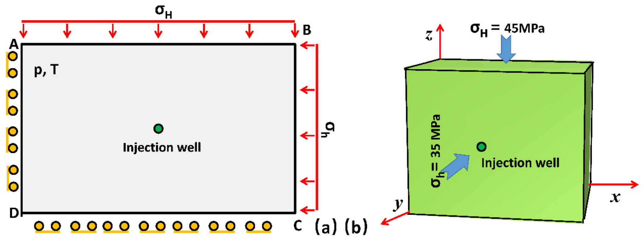
The following assumptions are adopted in the construction of the numerical model (Figure 1):
(1)
The reservoir rock is treated as a continuous, isotropic, and homogeneous porous medium.
(2)
The mechanical behavior is described by continuum damage mechanics, with failure governed by the maximum tensile stress criterion and the Mohr–Coulomb criterion.
(3)
Small-strain and small-displacement conditions apply, consistent with poroelasticity theory.
(4)
Fluid flow in the fractures and porous matrix obeys Darcy’s law.
(5)
Local thermal equilibrium is assumed between the fluid and the solid skeleton; heat transfer follows Fourier’s law.
(6)
No chemical reactions occur between the reservoir rock and the groundwater; the rock matrix is fully saturated with water.
(7)
The present model is a thermo-hydro-mechanical (THM) model. Molecular-scale interpretations (as hypotheses based on previous literature) are used only for discussion and are not formulated as governing equations.
The present model is two-dimensional, homogeneous, and isotropic. These simplifications differ significantly from real shale and granite reservoirs, which typically contain bedding planes, natural fractures, and spatial heterogeneity in mechanical and petrophysical properties. The idealized two-dimensional homogeneous isotropic framework was deliberately adopted to isolate the fundamental thermo-hydro-mechanical coupling mechanisms without the confounding effects of geological complexity. Consequently, the simulated fracture geometries and propagation patterns should be interpreted as baseline behaviors under simplified conditions. Extension of the model to three-dimensional heterogeneous media that incorporate bedding, discrete fracture networks, and property variability is recognized as an important direction for future research.

2.2. Mathematical Governing Equations

The coupled THM problem is governed by the following equations of energy conservation, mass conservation, linear momentum balance, and damage evolution.

2.2.1. Multiphase-Coupled Thermal Field

The local thermal equilibrium equation, thermal convection behavior, and strain energy are incorporated into the thermal field governing equations (Equation (1)) simultaneously in order to describe the thermal field distribution and thermal energy conversion between fluids and rocks in geological reservoirs [20,21].
( ρ c ) e q T t + ρ w c w v T = ( λ e q T ) + Q T
where ( ρ c ) e q is considered as the equivalent volumetric heat capacity, v is the Darcy velocity, λ e q is the equivalent thermal conductivity, Q T is the heat sources/sinks, and ρ w and c w are the fluid density and specific heat capacity of the fluid, respectively.
The left-hand side of Equation (1) is thus representative of the change in the system’s internal energy, the adjustment of thermal strain energy, convective heat transfer, and conductive heat transfer, while the right-hand side is representative of the internal heat source.

2.2.2. Reservoir Seepage Equation

The pores present in geological reservoirs determine the seepage behavior of fracturing fluids within the porous rock, a process that is also influenced by reservoir conditions and fluid characteristics. Equations (2) through (5) present the governing equations for the seepage field in geological reservoirs, which are also affected by the thermal state of the multiphase medium [22].
e 1 ε v t e 2 T t + e 3 p t = k μ p + ρ l g z
e 1 = K K s 1
e 2 = ϕ α l + 1 ϕ α s α T K K S
e 3 = ϕ β l + 1 ϕ K S
where ε v is the volumetric strain of multiphase reservoir rock containing fracturing fluid, K and K s are the drained bulk modulus and bulk modulus of reservoir rock, respectively, α l and α s are the volumetric thermal expansion coefficients of fracturing fluid and reservoir rock, respectively, β l is the bulk modulus of fracturing fluid, e1 is the time derivative term describes the effect of the change in volumetric strain (or sv) over time on the system’s storage capacity, e2 is additional pressure or volume change in fluids and solids resulting from differential thermal expansion, e3 is the combined storage coefficient accounting for the compressibility of fluids and solid particles in response to pressure changes (∂p/∂t), μ is the shear viscosity of fracturing fluid, and p is the pressure difference in the geological reservoir before and after fracturing.
Meanwhile, the left-hand side of the seepage equation presented in Equation (2) consists of time-dependent terms (storage term plus coupling term), which describe the mutual interactions among volumetric strain, temperature, and pressure. The right-hand side of the seepage equation represents the Darcy flow term (fluid mass conservation).

2.2.3. Stress Field Equation

The stress field equation for geological reservoirs is given by Equation (6). This primarily applies to linear elastic bodies where pore fluid pressure and temperature variations are taken into account [23].
σ + f = 0 ,     σ = 2 G ε +   λ ( · u ) I α p I 3 α T ( T T 0 ) I  
where G is the stress modulus, λ is the first lame parameter, α is the Biot coefficient, σ is the total stress tensor, f is the physical vector, I is the unit tensor, p is the pore pressure, K is the bulk modulus, α T is the linear thermal expansion coefficient, and T is the initial reference temperature.

2.2.4. Boundary Conditions and Reservoir Parameters

The boundary conditions of the numerical model can be calculated and solved according to Equation (7) [24].
σ i j x , y , z , t = 0 = σ v   σ H   σ h
where σ i j is stress tensor, and σ v ,   σ H ,   a n d   σ h are the vertical crustal stress, maximum horizontal principal stress, and horizontal minimum principal stress, respectively.
It should be noted that the initial state of a geological reservoir is defined by stress rather than strain, and that the stress state of the formation requires re-equilibration following drilling and cementing operations.
Relevant parameters for solid rock and fluids in the geological reservoir are presented in Table 1.
The parameters listed in Table 1 are primarily selected based on typical values reported for granite reservoirs in the literature. The thermal expansion coefficient (8.0 × 10⁻⁶/K), Young’s modulus (50 GPa), and Poisson’s ratio (0.25) fall within the commonly accepted ranges for granite under reservoir conditions. The initial permeability (5 × 10⁻¹⁵ m2) and porosity (0.01) are consistent with low-permeability tight formations. The coupling coefficient (0.07) used in the damage–permeability relationship and the permeability jump coefficient (ξ = 100 at full damage) follow the empirical values widely adopted in continuum damage mechanics models for rock fracturing. Although these values are representative, their influence on the simulation results is further examined through sensitivity analysis in Section 2.4. In addition, all parameters are representative values for granite under typical reservoir conditions, selected from the literature. Their influence has been examined through the sensitivity analysis in Section 2.4.
The boundary conditions are defined as follows:
Mechanical boundaries: the outer boundaries of the 2D domain are subjected to the in situ stress components σ v ,   σ H ,     a n d   σ h (Equation (7)). The wellbore boundary is traction-free or subjected to the fluid pressure during injection.
Hydraulic boundaries: a constant injection rate (or pressure) is prescribed at the perforation/wellbore; the far-field boundaries are set to the initial reservoir pressure.
Thermal boundaries: the injected fluid temperature is prescribed at the inlet; the far-field boundaries are maintained at the initial reservoir temperature, or adiabatic conditions are applied as appropriate.

2.2.5. Damage Evolution Equation for Reservoir Rocks

The application of the damage evolution equation presupposes that the reservoir rock is an isotropic, homogeneous material. Furthermore, the use of the damage variable D and its evolution to describe the initiation and propagation of internal fractures within the geological reservoir is based on the theory of continuum damage mechanics. The damage criteria follow the maximum tensile stress criterion (Equation (8)) and the Mohr–Coulomb criterion (Equation (9)), which are commonly adopted for brittle rock failure in continuum damage mechanics frameworks [25].
σ 1 = σ t
σ 1 σ 3 1 + sin θ 1 sin θ = 2 c cos θ 1 sin θ
where σ 1 and σ 3 are the maximum and minimum principal stresses, respectively, and σ t is the uniaxial tensile strength of the rock. When σ 1 reaches σ t , tensile failure occurs, and the damage variable begins to evolve. θ is the internal friction angle, and c is the cohesion.
Elastic damage theory provides a crucial theoretical basis for the elastic-brittle behavior exhibited by reservoir rocks at the microscopic level, with structural strength and the degree of damage being inversely related. Equation (10) illustrates the relationship between the elastic modulus (ED) of the reservoir rock and the damage variable (D) [26].
E D = 1 D E 0
where E0 is the initial modulus of elasticity. The damage variable D can take any value in the range of 0 to 1. D = 0 indicates that the reservoir rock is completely undamaged, while D = 1 signifies that the reservoir rock is fully fractured.
When tensile failure occurs in reservoir rock, the damage variable can be expressed by Equation (11).
D = 0 , ε < ε t 0 1 σ t r E 0 ε , ε t 0 < ε < ε t u 1 , ε t u ε
where σ t r is the residual tensile strength, and ε t 0 and ε t u are the tensile strain and maximum tensile strain at the elastic limit, respectively. ε t u ε is considered as the reservoir rock completely losing its bearing capacity.
Concurrently, Equations (12) and (13) illustrate how the permeability of reservoir rock is influenced by the effects of tensile and shear damage [27].
k D = k e β σ 3 α p , D = 0 ξ k e β σ 3 α p , 0 < D < 1 ξ k e β σ 3 α p , D = 1
k D = k e β σ 3 α p , D = 0 ξ k e β σ 3 α p , D > 0
where k D is the rock permeability after damage, β is the coupling coefficient (0.07) between two parameters, and ξ is the permeability jump coefficient. ξ = 5 when 0 < D < 1 . When the reservoir rock is completely fractured, ξ = 100.
The permeability post-damage is related to the damage variable D through a jump coefficient, designated as ξ. This coefficient accounts for the abrupt increase in permeability once damage accumulates and flow pathways become connected. In this study, the parameter known as ξ is assigned a value of 5 at the onset of significant damage (representing moderate permeability enhancement due to micro-crack coalescence) and a value of 100 when the rock is fully fractured (D = 1). The empirical values under consideration have been selected based on ranges that have been widely adopted in continuum damage mechanics models for brittle rock and in previous THM simulations of hydraulic fracturing in granite and low-permeability formations. The lower value (ξ ≈ 5) corresponds to the initial permeability increase that was observed during the early damage stage, while the upper value (ξ = 100) reflects the sharp, orders-of-magnitude permeability jump that occurs when a macroscopic fracture network is fully developed. This is consistent with laboratory observations of fracture permeability in crystalline rocks. Despite the fact that the coefficients are not derived from site-specific experiments in the present work, they are consistent with the ranges reported in the literature. The influence of the fully-damaged jump coefficient was further examined by varying the parameter ξ between 50 and 200. The resulting changes in fracture length remained within ± 8%, indicating that the primary conclusions are robust within the commonly used empirical range.

2.2.6. Calculation of Seepage, Imbibition, Adsorption, and Proppant Settling

Seepage volume is calculated by integrating the normal component of the Darcy velocity (Equation (14)) over the fracture surfaces and accumulating the flux with respect to time:
V seepage ( t ) = 0 t Γ f v · n d Γ d τ  
where v is the Darcy velocity, Γ f denotes the fracture boundary, n is the external normal unit vector of crack surface, and d Γ is the surface area of crack.
Imbibition volume is evaluated as the cumulative fluid mass that enters the porous matrix from the fracture faces, obtained from the difference between the injected volume and the fluid remaining inside the fracture aperture.
Adsorption amount is estimated for interpretive purposes using a simplified Langmuir-type expression (Equation (15)) relating polymer adsorption to local concentration and specific surface area of the fracture walls. This quantity is not solved as an independent field, but is post-processed to support the molecular-scale discussion.
q = q max K C 1 + K C  
where q is the adsorption capacity, qmax is the max adsorption capacity, K is the adsorption equilibrium constant, and C is the polymer concentration.
Proppant settling velocity is computed from Stokes’ law (Equation (16)).
v = 2 9 r 2 ( ρ ρ 0 ) g η  
where r and ρ are the proppant particle radius and density, respectively, ρ 0 and η are the fracturing fluid density and viscosity, respectively, and g is the gravitational acceleration.

2.2.7. Numerical Implementation and Computational Details

The fully coupled THM equations were solved using the finite element method (FEM) implemented in COMSOL Multiphysics 6.3.
  • Model geometry and mesh
The computational domain is a two-dimensional square (or rectangle) with dimensions of 100 m × 100 m. The wellbore/perforation is located at the center. The domain was discretized with quadrilateral elements. The mesh consists of approximately 42,800 quadrilateral elements, with a refined element size of Δh = 0.10 m near the fracture path and a coarser size of ΔH = 2.0 m in the far field. Mesh sensitivity analysis confirmed that further refinement changed fracture length by less than 2%.
  • Time stepping and convergence
An adaptive (or fixed) time-stepping scheme was employed, with an initial time step of Δt0 = 0.01 s and a maximum time step of Δtmax = 10 s. The total simulation time is 1800 s. Convergence was controlled by a relative residual tolerance of 10−6 for the coupled system.
  • Injection conditions
Fluid was injected at a constant rate of 10 m3/min at the wellbore/perforation. The injected fluid temperature was set to 35 °C.
  • Boundary and initial conditions
Mechanical: far-field boundaries are subjected to in situ stresses σ v = 50 MPa, σ H = 45 MPa, and σ h = 35 MPa. The wellbore is traction-free or pressurized by the fluid pressure.
Hydraulic: far-field pore pressure is fixed at the initial reservoir pressure p0 = 25 MPa; no-flow or constant-pressure conditions are applied as appropriate.
Thermal: far-field temperature is fixed at the initial reservoir temperature T0 = 90 °C; the injection boundary is set to Tinj = 25 °C.
Initial conditions: uniform initial stress, pore pressure and temperature fields corresponding to the undisturbed reservoir state.

2.3. Thermo-Hydro-Mechanical Coupling in Water-Based Hydraulic Fracturing of Geological Reservoirs

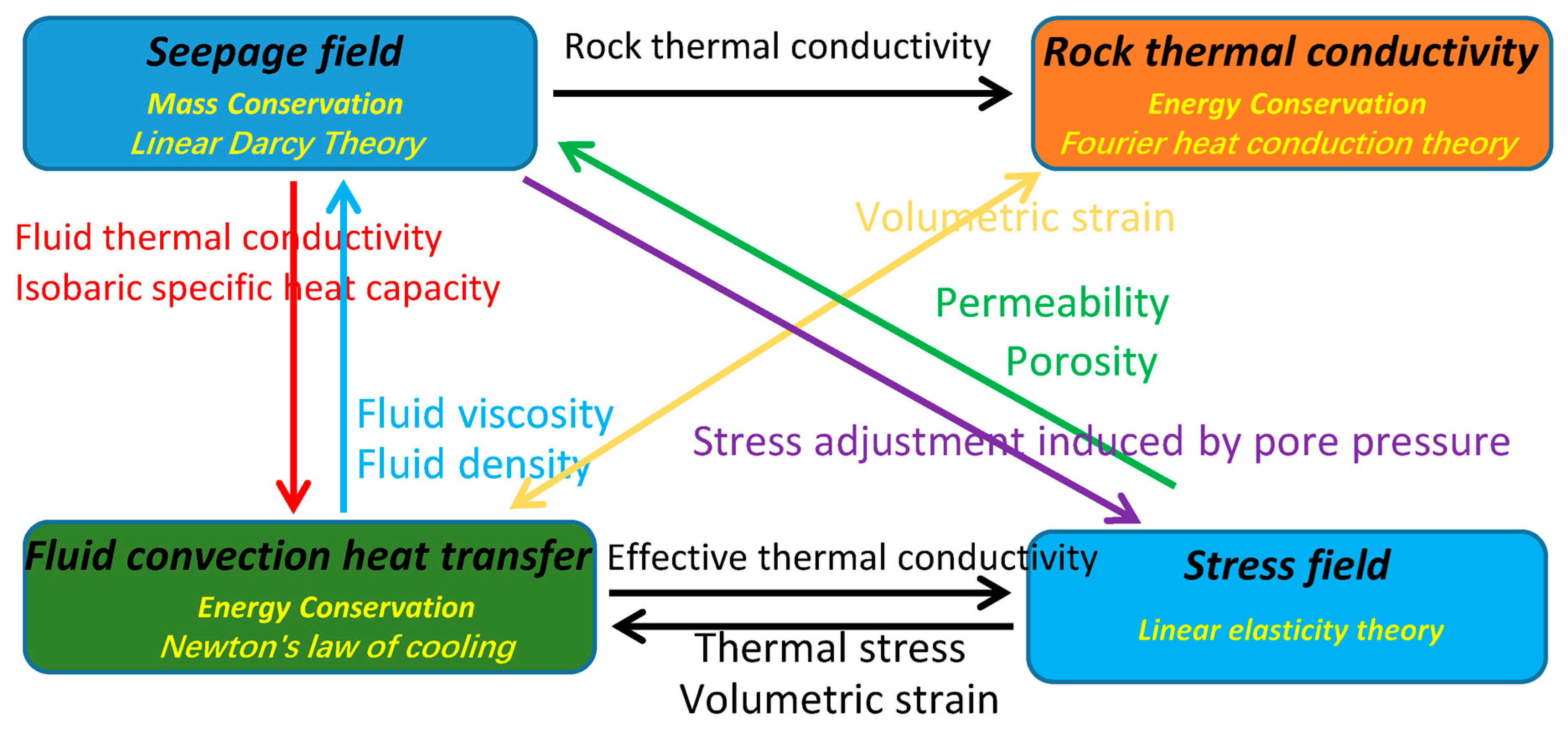
In water-based hydraulic fracturing within geological reservoirs, the thermal, hydraulic, and mechanical fields are tightly coupled and jointly control fracture initiation, propagation, and sustained conductivity. High-pressure fluid injection establishes the seepage field, which alters the mechanical response of the rock through poroelastic effects and effective stress reduction, thereby facilitating tensile or shear failure. At the same time, temperature contrasts between the cooler injected fluid and the warmer formation generate thermal stresses that modify fluid viscosity and rock mechanical properties, influencing both fracture aperture and growth behavior. Although molecular-scale interactions (such as hydrogen bond network evolution and polymer adsorption) are invoked in later sections as hypotheses based on previous literature to offer possible interpretations of the macroscopic fluid behavior and leak-off characteristics. These processes are not formulated as an independent chemical field with governing equations, nor are they supported by molecular simulations or new experimental measurements performed in this study. No reactive transport, mineral dissolution/precipitation, or chemical concentration equations are solved. The framework is therefore strictly a continuum-scale thermo-hydro-mechanical (THM) model. The framework is therefore a thermo-hydro-mechanical (THM) model. This THM coupling is essential for capturing the bidirectional interactions among fluid flow, heat transfer, and rock deformation and for reliably predicting fracturing performance under the conditions examined in this study (Figure 2).

2.4. Sensitivity Analysis of Key Parameters

To evaluate the robustness of the numerical model and the influence of key input parameters, a systematic sensitivity analysis was conducted of three critical parameters: initial permeability, thermal expansion coefficient, and the damage–permeability coupling coefficient (Table 2). Each parameter was varied within a physically reasonable range while keeping other conditions constant. The primary response variables examined were fracture length, fluid leak-off volume, and net fracture pressure.
Initial permeability: Values of 1 × 10⁻¹⁵, 5 × 10⁻¹⁵ (base case), and 1 × 10⁻¹⁴ m2 were tested. Higher permeability significantly increased fluid leak-off and reduced fracture length, confirming that permeability strongly controls pressure retention within the fracture.
Thermal expansion coefficient: Values of 5.0 × 10⁻⁶, 8.0 × 10⁻⁶ (base case), and 1.2 × 10⁻⁵/K were examined. Larger thermal expansion coefficients amplified thermal stress effects, moderately promoting fracture extension under cold fluid injection conditions.
Coupling coefficient: The coefficient in the damage–permeability relationship was varied from 0.05 to 0.10 (base case 0.07). The results showed that higher coupling coefficients accelerated permeability enhancement after damage initiation, leading to slightly longer fractures but increased leak-off in the later propagation stage. In addition, the fully damaged permeability jump coefficient ξ was varied between 50 and 200. Fracture length changed by less than ± 8%, confirming that the main propagation trends are not highly sensitive to the precise value of ξ within the typical empirical range.

2.5. Model Validation

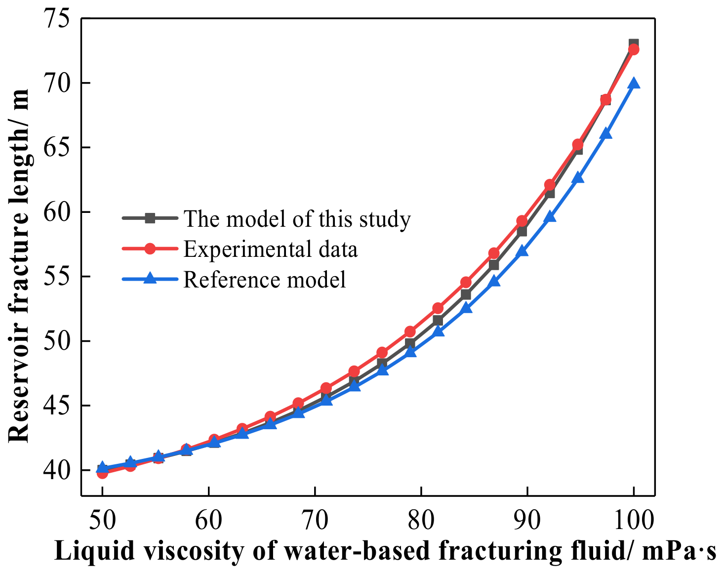
To evaluate the reliability and predictive capability of the proposed THM coupling model, quantitative validation was performed by comparing the simulation results with the independent numerical results reported by Zhang et al. (2025) [28] (Figure 3) and available experimental measurements under equivalent reservoir and operational conditions. Three critical hydraulic fracturing responses were selected for validation, including breakdown pressure, fracture half-length evolution, and fracture aperture evolution.
The relative error (Equation (17)) between the simulated and reference results was calculated using
E r r o r ( % ) = X mod e l X r e f X r e f × 100 %
where X mod e l and X r e f are the model data and reference data, respectively.
As shown in Table 3a, the breakdown pressure predicted by the present model was 33.7 MPa, which is close to the value of 32.0 MPa reported by Zhang et al. (2025) [28] and the experimental measurement of 33.9 MPa. The relative error between the present model and the reference numerical result was calculated as 5.3%, indicating good agreement in predicting fracture initiation pressure.
The fracture propagation capability was further evaluated by comparing the evolution of fracture half-length during the injection process. The coefficient of determination (R2) (Equation (18)) was introduced to quantify the consistency between the simulated and reference fracture propagation trends:
R 2 = 1 i = 1 n ( Y i Y i Λ ) 2 i = 1 n ( Y i Y ) 2
where Yi and Y i Λ are the reference data and model prediction values, respectively, and Y and n are the average of the reference data and the number of data points, respectively.
As presented in Table 3b, the predicted fracture half-length evolution agrees well with both Zhang et al. (2025) [28] and the experimental results over the entire injection period. The calculated (R2) value between the present model and the reference data is 0.94, demonstrating that the proposed model can accurately reproduce the fracture propagation behavior.
Furthermore, fracture aperture evolution was evaluated to verify the capability of the model in predicting fracture geometry. The average relative error (Equation (19)) was calculated as
E r r o r a v g ( % ) = 1 n i = 1 n X mod e l , i X r e f , i X r e f , i × 100 %
where X mod e l , i is the calculated value of the i-th model, and X r e f , i is the i-th reference value.
According to Table 3c, the predicted fracture aperture evolution follows the same trend as the reference results, with an average deviation of approximately 3.2%. This confirms that the proposed model can reasonably capture not only fracture initiation and propagation, but also fracture opening characteristics. Overall, the validation results demonstrate that the proposed THM coupling model provides reliable predictions of key hydraulic fracturing responses, including breakdown pressure, fracture extension, and aperture evolution. Although direct laboratory-scale validation under fully coupled thermal–hydraulic–mechanical conditions remains challenging due to the limited availability of comprehensive datasets, the agreement with independent numerical benchmarks and experimental observations provides sufficient confidence in the applicability of the developed model.

3. Results and Discussion

Numerical simulations of hydraulic fracturing in geological reservoirs provided detailed insights into the coupled hydro-mechanical processes governing fracture initiation, propagation, and interaction with the surrounding formation. The developed model effectively reproduced the complex evolution of fracture networks, capturing the interplay among fluid injection, in situ stress conditions, and reservoir heterogeneity that dictates fracture geometry and connectivity [29,30]. Simulated pressure distributions and displacement fields highlighted localized stress perturbations and fluid leak-off patterns, revealing the dominant mechanisms controlling stimulated reservoir volume and fracture conductivity [31]. These results demonstrate the substantial influence of geomechanical and hydraulic parameters on overall fracturing performance, offering a robust basis for interpreting field-scale observations and refining engineering strategies for optimized reservoir stimulation [32,33]. It should be noted that the trends presented in Figure 4, Figure 5, Figure 6, Figure 7, Figure 8, Figure 9, Figure 10 and Figure 11 are obtained from deterministic numerical simulations. Therefore, classical statistical error bars derived from repeated experimental measurements are not applicable. The robustness of the main qualitative trends in response to variations in key input parameters has been examined through the sensitivity analysis reported in Section 2.4.

3.1. Fracture Geometry and Propagation Behavior

3.1.1. Adjustment of Fracture Propagation and Geometry by Fluid Viscosity

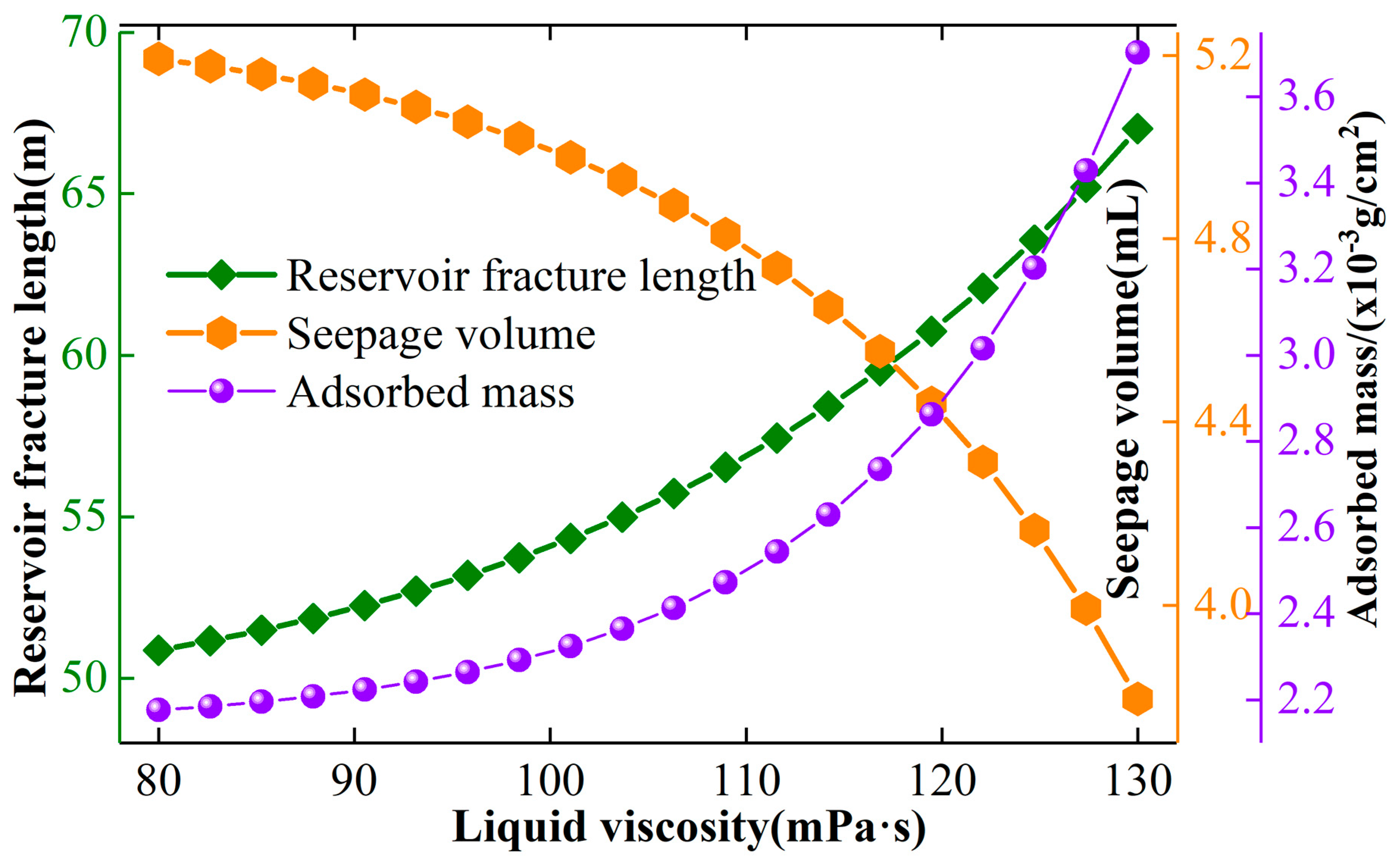
The evolution of fracture geometry and propagation behavior is strongly influenced by the rheological properties of the fracturing fluid, among which fluid viscosity is one of the primary factors controlling fracture growth and stimulation effectiveness [34,35]. To quantify this effect, the relationships among fluid viscosity, fracture propagation, and fracture morphology were systematically investigated. Figure 4 presents the variation trends in fracture length, seepage volume, and adsorption amount in response to different fluid viscosities. The fracture length values shown in Figure 4 correspond to the numerical results obtained from the present THM coupling model. Table 4 further provides the detailed quantitative fracture length values and compares them with those reported by previous numerical studies. Therefore, Figure 4 and Table 4 describe the same viscosity-dependent fracture propagation behavior from different perspectives: Figure 4 emphasizes the overall trend, whereas Table 4 provides specific numerical comparisons for model evaluation. This behavior can be attributed to the enhanced capability of high-viscosity fluids to maintain fracture pressure, thereby facilitating crack opening and propagation under in situ stress conditions [36,37]. The comparison with published data demonstrates that the proposed model successfully reproduces the overall trend of viscosity-dependent fracture growth [38]. Although the predicted fracture lengths are slightly lower than those reported in previous studies at comparable viscosities [39], the discrepancy is primarily attributed to the improved physical representation and enhanced numerical formulation incorporated into the present THM coupled model, which enables a more realistic characterization of the coupled thermal–hydraulic–mechanical–chemical processes governing hydraulic fracture propagation (Table 4).
Figure 4. Changes in fracture length, seepage volume, and adsorption amount (calculated as described in Section 2.2.6) in response to varying fluid viscosities. (Deterministic numerical results; see Section 2.4 for parameter sensitivity.).
Processes 14 02923 g004
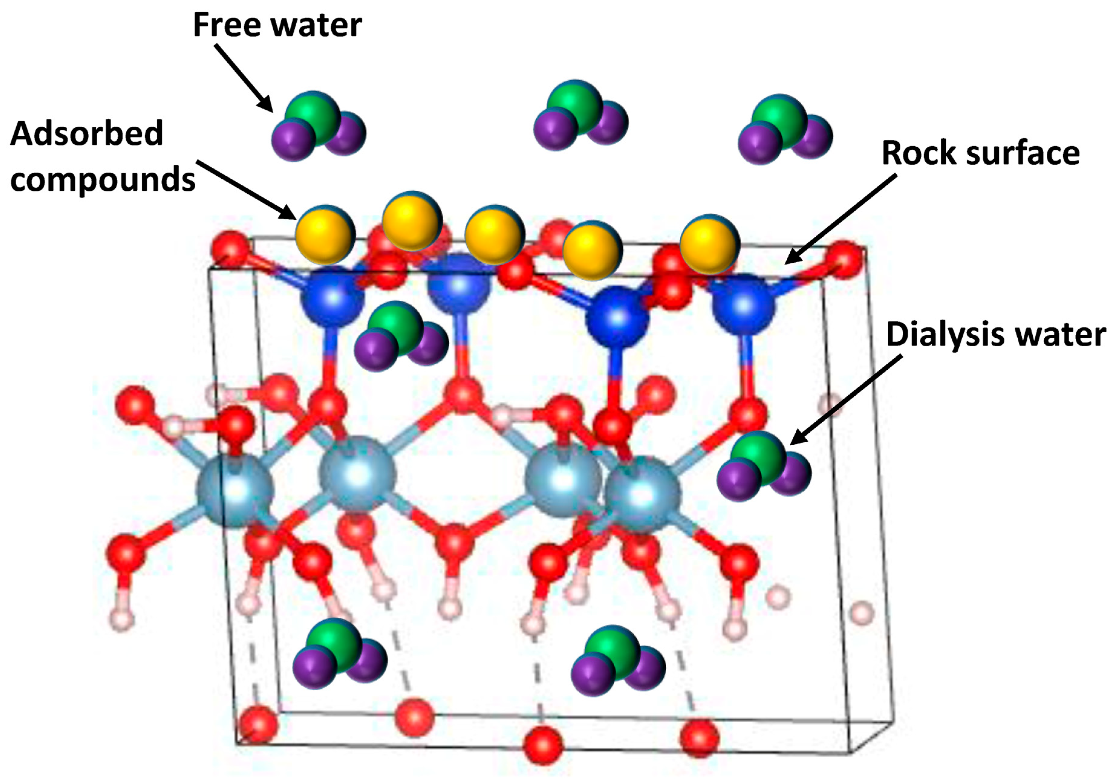
Drawing upon the extant literature concerning intermolecular interactions in polymer aqueous solutions and previous research on reservoir fracturing, we offer the following molecular-scale discussion as a hypothesis that may provide a possible mechanistic explanation for the macroscopic trends observed in the continuum-scale simulations [40]. It must be emphasized that these interpretations are not supported by molecular dynamics simulations or new experimental data obtained in the present work [41,42]. The enhanced rock-fracturing capability associated with high-viscosity fluids may be interpreted, consistent with previous studies, from a molecular-scale perspective. In particular, intermolecular interactions, especially hydrogen bonding and van der Waals forces, have been widely reported to play a fundamental role [43,44,45]. In particular, intermolecular interactions, especially hydrogen bonding and van der Waals forces, play a fundamental role in determining the rheological properties of fracturing fluids and consequently influence fracture propagation behavior [46,47]. Previous studies [48] have shown that the elevated macroscopic viscosity of water-based fracturing fluids can be interpreted as arising from the formation of an interconnected molecular network mediated by hydrogen bonds between water molecules and polymeric additives. The density and stability of this hydrogen bond network are widely regarded as key factors that govern the fluid viscosity and structural integrity [49,50]. When the hydrogen bond density is low, the molecular network becomes insufficiently developed to bind the fluid into a cohesive gel structure, resulting in a larger fraction of free water molecules [51,52]. These unbound molecules can more readily penetrate the porous reservoir matrix, thereby increasing fluid leak-off and reducing the pressure retained within the hydraulic fracture at a given injection rate (Figure 5). According to fracture mechanics and damage evolution theory, fracture propagation occurs only when the fluid pressure inside the fracture exceeds the effective in situ stress acting on the surrounding rock [53]. Therefore, the lower fracture pressure associated with low-viscosity fluids is less effective in initiating and propagating hydraulic fractures, resulting in reduced rock damage and a smaller stimulated reservoir volume. In contrast, high-viscosity fracturing fluids promote the formation of dense and stable intermolecular networks through enhanced hydrogen bonding and van der Waals interactions, thereby incorporating a greater fraction of water molecules into a cohesive gel-like structure [54,55]. The resulting reduction in molecular mobility can effectively suppress fluid leak-off into the surrounding rock matrix, allowing a larger proportion of the injected fluid pressure to be retained within the hydraulic fracture [56,57]. Consequently, the elevated fracture pressure can more readily overcome the effective in situ stress, thereby promoting fracture initiation and propagation and facilitating the development of more extensive fracture networks [47,58]. Overall, fluid viscosity governs hydraulic fracture propagation primarily by regulating fluid leak-off and fracture pressure evolution [59]. Higher-viscosity fluids reduce pressure dissipation, sustain higher net fracture pressures, and thereby create more favorable conditions for continued fracture propagation and enhanced reservoir stimulation.
Figure 5. Adsorption and water imbibition behavior of water and compounds from fracturing fluid within reservoir fractures. (Deterministic numerical results; see Section 2.4 for parameter sensitivity.).
Processes 14 02923 g005
Furthermore, polymeric additives and crosslinking agents in water-based fracturing fluids can adsorb onto fracture surfaces and pore walls within the reservoir rock, thereby altering the fluid–rock interfacial properties and reducing fluid leak-off into the surrounding formation [60]. Low-viscosity fracturing fluids generally contain lower concentrations of these functional additives, resulting in relatively weak adsorption on the rock surface [61,62]. Consequently, the pore throats and microfractures remain largely unobstructed, allowing a greater proportion of free water molecules to penetrate the rock matrix [63]. This enhanced fluid leak-off is consistent with the inverse relationship between adsorption capacity and seepage volume observed in Figure 4. The increased fluid leak-off associated with low-viscosity fluids accelerates pressure dissipation within the hydraulic fracture, thereby reducing the net fracture pressure available to overcome the effective in situ stress and limiting fracture propagation [64,65]. In contrast, high-viscosity fracturing fluids typically contain higher concentrations of polymers and crosslinking agents, which promote stronger adsorption on fracture surfaces and pore walls [66,67]. The adsorbed polymer layer partially blocks pore throats and microfractures, reducing the effective permeability of the near-fracture region and suppressing fluid leak-off. As a result, a larger proportion of the injected fluid pressure is retained within the fracture, facilitating fracture opening, propagation, and the development of more complex fracture networks [68]. Therefore, the enhanced fracturing performance of high-viscosity fluids arises not only from the formation of a stable intermolecular network that improves fluid rheological properties, but also from the adsorption-induced reduction in fluid leak-off [69]. Together, these mechanisms maintain higher net fracture pressures, thereby promoting more effective fracture propagation and reservoir stimulation.

3.1.2. Effect of Rock Porosity on Fluid Permeation and Fracture Propagation
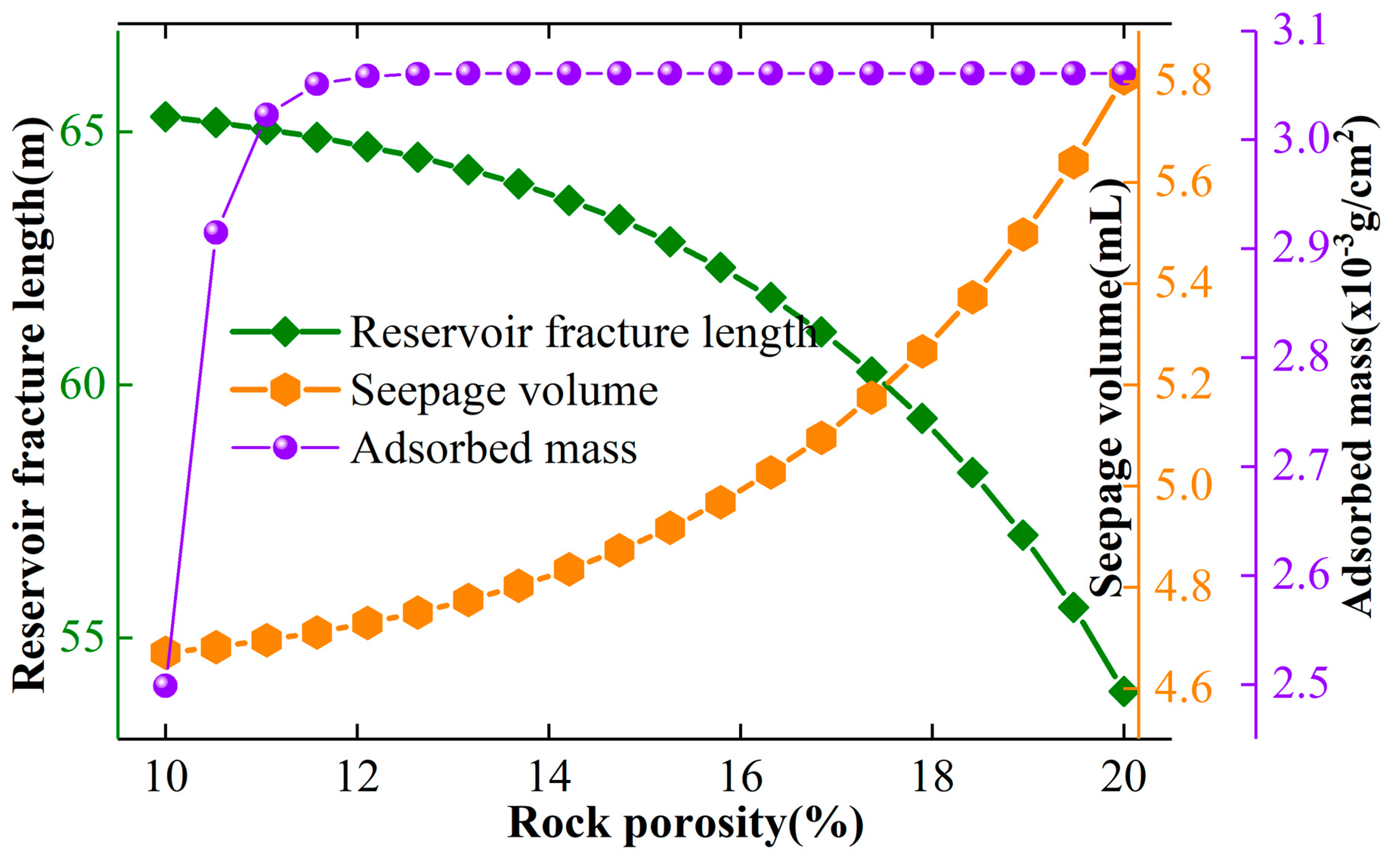
Reservoir porosity is a fundamental petrophysical property that strongly influences both hydraulic fracture propagation and the transport behavior of water-based fracturing fluids. To evaluate its effect, fracture propagation and fluid leak-off were systematically investigated under different reservoir porosity conditions. Figure 6 presents the corresponding variations in fracture length and fluid leak-off volume as a function of reservoir porosity. As shown in Figure 6, fracture propagation exhibits a clear negative correlation with reservoir porosity. Increasing porosity suppresses fracture growth, resulting in lower fracture propagation rates and shorter final fracture lengths. In contrast, low-porosity formations exhibit more favorable fracture propagation behavior, as evidenced by a slower decline in fracture growth rate and greater fracture extension during the injection process. These results indicate that reservoir porosity plays a critical role in controlling fracture growth dynamics and should therefore be considered when predicting hydraulic fracture propagation in different geological formations. Figure 6 also demonstrates a positive correlation between reservoir porosity and fluid leak-off. Reservoirs with low porosity exhibit relatively limited fluid leak-off because of the restricted pore space available for fluid migration, whereas highly porous formations provide abundant flow pathways that facilitate the infiltration of fracturing fluid into the surrounding rock matrix. Consequently, fluid leak-off increases significantly with increasing porosity. These findings suggest that reservoir porosity simultaneously governs fracture propagation and fluid transport behavior, providing important guidance for predicting leak-off characteristics and optimizing hydraulic fracturing operations under different reservoir conditions.
The observed negative correlation between reservoir porosity and fracture propagation can be interpreted from the perspectives of fluid leak-off and pressure evolution at the pore scale. In low-porosity formations [70], the fracture surfaces contain relatively few pore throats and microfractures. The limited pore space can be more effectively modified by the adsorption of polymeric additives and crosslinking agents contained in the fracturing fluid [71,72], thereby reducing fluid leak-off into the surrounding rock matrix. Consequently, a greater proportion of the injected fluid pressure is retained within the hydraulic fracture, enabling the fracture pressure to more rapidly exceed the effective in situ stress required for fracture initiation and propagation [73,74,75]. In contrast, high-porosity reservoirs possess a larger number of interconnected pore throats and microfractures, providing abundant pathways for fluid migration into the surrounding formation [76]. Although chemical additives adsorb onto the rock surface, the adsorption layer is insufficient to effectively reduce fluid leak-off throughout the extensive pore network [77]. As a result, increased fluid leak-off accelerates pressure dissipation within the fracture, reducing the net fracture pressure available for fracture extension [78]. Consequently, fracture propagation is suppressed, leading to slower fracture growth and a less extensive stimulated reservoir volume [79]. These results indicate that reservoir porosity influences fracture propagation primarily through its control of fluid leak-off and fracture pressure evolution [80]. Excessively high porosity promotes pressure dissipation within the fracture, thereby reducing the hydraulic driving force required for sustained fracture propagation [81].
Figure 6. Curves showing the influence of rock porosity on fracture propagation, rock adsorption, and fluid imbibition. (Deterministic numerical results; see Section 2.4 for parameter sensitivity.).
Processes 14 02923 g006

3.1.3. Effect of Crack Deflection Angle
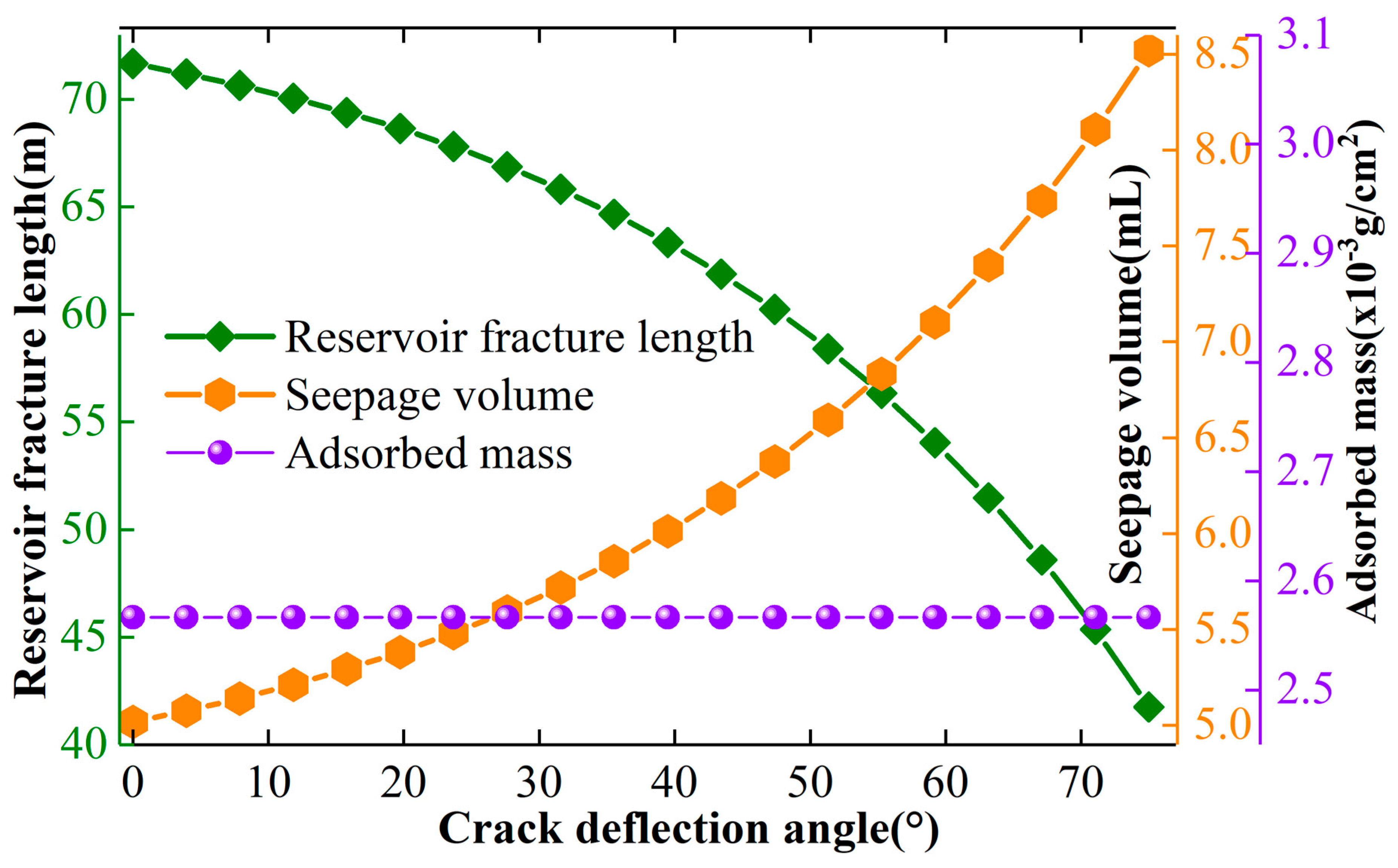
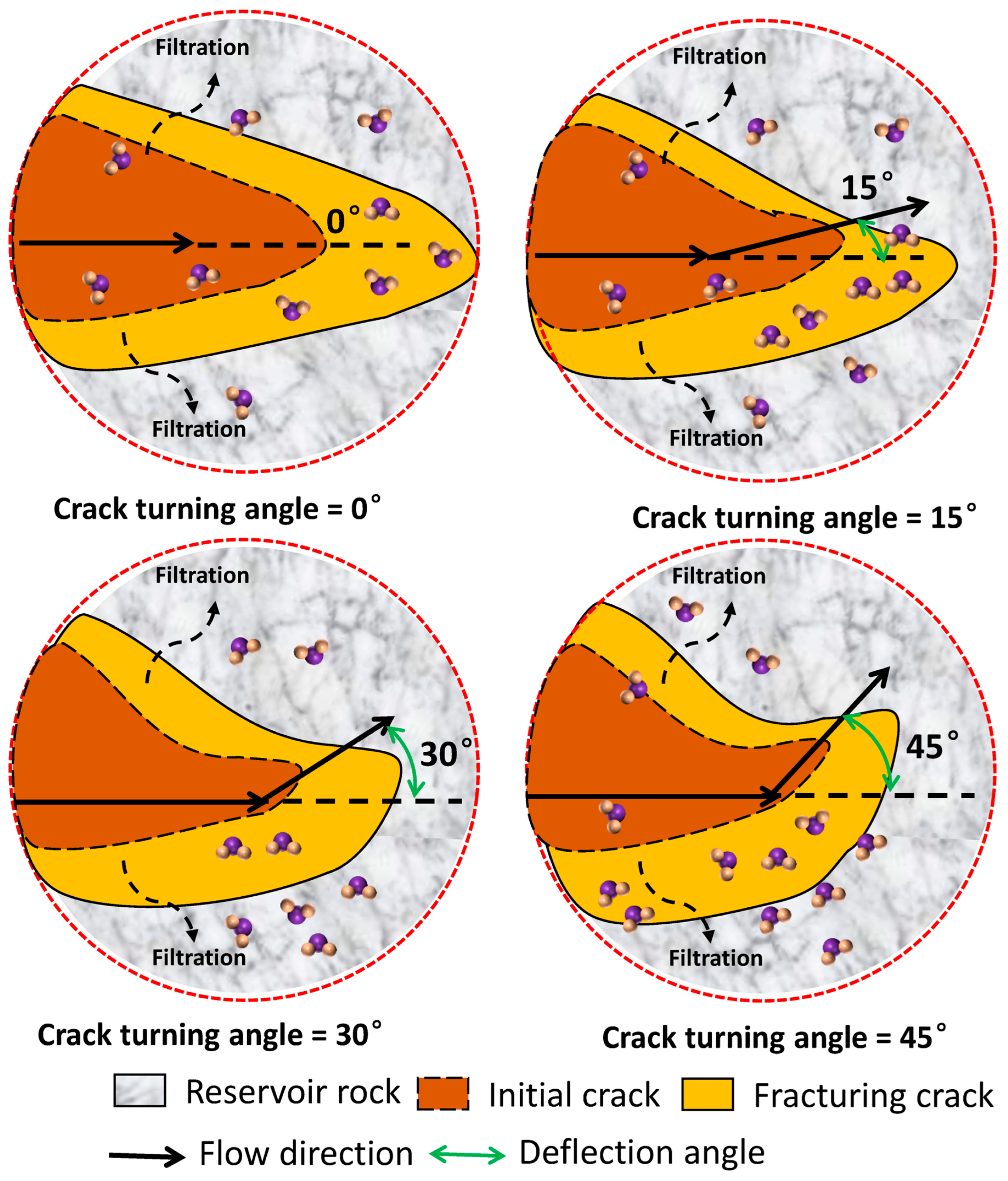
The fracture deflection angle is an important geometric parameter governing hydraulic fracture propagation, significantly influencing fluid transport behavior and the effectiveness of reservoir stimulation [82]. To quantify its effect, the relationships among fracture deflection angle, fracture propagation, and fluid leak-off were systematically investigated. Figure 7 presents the variations in fracture length and fluid leak-off volume under different fracture deflection angles. As shown in Figure 7, fracture propagation decreases progressively with increasing fracture deflection angle within the range examined in this study. Larger deflection angles suppress fracture growth and increase fluid leak-off, thereby reducing the effectiveness of reservoir stimulation under the present simulation conditions. When the fracture deflection angle is small, fracture growth remains largely unaffected, and only limited changes in fracture length and fluid leak-off are observed [83]. Beyond a certain angle, the normal flow component becomes significant, fracture propagation decreases markedly, and fluid leak-off increases rapidly [84]. These observations indicate that, within the limited set of deflection angles and fixed secondary parameters investigated here, smaller deflection angles are more favorable for sustaining fracture extension [85].
Figure 7. Influence of the fracture deflection angle on reservoir fractures, stimulated reservoir volume, and adsorption behavior (within the simulated range of angles). (Deterministic numerical results; see Section 2.4 for parameter sensitivity.).
Processes 14 02923 g007
No claim is made that any specific angle (including 45°) is universally optimal. Systematic multi-parameter optimization that simultaneously varies deflection angle together with fluid viscosity, porosity, in situ stress difference, and other factors was not performed and remains an important direction for future work. Consequently, excessive fracture deflection weakens the hydraulic driving force for fracture propagation under the conditions of this study, leading to less effective reservoir stimulation. We also investigated adsorption behavior on the rock surface; the relationship between the deflection angle and the amount of adsorption is represented by a nearly constant horizontal line.
The inhibitory effect of fracture deflection on fracture propagation can be primarily attributed to the evolution of fluid leak-off and fracture pressure induced by changes in flow direction (Figure 8). For a straight hydraulic fracture without deflection, the injected fracturing fluid flows predominantly parallel to the fracture surfaces, resulting in a negligible normal flow component and consequently limited fluid leak-off into the surrounding rock matrix [86]. Under these conditions, most of the injected fluid pressure is retained within the fracture, providing sufficient net fracture pressure to sustain fracture propagation [87]. As the fracture deflection angle increases, the normal component of the fluid flow relative to the fracture surfaces also increases, enhancing fluid penetration into the surrounding porous rock. For example, at a deflection angle of 30°, the increased normal flow component substantially promotes fluid leak-off compared with the non-deflected case [88]. A further increase in the deflection angle intensifies this effect, accelerating pressure dissipation within the hydraulic fracture and reducing the net fracture pressure available for fracture opening and propagation [89]. Consequently, larger fracture deflection angles lead to greater fluid leak-off, weaker hydraulic driving forces, and reduced fracture propagation efficiency [90]. These results demonstrate that the fracture deflection angle regulates hydraulic fracture growth primarily by controlling the balance between fluid leak-off and pressure retention within the fracture. Excessive fracture deflection promotes pressure dissipation, thereby suppressing fracture propagation under the conditions examined in this study [91]. The present findings are restricted to the simulated range of angles and do not constitute a verification of optimality under combined variations of multiple parameters.
Figure 8. Changes in crack morphology and fluid permeation under different deflection angles. (Deterministic numerical results; see Section 2.4 for parameter sensitivity.).
Processes 14 02923 g008

3.1.4. Effect of Reservoir Conditions

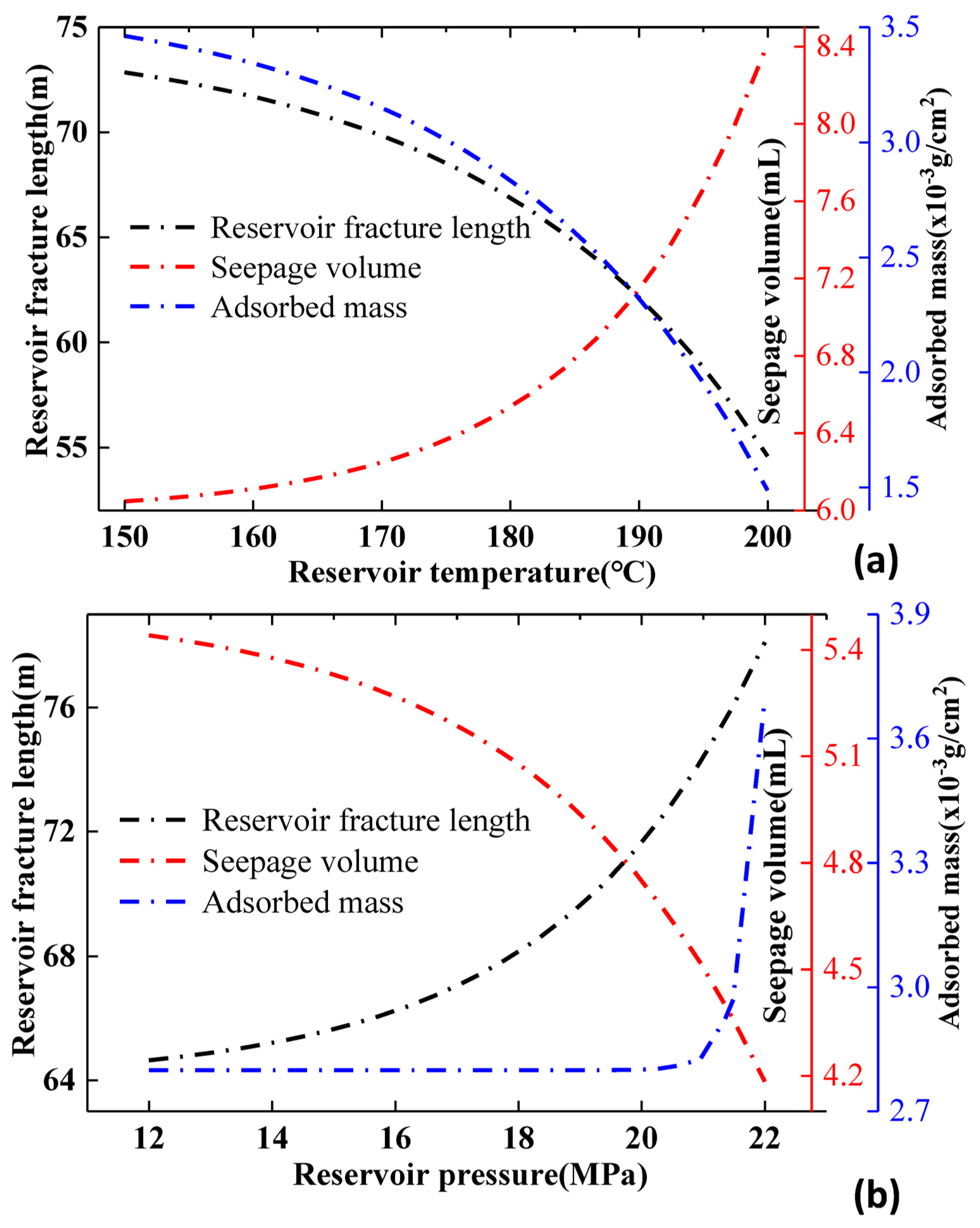
Reservoir temperature and pressure are two key geological parameters governing hydraulic fracture propagation, thereby exerting a significant influence on fracture length, fluid leak-off, and fracturing fluid sweep area under the conditions examined in this study. To evaluate their effects, fracture propagation and fluid leak-off were systematically investigated at different reservoir temperatures and pressures. Figure 9 presents the corresponding variations in fracture length and fluid leak-off volume under different reservoir conditions [92]. As shown in Figure 9, fracture propagation exhibits contrasting responses to reservoir temperature and pressure. Increasing reservoir temperature progressively suppresses fracture growth, leading to a continuous reduction in fracture length, with the rate of reduction becoming more pronounced at elevated temperatures. In contrast, increasing reservoir pressure facilitates fracture propagation, resulting in greater fracture extension and higher fracture growth rates. These results indicate that elevated reservoir pressure provides more favorable conditions for fracture development, whereas high temperatures inhibit fracture propagation. The fracture propagation responses to both reservoir temperature and pressure can be broadly divided into two stages: an initial stage characterized by relatively moderate variations, followed by a stage of accelerated change under more extreme reservoir conditions. At relatively low temperatures or pressures, fracture length changes gradually because the thermo-mechanical and hydraulic responses of the reservoir remain limited. As reservoir temperature or pressure continues to increase, the coupled thermo-hydraulic processes become increasingly pronounced, leading to more substantial changes in fracture pressure evolution and consequently altering fracture propagation behavior. These findings demonstrate that reservoir temperature and pressure jointly regulate hydraulic fracture growth through their influence on the coupled thermo-hydraulic response of the reservoir. Furthermore, the variation in fluid leak-off exhibits a trend opposite to that of fracture propagation [93]. Specifically, fluid leak-off increases with increasing reservoir temperature but decreases as reservoir pressure rises. Similar to the fracture propagation response, the leak-off behavior can also be divided into two distinct stages: an initial stage characterized by relatively moderate variations, followed by a stage of accelerated change under elevated reservoir temperatures or pressures [94]. At relatively low temperatures or pressures, changes in fluid leak-off remain limited, indicating that the coupled thermo-hydraulic response of the reservoir is relatively weak. In contrast, elevated temperatures or pressures substantially alter fluid transport behavior, resulting in rapid changes in fluid leak-off. The corresponding evolution of leak-off directly affects fracture pressure retention and consequently exerts a significant influence on hydraulic fracture propagation [95]. It should be noted that, although increasing temperature intensifies thermo-hydraulic interactions within the reservoir, the net effect under the present simulation conditions is inhibitory because the increase in fluid leak-off and pressure dissipation dominates over any potential thermal stress enhancement.
The Arrhenius relationship provides a theoretical framework for interpreting how temperature-dependent molecular processes in water-based fracturing fluids influence hydraulic fracture propagation [96], thereby linking microscopic molecular interactions with the macroscopic rheological properties of the fluid under different reservoir conditions [97]. According to the Arrhenius relationship, increasing reservoir temperature is expected to enhances molecular kinetic activity by supplying additional thermal energy to the fluid molecules [98]. This thermally activated molecular motion plays a fundamental role in regulating the evolution of the intermolecular network that governs the fluid’s macroscopic properties (Equation (20)) [99,100].
k m = A v exp (   E f R g T   )                        
where k m is the rate constants for molecular motion in water-based fracturing fluids, A v is the pre-exponential factor, E f is the activation energy of each molecule, R g is the gas constant (8.314 J·mol−1·K−1), and T is the absolute temperature. The negative exponent is required by the standard Arrhenius relation.
Previous studies have demonstrated that key characteristics of water-based fracturing fluids, including viscosity, fluid leak-off behavior, and proppant-carrying capacity, are primarily controlled by the intermolecular network formed through hydrogen bonding and other intermolecular interactions [101]. The density and stability of this network are highly sensitive to molecular mobility. At relatively low temperatures, molecular kinetic activity remains limited, resulting in reduced molecular mobility and weaker Brownian motion [102]. Consequently, the intermolecular network experiences only minor structural rearrangement, allowing hydrogen bonds and other intermolecular interactions to remain relatively stable and thereby maintaining the structural integrity and rheological properties of the fracturing fluid [103,104]. Furthermore, the limited molecular mobility at low temperatures suppresses large-scale molecular rearrangement, thereby reducing the probability of hydrogen bond dissociation and preserving the stability of the intermolecular network [105]. As a result, both the density and structural integrity of the hydrogen bond network remain largely unchanged, maintaining a stable three-dimensional gel structure that effectively constrains the mobility of water molecules within the fluid [106]. Because fluid leak-off primarily occurs through the migration of mobile water molecules into pore throats and microfractures within the surrounding rock matrix, the restricted molecular mobility associated with a stable intermolecular network substantially reduces fluid leak-off [107,108]. Consequently, the reduced pressure dissipation enables a greater proportion of the injected fluid pressure to be retained within the hydraulic fracture, maintaining a higher net fracture pressure that promotes sustained fracture propagation and greater fracture extension [109,110]. In contrast, elevated temperatures substantially enhance the kinetic activity of fluid molecules, intensifying Brownian motion and increasing the frequency of molecular collisions. Such thermally induced molecular rearrangement may destabilizes the hydrogen bond network and promotes the dissociation of intermolecular interactions, thereby reducing the structural integrity of the three-dimensional gel network [111]. Consequently, a greater proportion of water molecules becomes mobile, facilitating their migration into the surrounding rock matrix through pore throats and microfractures [112]. The increased fluid leak-off accelerates pressure dissipation within the hydraulic fracture, reducing the net fracture pressure available to overcome the effective in situ stress [113]. As a result, the hydraulic driving force for fracture extension is weakened, leading to slower fracture propagation and reduced reservoir stimulation efficiency.
Figure 9. Variations in fracture length, imbibition volume, and adsorption capacity under reservoir conditions. (a) Reservoir temperature. (b) reservoir pressure. (Deterministic numerical results; see Section 2.4 for parameter sensitivity.).
Processes 14 02923 g009
At relatively low reservoir pressures, the intermolecular spacing within the water-based fracturing fluid remains comparatively large, resulting in relatively weak intermolecular interactions [114]. Under these conditions, the hydrogen bond network is less developed and exhibits lower structural stability, leaving a greater proportion of water molecules in a mobile state [115]. These mobile molecules can readily migrate into the surrounding rock matrix through pore throats and microfractures, thereby increasing fluid leak-off and accelerating pressure dissipation within the hydraulic fracture [116]. In contrast, increasing reservoir pressure reduces the intermolecular spacing and enhances hydrogen bonding together with other intermolecular interactions, promoting the formation of a denser and more stable three-dimensional molecular network. The strengthened intermolecular network effectively restricts the mobility of water molecules, thereby suppressing fluid leak-off into the surrounding formation [117]. Consequently, a larger proportion of the injected fluid pressure is retained within the hydraulic fracture, resulting in higher net fracture pressure available to overcome the effective in situ stress. Therefore, elevated reservoir pressure provides more favorable conditions for fracture initiation and propagation, ultimately enhancing reservoir stimulation efficiency and promoting rock damage evolution.

3.2. Particle Settling Behavior in Reservoir Fractures
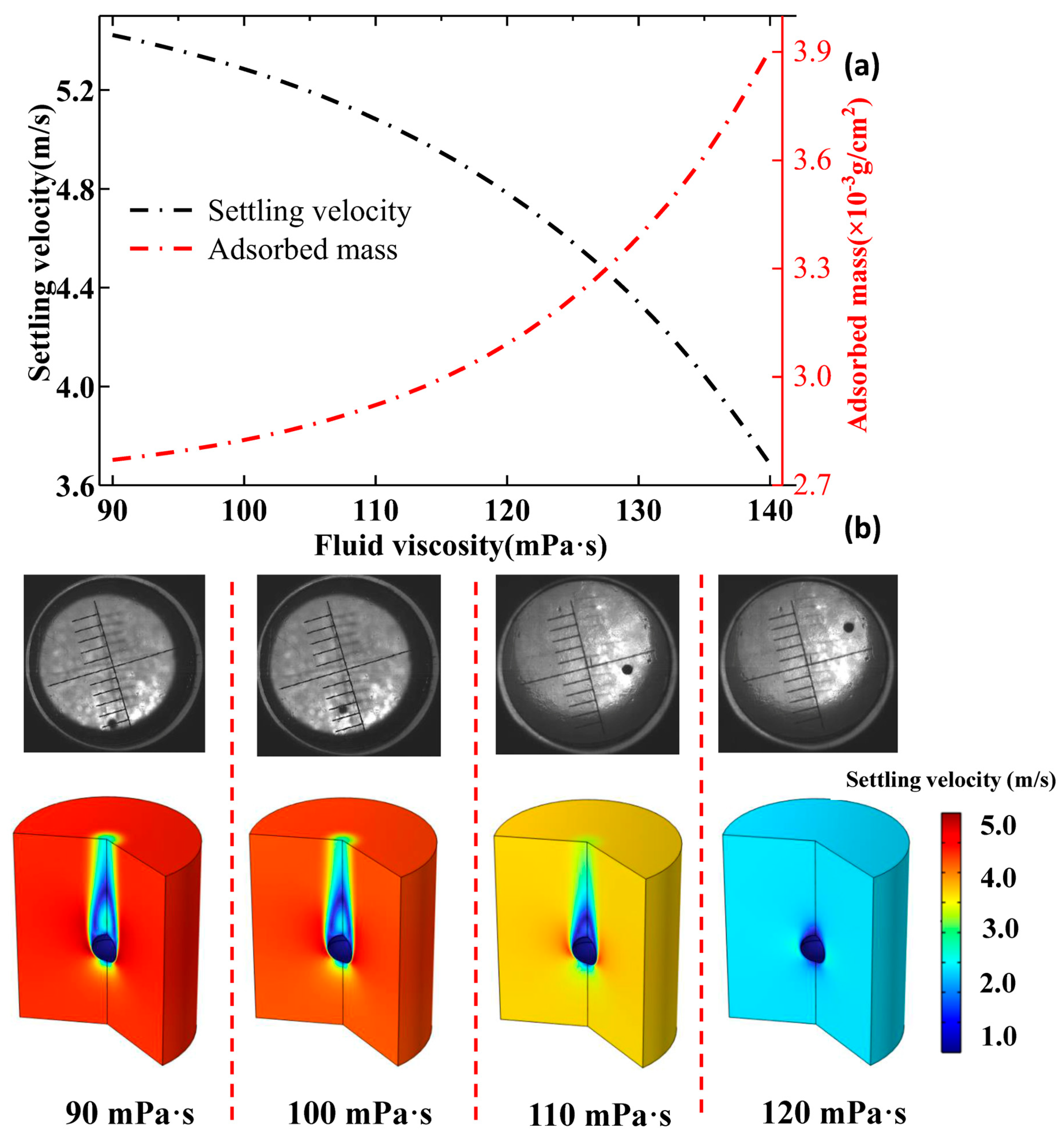
The settling behavior of proppant particles within hydraulic fractures plays a crucial role in determining fracture conductivity and the overall effectiveness of hydraulic fracturing operations. Because particle transport and suspension are strongly governed by the rheological properties of the carrier fluid, fluid viscosity represents one of the key parameters controlling proppant distribution within the fracture. Figure 10 illustrates the influence of fluid viscosity on particle settling behavior in different water-based fracturing fluids, providing important guidance for optimizing fracturing fluid design and proppant placement. As shown in Figure 10, particle settling velocity exhibits a pronounced negative correlation with fluid viscosity. Specifically, the settling behavior can be divided into two distinct regimes: a rapid-settling regime at relatively low viscosities and a suspension-dominated regime at higher viscosities. Increasing the fluid viscosity from 90 mPa·s to 100 mPa·s reduces the particle settling velocity from 5.4 m/s to 5.3 m/s, whereas a further increase in viscosity to 120 mPa·s decreases the settling velocity to 4.8 m/s. These results demonstrate that fluid viscosity substantially enhances the suspension capacity of the fracturing fluid and effectively suppresses particle settling, thereby promoting more uniform proppant transport within the fracture. The macroscopic relationship between fluid viscosity and particle settling behavior is consistent with the prediction of Stokes’ law (Equation (16)). Furthermore, the underlying mechanism can be interpreted from a molecular-scale perspective by considering the evolution of the intermolecular network and its influence on the rheological properties of the fracturing fluid, thereby establishing a direct link between molecular interactions and the macroscopic settling behavior of proppant particles.
The settling behavior of proppant particles in water-based fracturing fluids is governed by the balance between gravitational forces and hydrodynamic resistance, which together determine particle transport and suspension within hydraulic fractures [118]. Although gravity drives particle settling, the settling velocity is progressively reduced by the hydrodynamic drag exerted by the surrounding fluid. The magnitude of this drag is strongly dependent on the rheological properties of the fracturing fluid, which are governed at the molecular scale by intermolecular interactions and polymer network formation [119]. Previous studies have demonstrated that the viscosity of water-based fracturing fluids is commonly understood to be controlled by the density and stability of the hydrogen bond network, together with other intermolecular interactions between water molecules and polymeric additives [120]. As fluid viscosity increases, the intermolecular network becomes denser and more stable, resulting in greater resistance to particle motion and consequently enhancing the hydrodynamic drag acting on suspended particles. However, fluid rheology alone does not fully determine particle settling behavior. Adsorption of polymeric additives and crosslinking agents onto particle surfaces also plays a critical role by modifying the particle–fluid interfacial properties and strengthening the interaction between the particles and the surrounding fluid [121]. The adsorbed polymer layer effectively increases the hydrodynamic coupling between the particles and the viscous fluid, thereby enhancing drag and reducing particle settling velocity [122]. As illustrated in Figure 10, the adsorption capacity increases with fluid viscosity, which is consistent with the observed reduction in settling velocity. These results indicate that particle settling behavior is jointly regulated by fluid viscosity and surface adsorption [123]. Their combined effects enhance particle suspension and transport within hydraulic fractures, thereby improving proppant placement and increasing the long-term conductivity of the created fracture network.
Figure 10. Settling velocity and adsorption behavior in fluids of different viscosities. (a) Data curve. (b) Sedimentation experiments and numerical models. (Deterministic numerical results; see Section 2.4 for parameter sensitivity.).
Processes 14 02923 g010

3.3. Fracturing Fluid Sweep Area and Stimulation Effectiveness

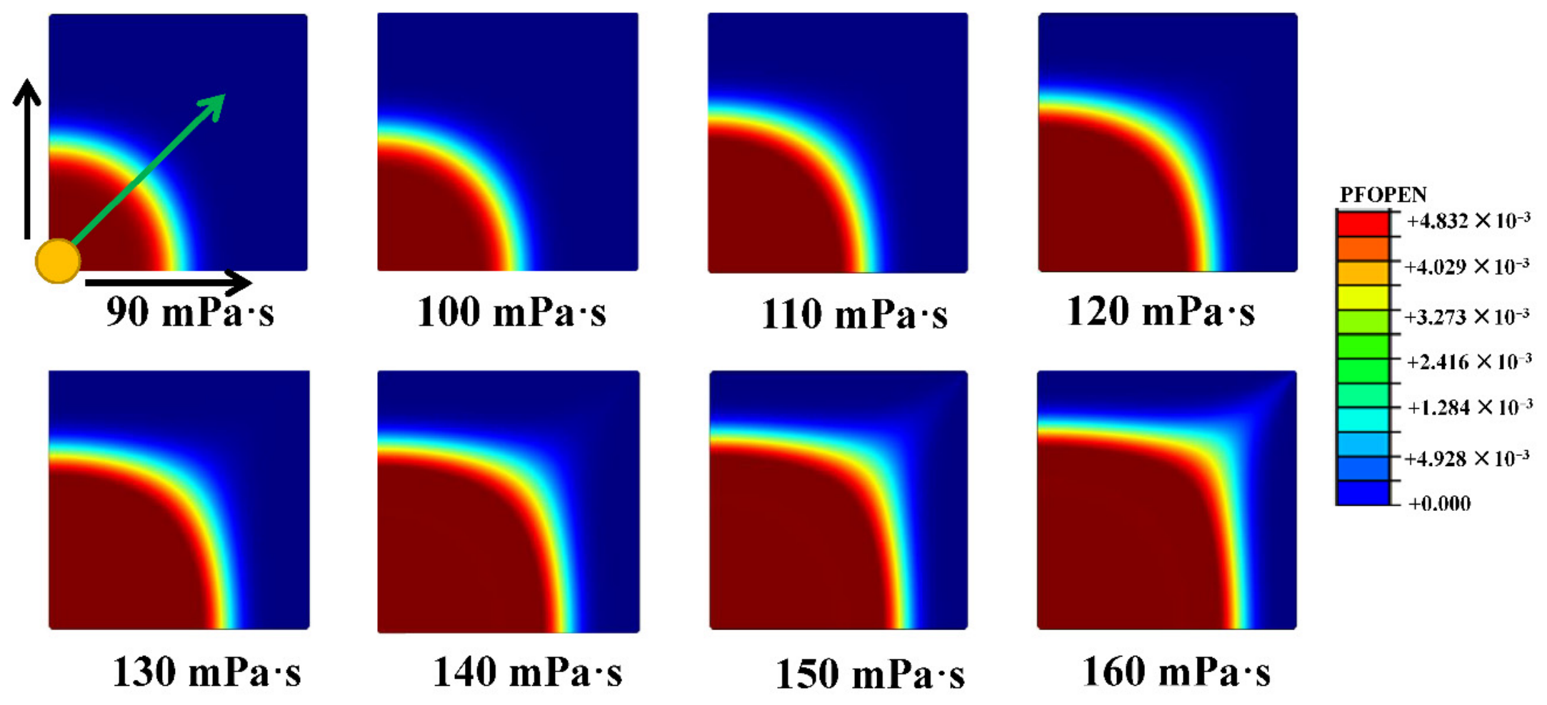
The sweep area of the fracturing fluid provides an important measure of reservoir stimulation performance, reflecting the extent of fluid distribution and the effective contact area within the reservoir. It should be noted that actual hydrocarbon recovery (cumulative production or recovery factor) is not calculated in the present study, and the sweep area is used only as a proxy for stimulation effectiveness. Figure 11 presents the variation in fracturing fluid sweep area at different fluid viscosities, providing quantitative guidance for optimizing fracturing fluid design and improving reservoir development strategies. As shown in Figure 11, low-viscosity water-based fracturing fluids produce a relatively limited sweep area, whereas increasing fluid viscosity substantially enlarges the swept region and expands the effective stimulation zone. A pronounced positive correlation is observed between fluid viscosity and sweep area, indicating that higher-viscosity fluids promote more extensive reservoir stimulation. This trend is consistent with the positive relationship between fluid viscosity and fracture length observed in Figure 10, demonstrating that enhanced fluid viscosity not only facilitates fracture propagation, but also improves the spatial distribution of the fracturing fluid within the reservoir. Consequently, high-viscosity fracturing fluids are more favorable for increasing reservoir contact area and improving the overall effectiveness of hydraulic fracturing operations.
Figure 11. Fracturing fluid sweep area at different fluid viscosities in geological reservoirs. (Deterministic numerical results; see Section 2.4 for parameter sensitivity.).
Processes 14 02923 g011
The relatively limited sweep area observed for low-viscosity water-based fracturing fluids can be primarily attributed to their high fluid leak-off, a phenomenon that can be interpreted from the perspective of molecular interactions and the evolution of the intermolecular network [124]. At low viscosities, the hydrogen bond network and other intermolecular interactions are relatively weak, resulting in a less developed three-dimensional molecular structure. Consequently, the mobility of water molecules is only weakly constrained, allowing a larger proportion of mobile water molecules to migrate into the surrounding rock matrix through pore throats and microfractures [125]. The resulting increase in fluid leak-off accelerates pressure dissipation within the hydraulic fracture, reduces the net fracture pressure available for fracture extension, and ultimately suppresses fracture propagation, thereby limiting the sweep area of the fracturing fluid [126]. The reduction in net fracture pressure weakens the hydraulic driving force for fracture extension, thereby suppressing fracture propagation and limiting the sweep area of the fracturing fluid [127]. In contrast, high-viscosity fracturing fluids exhibit a denser and more stable intermolecular network formed through enhanced hydrogen bonding and polymer interactions. This interconnected network effectively restricts the mobility of water molecules, significantly reducing fluid leak-off and improving pressure retention within the hydraulic fracture [128]. Consequently, a higher net fracture pressure is maintained, allowing the fracture to more effectively overcome the effective in situ stress and propagate over a larger distance [129]. The resulting enhancement in fracture growth substantially expands the sweep area of the fracturing fluid, thereby improving reservoir stimulation effectiveness, as indicated by the enlarged fracturing fluid sweep area.

4. Conclusions

This study established a fully coupled thermo-hydro-mechanical (THM) numerical model to investigate hydraulic fracture propagation behavior in geological reservoirs. The model integrates fluid flow, heat transfer, rock deformation, damage evolution, and fluid–rock interactions. The quantitative results show that increasing fluid viscosity from 80 mPa·s to 130 mPa·s increases fracture length from 35 m to 50 m (approximately 43% increase). Higher reservoir porosity and larger fracture deflection angles reduce fracture length, with the most pronounced suppression occurring beyond a critical deflection angle. Elevated reservoir temperature progressively suppresses fracture propagation, whereas increasing reservoir pressure promotes fracture extension. Sensitivity analysis further indicates that fracture length varies by up to ±15–18% with initial permeability and by smaller amounts (±4–8%) with thermal expansion coefficient, damage–permeability coupling coefficient, and the fully damaged permeability jump coefficient ξ. These macroscopic trends are consistently explained by microscopic molecular-scale mechanisms involving hydrogen bond network stability and fluid leak-off. The model was benchmarked against independent numerical results, achieving agreement within 5.3% for breakdown pressure and R2 = 0.94 for fracture half-length. It should be noted that the present work focuses on fracture geometry, leak-off, and multiphysics damage evolution; cumulative oil production was not simulated and is therefore not reported. The model is two-dimensional and assumes a continuous, homogeneous, and isotropic porous medium. These idealizations differ significantly from the bedding planes, natural fractures, and spatial heterogeneity that characterize real shale and granite reservoirs. The simplified framework was adopted to isolate the fundamental multiphysics coupling processes; however, it constitutes a clear limitation of the present study. Future work will therefore focus on extending the model to three-dimensional heterogeneous conditions that explicitly incorporate bedding planes, discrete fracture networks, and spatial variability of rock properties. Future work will extend the model to three-dimensional heterogeneous conditions that incorporate bedding, discrete fracture networks, and property variability, include long-term geochemical effects, pursue further validation against laboratory experiments and field data, and refine the classical maximum tensile stress and Mohr–Coulomb criteria for extreme high-temperature and high-pressure conditions.

Author Contributions

Conceptualization, L.W. and Y.Z.; methodology, Z.M.; software, Z.M.; validation, C.Z.; formal analysis, C.Z. and F.F.; investigation, F.F., X.L. (Xiaobo Lin), and Y.X.; resources, L.W.; writing—original draft, L.W. and X.L. (Xinjia Liu); writing—review and editing, F.W. and Y.G.; visualization, Y.G.; supervision, Y.G. and X.L. (Xinjia Liu); project administration, L.W. All authors have read and agreed to the published version of the manuscript.

Funding

This research received no external funding.

Data Availability Statement

The data and supportive information are available within this article.

Conflicts of Interest

Authors Lili Wang, Yanming Zhang, Zhanguo Ma, Changjing Zhou, Fei Feng, Yonghong Gu, Xinjia Liu, Xiaobo Lin, and Yuhang Xie were employed by China National Petroleum Corporation. The remaining authors declare that the research was conducted in the absence of any commercial or financial relationships that could be construed as a potential conflict of interest.

References

  1. Xu, C.; Dowd, P.A.; Tian, Z.F. A simplified coupled hydro-thermal model for enhanced geothermal systems. Appl. Energy 2015, 140, 135–145. [Google Scholar] [CrossRef] [Scilit]
  2. Ismail, A.; Azadbakht, S. A comprehensive review of numerical simulation methods for hydraulic fracturing. Int. J. Numer. Anal. Methods Geomech. 2024, 48, 1433–1459. [Google Scholar] [CrossRef] [Scilit]
  3. Li, L.C.; Tang, C.A.; Li, G.; Wang, S.Y.; Liang, Z.Z.; Zhang, Y.B. Numerical simulation of 3D hydraulic fracturing based on an improved flow-stress-damage model and a parallel FEM technique. Rock Mech. Rock Eng. 2012, 45, 801–818. [Google Scholar] [CrossRef] [Scilit]
  4. Li, Q.; You, D.; Li, Q.; Wang, F.; Wang, Y.; Yang, Y. Analysis of sedimentation behavior and influencing factors of solid particles in CO2 fracturing fluid. Processes 2025, 13, 4049. [Google Scholar] [CrossRef] [Scilit]
  5. Ren, Q.-Q.; Li, L.-F.; Wang, J.; Jiang, R.-T.; Li, M.-P.; Feng, J.-W. Dynamic evolution mechanism of the fracturing fracture system—Enlightenments from hydraulic fracturing physical experiments and finite element numerical simulation. Pet. Sci. 2024, 21, 3839–3866. [Google Scholar] [CrossRef] [Scilit]
  6. Li, Q.; Wang, F.; Wu, J.; Li, Q.; Zhang, G. Multivariate Coupling Model and Reservoir Characteristics of Enhanced Geothermal Reservoirs. Energies 2026, 19, 3180. [Google Scholar] [CrossRef] [Scilit]
  7. Taleghani, A.D.; Gonzalez-Chavez, M.; Yu, H.; Asala, H. Numerical simulation of hydraulic fracture propagation in naturally fractured formations using the cohesive zone model. J. Pet. Sci. Eng. 2018, 165, 42–57. [Google Scholar] [CrossRef] [Scilit]
  8. Wu, H.; Lyu, X.; Shang, X.; Huang, X.; Chang, Y. A Sensitivity-Driven Inversion Framework for Efficient Calibration of 3D Geomechanical Models: Application to a Shale Reservoir. Reserv. Sci. 2026, 2, 305–323. [Google Scholar] [CrossRef] [Scilit]
  9. Lu, C.; Ma, L.; Li, Z.; Huang, F.; Huang, C.; Yuan, H.; Tang, Z.; Guo, J. A novel hydraulic fracturing method based on the coupled CFD-DEM numerical simulation study. Appl. Sci. 2020, 10, 3027. [Google Scholar] [CrossRef] [Scilit]
  10. Guo, T.; Hao, T.; Yang, X.; Li, Q.; Liu, Y.; Chen, M.; Qu, Z. Numerical simulation study of fracture propagation by internal plugging hydraulic fracturing. Eng. Fract. Mech. 2024, 310, 110480. [Google Scholar] [CrossRef] [Scilit]
  11. Xu, B.; Liu, Y.; Wang, Y.; Yang, G.; Yu, Q.; Wang, F. A new method and application of full 3D numerical simulation for hydraulic fracturing horizontal fracture. Energies 2018, 12, 48. [Google Scholar] [CrossRef] [Scilit]
  12. Hu, J.; Cao, J.X.; He, X.Y.; Wang, Q.F.; Xu, B. Numerical simulation of fault activity owing to hydraulic fracturing. Appl. Geophys. 2018, 15, 367–381. [Google Scholar] [CrossRef] [Scilit]
  13. Shi, X.; Qin, Y.; Xu, H.; Feng, Q.; Wang, S.; Xu, P.; Han, S. Numerical simulation of hydraulic fracture propagation in conglomerate reservoirs. Eng. Fract. Mech. 2021, 248, 107738. [Google Scholar] [CrossRef] [Scilit]
  14. Ma, X.; Sun, Y.; Guo, W.; Jia, R.; Li, B. Numerical simulation of horizontal well hydraulic fracturing technology for gas production from hydrate reservoir. Appl. Ocean Res. 2021, 112, 102674. [Google Scholar] [CrossRef] [Scilit]
  15. Lizhe, L.; Fujian, Z.; You, Z.; Zhuolin, C.; Bo, W.; Yingying, Z.; Yutian, L. The prediction and optimization of Hydraulic fracturing by integrating the numerical simulation and the machine learning methods. Energy Rep. 2022, 8, 15338–15349. [Google Scholar] [CrossRef] [Scilit]
  16. Wu, J.; Li, Q.; Li, Q.; Wang, F.; Cheng, Y.; Yan, C. Design and Optimization of Bottom-Hole Temperature–Pressure Combinations in Gas Production from Gas Hydrates via Carbon Dioxide Replacement Strategy. Energies 2026, 19, 3536. [Google Scholar] [CrossRef] [Scilit]
  17. Yang, P.; Zhang, S.; Zou, Y.; Zhong, A.; Yang, F.; Zhu, D.; Chen, M. Numerical Simulation of integrated three-dimensional hydraulic fracture propagation and proppant transport in multi-well pad fracturing. Comput. Geotech. 2024, 167, 106075. [Google Scholar] [CrossRef] [Scilit]
  18. Li, Q.; Li, Q.; Wang, F.; Xu, N.; Wang, Y.; Bai, B. Settling behavior and mechanism analysis of kaolinite as a fracture proppant of hydrocarbon reservoirs in CO2 fracturing fluid. Colloids Surf. A Physicochem. Eng. Asp. 2025, 724, 137463. [Google Scholar] [CrossRef] [Scilit]
  19. Wu, M.Y.; Zhang, D.M.; Wang, W.S.; Li, M.H.; Liu, S.M.; Lu, J.; Gao, H. Numerical simulation of hydraulic fracturing based on two-dimensional surface fracture morphology reconstruction and combined finite-discrete element method. J. Nat. Gas Sci. Eng. 2020, 82, 103479. [Google Scholar] [CrossRef] [Scilit]
  20. Sun, C.; Zheng, H.; Liu, W.D.; Lu, W. Numerical simulation analysis of vertical propagation of hydraulic fracture in bedding plane. Eng. Fract. Mech. 2020, 232, 107056. [Google Scholar] [CrossRef] [Scilit]
  21. Tian, W.; Li, P.; Dong, Y.; Lu, Z.; Lu, D. Numerical simulation of sequential, alternate and modified zipper hydraulic fracturing in horizontal wells using XFEM. J. Pet. Sci. Eng. 2019, 183, 106251. [Google Scholar] [CrossRef] [Scilit]
  22. Eveline, V.F.; Akkutlu, I.Y.; Moridis, G.J. Numerical simulation of hydraulic fracturing water effects on shale gas permeability alteration. Transp. Porous Media 2017, 116, 727–752. [Google Scholar] [CrossRef] [Scilit]
  23. Liu, X.; Rasouli, V.; Guo, T.; Qu, Z.; Sun, Y.; Damjanac, B. Numerical simulation of stress shadow in multiple cluster hydraulic fracturing in horizontal wells based on lattice modelling. Eng. Fract. Mech. 2020, 238, 107278. [Google Scholar] [CrossRef] [Scilit]
  24. Guo, T.; Hao, T.; Chen, M.; Zhang, Y.; Qu, Z.; Jia, X.; Zhang, W.; Yu, H. Numerical simulation on Geothermal extraction by radial well assisted hydraulic fracturing. Renew. Energy 2023, 210, 440–450. [Google Scholar] [CrossRef] [Scilit]
  25. Ma, X.; Cheng, J.; Sun, Y.; Li, S. 2D numerical simulation of hydraulic fracturing in hydrate-bearing sediments based on the cohesive element. Energy Fuels 2021, 35, 3825–3840. [Google Scholar] [CrossRef] [Scilit]
  26. Li, Q.; Li, Q.; Wang, F.; Wu, J.; Wang, Y.; Jin, J. Effects of geological and fluid characteristics on the injection filtration of hydraulic fracturing fluid in the wellbores of shale reservoirs: Numerical analysis and mechanism determination. Processes 2025, 13, 1747. [Google Scholar] [CrossRef] [Scilit]
  27. Zhang, X.; Si, G.; Bai, Q.; Xiang, Z.; Li, X.; Oh, J.; Zhang, Z. Numerical simulation of hydraulic fracturing and associated seismicity in lab-scale coal samples: A new insight into the stress and aperture evolution. Comput. Geotech. 2023, 160, 105507. [Google Scholar] [CrossRef] [Scilit]
  28. Zhang, Z.; Sun, Q.; Wang, H.; Chen, C.; Chen, C.; Zhou, Q.; Gong, Q.; Zhuo, X.; Zhuo, P. The impact of reservoir parameters and fluid properties on seepage characteristics and fracture morphology using water-based fracturing fluid. Processes 2025, 13, 3166. [Google Scholar] [CrossRef] [Scilit]
  29. Li, Q.; Li, Q.; Cao, H.; Wu, J.; Wang, F.; Wang, Y. The crack propagation behaviour of CO2 fracturing fluid in unconventional low permeability reservoirs: Factor analysis and mechanism revelation. Processes 2025, 13, 159. [Google Scholar] [CrossRef] [Scilit]
  30. Cong, Z.; Li, Y.; Tang, J.; Martyushev, D.A.; Yang, F. Numerical simulation of hydraulic fracture height layer-through propagation based on three-dimensional lattice method. Eng. Fract. Mech. 2022, 264, 108331. [Google Scholar] [CrossRef] [Scilit]
  31. Liu, X.; Sun, Y.; Guo, T.; Rabiei, M.; Qu, Z.; Hou, J. Numerical simulations of hydraulic fracturing in methane hydrate reservoirs based on the coupled thermo-hydrologic-mechanical-damage (THMD) model. Energy 2022, 238, 122054. [Google Scholar] [CrossRef] [Scilit]
  32. Liu, Y.F.; Li, W.; Xiao, Z.H.; Ji, S.W.; Liu, Q.; Tang, Y.F.; Zhang, Y.; Wang, J.M. Recent Progress in Organic Inhibitors for Anticorrosion in Complex Acid Environments. Coatings 2026, 16, 150. [Google Scholar] [CrossRef] [Scilit]
  33. Chen, M.; Guo, T.; Zou, Y.; Zhang, S.; Qu, Z. Numerical simulation of proppant transport coupled with multi-planar-3D hydraulic fracture propagation for multi-cluster fracturing. Rock Mech. Rock Eng. 2022, 55, 565–590. [Google Scholar] [CrossRef] [Scilit]
  34. Wang, L.; Dong, Y.; Zhang, Q.; Duan, R. Numerical simulation of pressure evolution and migration of hydraulic fracturing fluids in the shale gas reservoirs of Sichuan Basin, China. J. Hydrol. 2020, 588, 125082. [Google Scholar] [CrossRef] [Scilit]
  35. Li, Q.; Li, Q.; Wu, J.; He, K.; Xia, Y.; Liu, J.; Wang, F.; Cheng, Y. Wellhead Stability During Development Process of Hydrate Reservoir in the Northern South China Sea: Sensitivity Analysis. Processes 2025, 13, 1630. [Google Scholar] [CrossRef] [Scilit]
  36. Adamu, M.A.; Ali, A.M.; Kasim, S. Supervised Seismic Facies Classification in Ataga Field of Niger Delta Basin using a Thalweg Tracker and Deep Learning Approach. Reserv. Sci. 2026, 2, 289–304. [Google Scholar] [CrossRef] [Scilit]
  37. Liu, Y.F.; Zhou, L.; Wan, X.C.; Tang, Y.F.; Liu, Q.; Li, W.; Liao, J. Synthesis and Characterization of a Temperature-Sensitive Microcapsule Gelling Agent for High-Temperature Acid Release. ACS Omega 2024, 9, 20849–20858. [Google Scholar] [CrossRef] [Scilit]
  38. Wang, W.; Guo, X.; Duan, P.; Kang, B.; Zheng, D.; Zafar, A. Investigation of plugging performance and enhanced oil recovery of multi-scale polymer microspheres in low-permeability reservoirs. Nat. Gas Ind. B 2023, 10, 223–232. [Google Scholar] [CrossRef] [Scilit]
  39. Huang, L.; Liao, X.; Fan, M.; Wu, S.; Tan, P.; Yang, L. Experimental and numerical simulation technique for hydraulic fracturing of shale formations. Adv. Geo-Energy Res. 2024, 13, 83–88. [Google Scholar] [CrossRef] [Scilit]
  40. Ao, F.; Qingchao, L.; Qiang, L.; Jingjuan, W.; Fuling, W.; Chuanliang, Y. Numerical Simulation Investigation of Fracture Propagation Behavior Patterns and Sensitivity Factors of Oil Shale Reservoirs in the Xunyi Region Considering the Influence of Natural Fracture. Geofluids 2025, 2025, 2762142. [Google Scholar] [CrossRef] [Scilit]
  41. Mwakipunda, G.C.; Komba, N.A.; Ayimadu, E.T.; Yu, L. Model Development for Brittleness Index Estimation and Depth Determination in Hydraulic Fracturing Operations in Shale Gas Reservoirs Using Machine Learning Algorithms. SPE J. 2025, 30, 4409–4430. [Google Scholar] [CrossRef] [Scilit]
  42. Guo, T.; Tang, S.; Liu, S.; Liu, X.; Zhang, W.; Qu, G. Numerical simulation of hydraulic fracturing of hot dry rock under thermal stress. Eng. Fract. Mech. 2020, 240, 107350. [Google Scholar] [CrossRef] [Scilit]
  43. Li, Q.; Li, Q.; Han, Y. A numerical investigation on kick control with the displacement kill method during a well test in a deep-water gas reservoir: A case study. Processes 2024, 12, 2090. [Google Scholar] [CrossRef] [Scilit]
  44. Yaobin, S.; Weiyong, L.; Changchun, H.; Erhu, B. Numerical simulation of the influence of natural fractures on hydraulic fracture propagation. Geofluids 2020, 2020, 8878548. [Google Scholar] [CrossRef] [Scilit]
  45. Zhang, K.; Gao, Y.; Chen, S.; Tan, Z.; Wu, X.; Wang, W.; Tian, Y.; Su, Y.; Liu, S.; Wang, H. Determination of Reserve Parameters of Gulong Shale Oil Reservoir and Its Geological Significance. Reserv. Sci. 2026, 2, 276–288. [Google Scholar] [CrossRef] [Scilit]
  46. Lv, M.; Guo, T.; Chen, M.; Liu, Y.; Yang, X.; Qu, Z.; Dai, C. Review of proppant flowback after hydraulic fracturing: Research, control, and prediction methods. Geoenergy Sci. Eng. 2025, 246, 213651. [Google Scholar] [CrossRef] [Scilit]
  47. Li, Q.; Li, Q.; Wang, F.; Wu, J.; Wang, Y. The carrying behavior of water-based fracturing fluid in shale reservoir fractures and molecular dynamics of sand-carrying mechanism. Processes 2024, 12, 2051. [Google Scholar] [CrossRef] [Scilit]
  48. Wu, J.; Ansari, U. From CO2 Sequestration to Hydrogen Storage: Further Utilization of Depleted Gas Reservoirs. Reserv. Sci. 2025, 1, 19–35. [Google Scholar] [CrossRef] [Scilit]
  49. Li, Y.; Hu, W.; Zhang, Z.; Zhang, Z.; Shang, Y.; Han, L.; Wei, S. Numerical simulation of hydraulic fracturing process in a naturally fractured reservoir based on a discrete fracture network model. J. Struct. Geol. 2021, 147, 104331. [Google Scholar] [CrossRef] [Scilit]
  50. Zhu, X.; Wei, S.; Luo, W.; Gong, X.; Chu, Y. Numerical simulation and experimental study on improving gas drainage by hydraulic fracturing. Energy Sources Part A Recovery Util. Environ. Eff. 2023, 45, 1965–1982. [Google Scholar] [CrossRef] [Scilit]
  51. Li, Q.; Liu, J.; Wang, S.; Guo, Y.; Han, X.; Li, Q.; Cheng, Y.; Dong, Z.; Li, X.; Zhang, X. Numerical insights into factors affecting collapse behavior of horizontal wellbore in clayey silt hydrate-bearing sediments and the accompanying control strategy. Ocean Eng. 2024, 297, 117029. [Google Scholar] [CrossRef] [Scilit]
  52. Dalla Barba, F.; Picano, F. A novel approach for direct numerical simulation of hydraulic fracture problems. Flow Turbul. Combust. 2020, 105, 335–357. [Google Scholar] [CrossRef] [Scilit]
  53. Fan, Y.; Shu, L.; Huo, Z.; Hao, J.; Yang, L. Numerical simulation research on hydraulic fracturing promoting coalbed methane extraction. Shock Vib. 2021, 2021, 3269592. [Google Scholar] [CrossRef] [Scilit]
  54. Tang, H.; Luo, S.; Liang, H.; Zeng, B.; Zhang, L.; Zhao, Y.; Song, Y. Integrated numerical simulation of hydraulic fracturing and production in shale gas well considering gas-water two-phase flow. Pet. Explor. Dev. 2024, 51, 684–696. [Google Scholar] [CrossRef] [Scilit]
  55. Li, Q. Reservoir Science: One Year On–Achievements, Challenges, and Future Prospects. Reserv. Sci. 2026, 2, 272–275. [Google Scholar] [CrossRef] [Scilit]
  56. Zhou, T.; Wang, H.; Li, F.; Li, Y.; Zou, Y.; Zhang, C. Numerical simulation of hydraulic fracture propagation in laminated shale reservoirs. Pet. Explor. Dev. 2020, 47, 1117–1130. [Google Scholar] [CrossRef] [Scilit]
  57. Li, Q.; Wang, F.; Forson, K.; Zhang, J.; Zhang, C.; Chen, J.; Xu, N.; Wang, Y. Affecting analysis of the rheological characteristic and reservoir damage of CO2 fracturing fluid in low permeability shale reservoir. Environ. Sci. Pollut. Res. 2022, 29, 37815–37826. [Google Scholar] [CrossRef] [Scilit]
  58. Kang, H.; Xia, Y.; Feng, M.; Lu, C.; Gao, F. Case study of hydraulic fracturing for coal burst risk mitigation. Int. J. Coal Sci. Technol. 2025, 12, 61. [Google Scholar] [CrossRef] [Scilit]
  59. Yang, K.; Gao, D. Numerical simulation of hydraulic fracturing process with consideration of fluid–solid interaction in shale rock. J. Nat. Gas Sci. Eng. 2022, 102, 104580. [Google Scholar] [CrossRef] [Scilit]
  60. Li, Q.; Cheng, Y.; Li, Q.; Zhang, C.; Ansari, U.; Song, B. Establishment and evaluation of strength criterion for clayey silt hydrate-bearing sediments. Energy Sources Part A Recovery Util. Environ. Eff. 2018, 40, 742–750. [Google Scholar] [CrossRef] [Scilit]
  61. Wang, J.; Guo, T.; Chen, M.; Qu, Z.; Zhang, B.; Zhang, W.; Zhai, C.; Zheng, P. Numerical simulation of fracture propagation morphology in hydraulic fracturing development of geothermal reservoirs based on the CDEM-THM3D. Comput. Geotech. 2024, 172, 106444. [Google Scholar] [CrossRef] [Scilit]
  62. Ma, J.; Li, X.; Yao, Q.; Tan, K. Numerical simulation of hydraulic fracture extension patterns at the interface of coal-measure composite rock mass with Cohesive Zone Model. J. Clean. Prod. 2023, 426, 139001. [Google Scholar] [CrossRef] [Scilit]
  63. Han, L.; Zhou, X. Numerical Simulations of the Hydraulic Fracture Propagation in Poroelastic Media Using the Coupled Hydro-Mechanical Field-Enriched Finite Element Method. Rock Mech. Rock Eng. 2025, 58, 245–274. [Google Scholar] [CrossRef] [Scilit]
  64. Zhai, M.; Wang, D.; Zhang, Z.; Zhang, L.; Yang, F.; Huang, B.; Zhong, A.; Li, L. Numerical simulation and multi-factor optimization of hydraulic fracturing in deep naturally fractured sandstones based on response surface method. Eng. Fract. Mech. 2022, 259, 108110. [Google Scholar] [CrossRef] [Scilit]
  65. Yan, X.; Yu, H. Numerical simulation of hydraulic fracturing with consideration of the pore pressure distribution based on the unified pipe-interface element model. Eng. Fract. Mech. 2022, 275, 108836. [Google Scholar] [CrossRef] [Scilit]
  66. Hu, X.; Huang, G.; Zhou, F.; Qiu, Y.; Gou, X.; Chen, C. Pressure response using wavelet analysis in the process of hydraulic fracturing: Numerical simulation and field case. J. Pet. Sci. Eng. 2022, 217, 110837. [Google Scholar] [CrossRef] [Scilit]
  67. Li, Q.; Li, Q.; Wu, J.; Li, X.; Li, H.; Cheng, Y. Wellhead Stability During Development Process of Hydrate Reservoir in the Northern South China Sea: Evolution and Mechanism. Processes 2025, 13, 40. [Google Scholar] [CrossRef] [Scilit]
  68. Li, Q.; Wu, J.; Li, Q.; Wang, F.; Cheng, Y. Sediment Instability Caused by Gas Production from Hydrate-Bearing Sediment in Northern South China Sea by Horizontal Wellbore: Sensitivity Analysis. Nat. Resour. Res. 2025, 34, 1667–1699. [Google Scholar] [CrossRef] [Scilit]
  69. Zhang, B.; Guo, T.; Qu, Z.; Wang, J.; Chen, M.; Liu, X. Numerical simulation of fracture propagation and production performance in a fractured geothermal reservoir using a 2D FEM-based THMD coupling model. Energy 2023, 273, 127175. [Google Scholar] [CrossRef] [Scilit]
  70. Zeng, H.; Jin, Y.; Wang, D.; Yu, B.; Zhang, W. Numerical simulation on hydraulic fracture height growth across layered elastic–plastic shale oil reservoirs. Processes 2022, 10, 1453. [Google Scholar] [CrossRef] [Scilit]
  71. Shi, X.; Ge, X.; Gao, Q.; Han, S.; Zhang, Y.; Kong, X. Numerical simulation of hydraulic fracture propagation from recompletion in refracturing with dynamic stress modeling. Geomech. Geophys. Geo-Energy Geo-Resour. 2024, 10, 155. [Google Scholar] [CrossRef] [Scilit]
  72. Onwubuariri, C.N.; Aigba, P.I.; Dinneya, O.C.; Nwokoma, E.U. Integrated Seismic Interpretation and Petrophysical Evaluation for Hydrocarbon Volumetric Estimation in the BUKS Offshore Field, Niger Delta, Nigeria. Reserv. Sci. 2026, 2, 261–271. [Google Scholar] [CrossRef] [Scilit]
  73. Wang, D.; Li, S.; Zhang, D.; Pan, Z. Understanding and predicting proppant bedload transport in hydraulic fracture via numerical simulation. Powder Technol. 2023, 417, 118232. [Google Scholar] [CrossRef] [Scilit]
  74. Li, Q.; Wang, F.; Wang, Y.; Bai, B.; Zhang, J.; Lili, C.; Sun, Q.; Wang, Y.; Forson, K. Adsorption behavior and mechanism analysis of siloxane thickener for CO2 fracturing fluid on shallow shale soil. J. Mol. Liq. 2023, 376, 121394. [Google Scholar] [CrossRef] [Scilit]
  75. Fu, H.; Huang, L.; Hou, B.; Weng, D.; Guan, B.; Zhong, T.; Zhao, Y. Experimental and numerical investigation on interaction mechanism between hydraulic fracture and natural fracture. Rock Mech. Rock Eng. 2024, 57, 10571–10582. [Google Scholar] [CrossRef] [Scilit]
  76. Nawab, S.; Ali, M.; Hullio, I.A.; Noshad; Liu, N.; Jokhio, S.A. A Machine Learning Framework for Artificial Lift Method Selection with Physics-Informed Data Balancing. Reserv. Sci. 2026, 2, 228–260. [Google Scholar] [CrossRef] [Scilit]
  77. Yin, P.F.; Yang, S.Q.; Gao, F.; Tian, W.L.; Zeng, W. Numerical investigation on hydraulic fracture propagation and multi-perforation fracturing for horizontal well in Longmaxi shale reservoir. Theor. Appl. Fract. Mech. 2023, 125, 103921. [Google Scholar] [CrossRef] [Scilit]
  78. Zhao, J.; Wang, Z.; Lin, R.; Ren, L.; Wu, J.; Wu, J. Numerical simulation of diverting fracturing for staged fracturing horizontal well in shale gas reservoir. J. Energy Resour. Technol. 2023, 145, 053202. [Google Scholar] [CrossRef] [Scilit]
  79. Li, Q.; Wang, F.; Wang, Y.; Zhou, C.; Chen, J.; Forson, K.; Miao, R.; Su, Y.; Zhang, J. Effect of reservoir characteristics and chemicals on filtration property of water-based drilling fluid in unconventional reservoir and mechanism disclosure. Environ. Sci. Pollut. Res. 2023, 30, 55034–55043. [Google Scholar] [CrossRef] [Scilit]
  80. Zhu, D.; Han, G.; Zou, H.; Cui, M.; Liang, C.; Yao, F. A review of the hydraulic fracturing in ductile reservoirs: Theory, simulation, and experiment. Processes 2022, 10, 2022. [Google Scholar] [CrossRef] [Scilit]
  81. Min, Q.; Zhang, M.; Li, M.; He, Y.; Bordas, S.P.; Zhang, H. Hydraulic fracturing simulation of concrete dam integrating intelligent crack detection and refined modeling methods. Eng. Struct. 2024, 305, 117760. [Google Scholar] [CrossRef] [Scilit]
  82. Xia, Y.; Yao, M.; Li, T.; Yang, H.; Tang, C.A. Numerical analysis of hydraulic fracture propagation in deep shale reservoir with different injection strategies. J. Rock Mech. Geotech. Eng. 2024, 16, 3558–3574. [Google Scholar] [CrossRef] [Scilit]
  83. Ran, Q.; Zhou, X.; Dong, J.; Xu, M.; Ren, D.; Li, R. Numerical simulation of multi-fracture propagation based on the extended finite element method. Processes 2023, 11, 2032. [Google Scholar] [CrossRef] [Scilit]
  84. Zhang, Y.; Guo, T.; Chen, M.; Qu, Z.; Cao, J.; Yang, X.; Fu, H.; Zhang, X. Numerical simulation study of fracture height growth considering the influence of bedding planes. Comput. Geotech. 2024, 168, 106144. [Google Scholar] [CrossRef] [Scilit]
  85. Wang, Y.; Sun, Y. Simulation Analysis of Wellhead Sinking during the Development of Weakly Consolidated Marine Hydrate Deposits with Depressurization Strategy. Reserv. Sci. 2026, 2, 203–227. [Google Scholar] [CrossRef] [Scilit]
  86. Liu, Y.H.; Zhang, J.T.; Bai, J.; Zhang, F.S.; Tang, J.Z. Numerical study of hydraulic fracturing in the sectorial well-factory considering well interference and stress shadowing. Pet. Sci. 2023, 20, 3567–3581. [Google Scholar] [CrossRef] [Scilit]
  87. Huang, G.; Li, M.; Zhou, F.; Chu, J.; Xiong, Z. A new numerical simulation method for multi-stage in-fracture temporary plugging and diverting fracturing: Based on the modified cohesive zone model. Rock Mech. Rock Eng. 2024, 57, 8723–8740. [Google Scholar] [CrossRef] [Scilit]
  88. Li, Q.; Wang, F.; Wang, Y.; Zhang, J.; Yu, X.; Zhao, M.; Zhou, C.; Forson, K.; Shi, S.; Zhao, Y.; et al. Influence of organoboron cross-linker and reservoir characteristics on filtration and reservoir residual of guar gum fracturing fluid in low-permeability shale gas reservoirs. Environ. Sci. Pollut. Res. 2022, 29, 82975–82985. [Google Scholar] [CrossRef] [Scilit]
  89. Zhu, T.; Wei, X.; Zhang, Z. Numerical simulation of hydraulic-mechanical-chemical field coupled acid fracturing in complex carbonate reservoir. Comput. Geotech. 2023, 156, 105277. [Google Scholar] [CrossRef] [Scilit]
  90. Prieto, M.; Aristizabal, J.A.; Pradilla, D.; Gómez, J.M. Simultaneous numerical simulation of the hydraulic fractures geometry in multi-stage fracturing for horizontal shale gas wells. J. Nat. Gas Sci. Eng. 2023, 102, 104567. [Google Scholar] [CrossRef] [Scilit]
  91. Ma, X.; Jiang, D.; Fang, X.; Wang, X. Numerical simulation of single-cluster and multi-cluster fracturing of hydrate reservoir based on cohesive element. Eng. Fract. Mech. 2022, 265, 108365. [Google Scholar] [CrossRef] [Scilit]
  92. Lv, M.; Guo, T.; Jia, X.; Wen, D.; Chen, M.; Wang, Y.; Qu, Z.; Ma, D. Study on the pump schedule impact in hydraulic fracturing of unconventional reservoirs on proppant transport law. Energy 2024, 286, 129569. [Google Scholar] [CrossRef] [Scilit]
  93. Huang, S.; Li, Z.; Song, X.; Ju, B.; Zhang, C.; Xu, B. Oil displacement behavior of polymer flooding in horizontal well patterns: Experimental and numerical simulation approaches. Reserv. Sci. 2026, 2, 189–202. [Google Scholar] [CrossRef] [Scilit]
  94. Li, Q.; Wang, Y.; Wang, F.; Wu, J.; Tahir, M.U.; Li, Q.; Yuan, L.; Liu, Z. Effect of thickener and reservoir parameters on the filtration property of CO2 fracturing fluid. Energy Sources Part A Recovery Util. Environ. Eff. 2020, 42, 1705–1715. [Google Scholar] [CrossRef] [Scilit]
  95. Pu, Y.; Li, S.; Tang, D.; Chen, S. Numerical simulation study on the effectiveness of temporary plugging and fracturing in deep coal seam to construct complex fracture network. Geoenergy Sci. Eng. 2023, 227, 211939. [Google Scholar] [CrossRef] [Scilit]
  96. Zhang, N.; Luo, Z.; Chen, Z.; Liu, F.; Liu, P.; Chen, W.; Wu, L.; Zhao, L. Thermal–hydraulic–mechanical–chemical coupled processes and their numerical simulation: A comprehensive review. Acta Geotech. 2023, 18, 6253–6274. [Google Scholar] [CrossRef] [Scilit]
  97. Wang, H.; Jie, Y.; Zhou, D.; Ma, X. Underground hydrogen storage in depleted gas reservoirs with hydraulic fractures: Numerical modeling and simulation. J. Energy Storage 2024, 97, 112777. [Google Scholar] [CrossRef] [Scilit]
  98. Zuo, L.; Li, X.; Han, Z.; You, Q.; Liu, X. Numerical simulation of proppant transport in major and branching fractures based on CFD-DEM. ACS Omega 2024, 9, 13163. [Google Scholar] [CrossRef] [Scilit]
  99. Tang, L.; Wang, T.; Liu, Y.; Zhou, H. Methane interface desorption mechanism in geological reservoirs after natural gas hydrate decomposition. Reserv. Sci. 2026, 2, 172–188. [Google Scholar] [CrossRef] [Scilit]
  100. Li, Q.; Wang, Y.; Wang, F.; Li, Q.; Kobina, F.; Bai, H.; Yuan, L. Effect of a modified silicone as a thickener on rheology of liquid CO2 and its fracturing capacity. Polymers 2019, 11, 540. [Google Scholar] [CrossRef] [Scilit]
  101. Xia, B.; Zhou, Y.; Zhang, X.; Zhou, L.; Ma, Z. Physical and numerical investigations of target stratum selection for ground hydraulic fracturing of multiple hard roofs. Int. J. Min. Sci. Technol. 2024, 34, 699–712. [Google Scholar] [CrossRef] [Scilit]
  102. Lei, Z.; Zhang, Y.; Zhang, S.; Shi, Y. Numerical study of hydraulic fracturing treatments and geothermal energy extraction from a naturally fractured granitic formation. Geothermics 2023, 111, 102692. [Google Scholar] [CrossRef] [Scilit]
  103. Brantson, E.T.; Obeng, S.D.A.; Ocran, D.; Duodu, E.K.; Iyiola, Z.O.; Adjei, E.J.; Adu-Awuku, J.; Owusu, A.G. Evaluating enthalpy production in geothermal reservoirs: Insights from response surface methodology and advanced machine learning techniques. Reserv. Sci. 2026, 2, 151–171. [Google Scholar] [CrossRef] [Scilit]
  104. Li, Q.; Wang, Y.; Wang, X.; Yu, H.; Li, Q.; Wang, F.; Kobina, F. An application of thickener to increase viscosity of liquid CO2 and the assessment of the reservoir geological damage and CO2 utilization. Energy Sources Part A Recovery Util. Environ. Eff. 2019, 41, 368–377. [Google Scholar]
  105. Iranmanesh, M.A.; Pak, A. Three-dimensional numerical simulation of hydraulically driven cohesive fracture propagation in deformable reservoir rock using enriched EFG method. Comput. Geosci. 2023, 27, 317–335. [Google Scholar] [CrossRef] [Scilit]
  106. Li, Y.; Hu, W.; Wei, S.; Li, L.; Zhang, Z.; Song, S. Influence of preexisting discontinuities on hydraulic fracture complexity in a naturally fractured reservoir. Eng. Geol. 2022, 311, 106919. [Google Scholar] [CrossRef] [Scilit]
  107. Li, Q.; Li, Y.; Cheng, Y.; Li, Q.; Wang, F.; Wei, J.; Liu, Y.; Zhang, C.; Song, B.; Yan, C.; et al. Numerical simulation of fracture reorientation during hydraulic fracturing in perforated horizontal well in shale reservoirs. Energy Sources Part A Recovery Util. Environ. Eff. 2018, 40, 1807–1813. [Google Scholar] [CrossRef] [Scilit]
  108. Xue, Y.; Liu, S.; Chai, J.; Liu, J.; Ranjith, P.; Cai, C.; Gao, F.; Bai, X. Effect of water-cooling shock on fracture initiation and morphology of high-temperature granite: Application of hydraulic fracturing to enhanced geothermal systems. Appl. Energy 2023, 337, 120858. [Google Scholar] [CrossRef] [Scilit]
  109. Li, M.-H.; Zhou, F.-J.; Wang, B.; Hu, X.-D.; Wang, D.-B.; Zhuang, X.-Y.; Han, S.-B.; Huang, G.-P. Numerical simulation on the multiple planar fracture propagation with perforation plugging in horizontal wells. Pet. Sci. 2022, 19, 2253–2267. [Google Scholar] [CrossRef] [Scilit]
  110. Wang, L.; Yao, Y.; Zhao, G.; Adenutsi, C.D.; Wang, W.; Lai, F. A hybrid surrogate-assisted integrated optimization of horizontal well spacing and hydraulic fracture stage placement in naturally fractured shale gas reservoir. J. Pet. Sci. Eng. 2022, 216, 110842. [Google Scholar] [CrossRef] [Scilit]
  111. Zhou, X.; Yang, F.; Chen, Z.; Su, Y. Mechanistic insights and engineering strategies for wellbore integrity control in polar permafrost reservoirs. Reserv. Sci. 2026, 2, 126–150. [Google Scholar] [CrossRef] [Scilit]
  112. Patel, S.; Wilson, I.; Sreenivasan, H.; Krishna, S. Numerical simulations of proppant transportation in cryogenic fluids: Implications on liquid helium and liquid nitrogen fracturing for subsurface hydrogen storage. Int. J. Hydrogen Energy 2024, 56, 924–936. [Google Scholar] [CrossRef] [Scilit]
  113. Wang, E.; Zhu, H.; Yi, X.; Li, Q.; Zhao, P.; Micheal, M.; Tan, H.; Zhang, Z. Numerical simulation of fracture propagation in high-energy gas fracturing of shale reservoir. Geoenergy Sci. Eng. 2025, 252, 213915. [Google Scholar] [CrossRef] [Scilit]
  114. Li, Q.; Cheng, Y.; Li, Q.; Ansari, U.; Liu, Y.; Yan, C.; Lei, C. Development and verification of the comprehensive model for physical properties of hydrate sediment. Arab. J. Geosci. 2018, 11, 325. [Google Scholar] [CrossRef] [Scilit]
  115. Zhao, M.; Yuan, B.; Liu, Y.; Zhang, W.; Zhang, X.; Guo, W. Dynamic prediction of fracture propagation in horizontal well hydraulic fracturing: A data-driven approach for geo-energy exploitation. Geoenergy Sci. Eng. 2024, 241, 213182. [Google Scholar] [CrossRef] [Scilit]
  116. Wang, H.; Zhou, D.; Zou, Y.; Zheng, P. Effect mechanism of seepage force on the hydraulic fracture propagation. Int. J. Coal Sci. Technol. 2024, 11, 43. [Google Scholar] [CrossRef] [Scilit]
  117. Yu, Y.; Yu, M.; Liu, X.; Cui, Y.; Chahan, B. Numerical Analyses of Multiple Fracture Interactions in Hydraulic Fracturing Using a Stress–Seepage–Damage Coupled Procedure. Rock Mech. Rock Eng. 2026, 59, 6841–6867. [Google Scholar] [CrossRef] [Scilit]
  118. Wang, S.; Zhou, J.; Zhang, L.; Han, Z.; Kong, Y. Numerical insight into hydraulic fracture propagation in hot dry rock with complex natural fracture networks via fluid-solid coupling grain-based modeling. Energy 2024, 295, 131060. [Google Scholar] [CrossRef] [Scilit]
  119. Khan, M.; Nawaz, S.; Gao, X.; Khan, N.M. Reservoir characterization of Eocene carbonates and Cambrian sands in the Eastern Potwar Region, Pakistan. Reserv. Sci. 2026, 2, 111–125. [Google Scholar] [CrossRef] [Scilit]
  120. Li, Q.; Wang, Y.; Wang, Y.; San, J.; Li, Q.; Foster, G. Synthetic process on hydroxyl-containing polydimethylsiloxane as a thickener in CO2 fracturing and thickening performance test. Energy Sources Part A Recovery Util. Environ. Eff. 2018, 40, 1137–1143. [Google Scholar] [CrossRef] [Scilit]
  121. Wang, J.; Xie, H.P.; Matthai, S.K.; Hu, J.J.; Li, C.B. The role of natural fracture activation in hydraulic fracturing for deep unconventional geo-energy reservoir stimulation. Pet. Sci. 2023, 20, 2141–2164. [Google Scholar] [CrossRef] [Scilit]
  122. Liu, S.; Liu, Z.; Zhang, Z. Numerical study on hydraulic fracture-cavity interaction in fractured-vuggy carbonate reservoir. J. Pet. Sci. Eng. 2022, 213, 110426. [Google Scholar] [CrossRef] [Scilit]
  123. Lu, Y.; Cai, Z.; Huang, D.; Yao, X.; Ma, Q.; Chen, D. Peridynamic modeling and analysis of interfacial crack propagation by hydraulic fracturing in layered shale. Comput. Geotech. 2025, 184, 107280. [Google Scholar] [CrossRef] [Scilit]
  124. Wang, J.; Guo, T.; Chen, M.; Qu, Z.; Liu, X.; Wang, X. Numerical simulation of deflagration fracturing in shale gas reservoirs considering the effect of stress wave impact and gas drive. Int. J. Rock Mech. Min. Sci. 2023, 170, 105478. [Google Scholar] [CrossRef] [Scilit]
  125. Lisjak, A.; Hinkey, J.; Andersen, J.; Mahabadi, O.; Detournay, E.; Araujo, E.; Rimmelin, R. Development of a novel dynamic wellbore fracturing technology by integrating full-scale experimental testing and FDEM numerical simulations. Rock Mech. Rock Eng. 2026, 59, 5607–5638. [Google Scholar] [CrossRef] [Scilit]
  126. Garcia, A.V.; Rached, R.M.; Rodriguez-Hernandez, C.D.; Santamarina, J.C. Hydraulic Fracture Propagation in Pre-structured Media: Stress Field and Fracture Network Topology. Rock Mech. Rock Eng. 2026, 59, 3605–3615. [Google Scholar] [CrossRef] [Scilit]
  127. Makki, S.; Maalouf, E.; Yehya, A. Review of the environmental and health risks of hydraulic fracturing fluids. Heliyon 2025, 11, e40883. [Google Scholar] [CrossRef] [Scilit]
  128. Li, Q.; Zhang, C.; Yang, Y.; Ansari, U.; Han, Y.; Li, X.; Cheng, Y. Preliminary experimental investigation on long-term fracture conductivity for evaluating the feasibility and efficiency of fracturing operation in offshore hydrate-bearing sediments. Ocean Eng. 2023, 281, 114949. [Google Scholar] [CrossRef] [Scilit]
  129. Li, Q.; Wu, J. Factors affecting the lower limit of the safe mud weight window for drilling operation in hydrate-bearing sediments in the Northern South China Sea. Geomech. Geophys. Geo-Energy Geo-Resour. 2022, 8, 82. [Google Scholar] [CrossRef] [Scilit]
Figure 1. Two-dimensional model of hydraulic fracturing in geological reservoirs. (a) Plan view. (b) Perspective view.
Processes 14 02923 g001
Figure 2. Multiphysics coupling relationships in hydraulic fracturing models for geological reservoirs.
Processes 14 02923 g002
Figure 3. Comparison of experimental data, simulation data, and previous literature (Zhang et al. (2025) [28]) regarding the relationship between fluid viscosity and crack length.
Processes 14 02923 g003
Table 1. Data parameters for the address-based storage of fracturing models.
ParameterValueUnit
Rock typeGranite
Density (ρr)2700kg/m3
Specific heat capacity1000J/(kg·K)
Thermal conductivity3.0W/(m·K)
Young’s modulus50GPa
Poisson’s ratio0.25
Thermal expansion coefficient (×10−6)8.0K
Initial porosity0.01
Initial permeability (×10−15)5.0m2
Initial fracture aperture0.2mm
Fluid density1000kg/m3
Fluid viscosityTemperature-dependentPa·s
Table 2. Sensitivity analysis of the effects of key parameters on fracture length. (a) Initial permeability; (b) thermal expansion coefficient; (c) damage–permeability coupling coefficient.
(a) Initial permeability
Permeability (m2)Fracture length (m)Relative change
1 × 10−1546.515%
5 × 10⁻¹⁵ (base)40.50
1 × 10−1433.2−18%
(b) Thermal expansion coefficient
α (/K)Fracture length (m)Relative change
5.0 × 10−638.8−4%
8.0 × 10⁻⁶ (base)40.50
1.2 × 10−543.16%
(c) Coupling coefficient
Coupling coeff.Fracture length (m)Relative change
0.0538.2−4%
0.07 (base)40.50
0.1042.86%
Table 3. Quantitative comparison between the proposed model, Zhang et al. (2025) [28], and experimental measurements for hydraulic fracturing validation. (a) Breakdown pressure validation; (b) fracture half-length validation; (c) fracture aperture validation.
(a) Breakdown pressure validation
CaseZhang et al. (2025) [28]Present modelExperimental dataRelative error
Breakdown pressure/MPa32.033.733.95.3%
(b) Fracture half-length validation
Time (s)Zhang et al. (2025) [28]Present modelExperimental dataR2
20018.518.118.30.94
40030.229.629.9
60039.840.540.2
80046.345.746.1
100051.652.251.9
(c) Fracture aperture validation
Time (s)Zhang et al. (2025) [28]Present modelExperimental dataErroravg
2001.121.081.103.2%
4001.851.901.87
6002.452.512.49
8002.822.762.79
10003.103.053.08
Table 4. Comparison of fracture lengths from two numerical models at different fluid viscosities.
LevelFluid Viscosity (mPa·s)
8090100110120130
This model353638414550
Previous model3435.537.440.144.349
Disclaimer/Publisher’s Note: The statements, opinions and data contained in all publications are solely those of the individual author(s) and contributor(s) and not of MDPI and/or the editor(s). MDPI and/or the editor(s) disclaim responsibility for any injury to people or property resulting from any ideas, methods, instructions or products referred to in the content.