Article

A Morphology-Based Analysis of Crack Initiation, Propagation and Arrest Behaviors in Pre-Defected CO2 Pipelines
1
SINOPEC Dalian Research Institute of Petroleum and Petrochemicals Co., Ltd., Dalian 116045, China
2
School of Chemical Engineering, Dalian University of Technology, Dalian 116024, China
3
School of Chemical Engineering, Xinjiang University, Urumqi 830017, China
*
Authors to whom correspondence should be addressed.
Processes 2026, 14(17), 2830; https://doi.org/10.3390/pr14172830
Submission received: 1 August 2026 / Revised: 23 August 2026 / Accepted: 2 September 2026 / Published: 3 September 2026
(This article belongs to the Section Process Safety and Risk Management)

Abstract

Crack initiation, propagation and arrest in high-pressure CO2 pipelines are strongly affected by decompression behavior, defect geometry and material resistance. In this study, nine DN100-scale CO2 pipe burst tests with prefabricated axial defects were analyzed from a morphology-based perspective. Instead of evaluating the tests only by whether crack propagation or arrest occurred, the post-test macroscopic fracture morphologies were used to reconstruct the rupture sequence. The observations from the present test series show that the initial leakage in all tests occurred in the middle region of the prefabricated defect, confirming that the defect controlled the initial failure location. However, the subsequent crack evolution differed significantly. Four rupture modes were identified: circumferential full-bore tearing, axial running followed by circumferential instability, arrested axial tearing, and leakage-dominated local opening without crack propagation. Among them, the axial running mode exhibited the strongest sustained propagation capability, with a significant axial crack extension before final full-bore fracture. Fish-mouth-shaped openings were associated with ductile tearing, crack-tip blunting and energy dissipation, whereas slit-like openings indicated leakage-dominated local failure. The proposed morphology-based classification provides a useful supplementary framework for interpreting crack evolution in the tested range of conditions.

1. Introduction

High-pressure CO2 pipelines are essential infrastructure for large-scale carbon capture, utilization and storage systems, where CO2 is commonly transported in dense-phase or supercritical states to improve transportation efficiency [1,2,3]. Compared with conventional natural gas pipelines, CO2 pipelines may experience more complex thermodynamic and fracture responses during accidental rupture [4]. Rapid depressurization can be accompanied by phase transition, significant temperature reduction caused by Joule–Thomson cooling, and transient pressure plateau effects [5,6,7]. These phenomena may alter the crack driving force, local material resistance and fracture propagation behavior. Therefore, understanding crack initiation, propagation and arrest in high-pressure CO2 pipelines is a key issue for fracture control and safety design, particularly for pipelines containing pre-existing defects such as corrosion grooves, manufacturing flaws or mechanical damage [8].
Considerable research has addressed CO2 pipeline decompression and fracture control. Rapid depressurization may involve phase transition, pressure-wave attenuation, Joule–Thomson cooling, and transient pressure plateaus, all of which affect the pressure and temperature histories acting on a propagating crack [9,10,11,12]. Experimental and numerical studies have also examined ductile fracture propagation, crack arrest, impurity effects, and the applicability of conventional fracture-control methods to dense-phase and supercritical CO2 pipelines [13,14,15,16].
Pipeline fracture is governed by coupled thermodynamic, geometric, and material factors, including fluid composition, initial state, pipe dimensions, material resistance, and defect geometry [17,18,19,20,21]. Local defects may control the initial leakage position, whereas the subsequent response may involve circumferential full-bore tearing, sustained axial running, limited axial tearing followed by arrest, or local opening without secondary crack propagation.
Existing experimental results are often summarized as “propagation” or “arrest,” which does not fully distinguish these rupture sequences [22,23,24,25]. A more complete interpretation should consider the initial leakage location, secondary initiation from defect tips, dominant crack path, measurable axial extension, arrest or instability, and final opening morphology. The present study therefore uses post-test morphology to reconstruct and classify the crack-evolution sequences of nine DN100-scale tests.
This study re-analyzes nine DN100-scale CO2 pipe burst tests with prefabricated axial defects to identify the common initial leakage feature, classify the post-test rupture morphologies, reconstruct the corresponding crack-evolution sequences, and discuss their implications for fracture control. Because the test variables are coupled, the proposed classification is qualitative and is intended to supplement, rather than replace, quantitative fracture-arrest models.

2. Experimental Database and Morphology Analysis Method

The present work is based on a unified re-analysis of nine CO2 pipe burst tests with prefabricated axial defects. Some of the tests have been reported previously with emphasis on individual rupture responses or decompression characteristics [26,27]. In contrast, the present paper focuses on the systematic comparison of post-test macroscopic rupture morphologies and the classification of crack evolution modes using a consistent set of morphological descriptors.

2.1. Test Facility and Burst Procedure

The burst tests were conducted using a self-built DN100-scale high-pressure CO2 pipeline test facility. The facility consisted of a main pipe section, a burst control pipe section controlled by two rupture discs, a replaceable test pipe section containing a prefabricated axial defect, pressurization and temperature-control systems, and pressure and temperature measurement devices, as shown in Figure 1. The main pipe had an outer diameter of 114.3 mm, a wall thickness of 8 mm, and lengths of 17 m for Tests ①–⑥ and 26.5 m for Tests ⑦–⑨. The lengths were selected according to the facility configuration, required CO2 inventory, target conditions, and safety considerations; they were not varied as an independent factor. Burst initiation was controlled by two rupture discs installed on both sides of the 1.5 m burst-control pipe section. The operating principle of the burst-control system has been described in detail in previous studies [26,27]. The test pipe was installed downstream of the burst control pipe and was designed as the controlled failure section.
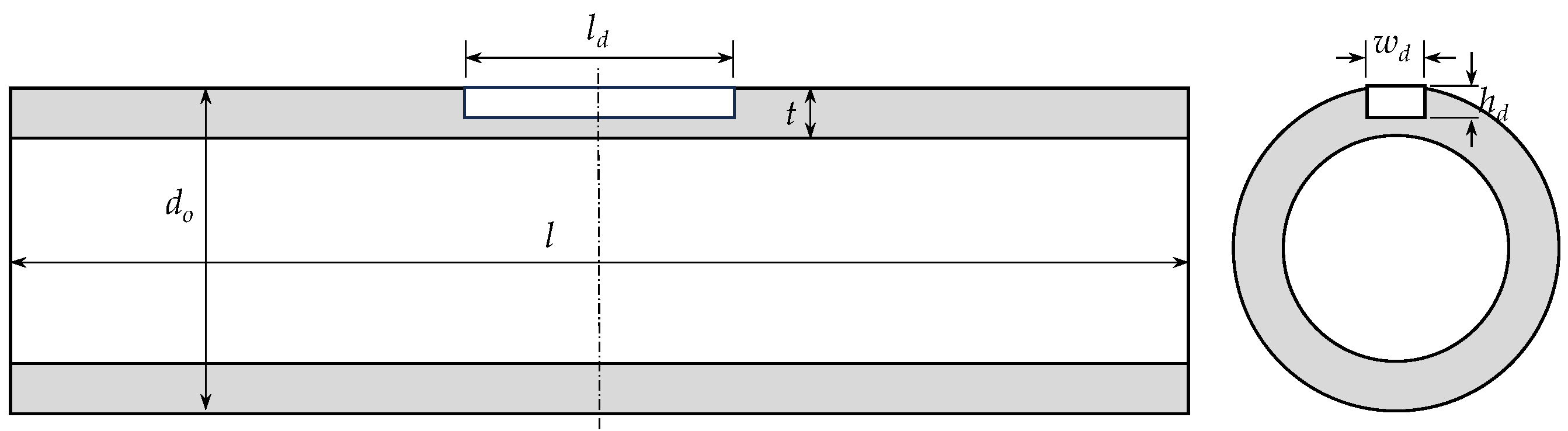
Each test pipe contained a machined axial defect characterized by its length, width, and depth (Figure 2). The width was fixed at 10 mm, whereas the length and depth varied. Therefore, defect width cannot explain the differences among the observed modes, and its independent effect was not evaluated. During each test, the pipeline was filled with the target medium, either pure CO2 or a CO2/N2 mixture, and then pressurized to the specified initial pressure. The initial pressure and temperature reported in this paper correspond to the conditions immediately before rupture. Because the temperature was not completely uniform along the main pipe, the averaged value is used as the representative initial temperature.
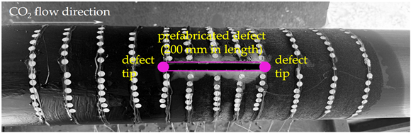
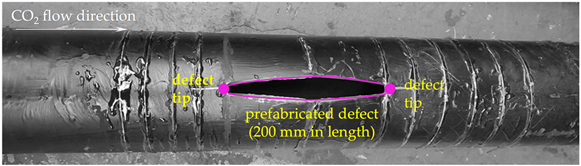
After each burst test, the failed pipe section was recovered and the post-test macroscopic rupture morphology was documented. The following features were identified from the experimental observations and post-test photographs: the initial leakage location, whether secondary crack initiation occurred at the defect tip, the dominant crack propagation direction, the axial extension length where measurable, whether the crack arrested, and the final rupture morphology. These observations form the basis for the morphology-based classification presented in Section 3 and Section 4.

2.2. Test Matrix and Limitations of the Conditions

Table 1 summarizes the nine tests, which covered pure CO2 and CO2/N2 mixtures, initial pressures of 8.2–11.6 MPa, temperatures of 28.5–40.1 °C, three pipe materials, and different pipe and defect geometries. The approximate initial CO2 inventory ranged from 72.63 to 154.20 kg.
To compare defects in pipes of different thicknesses, Table 1 includes the defect-depth ratio hd/t, residual-thickness ratio (thd)/t, and nominal hoop stress based on the original wall thickness. These parameters describe defect severity and global pressure loading but do not represent the dynamic local stress state at the machined defect.
The ratio hd/t did not uniquely separate the four modes. Test ② exhibited Mode II at hd/t = 0.853, whereas Tests ⑦ and ⑧ exhibited Modes I and IV at the higher ratios of 0.906 and 0.923, respectively. Test ⑨ exhibited Mode IV at hd/t = 0.692, further indicating that hd/t alone does not determine the rupture mode. Material grade also cannot be related independently to mode because the corresponding geometry, fluid composition, pressure, temperature, and main-pipe length differed, and dynamic fracture-resistance data were unavailable. A formal statistical correlation was not considered reliable because the database contains only nine tests, the outcome is categorical, the mode groups are small and unbalanced, and the explanatory variables are coupled. Therefore, only a qualitative cross-comparison is presented.
The test matrix was therefore not a single-variable program, and the mode differences cannot be attributed uniquely to defect severity, material, pressure, or main-pipe length. In particular, the distribution of Modes I, IV, and IV in Tests ⑦–⑨ cannot be interpreted as a direct effect of the longer main pipe. The present study consequently focuses on morphology classification rather than parameter–mode prediction. Additional main-pipe lengths may be considered in future controlled tests, but their independent effect cannot be quantified from the present database.

3. Results

Table 2, Table 3, Table 4 and Table 5 summarize the post-test morphologies of the nine pipes. Although all tests initiated at the prefabricated defect, their subsequent crack paths, propagation distances, arrest behaviors, and final openings differed markedly.

3.1. Common Feature: Initial Leakage Controlled by Prefabricated Defect

A common feature in all nine burst tests was that the initial leakage occurred in the middle region of the prefabricated axial defect. Before large-scale tearing or visible crack extension developed, the remaining ligament at the defect was penetrated or locally opened, forming the first CO2 release path. This confirms that the machined defect acted as the weakest region of the test pipe and effectively controlled the initial failure location.
Because the initial leakage location was essentially the same in all tests, the differences in final rupture morphology should mainly be attributed to the subsequent crack evolution rather than to variations in the initial failure position. The key distinctions are whether secondary cracks initiated from the defect tips, whether the crack propagated axially or circumferentially, whether it arrested, and how the pipe wall finally opened.

3.2. Classification Criteria for the Four Rupture Modes

Before introducing the individual rupture modes, the classification criteria are defined based on the post-test macroscopic observations. The classification does not rely on the final opening shape alone. Instead, each test is evaluated according to the following features:
(1)
Initial leakage location: whether the first visible leakage or local opening occurred in the middle region of the prefabricated axial defect;
(2)
Secondary crack initiation: whether additional cracks initiated from one or both tips of the prefabricated defect after initial leakage;
(3)
Dominant crack path: whether the subsequent tearing was mainly axial, circumferential, or axial followed by circumferential;
(4)
Axial crack-extension length: the measurable extension from the defect tips, when such extension could be identified from the recovered pipe;
(5)
Crack-arrest or instability behavior: whether the crack arrested after limited propagation or continued to full-bore fracture and structural instability;
(6)
Final macroscopic morphology: including plate-like unfolding, fish-mouth-shaped opening, and slit-like local opening.
On this basis, Mode I is defined as circumferential full-bore tearing without long-distance axial propagation; Mode II as sustained axial running followed by circumferential instability; Mode III as limited axial tearing followed by crack arrest; and Mode IV as leakage-dominated local opening without observable secondary crack propagation. These criteria are intended to improve the transparency and reproducibility of the morphology-based classification.

3.3. Mode I: Circumferential Full-Bore Tearing

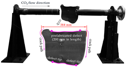
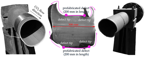
Mode I occurred in Tests ①, ③, and ⑦ (Table 2). After initial leakage at the defect center, secondary cracks initiated from the defect tips and propagated mainly circumferentially, with no obvious long-distance axial extension. The resulting full-bore fracture caused complete cross-sectional separation and plate-like wall unfolding. Thus, severe structural failure may occur without sustained axial running.

3.4. Mode II: Axial Running Followed by Circumferential Instability

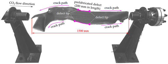
Mode II was observed only in Test ② and showed the strongest sustained axial propagation among the tested cases (Table 3). After leakage at the defect center, cracks propagated bilaterally from the defect tips. The total measurable axial extension was approximately 650 mm before the fracture transitioned to circumferential full-bore instability. No visible axial arrest occurred within the observable test section.
The 650 mm extension is specific to this DN100-scale specimen and is not a universal propagation threshold. Nevertheless, the morphology indicates that a similar response could develop into a longer running fracture in a full-scale pipeline if the coupled decompression and structural conditions remain favorable for continued tearing. Mode II is therefore treated as a conservative experimental case for crack-arrest assessment. Quantitative extrapolation to full-scale pipelines would additionally require consideration of pipe diameter, wall thickness, material resistance, fluid composition, decompression behavior, and crack velocity.

3.5. Mode III: Arrested Axial Tearing

Mode III occurred in Tests ④ and ⑤ (Table 4). Cracks initiated from both defect tips and propagated axially by approximately 245 and 310 mm, respectively, before arresting without circumferential full-bore fracture. Both pipes exhibited fish-mouth-shaped openings with outward wall deformation.
Fish-mouth morphology alone does not demonstrate axial propagation or arrest. In these tests, the classification is supported by secondary defect-tip initiation, measurable axial extension, and final termination of the cracks. The morphology is consistent with ductile tearing, crack-tip blunting, and plastic deformation, which may have contributed to arrest, although the crack-driving force and energy dissipation were not measured directly.

3.6. Mode IV: Leakage-Dominated Local Opening Without Crack Propagation

Mode IV occurred in Tests ⑥, ⑧, and ⑨ (Table 5). The remaining ligament opened locally to form a CO2 release path, but no clear secondary initiation or measurable crack extension from the defect tips was observed. The final openings were either locally fish-mouth-shaped or slit-like and remained confined to the original defect region. Therefore, the local fish-mouth feature in Mode IV indicates wall deformation and ligament opening, not an axially propagated crack that subsequently arrested.

3.7. Summary of Rupture Morphology Classification

Based on the post-test macroscopic morphologies, the nine burst tests were classified into four rupture modes, as summarized in Table 6. Although all tests showed initial leakage at the prefabricated axial defect, the subsequent crack evolution differed in secondary crack initiation, crack path, crack arrest behavior and final opening morphology.
The classification indicates that the rupture response of pre-defected CO2 pipes evolves progressively from local leakage to severe unstable fracture. Mode IV represents leakage-controlled local failure without crack propagation, whereas Mode II represents the most critical case observed in the present test series, characterized by sustained axial running before circumferential instability. Modes I and III correspond to intermediate but distinct behaviors: circumferential full-bore tearing and arrested axial tearing, respectively. This morphology-based classification provides a direct basis for discussing crack evolution and fracture arrest mechanisms in the following section.

4. Discussion

4.1. A Morphology-Based Crack Evolution Framework

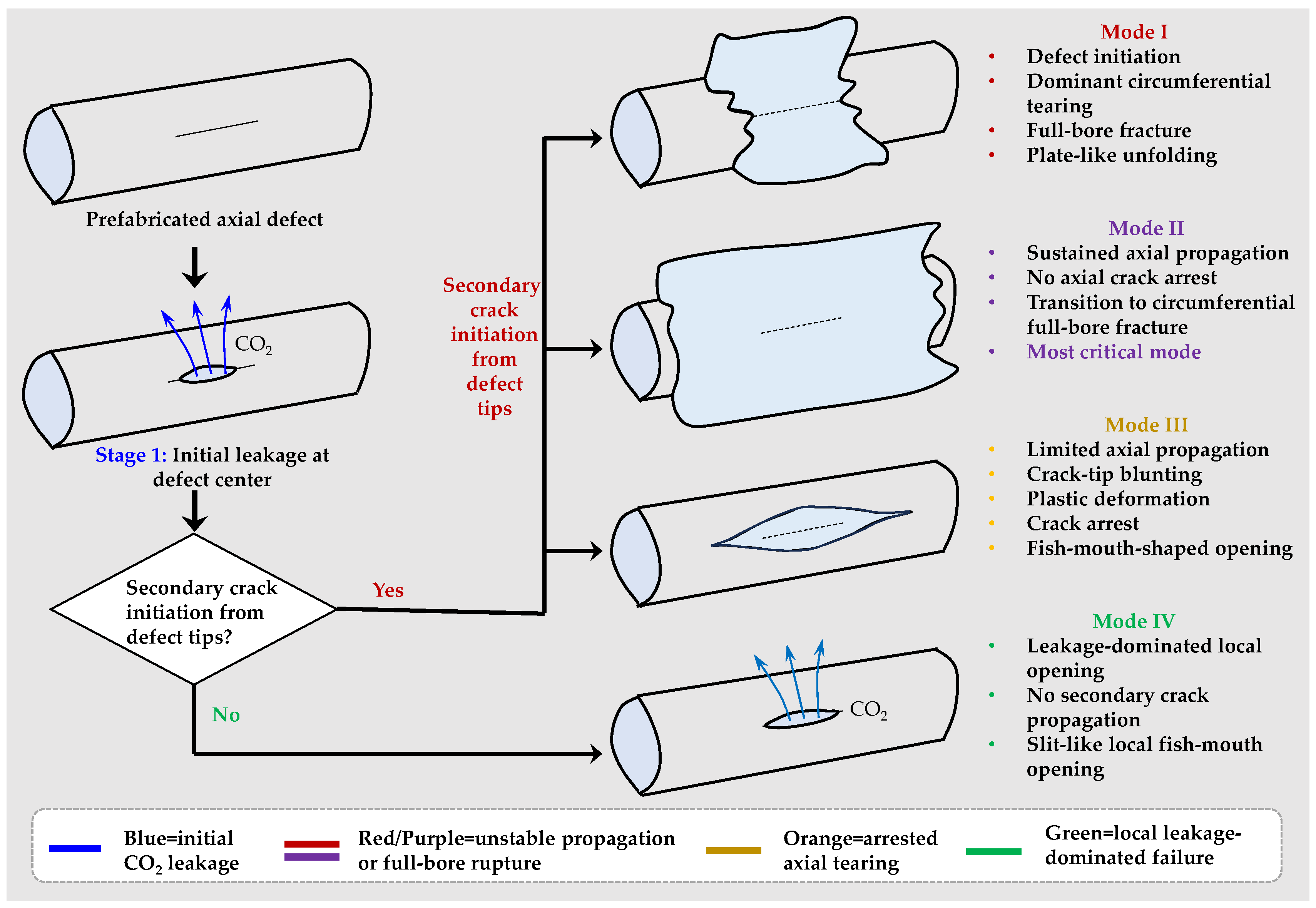
Based on the observations in Section 3.2, Section 3.3, Section 3.4, Section 3.5, Section 3.6 and Section 3.7, the rupture process of pre-defected CO2 pipes can be described using a morphology-based crack evolution framework, shown in Figure 3. Instead of treating the result simply as “propagation” or “arrest”, this framework divides the process into four sequential stages.
The first stage is local leakage at the prefabricated defect. In all tests, the initial failure occurred in the middle of the axial defect, where the residual ligament was thin and the local stress concentration was high. This stage formed the first CO2 release path.
The second stage is secondary crack initiation from the defect tips. After leakage, stress redistribution around the defect may promote cracking from the two defect ends if the remaining internal pressure, local stress concentration and transient decompression condition are sufficient. This behavior occurred in Modes I–III, whereas Mode IV stopped at the local leakage stage.
The third stage is crack path selection. Once secondary cracking occurs, the crack may propagate axially, turn into circumferential tearing, or first run axially and then transform into circumferential instability. Axial propagation is related to running fracture potential, whereas circumferential tearing is associated with full-bore rupture and severe wall opening.
The fourth stage is crack arrest or structural instability. If the effective crack-driving condition decreases sufficiently during decompression and local deformation, crack arrest may occur, potentially leaving a fish-mouth-shaped opening. Conversely, continued crack extension or full-bore fracture may occur when the combined fluid-loading and structural conditions remain favorable for tearing. In the present study, these interpretations are based on the observed rupture sequence and post-test morphology; the instantaneous crack-driving force and fracture resistance were not directly quantified. Thus, the final morphology records the competition among internal pressure loading, decompression behavior, local plastic deformation and fracture resistance.

4.2. Interpretation of Different Rupture Modes

Plate-like unfolding was mainly observed in Mode I and partly in Mode II after full- bore fracture. It indicates severe circumferential tearing and complete instability of the pipe cross-section. Once the circumferential crack propagated around the wall, the internal pressure and stored elastic energy caused the fractured pipe wall to open and flatten extensively. This morphology therefore represents high rupture severity and strong energy release.
Fish-mouth morphology had different meanings in Modes III and IV. In Mode III, it was accompanied by secondary defect-tip initiation, measurable axial extension, and final arrest. In Mode IV, it remained confined to the original defect and showed no measurable defect-tip extension. Fish-mouth morphology should therefore be treated as evidence of local ductile deformation, not as an independent criterion for propagation or arrest. Plate-like unfolding indicates full-bore instability, whereas a slit-like opening is associated with localized leakage.
The slit-like opening was mainly associated with Mode IV. In this case, the defect region acted primarily as a leakage channel, and the opening remained narrow and localized without axial or circumferential crack propagation. This morphology indicates that the force after leakage was insufficient to trigger secondary crack initiation, corresponding to the lowest rupture severity in the present test series.

4.3. Implications for Fracture Control and Crack Arrest Design

The results have three implications for fracture control. First, local leakage does not necessarily develop into a running crack, but the absence of axial running does not imply a mild consequence because circumferential tearing may still cause full-bore failure. Second, crack-arrest assessment should consider secondary initiation, crack path, extension, and final instability together rather than relying only on propagation distance or opening shape. Third, Mode II provides a conservative experimental case because sustained axial extension occurred without visible arrest before circumferential instability; however, its 650 mm extension is specimen-specific and not a full-scale design threshold.
The test matrix was not a single-variable program: the thermodynamic conditions, main-pipe length, test-pipe geometry, material grade, and defect geometry were partially coupled. In addition, only one specimen was tested for each nominal condition. Specimen-specific variability, including manufacturing tolerance, local wall-thickness variation, defect-machining accuracy, residual stress, material inhomogeneity, and dimensional deviation, may therefore have influenced the observed morphology. Consequently, the effects of the prescribed test variables cannot be separated from specimen-specific variability, and the four modes should be regarded as observed morphology classes rather than statistically validated deterministic outcomes. Their reproducibility remains to be established through repeated tests under nominally identical conditions.

5. Conclusions

In this study, nine DN100-scale CO2 pipe burst tests with prefabricated axial defects were examined using a morphology-based analysis method. The main conclusions are as follows:
  • In all nine tests, initial leakage occurred in the middle of the prefabricated axial defect, after which the crack-evolution paths differed.
  • Four morphology modes were identified: circumferential full-bore tearing (Mode I), sustained axial running followed by circumferential instability (Mode II), limited axial tearing followed by arrest (Mode III), and leakage-dominated local opening without observable secondary crack propagation (Mode IV).
  • Mode II showed the strongest sustained axial propagation among the tested cases, with a total measurable extension of approximately 650 mm before circumferential instability. This specimen-specific result provides a conservative case for crack-arrest assessment but is not a full-scale propagation threshold.
  • Fish-mouth morphology alone does not demonstrate axial propagation or arrest. In Mode III, it was accompanied by secondary defect-tip initiation and measurable axial extension; in Mode IV, the local fish-mouth-shaped or slit-like opening remained confined to the original defect.
  • Because the test variables were coupled and only one specimen was tested per nominal condition, the identified modes are qualitative observations within the tested range rather than deterministic parameter–mode relationships. Repeated, independently controlled tests are required to assess reproducibility and individual parameter effects.

Author Contributions

Conceptualization, X.Y. and L.C.; methodology, X.Y., J.Y. and L.C.; formal analysis, L.S.; investigation, X.W.; resources, X.W.; data curation, Y.W.; writing—original draft preparation, L.S.; writing—review and editing, Z.L. and X.Y.; visualization, Y.W.; supervision, J.Y.; project administration, X.Y. and L.C.; funding acquisition, X.Y. All authors have read and agreed to the published version of the manuscript.

Funding

This research was funded by the Sinopec Technology Development Project ‘Suitability Assessment and Performance Optimization of Pipeline Materials for Dense-Phase CO2 Transportation’ under grant No. 325011.

Data Availability Statement

The data supporting the findings of this study are available from the corresponding author upon reasonable request.

Acknowledgments

The authors thank the NIST Standard Reference Data support team for assistance with the REFPROP database acquisition process.

Conflicts of Interest

Authors Lei Shi, Xiaolin Wang and Yuxin Wang were employed by the SINOPEC Dalian Research Institute of Petroleum and Petrochemicals Co., Ltd. The remaining author declares that the research was conducted in the absence of any commercial or financial relationships that could be construed as a potential conflict of interest.

Abbreviations

The following abbreviations are used in this manuscript:
DNDiameter of nominal
NISTNational Institute of Standards and Technology
REFPROPReference Fluid Thermodynamic and Transport Properties Database
ASTMInternational Association for Testing Materials

References

  1. Liu, D.; Wang, S.; Liu, C.; Wang, W.; Chen, Z.; Chen, S.; Zhang, S.; Du, S.; Hong, B. Advancements in CO2 pipeline transportation technology: A bibliometric analysis and knowledge mapping study. Fuel 2026, 407, 137498. [Google Scholar] [CrossRef] [Scilit]
  2. Lu, H.; Ma, X.; Huang, K.; Fu, L.; Azimi, M. Carbon dioxide transport via pipelines: A systematic review. J. Clean. Prod. 2020, 266, 121994. [Google Scholar] [CrossRef] [Scilit]
  3. Munkejord, S.T.; Hammer, M.; Løvseth, S.W. CO2 transport: Data and models—A review. Appl. Energy 2016, 169, 499–523. [Google Scholar] [CrossRef] [Scilit]
  4. El-Kady, A.H.; Amin, M.T.; Khan, F. Analysis of CO2 pipeline regulations from a safety perspective for offshore carbon capture, utilization, and storage (CCUS). J. Clean. Prod. 2024, 439, 140734. [Google Scholar] [CrossRef] [Scilit]
  5. Tan, J.; Xin, Y.; Liu, W.; Jing, Y.; Hu, H. Progress on the leakage and diffusion characteristics of CO2 pipeline. Fuel 2026, 425, 139474. [Google Scholar] [CrossRef] [Scilit]
  6. Song, S.; Yu, J.; Li, Y.; Chen, H.; Liu, D.; Shan, X.; Chen, H.; Yao, H.; Shi, B.; Gong, J. Investigation of hydrate inhibitor tracking in oil-gas-water multiphase flow pipelines. Pet. Sci. 2026, 23, 3616–3633. [Google Scholar] [CrossRef] [Scilit]
  7. Hao, Y.; Song, S.; Guo, J.; Shan, L.; Chen, H.; Wei, S.; Jin, F.; Lu, Y.; Li, C.; Shi, B.; et al. Efficient and physically consistent transient modeling of gas flows in pipelines. Phys. Fluids 2026, 38, 076118. [Google Scholar] [CrossRef] [Scilit]
  8. Yu, X.; Liu, G.; Rao, S.; Fan, X.; Li, Y.; Hu, Q.; Wang, C.; Zhang, L.; Chen, Z. A critical review on corrosion challenges and prospects in supercritical offshore CO2 pipelines. J. Pipeline Sci. Eng. 2025, 2025, 100401. [Google Scholar] [CrossRef] [Scilit]
  9. Wang, Y.; Guo, Y.; Hu, Q.; Zhao, X.; Meng, L.; Yin, B.; Zhang, L.; Li, Y. A novel numerical model for simulating dynamic pipeline fracture propagation in CO2 considering complex decompression behavior. Process Saf. Environ. Prot. 2025, 203, 107864. [Google Scholar] [CrossRef] [Scilit]
  10. Botros, K.K.; Geerligs, J.; Rothwell, B.; Robinson, T. Measurements of decompression wave speed in binary mixtures of carbon dioxide and impurities. J. Press. Vessel Technol. 2017, 139, 021301. [Google Scholar] [CrossRef] [Scilit]
  11. Botros, K.K.; Geerligs, J.; Rothwell, B.; Carlson, L.; Fletcher, L.; Venton, P. Transferability of decompression wave speed measured by a small-diameter shock tube to full size pipelines and implications for determining required fracture propagation resistance. Int. J. Press. Vessel. Pip. 2010, 87, 681–695. [Google Scholar] [CrossRef] [Scilit]
  12. Botros, K.K.; Geerligs, J.; Eiber, R.J. Measurement of decompression wave speed in rich gas mixtures at high pressures (370 bars) using a specialized rupture tube. J. Press. Vessel Technol. 2010, 132, 051303. [Google Scholar] [CrossRef] [Scilit]
  13. Gu, S.; Li, Y.; Teng, L.; Hu, Q.; Zhang, D.; Ye, X.; Wang, C.; Wang, J.; Iglauer, S. A new model for predicting the decompression behavior of CO2 mixtures in various phases. Process Saf. Environ. Prot. 2018, 120, 237–247. [Google Scholar] [CrossRef] [Scilit]
  14. Botros, K.K.; Geerligs, J.; Rothwell, B.; Robinson, T. Measurements of decompression wave speed in pure carbon dioxide and comparison with predictions by equation of state. J. Press. Vessel Technol. 2016, 138, 031302. [Google Scholar] [CrossRef] [Scilit]
  15. Aursand, E.; Aursand, P.; Hammer, M.; Lund, H. The influence of CO2 mixture composition and equations of state on simu-lations of transient pipeline decompression. Int. J. Greenh. Gas. Control 2016, 54, 599–609. [Google Scholar] [CrossRef] [Scilit]
  16. Dall’Acqua, D.; Terenzi, A.; Leporini, M.; D’Alessandro, V.; Giacchetta, G.; Marchetti, B. A new tool for modelling the de-compression behaviour of CO2 with impurities using the Peng-Robinson equation of state. Appl. Energy 2017, 206, 1432–1445. [Google Scholar] [CrossRef] [Scilit]
  17. Bicelli, G.; Libero, G.; Picchi, D. Fracture susceptibility and depressurization dynamics in CO2 pipelines under uncertainty. Fuel 2026, 344, 140013. [Google Scholar] [CrossRef] [Scilit]
  18. Elshahomi, A.; Lu, C.; Michal, G.; Liu, X.; Godbole, A.; Venton, P. Decompression wave speed in CO2 mixtures: CFD modelling with the GERG-2008 equation of state. Appl. Energy 2015, 140, 20–32. [Google Scholar] [CrossRef] [Scilit]
  19. Qi, W.; Yu, T.; Li, L.; Chen, B.; Tang, C.; Xu, M.; Xiao, H. Research on ductile fracture arrest control of CO2 transportation pipelines in carbon capture, utilization and storage technology. Int. J. Press. Vessel. Pip. 2026, 222, 105840. [Google Scholar] [CrossRef] [Scilit]
  20. Aursand, E.; Dumoulin, S.; Hammer, M.; Lange, H.I.; Morin, A.; Munkejord, S.T.; Nordhagen, H.O. Fracture propagation control in CO2 pipelines: Validation of a coupled fluid–structure model. Eng. Struct. 2016, 123, 192–212. [Google Scholar] [CrossRef] [Scilit]
  21. Nordhagen, H.O.; Munkejord, S.T.; Hammer, M.; Gruben, G.; Fourmeau, M.; Dumoulin, S. A fracture-propagation-control model for pipelines transporting CO2-rich mixtures including a new method for material-model calibration. Eng. Struct. 2017, 143, 245–260. [Google Scholar] [CrossRef] [Scilit]
  22. Mokhtari, M.; Melchers, R.E. Next-generation fracture prediction models for pipes with localized corrosion defects. Eng. Fail. Anal. 2019, 105, 610–626. [Google Scholar] [CrossRef] [Scilit]
  23. Wang, Y.; Hu, Q.; Yin, B.; Zhao, X.; Meng, L.; Zhu, J.; Ouyang, X.; Li, Y. Research progress on dynamic crack propagation and crack arrest models of supercritical and dense-phase CO2 pipelines. J. Pipeline Sci. Eng. 2025, 5, 100255. [Google Scholar] [CrossRef] [Scilit]
  24. Skarsvag, H.L.; Hammer, M.; Munkejord, S.T.; Log, A.M.; Dumoulin, S.; Gruben, G. Towards an engineering tool for the prediction of running ductile fractures in CO2 pipelines. Process Saf. Environ. 2023, 171, 667–679. [Google Scholar] [CrossRef] [Scilit]
  25. Keim, V.; Paredes, M.; Nonn, A.; Munstermann, S. FSI-simulation of ductile fracture propagation and arrest in pipelines: Comparison with existing data of full-scale burst tests. Int. J. Press. Vessel. Pip. 2020, 182, 104067. [Google Scholar] [CrossRef] [Scilit]
  26. Liu, Z.; Qiao, F.; Yu, S.; Li, L.; Yan, X.; Yu, J.; Shi, L.; Wang, X.; Chen, L. Experimental investigation of fracture response and decompression behavior of DN150 X65 pipe subjected to near-critical CO2 release. Fuel 2027, 428, 140591. [Google Scholar] [CrossRef] [Scilit]
  27. Chen, L.; Yang, W.; Zhou, J.; Liu, Z.; Lv, Z.; Hu, Y.; Li, J.; Yan, X.; Yu, J.; Chen, S. Experimental investigation on full-scale fracture behavior and dynamic response of supercritical CO2 pipelines with N2 impurities. Int. J. Press. Vessel. Pip. 2026, 221, 105741. [Google Scholar] [CrossRef] [Scilit]

Figure 1. Schematic diagram of burst test facility.
Processes 14 02830 g001
Figure 2. Schematic diagram of test pipe and axial defect at the pipe wall.
Processes 14 02830 g002
Figure 3. Morphology-based crack evolution framework for pre-defected CO2 pipes.
Processes 14 02830 g003
Table 1. Test conditions of all nine tests.
Test Number
Main
pipe
Outer diameter Do/mm114.3114.3114.3114.3114.3114.3114.3114.3114.3
Wall thickness δ/mm888888888
Total length L/m17171717171726.526.526.5
MediumPure CO2Pure CO2Pure CO298%CO2
+2%N2
97%CO2
+3%N2
96%CO2
+4%N2
Pure CO2Pure CO2Pure CO2
Initial pressure P0/MPa8.89.310.911.610.69.88.28.49.7
Initial temperature T0 (1)/°C35.540.13332323328.536.530
Initial density ρ0 (2)/(kg/m3)642.24562.97764.36748.55696.32604.24740.61538.61766.72
Initial mass m (3)/kg82.8672.6398.6296.5889.8477.96148.95108.32154.20
Test
pipe
Outer diameter do/mm110.3108.3110.7110.3110.3110.66112.9112.7112.7
Thickness t/mm434.2444.185.35.25.2
Length l/m3333332.52.52.5
Material20# (4)X52X52X52X52X52X65X65X65
Defect length ld/mm300200200200200200200130200
Defect width wd/mm101010101010101010
Defect depth hd/mm2.82.563.123.103.062.84.84.83.6
Residual thickness (t − hd)/mm1.20.441.080.90.941.380.50.41.6
Defect depth ratio hd/t0.7000.8530.7430.7750.7650.6700.9060.9230.692
Residual thickness ratio (t − hd)/t0.30.1470.2570.2250.2350.3300.0940.0770.308
Nominal hoop stress σθ at wall
thickness/MPa; σθ = P0·(d0t)/(2t)
116.9163.2138.2154.1140.8124.883.286.8100.3
Morphology class and mode (5)IIIIIIIIIIIVIIVIV
(1): Normally, temperature varies along the main pipe. Here the averaged value is used. (2): Density is obtained from Reference Fluid Thermodynamic and Transport Properties Database (REFPROP) purchased from National Institute of Standards and Technology (NIST). (3): Mass is just an approximate value due to that temperature varies along the main pipe. (4): 20# steel in Chinese is equivalent to International Association for Testing Materials (ASTM) 1020 steel in the United States. (5): This row presents the experimental results; the detailed meaning can be found in Section 3 and Section 4.
Table 2. Post-test macroscopic rupture morphologies and crack-evolution features of Tests ①, ③, and ⑦ corresponding to Mode I: circumferential full-bore tearing.
Test NumberRupture Morphology
Processes 14 02830 i001
Processes 14 02830 i002
Processes 14 02830 i003
Table 3. Post-test macroscopic rupture morphology and crack-evolution sequence of Test ② corresponding to Mode II: sustained axial running followed by circumferential instability.
Test NumberRupture Morphology
Processes 14 02830 i004
Table 4. Post-test macroscopic rupture morphologies and crack-arrest features of Tests ④ and ⑤ corresponding to Mode III: arrested axial tearing.
Test NumberRupture Morphology
Processes 14 02830 i005
Processes 14 02830 i006
Table 5. Post-test macroscopic rupture morphologies of Tests ⑥, ⑧, and ⑨ corresponding to Mode IV: leakage-dominated local opening without observable secondary crack propagation.
Test NumberRupture Morphology
Processes 14 02830 i007
Processes 14 02830 i008
Processes 14 02830 i009
Table 6. Summary of rupture morphology modes.
ModeMode IMode IIMode IIIMode IV
Tests①, ③, ⑦④, ⑤⑥, ⑧, ⑨
Initial leakage locationMiddle region of the prefabricated axial defectMiddle region of the prefabricated axial defectMiddle region of the prefabricated axial defectMiddle region of the prefabricated axial defect
Secondary crack initiationInitiation from defect tipsInitiation from defect tipsInitiation from defect tipsNo obvious secondary initiation from defect tips
Dominant crack pathDominant circumferential tearing; no obvious long-distance axial propagationSustained bilateral axial propagation, followed by circumferential tearingLimited axial propagation from the defect endsNo axial or circumferential crack propagation; failure confined to defect region
Crack arrest behaviorNo arrest before full-bore fractureNo axial crack arrest before final instabilityAxial cracks arrested after limited extensionArrest at the initial/local opening stage
Final rupture morphologyFull-bore circumferential fracture with plate-like unfolding of the pipe wallLong axial crack extension and final full-bore fractureFish-mouth-shaped opening accompanied by measurable axial crack extension and subsequent arrestLocal fish-mouth-shaped or slit-like opening confined to the defect region
Main implicationStrong circumferential instability after local leakageStrongest sustained crack propagation capability in this test seriesLimited axial tearing followed by crack arrest; interpretation supported by defect-tip crack extensionLeakage-dominated local opening; fish-mouth morphology alone does not indicate crack propagation or arrest
Disclaimer/Publisher’s Note: The statements, opinions and data contained in all publications are solely those of the individual author(s) and contributor(s) and not of MDPI and/or the editor(s). MDPI and/or the editor(s) disclaim responsibility for any injury to people or property resulting from any ideas, methods, instructions or products referred to in the content.