Review

A Review of Internal Flow Fields in High-Pressure Common Rail Injector Nozzles
1
Marine Engineering College, Dalian Maritime University, Dalian 116026, China
2
School of Mechanical Engineering, Dalian University of Technology, Dalian 116024, China
3
Party Committee (President’s) Office, Binzhou Polytechnic University, Binzhou 256600, China
4
Industrial and Information Technology Development Service Center of Yanzhou District, Jining 272000, China
5
Hudong Zhonghua Shipbuilding (Group) Co., Ltd., Shanghai 200129, China
*
Author to whom correspondence should be addressed.
†
These authors contributed equally to this work.
Processes 2026, 14(17), 2757; https://doi.org/10.3390/pr14172757
Submission received: 7 July 2026 / Revised: 25 August 2026 / Accepted: 26 August 2026 / Published: 28 August 2026

Abstract

High-pressure common rail injector nozzles are key components of the fuel-injection system in modern diesel engines. The internal flow state and nozzle-exit flow characteristics directly affect fuel atomization, fuel–air mixing, and combustion performance. This article adopts a structured qualitative review method to analyze the research progress on the internal flow of high-pressure common rail injector nozzles. The existing research can be summarized into five directions: the influence of nozzle structure and operating parameters, non-circular nozzle structure, visualization experimental research, the influence of fuel properties, and artificial-intelligence-assisted optimization. The results show that nozzle geometry, injection conditions, fuel properties, cavitation evolution, and turbulence characteristics are the key factors affecting the internal flow behavior. However, current research still faces problems such as insufficient multi parameter coupling mechanisms, limited experimental verification under actual working conditions, uncertainty in numerical models, and insufficient generalization ability of artificial intelligence models. Based on the above analysis, future research needs to further develop high-precision multi physics simulation methods, advanced visualization technologies, and multi-objective intelligent optimization strategies to enhance the understanding of the mechanism and optimization design level of high-pressure common rail injectors.

1. Introduction

High-pressure common rail injectors are critical components in modern diesel fuel injection systems, where the internal flow behavior of the nozzle directly dictates fuel atomization, fuel–air mixing, and combustion processes [1,2]. Under high-pressure injection conditions, intense flow separation, turbulent fluctuations, and cavitation occur within the orifice. These complex flow dynamics not only affect the discharge coefficient and orifice exit velocity but also further alter spray breakup, droplet distribution, and the risk of cavitation erosion [3,4,5,6]. Consequently, the internal flow field of the nozzle has become a key scientific issue in the optimization of high-pressure common rail injection systems [7].
Extensive investigations have been conducted regarding orifice geometry, injection pressure, back pressure, needle lift, fuel properties, optical visualization, and numerical simulations. Representative studies have demonstrated measurable improvements in injector internal flow characteristics through structural optimization. For example, Zhang et al. [8] have reported that an optimized nozzle design increased the exit mass flow rate by 21.19% and reduced the fuel vapor volume by 81.38% when compared with the baseline nozzle under specific operating conditions. Furthermore, recent artificial intelligence-based approaches have shown promising capability for injector performance prediction, with some studies achieving prediction errors below 5% for injection-related parameters. However, these improvements and prediction accuracies remain highly dependent on nozzle geometry, operating conditions, fuel properties, and modeling approaches. [9,10]. In particular, there is still a lack of unified reviews and comparisons on the coupling relationships among nozzle geometry, operating parameters, internal flow fields, and spray atomization, as well as on topics including CFD validation, experimental uncertainties, and artificial intelligence (AI)-assisted optimization [11,12,13,14,15,16]. Therefore, focusing on the internal flow field characteristics of high-pressure common rail injector nozzles, this paper systematically reviews and analyzes the current research progress, primary limitations, and future research directions.
In recent years, advances in computational fluid dynamics (CFD), optical visualization experiments, and artificial intelligence methods have expanded the research methodologies for investigating the complex internal flow processes within injector nozzles [17]. CFD simulations provide detailed insights into the pressure fields, velocity fields, turbulence structures, and cavitation distribution within the orifice. However, their results are highly sensitive to mesh resolution, time steps, boundary conditions, and the selection of turbulence and cavitation models, leaving significant uncertainties—particularly regarding transient needle motion, multiphase transitions, and cavity collapse [18,19,20]. In contrast, optical diagnostic methods such as high-speed imaging and particle image velocimetry (PIV) can directly observe cavitation morphology, flow regime transitions, and spray development processes, providing a crucial basis for numerical model validation. Nevertheless, due to the material strength limitations of transparent nozzles, scale-up effects, optical distortion, and test pressure constraints, discrepancies may still exist between optical results and the actual behavior of actual-size metal nozzles [21,22]. Consequently, the relationship between CFD and optical experiments is not merely complementary; rather, it involves inherent contradictions between model assumptions and experimental measurability, as well as between local flow details and the reproducibility of actual operating conditions.
On this basis, AI methods have increasingly been applied to the prediction of nozzle flow fields and geometric optimization. They primarily serve to establish mapping relationships among nozzle geometry, operating parameters, flow field features, and spray characteristics using existing experimental, numerical, or engine bench data [23]. This facilitates the rapid prediction of metrics such as injection quantity, injection rate, discharge coefficient, cavitation risk, spray penetration length, and spray cone angle. When compared with CFD and optical experiments, AI methods focus more on extracting nonlinear correlations from data and improving the efficiency of multi-parameter prediction and optimization. However, their reliability strongly depends on training data quality, sample coverage, and validation strategies, while their generalizability to unseen orifice geometries, fuel types, or operating conditions requires further verification [24]. Therefore, the key methodological challenge currently facing nozzle flow field research is how to establish a reliable connection among the mechanistic analysis capabilities of CFD, the direct observation capabilities of optical experiments, and the rapid prediction capabilities of AI methods, and how to improve the comparability across different studies through unified boundary conditions, multi-metric validation, and uncertainty analysis.
However, the internal flow process of the high-pressure common rail injector is still affected by the coupling effects of many factors, such as cavitation, turbulence, liquid compressibility, needle valve transient motion and injection pressure fluctuation, and its flow mechanism and spray formation process are still very complex [25]. High-pressure common rail injectors control fuel delivery into the nozzle orifices through the transient opening and closing of the needle valve. Injection pressure, back pressure, needle lift, and injection timing serve as the primary boundary conditions for the internal nozzle flow, affecting the pressure distribution, cavitation development, turbulence intensity, and orifice exit velocity. Building upon this, this paper focuses on the internal flow field characteristics of high-pressure common rail injector nozzles. It systematically compares how nozzle geometry and operating parameters, non-circular orifices, different fuels, and AI optimization affect internal flow and spray characteristics, while also analyzing optical visualization alongside various research methods, key conclusions, and their applicable conditions. On this basis, it further summarizes the primary limitations and unresolved scientific issues in numerical simulations, experimental validations, and AI optimization, aiming to clarify current research progress, methodological differences, and future research directions.

2. Review Methodology

This paper adopts a structured qualitative review method and summarizes the research progress on the internal flow of high-pressure common rail injectors through a narrative synthesis approach. The purpose is to summarize the development trend of internal flow research in high-pressure common rail injectors through topic classification and mechanism analysis, rather than establishing fully reproducible evidence screening process based on systematic review or meta-analysis methods. Among these, “structured” refers to the organization and analysis of existing literature based on predefined research directions and unified comparative dimensions, while qualitative “means that this article mainly conducts research synthesis through mechanism analysis and trend summary, without conducting statistical quantitative integration or effect analysis.

2.1. Literature Search Strategy

To systematically review the research progress on the flow field characteristics of high-pressure common rail injector nozzles, this paper combines literature retrieval with thematic classification to search, screen, and categorize relevant domestic and international studies. The literature was primarily sourced from databases including Web of Science Core Collection, Scopus, ScienceDirect, CNKI, and Google Scholar. The search was conducted up to July 2026, with the publication timeframe primarily set between 2000 and 2026. Considering that the development history of high-pressure common rail systems, injector operating principles, and fundamental cavitation theories involve earlier studies, no strict time limits were imposed on representative classic literature. Furthermore, backward citation tracking was performed using the reference lists of the included papers to capture important studies potentially missed during the database search [26]. Given the substantial variations among existing studies in terms of nozzle geometries, boundary conditions, fuel types, data sources, model configurations, and evaluation metrics, this paper employs a structured qualitative review approach to summarize and compare the primary conclusions, applicable conditions, and limitations across various research directions.
The literature search centered on themes including internal flow, cavitation characteristics, orifice geometry, operating parameters, visualization experiments, fuel properties, and intelligent optimization of high-pressure common rail injector nozzles [27]. Primary search terms included “high-pressure common rail”, “common rail injector”, “diesel injector nozzle”, “nozzle internal flow”, “cavitation flow”, “turbulence”, “needle lift”, “injection pressure”, “back pressure”, “non-circular nozzle”, “elliptical nozzle hole”, “optical nozzle”, “flow visualization”, “spray characteristics”, “alternative fuel”, “machine learning”, “artificial intelligence”, and “nozzle optimization” [28]. During the retrieval process, Boolean operators such as “and” and “or” were used to combine these keywords according to the specific search rules of each database, thereby broadening the literature coverage while ensuring the relevance of the results to the scope of this review.

2.2. Literature Screening and Inclusion Criteria

The retrieved literature is initially screened based on the title and abstract, and full-text reading is conducted on literature that meets the research topic. Literature screening mainly considers the relevance of research objects, the degree of matching of research content, the reliability of research methods, and the completeness of result descriptions. The included literature mainly includes that on the flow process inside the high-pressure common rail injector and nozzle hole and the analysis of the flow field characteristics [29], cavitation behavior, and spray formation process inside the nozzle using numerical simulation, visual experiment, or intelligent prediction methods [30].
Literature exclusion mainly includes the following situations: Firstly, deleting duplicate literature included in different databases. Secondly, cases where correlation with the internal flow mechanism of the high-pressure common rail injector is weak; where the fuel system, engine overall performance, combustion process, or emission characteristics are analyzed; and where the research on the internal flow and spray formation mechanism of the injector is not involved. Finally, cases where the literature lacks a sufficient description of research subjects, model parameters, experimental conditions, or main results to support comparative analysis between different studies is not the focus of this article.

2.3. Literature Classification and Comprehensive Analysis Methods

This article selects peer-reviewed journal articles and related conference papers published in both Chinese and English as the main research objects. Duplicate literature is checked and deleted based on title, author, publication year, and DOI information, and the quality of the literature is evaluated by considering the relevance of the research content, the reliability of the methods, and the extractability of the results. Based on the differences in research objects and technical methods, this article summarizes relevant research into five main directions, including the influence of fuel injector structural parameters and operating conditions, special nozzle structure design, internal flow visualization experiments of nozzles, the influence of different fuel characteristics, and artificial-intelligence-assisted prediction and optimization research. For different types of literature, a focus was placed on comparing their research objects, adopted methods, working conditions, evaluation indicators, main research conclusions, and existing limitations.
During the comprehensive analysis, this review mainly compared the research objectives, commonly used methods, operating conditions, evaluation indicators, major findings, and existing limitations across different research areas. The internal flow characteristics mainly include pressure distribution, velocity field, turbulence development, and cavitation behavior, while the external spray characteristics mainly involve spray cone angle, spray penetration length, droplet breakup, gas-phase volume fraction, and air–fuel mixing processes [31]. Through the above classification and comparative analysis, the current limitations in high-pressure common rail injector flow field research were further summarized, including investigations under ultra-high-pressure realistic operating conditions, multi-parameter coupling effects, complex nozzle geometries, adaptability to alternative fuels, high-pressure optical visualization techniques, as well as the physical interpretability and generalization capability of artificial intelligence models. Based on these analyses, the future development trends of flow field studies in high-pressure common rail injector nozzles were discussed.

3. The Flow Field Characteristics of Injector Nozzles

3.1. Cavitation Effects

As high-pressure fuel flows through the needle seat and orifice inlet, local acceleration, flow separation, and vortices induce a rapid pressure drop; cavitation can occur within the nozzle when the local pressure falls below the saturated vapor pressure of the fuel. Depending on cavity morphology and evolution characteristics, common types of cavitation within the nozzle include bubbly, sheet, cloud, and string cavitation [32,33]. Their formation is strongly dependent on orifice geometry, needle motion, injection pressure, back pressure, and fuel properties, and it subsequently affects the discharge coefficient, exit velocity, spray breakup, and orifice cavitation erosion. This can lead to severe problems, particularly in applications requiring high flow velocities. The issue is highly pronounced in injector nozzles, where prolonged cavitation causes wear on the inner walls of the nozzle body and orifice passages, ultimately reducing the service life of the engine injectors [34].
Overall, cavitation has a dual effect on the flow of fuel injectors. Moderate cavitation can enhance outlet flow disturbance and turbulence and promote fuel fragmentation and atomization. Excessive cavitation will reduce the effective flow area, decrease the flow coefficient, and exacerbate flow fluctuations, pressure pulsations, and nozzle cavitation. Its impact is jointly constrained by the nozzle structure, needle valve lift, injection pressure, back pressure, and fuel properties [35,36]. Therefore, when evaluating the cavitation effect, the mass flow rate, flow coefficient, outlet velocity, turbulence intensity, spray characteristics and wall erosion risk should be comprehensively considered.

3.2. Research on Flow Field Characteristics of Injector Nozzles Under Structure and Operating Parameters

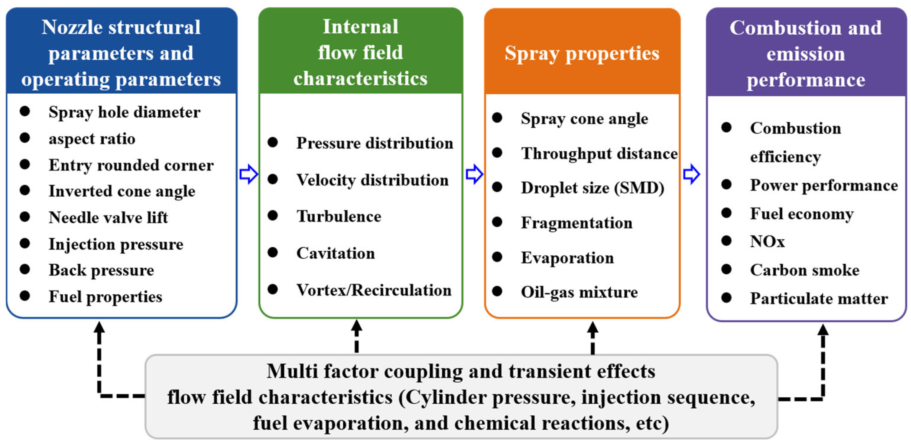
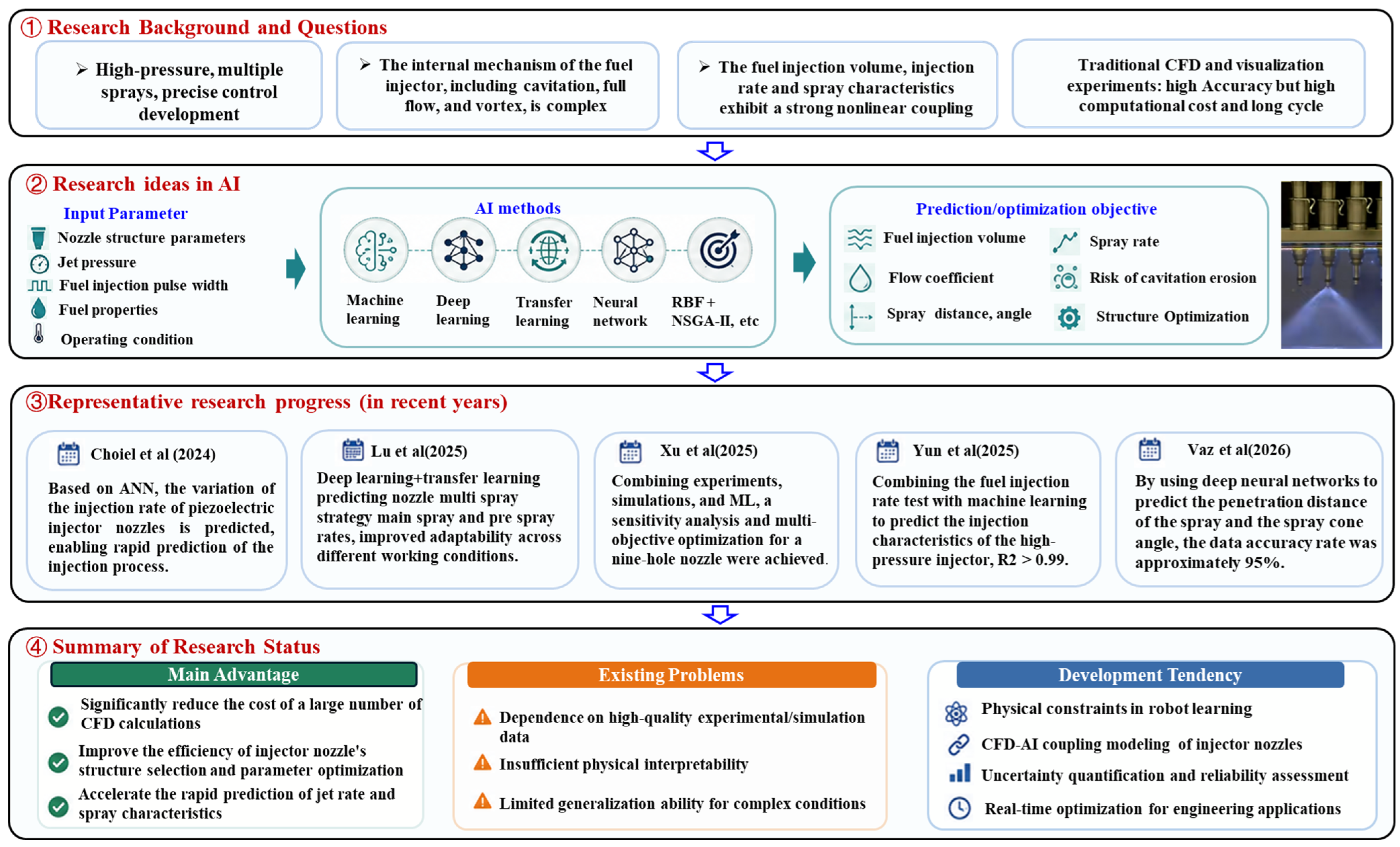
The internal flow field characteristics of the nozzle are closely related to nozzle geometry, operating parameters, and fuel properties. The parameters, such as orifice diameter, length-to-diameter ratio, inlet radius, taper angle, and needle lift, along with injection pressure, back pressure, and fuel properties, collectively determine the pressure and velocity distributions, turbulence intensity, cavitation evolution, and vortex/recirculation phenomena within the nozzle [37]. Complex correlations exist between the internal flow field and spray characteristics, which are further subjected to the coupled and transient effects of in-cylinder pressure, temperature, injection timing, air motion, fuel evaporation, and chemical reactions. Therefore, Figure 1 serves merely to outline the primary correlations among these factors, rather than indicating a strict unidirectional linear causal relationship.
Regarding the effects of an injector nozzle’s operating parameters on its flow field characteristics, Sun et al. [38] used a six-hole nozzle from a high-pressure common rail direct-injection diesel engine as the baseline model and employed a structured hexahedral mesh, with a grid spacing of 0.001 mm in the needle cone and orifice regions, resulting in a total of 132,988 mesh across the entire fluid domain. By adopting the k–ε turbulence model and the Schnerr–Sauer cavitation model, they conducted numerical simulations using ANSYS Fluent software to evaluate the effects of five fundamental parameters—pressure difference, inlet radius, orifice coefficient, length-to-diameter ratio, and inner wall roughness—on the internal fluid dynamics and cavitation characteristics. By analyzing key physical parameters such as mass flow rate, discharge coefficient, average vapor volume fraction, average exit velocity, and turbulent kinetic energy, they revealed the mechanisms underlying the formation, development, and collapse of cavitation within the nozzle. However, the numerical uncertainty in this study was not systematically quantified; therefore, the conclusions should be limited to the specific models and operating conditions. In addition, it was found that cavitation does not form in the nozzle unless the differential pressure reaches a certain value, which provides a basis for optimization of the nozzle design. Wang et al. [39], using the two-phase gas–liquid VOF turbulence model simulation of ANSYS Fluent software, found that the radius of curvature at the nozzle inlet and the inverted cone angle significantly affect the flow rate and atomization effect of the nozzle. The results show that increasing the radius of curvature increases the flow rate but decreases the fuel atomization while increasing the inverted cone angle facilitates atomization but decreases the fuel flow rate and mass flow rate. The best performance is achieved when the radius of curvature at the nozzle inlet is 0.1 mm, and the design should balance the relationship between atomization and flow rate to optimize nozzle performance. Under the nozzle geometry and simulated conditions employed in this study, an inlet radius of 0.1 mm yielded the optimal overall performance; however, this result should not be directly extrapolated to other injector geometries and operating conditions. Guo et al. [40] established a three-dimensional fuel flow simulation model to study the cavitation flow and cavitation wear in the injection holes of a diesel injector and the results show that increasing the radius of the inlet fillet of the injection holes can effectively reduce the cavitation wear, which mainly affects the inlet and upper side surfaces of the injection holes. In contrast, the influence of nozzle inclination angle and surface roughness is small, and the life of the injector can be significantly improved by adjusting the design parameters of the nozzle and increasing the radius of the inlet fillet. Predicting cavitation-induced material degradation typically involves three approaches: first, identifying potential erosion regions using CFD metrics such as vapor volume fraction, cavitation duration, and local pressure gradients; second, evaluating erosion intensity based on pressure pulses, wall impact energy, or erosion power generated by bubble collapse; and third, establishing empirical or fluid–structure interaction (FSI) models by incorporating material hardness, fatigue strength, and surface response. While current methods effectively identify high-risk erosion zones, the quantitative prediction of material loss rates remains constrained by cavitation models, spatiotemporal resolution, material properties, and experimental calibration data. Future studies must integrate transient flow computations, material response models, and cavitation erosion tests to enhance prediction reliability. These findings are not necessarily contradictory; rather, they emphasize different evaluation metrics, such as flow capacity, atomization, and cavitation erosion. Increasing the inlet corner radius mitigates flow separation and local pressure drops at the orifice inlet, thereby enhancing flow capacity and reducing the risk of cavitation erosion. However, the resulting attenuation of cavitation and turbulent perturbations can compromise primary fuel breakup under certain operating conditions. Therefore, optimizing the inlet corner radius requires striking a balance among flow capacity, atomization, and orifice durability.
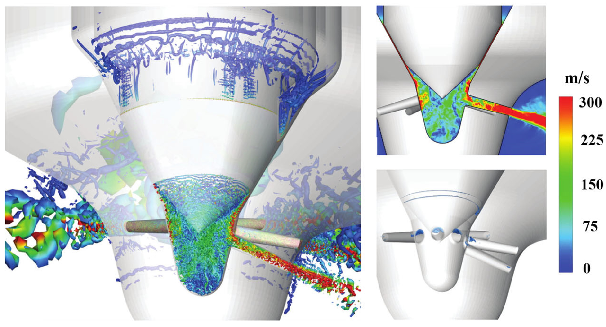
In addition, Zhang et al. [8] employed a coupled internal flow and spray model, an SVM surrogate model, and the NSGA-II algorithm to optimize the nozzle geometry. At an injection pressure of 80 MPa and a back pressure of 3 MPa, the optimized nozzle exhibited a 21.19% increase in exit mass flow rate and an 11.91% increase in spray penetration length compared with the baseline geometry. Concurrently, the fuel vapor volume and Sauter mean diameter (SMD) decreased by 81.38% and 1.37%, respectively. The model was validated against injection rate experiments, yielding a maximum deviation of 7.6%. However, because uncertainty intervals and system sensitivities were not reported, these results remain specific to the nozzle geometry, models, and operating conditions of that study. Moreover, the aforementioned studies employ varying injection pressures, back pressures, orifice dimensions, fuel temperatures, needle lifts, and numerical models. Some literature also fails to fully report pressure ratios, cavitation numbers, Reynolds numbers, and other essential parameters. Therefore, the difficulty in comparing existing studies originates from two aspects: differences in research conditions and methodologies and insufficient reporting of key parameters in some studies. The former limits direct comparison under unified conditions, whereas the latter affects the assessment of the reliability and applicability of reported conclusions. Örley et al. [41] simulated the transient multiphase flow within a 9-hole nozzle at 150 MPa, employing an immersed boundary method and an equation-of-state-based compressible two-phase two-component homogeneous mixture model. The results indicated that there are differences between the cavitation and turbulent flow inside the nozzle during the opening and closing stages of the needle valve. When the needle valve is opened, cavitation mainly occurs on the needle valve seat surface, and the mass flow rate at the nozzle outlet is minimally affected by cavitation; however, when the needle valve is closed, the collapse of the bubble will result in strong pressure waves, leading to cavitation, as shown in Figure 2. Similarly, due to variations among the aforementioned studies in injector geometries, pressure conditions, numerical models, and the treatment of needle motion, their results are only suitable for comparing general trends under their respective operating conditions.
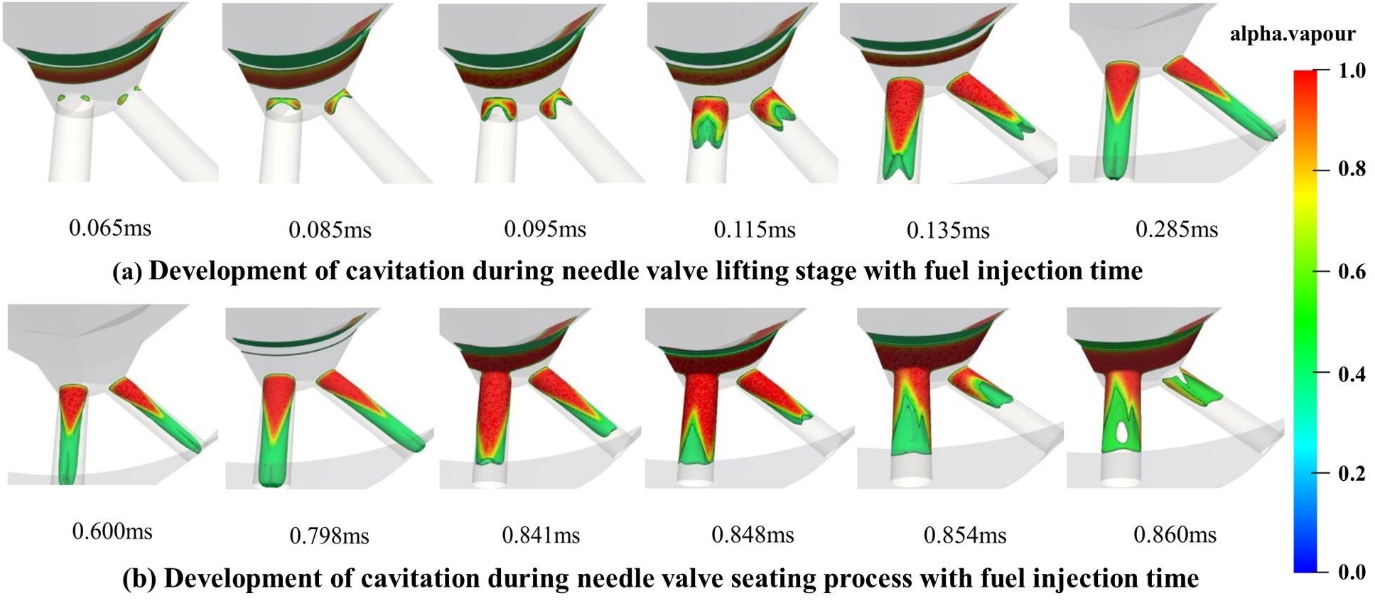
Based on a gas–liquid two phase flow model of fuel within the injector nozzle, Li [42] investigated the effects of structural and operating parameters on the internal flow and atomization characteristics at an inlet pressure of 160 MPa and a back pressure of 3 MPa. Increasing the orifice diameter increased the thickness and volume of the cavitation region. Shortening the orifice length improved spray performance but intensified cavitation and adversely affected flow performance, whereas increasing the back pressure suppressed cavitation development. Zhang et al. [43] experimentally investigated an ultra-high-pressure common rail injection system with a maximum rail pressure of 250 MPa and analyzed pressure fluctuations under different rail-pressure conditions. The results showed that increasing the rail pressure intensified the impact pressure wave generated by needle seating at the end of injection. Both the pressure drops and the pressure fluctuation amplitude during injection also increased with rail pressure. Wang [44] studied the cavitation process of the injector needle valve during the lifting and seating phases and its variation process with time, as shown in Figure 3. Numerical simulation results indicate that the cavitation region exhibits distinct transient evolution characteristics in conjunction with the movement of the needle valve during the fuel injection process. In the needle valve lifting stage, the increase of the injection time would cause the formation of geometrically induced cavitation at the entrance of the spray hole and rapidly extend along the surface of the spray hole to the exit into a sheet of cavitation, before ultimately reaching the exit of the spray hole to form a super-cavitation. In the needle valve seating stage, cavitation is first generated at the needle valve surface, and the cavitation at the needle valve surface gradually increases with time, while the cavitation in the spray hole gradually develops towards the hole with the seating of the needle valve, i.e., it flows back at the inlet of the spray hole.
In summary, the orifice diameter, length-to-diameter ratio, inlet corner radius, orifice taper, needle lift, injection pressure, and back pressure collectively affect cavitation, the discharge coefficient, and orifice exit flow characteristics by altering local pressure losses, flow separation, and vortex structures. As these parameters exert varying effects on flow capacity, atomization quality, and cavitation erosion risk, injector nozzle optimization should shift from single-parameter analysis toward evaluating multi-parameter coupling and making multi-objective trade-offs for comprehensive performance.

3.3. Research on Flow Field of the Injector Nozzle Under Non-Circular Structure

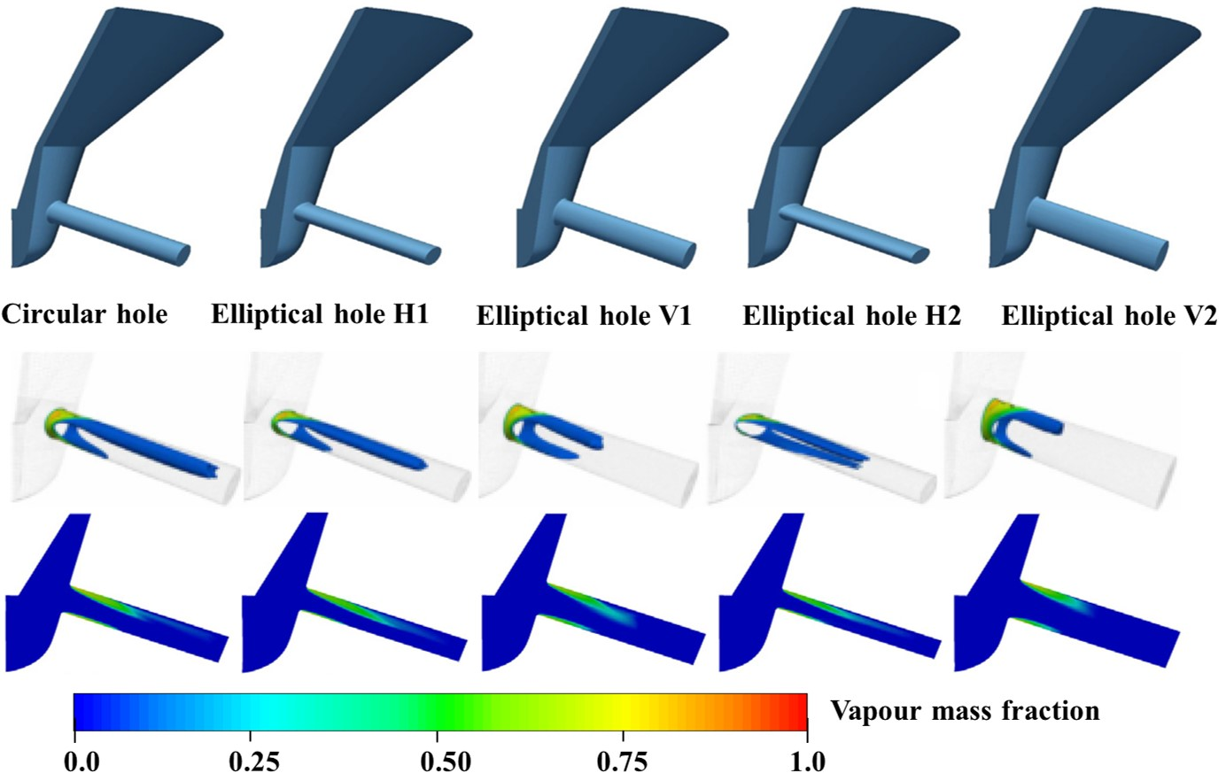
In the study of the flow field characteristics of the injector nozzle under the non-circular structure, many scholars have also carried out related research. Yin et al. [45] compared the spray characteristics of elliptical and circular orifices under evaporative conditions. The results indicated that elliptical orifices exhibit a shorter steady-state spray penetration length, which may help reduce wall impingement and improve fuel–air mixing in small combustion chambers. However, their ultimate impact on combustion and soot emissions remains dependent on the combustion chamber geometry and operating conditions. Zhang [46] found that under the investigated geometries and operating conditions, the transverse elliptical orifice exhibited weaker internal cavitation and a higher mass flow coefficient compared with the circular and longitudinal elliptical orifices. Additionally, the small-scale vortices formed at its bottom promoted string cavitation. Although this configuration demonstrates certain advantages in atomization and breakup, its comprehensive performance requires further evaluation based on metrics such as flow characteristics, cavitation erosion risk, manufacturability, and durability. Molina et al. [47] compared a circular orifice with four elliptical orifices while maintaining a constant exit cross-sectional area, as shown in Figure 4. Elliptical orifices with a vertical major axis are less prone to cavitation and yield a lower discharge coefficient, whereas those with a horizontal major axis exhibit more intense cavitation and a higher discharge coefficient. This finding differs from that of Zhang, a discrepancy likely stemming from differences in the definition of orifice orientation, relative inflow direction, aspect ratio, inlet rounding, L/D ratio, sac geometry, and boundary conditions. Therefore, the cavitation characteristics of elliptical orifices must be evaluated in the context of specific geometries and operating conditions. The aforementioned studies by Zhang and Molina et al. report differing conclusions regarding the cavitation intensity in elliptical orifices. This discrepancy is likely to be attributed to differences in how the elliptical axis orientation is defined and its arrangement relative to the upstream flow. Furthermore, variations in the orifice aspect ratio, inlet corner radius, orifice length, sac geometry, and boundary conditions can alter the inlet flow separation and local low-pressure regions. Therefore, the cavitation characteristics of elliptical orifices cannot be evaluated solely based on their cross-sectional orientation; they must be analyzed in conjunction with the specific nozzle geometry and inflow conditions.
Sa et al. [48] investigated the cavitation–turbulence coupling within a helical-grooved nozzle. The results indicated that the swirl induced by the helical groove intensifies cavitation inside the orifice and alters the turbulent core as well as the kinetic energy distribution at the exit. However, its ultimate impact on spray characteristics requires further verification. Leng et al. [49] employed a two-fluid model to compare the three-dimensional multiphase flow between circular and cross-shaped orifice nozzles. The cross-shaped orifice yields more gradual pressure and velocity variations along the axial direction, while generating a region of high turbulent kinetic energy near the exit, which potentially promotes fuel atomization. Zhang et al. [50] investigated the relationship between cavitating flow and cavitation erosion in multi-layer and tapered orifices, as illustrated in Figure 5. Their findings demonstrated that the upper-layer orifices are more susceptible to cavitation. Furthermore, the orifice conicity significantly affects evaporation, condensation, and cavitation erosion risks; for negative taper geometries, the high-risk regions are primarily concentrated at the orifice inlet and the inclined surfaces. These novel geometries regulate the internal flow through distinct mechanisms—swirl induction, intersecting passages, inter-layer flow distribution, and cross-sectional gradation. Currently, existing studies have yet to compare their flow performance, spray characteristics, manufacturability, and durability under unified boundary conditions.
Based on current research, non-circular orifices can modulate cavitation development and spray breakup by altering inlet flow separation, vortex structures, and exit velocity distributions. However, it remains difficult to identify a universally optimal non-circular orifice design. Different orifice geometries prioritize varying aspects of cavitation suppression, the discharge coefficient, and spray atomization. Their performance is influenced by factors such as the orifice aspect ratio, inlet corner radius, sac geometry, injection pressure, back pressure, and upstream inflow direction. According to reported findings, transverse elliptical orifices offer a favorable overall trade-off under certain operating conditions. Specifically, their relatively weak internal cavitation intensity helps mitigate the risks of excessive cavitation and erosion; meanwhile, they exhibit a higher mass discharge coefficient and can enhance spray breakup through their exit velocity distributions and vortex structures. Therefore, transverse elliptical orifices represent a promising configuration for non-circular nozzle optimization. Nevertheless, their advantages require further validation under identical boundary conditions, standardized evaluation metrics, and realistic injector operating conditions.

3.4. Research on Flow Field Characteristics of Injector Nozzles Under Visualization Experiment

Regarding visualization experiments on the internal flow field of fuel injectors, He et al. [51] constructed a transparent, scaled-up nozzle test rig to visualize the flow at the tip of a multi-hole injector nozzle and to validate results from 3D numerical simulations of cavitating flow. Their study further analyzed the relationships between cavitation inception conditions, discharge coefficients, and dimensionless cavitation parameters, as well as the effects of factors such as sac volume, inlet curvature, spray hole inclination, needle lift, and eccentricity on internal flow and cavitation distribution. It should be noted that results obtained from scaled-up transparent nozzles are applicable only to the specific scales and test conditions used; unless geometric similarity and matching dimensionless numbers—such as the Reynolds, Weber, and Euler numbers, as well as cavitation parameters—are simultaneously satisfied, the results should not be directly extrapolated to full-scale injectors. Watanabe et al. [52] combined transparent nozzles featuring needle head angles of 90°, 70°, and 30° with numerical simulations to investigate the effects of needle geometry on internal vortices, string cavitation, and spray characteristics. The results indicated that, under their experimental conditions, a smaller needle head angle suppressed internal vortices, leading to a more stable flow within the sac chamber and reduced fluctuations in the orifice exit mass flow rate; however, it also yielded a narrower spray cone angle and a longer spray penetration length. Furthermore, various visualization studies often differ in optical resolution, frame rate, temporal resolution, refractive index matching, image processing methods, and repetitive test setups. These discrepancies can all affect the identification of cavitation morphology and the measurement of transient flows. Therefore, such results must be evaluated in conjunction with the specific imaging conditions, processing errors, similarity criteria, and measurement repeatability.
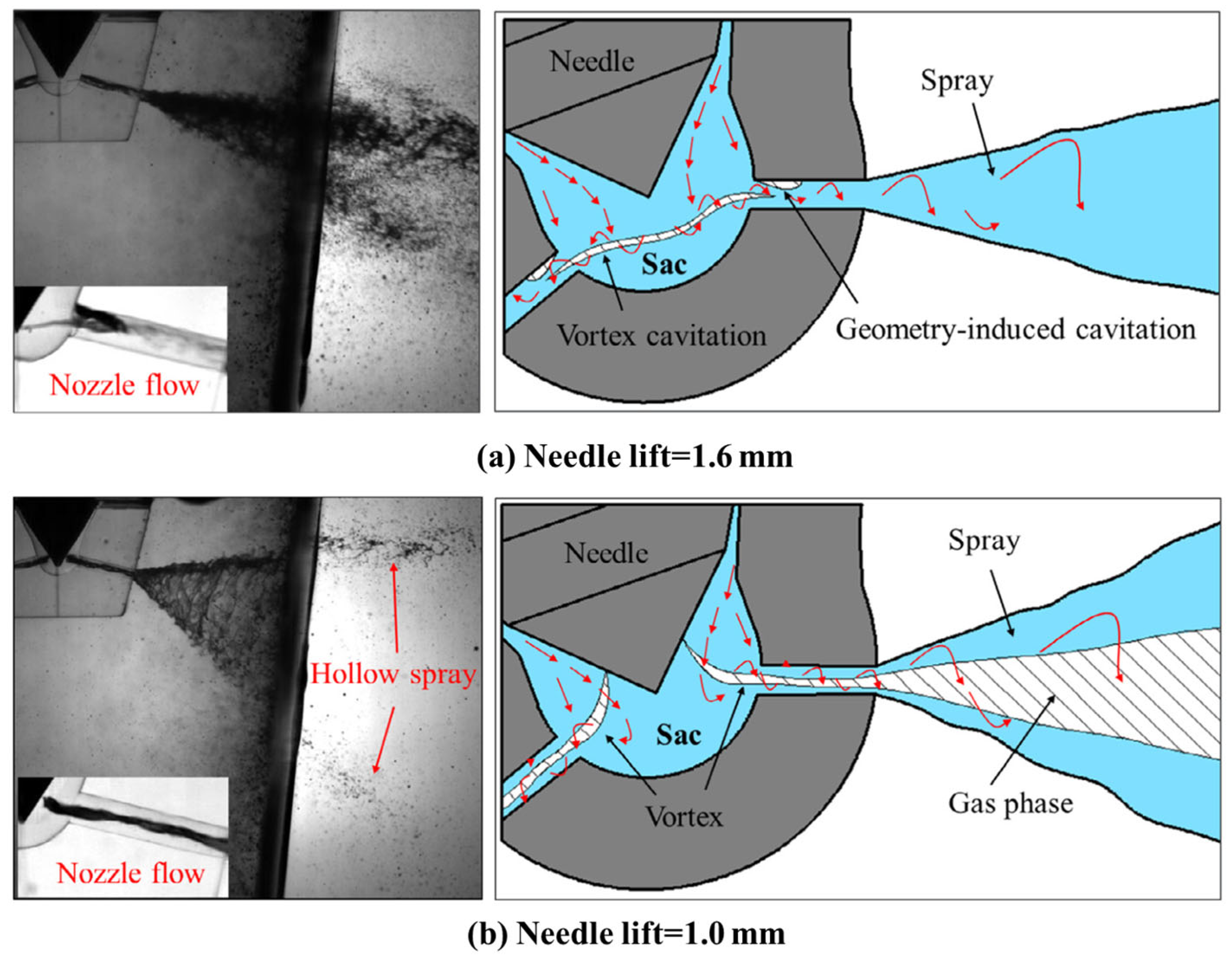
Shi et al. [53] investigated the effects of injection pressure, needle lift, and orifice geometry on cavitation using a scaled-up transparent nozzle platform. The results indicated that under their experimental conditions, increasing the injection pressure and needle lift promoted the formation of sheet cavitation, whereas a convergent orifice suppressed its development. In addition, string cavitation was correlated with vortex intensity and variations in the spray cone angle. Cao et al. [54] employed a scaled-up optical nozzle, as shown in Figure 6, to compare the quasi-steady vortex cavitation and spray characteristics at model-scale needle lifts of 1.0 mm and 1.6 mm, as well as to analyze the evolution mechanisms of sheet, cloud, and string cavitation. Because these lift values are scaled-up model parameters, they should not be directly equated to the needle lifts of real-size injectors without explicit geometric scaling relationships.
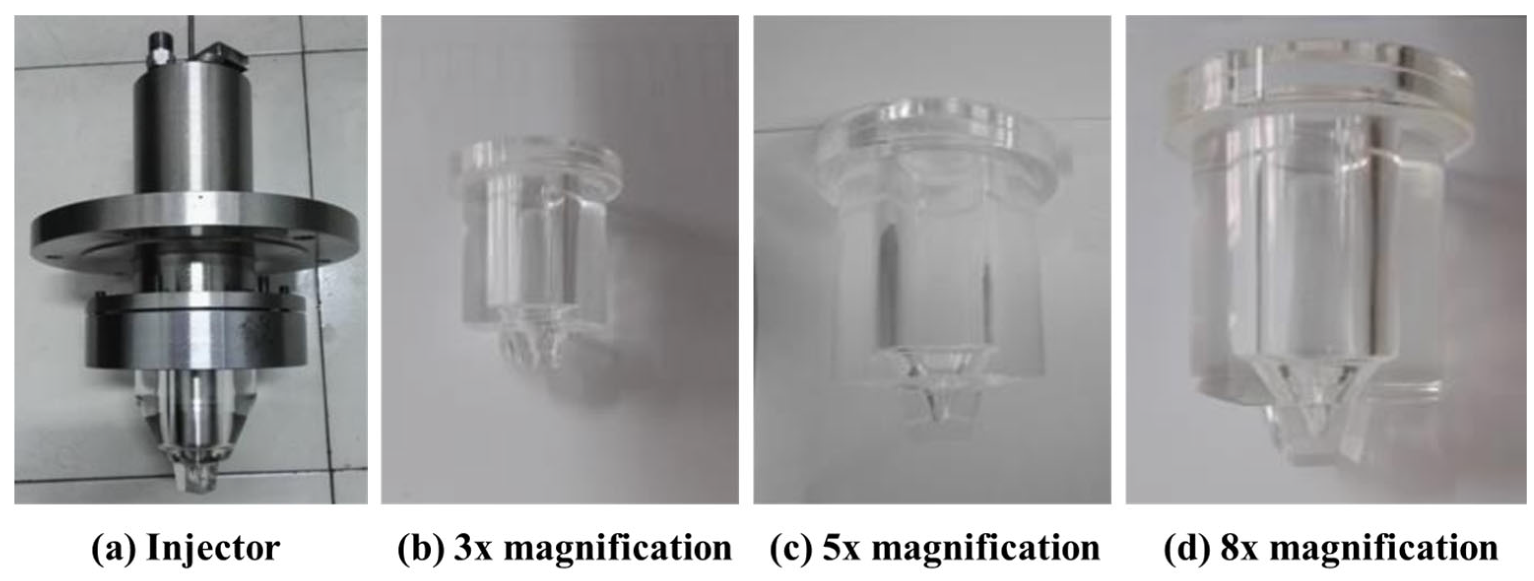
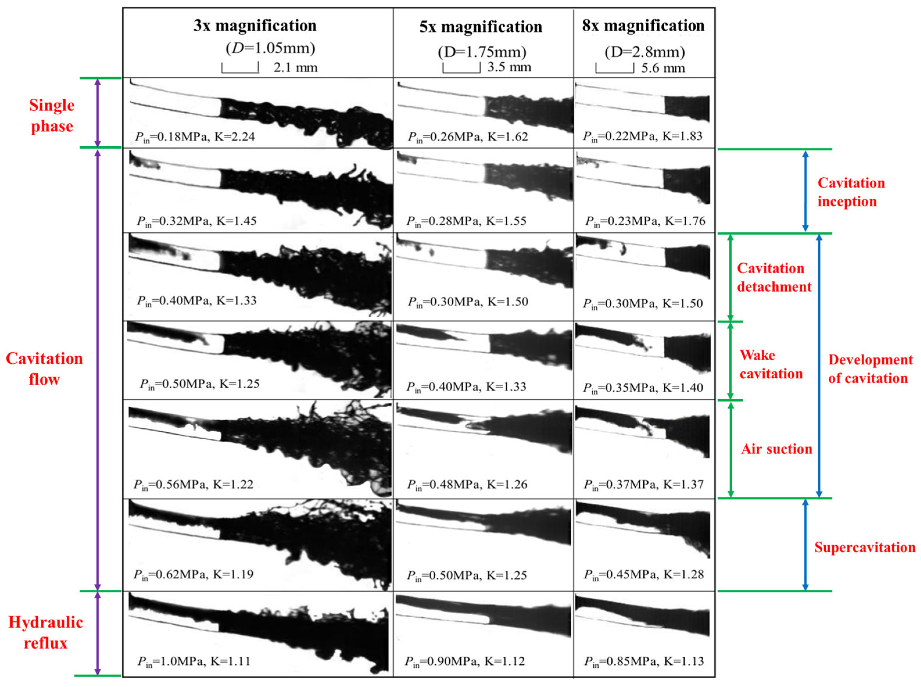
Zhang et al. [55] conducted visualization experiments using a transparent nozzle enlarged by a factor of 10. Their results showed that increasing the fuel temperature reduced the cavitation inception pressure and enlarged the cavitation region. Although a convergent orifice could suppress geometrically induced cavitation, string cavitation became more pronounced at elevated temperatures. As shown in Figure 7, Guo [56] employed geometrically similar transparent nozzles scaled by factors of 3, 5, and 8 relative to a prototype orifice diameter of 0.35 mm to investigate the effects of injection pressure and orifice scale on cavitating flow and spray morphology. With increasing injection pressure, the internal flow successively underwent cavitation inception, cavitation development, super cavitation, and hydraulic flip. During the super cavitation stage, the cavitation region extended to the orifice outlet, accompanied by an increase in the spray cone angle and intensified near-field jet breakup. Further comparison showed that, as presented in Figure 8, the critical cavitation inception numbers of the three nozzles were 1.45, 1.50, and 1.76, respectively, indicating that orifice scale affects both the conditions for cavitation inception and the transitions between different flow regimes. It should be noted that results obtained using enlarged transparent nozzles are primarily useful for elucidating cavitation morphology and flow evolution, and scale-similarity effects must be considered when extrapolating these findings to full-scale metallic nozzles. If the Reynolds number, Weber number, cavitation number, and transient timescale cannot be simultaneously matched, flow separation, cavitation inception, bubble-shedding frequency, and spray breakup inside the orifice may differ from those occurring in an actual nozzle. Therefore, visualization results from scaled-up transparent nozzles should be interpreted according to their specific purpose. They are generally reliable for qualitative identification of cavitation mechanisms and flow evolution, and can provide trend-level comparisons under similar conditions. However, due to unresolved scale effects and incomplete similarity between model and real injectors, their quantitative transferability to full-scale high-pressure injectors remains a methodological challenge.
Overall, optical visualization experiments serve as a crucial approach for investigating internal cavitating flows within injector nozzles and validating CFD models, enabling the observation of cavitation inception sites, gas-phase distributions, cavity shedding, and flow regime transitions. However, current visualization experiments still present certain limitations. First, due to the limited strength of transparent nozzle materials, the applied test pressures often fail to fully replicate the realistic operating conditions of high-pressure or ultra-high-pressure common rail injectors. Second, scale effects may arise between scaled-up transparent nozzles and real-size nozzles, as their orifice dimensions, wall roughness, and flow Reynolds numbers do not perfectly match those of actual nozzles. Third, light refraction through transparent materials, optical occlusion, and the two-dimensional projection of three-dimensional cavitating structures can cause optical distortions, compromising the accurate identification of cavitation regions and flow details. Furthermore, the high temperatures, high pressures, transient back pressures, and complex injection boundary conditions present in actual engines are difficult to fully replicate in laboratory visualization rigs. Therefore, future studies should integrate optical visualization data with mass flow rates, injection rates, pressure signals, and CFD results, striving to conduct multi-parameter validations under actual-size and high-pressure transient conditions. Furthermore, visualization experiments inherently entail uncertainties in both the experimental procedures and image processing. Test results can be affected by pressure and temperature fluctuations, shot-to-shot repeatability, nozzle manufacturing tolerances, and instrument calibration; meanwhile, the accurate identification of cavitation boundaries and gas-phase regions can be compromised by image resolution, exposure and illumination conditions, refractive distortions, image noise, and threshold selection. Consequently, future studies should conduct repeated trials and report measurement uncertainties, while adopting standardized image processing and quantitative evaluation methods to enhance the reliability and comparability of experimental findings.

3.5. Research on Flow Field Characteristics of Injector Nozzles Under Different Fuels

In terms of the flow field characteristics of injector nozzles with different fuels, Cao et al. [57] investigated the physicochemical properties, mutual solubility stability, and spray characteristics of ethanol/biodiesel/diesel blends at various blending ratios using high-speed photography. The results indicated that adding ethanol improves the atomization performance of the blend, whereas adding biodiesel enhances the mutual solubility stability of the ethanol/diesel blends. Yu et al. [58] compared the spray characteristics of diesel, gasoline, kerosene and their blends and found that diesel has the longest spray penetration while gasoline is the most cavitated within the nozzle, producing the maximum spray cone angle. He et al. [59] analyzed the effect of five different proportions of gasoline–diesel blends (D100G0, D80G20, D60G40, D40G60, D20G80) on cavitation flow and spray characteristics through visualization tests. The results showed that even small amounts of gasoline significantly increase the injection rate and spray fluctuations, especially during needle opening and closing of a conical orifice nozzle. The percentage of gasoline has a relatively limited effect on cavitation intensity and duration, but promotes increased cone angle and spray fluctuation. The aforementioned studies by Yu et al. and He et al. emphasize different aspects regarding the effects of gasoline. Yu et al. compared the overall cavitation tendencies across different fuels, whereas He et al. focused on the sensitivity of cavitation intensity and duration to variations in the gasoline–diesel blend ratio. Differences in the investigated nozzles, fuel temperatures, orifice geometries, needle lifts, and analyzed transient phases likely account for the divergent conclusions between the two studies.
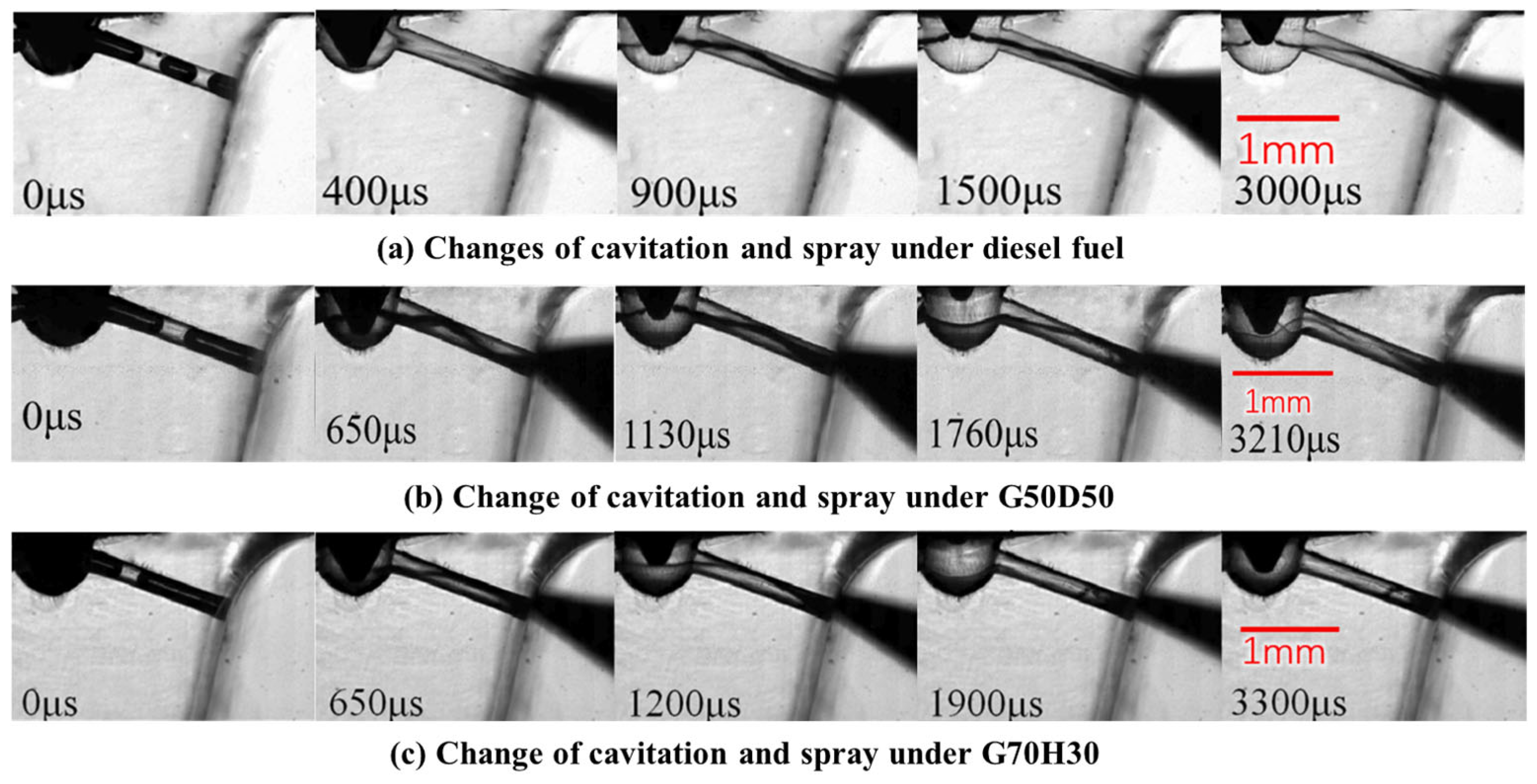
Wang et al. [60] investigated the cavitation and spray characteristics within the nozzle of a high-pressure common rail injector when blending gasoline, diesel fuel, and hydrogenated catalyzed biodiesel (HCB) as fuel. Experimental analysis of intra-nozzle cavitation and spray was visualized using an actual-size optical nozzle as shown in Figure 9. The results show that mixing gasoline with diesel fuel increases the nozzle column cavitation and spray cone angle, especially at low needle lift. In addition, elevating the fuel temperature can significantly affect cavitation, but has less effect on swirl.
It should be noted that inconsistencies exist across studies regarding the reporting of fuel viscosity, density, surface tension, saturated vapor pressure, compressibility, and distillation characteristics, which hinders direct comparisons of the results. Fuel properties, in conjunction with nozzle hole geometry, fuel temperature, and injection conditions, collectively influence the pressure distribution within the nozzle hole, cavitation phenomena, and spray characteristics; therefore, further research focused on the synergistic matching of these multiple factors remains essential.

3.6. Research on Flow Field Characteristics of Fuel Injectors Optimized by Artificial Intelligence

With the development of the high-pressure common rail fuel injection system towards high pressure, multiple injection and precise control, the nonlinear relationship among the flow field, injection quantity, injection rate and spray characteristics in the nozzle becomes more complex. Although traditional CFD simulation and visualization experiments can reveal flow mechanisms such as cavitation, turbulence, and eddies inside the nozzle, there are still certain limitations in terms of computational cost, experimental period, and rapid prediction. Therefore, in recent years, machine learning, deep learning, and data-driven modeling methods have gradually been applied to analyze the flow field characteristics and optimize injection parameters of high-pressure common rail fuel injector nozzles [16,61]. Lu et al. [62] further combined deep learning and transfer learning to propose a prediction model architecture for main injection and pre-injection rates under multiple injection strategies. The upper limit of the 95% confidence interval for injection quantity prediction error is less than 4.98%, which improves the adaptability of the model under different operating conditions. Choi et al. [63] used artificial neural networks to predict the fuel injection rate changes of piezoelectric injectors, providing a new method for the rapid prediction of the fuel injection process. Xu et al. [64] combined optical experiments, numerical simulation, and machine learning to conduct sensitivity analysis on nozzle flow coefficient, spray morphology and cavitation erosion risk, and used RBF neural network and NSGA-II algorithm to carry out multi-objective optimization of nine-hole nozzle parameters. In terms of the prediction of nozzle spray and flow field characteristics, Yun et al. [65] predicted and analyzed the injection characteristics of high-pressure injectors by combining injection rate test and machine learning methods, and R2 exceeded 0.99; Vaz et al. [66] used a deep neural network to predict the spray penetration and spray cone angle of the marine injector, and the accuracy rate of the unseen data was 95%. The analysis of feature importance showed that the injection pressure, nozzle number, outlet nozzle diameter and capsule hole volume were the main parameters affecting spray behavior.
The research framework for the flow field of fuel injectors based on AI is shown in Figure 10. This method can establish the nonlinear mapping between the nozzle structure, injection parameters, and fuel physical properties and the injection quantity, injection rate, cavitation and spray characteristics, providing support for rapid flow field prediction, structure optimization and injection strategy regulation. Compared with traditional optimization methods, AI optimization methods have advantages in the fast prediction and modeling of complex nonlinear relationships. Traditional nozzle optimization mainly relies on CFD parametric analysis, experimental design, response surface method, etc. By repeatedly changing the nozzle structure and operating parameters, and comparing the flow coefficient, cavitation intensity, spray characteristics, and other indicators, the flow mechanism can be better revealed, but the calculation and test costs are high. AI method can establish the mapping relationship between structural parameters, operating parameters, flow field characteristics, and spray performance based on test, CFD, and bench data, thus assisting in the rapid prediction and multi-objective optimization of fuel injection volume, injection rate, cavitation risk and spray characteristics.
It should be noted that a higher R2 value or prediction accuracy alone is not sufficient to prove the reliability of the model. Model evaluation should also consider sample size and sources, dataset partitioning, error metrics, and data leakage risks. However, a detailed comparison of dataset size, partition strategies, validation methods, and extrapolation capability among existing AI-based injector studies remains difficult, because this information is not consistently reported and the datasets are usually obtained from different sources, including CFD simulations, visualization experiments, injection tests, and engine bench measurements. If the training data only covers a limited number of structures and operating conditions, its generalization ability in the absence of injection pressure, back pressure, fuel type, and nozzle structure still needs to be independently verified. The computational costs of different algorithms also vary. Shallow models train faster, while ensemble learning and deep neural networks can describe complex nonlinear relationships, but they have higher time costs and higher requirements for data, computing power, and multi parameter optimization. At present, the relevant data mainly come from visual tests, fuel injection rate tests, spray diagnoses, CFD simulations and engine bench tests. However, the high-pressure transient test cost is high, the published standardized data are limited, and the data conditions and formats of different studies are quite different. Therefore, subsequent research should integrate experimental data, CFD results, and physical constraints to enhance the stability, interpretability, and cross condition generalization ability of the model.

3.7. Limitations and Summary of Flow Field Research on Injector Nozzles

3.7.1. Limitations of Studying the Flow Field of Injector Nozzles

The internal flow of high-pressure common rail injector nozzles has characteristics such as a high pressure difference and strong transient, multiphase and multi-scale coupling. In the modeling of transient multiphase flow, existing numerical models are still difficult to fully describe the needle valve motion, fuel phase transition, bubble evolution and pressure wave propagation. Although the fixed needle valve or quasi steady state assumption can reduce computational costs, it is difficult to reflect the flow fluctuations, local backflow, and cavitation transient changes during the opening and seating stages of the needle valve [67]. The dynamic grid and immersion boundary methods can describe the needle valve motion, but they require high grid, time step, and computational resources.
In terms of turbulence cavitation interaction, commonly used cavitation models are based on the assumption of homogeneous mixing and empirical mass transfer relationships, simplifying the distribution of gas nuclei, dissolved gas precipitation, non-equilibrium phase transition, and bubble collapse, which may affect the prediction of cavitation initiation position, vapor volume fraction, pressure peak, fuel injection rate, and outlet velocity. There is a bidirectional coupling effect between turbulence and cavitation, and the RANS model has high computational efficiency, but its analytical ability for cloud cavitation shedding, linear cavitation, and transient vortex structures is limited; LES and hybrid RANS-LES methods can obtain richer transient information, but the computational cost is higher.
The two-dimensional CFD method is suitable for preliminary analysis of axisymmetric or simplified nozzles, but it is difficult to reflect asymmetric flow, needle valve eccentricity, inter nozzle interference, and three-dimensional eddies. The three-dimensional model can more fully describe the actual structure and transient flow field, but its accuracy is still affected by boundary conditions, mesh quality, time step, turbulence model, cavitation model, and experimental verification level. In addition, the inlet fillet, surface roughness, needle valve eccentricity, and machining errors of actual spray holes are often difficult to fully reflect in idealized models. Transparent magnifying nozzles may have scale effects, and the actual size of optical nozzles is limited by materials, pressure, and observation conditions [68]. The existing research still has problems such as insufficient multi-parameter coupling analysis, limited validation of complex nozzle engineering, and unclear matching rules between fuel and nozzle structures. Although AI models can be used for predicting fuel injection quantity, injection rate, and flow field, they are still limited by data quality, model generalization, and other factors.
It should be emphasized that these methodological limitations are closely related to the specific studies discussed in previous sections. For example, CFD-based investigations of nozzle structure and operating parameters may be affected by the selection of turbulence and cavitation models, boundary conditions, and transient needle-motion treatment, which influence the prediction of cavitation evolution and flow characteristics. Similarly, visualization studies provide valuable evidence for identifying cavitation morphology and flow evolution, but their conclusions should be interpreted considering scale effects and experimental constraints. Therefore, the applicability of reported conclusions should always be evaluated together with the corresponding model assumptions and experimental conditions.

3.7.2. Summary of Research on Flow Field of Injector Nozzles

In summary, the current research on the flow field of high-pressure common rail injector nozzles mainly involves structural and operating parameters, non-circular injection holes, visualization experiments, different fuels, and AI intelligent optimization. It focuses on the influence of nozzle geometry and operating conditions on internal flow, the flow control effect of complex nozzles, the transient evolution of cavitation, fuel property effects, and flow field prediction and injection optimization [69]. To compare the objects, methods, main conclusions, and existing shortcomings of various research directions, this article has summarized and summarized them, as shown in Table 1.
Table 1 presents a qualitative summary based on research topics and technical methodologies, primarily serving to compare the main focuses, common methods, and existing limitations across different research directions, rather than ranking performance based on unified quantitative criteria. Due to significant differences in nozzle structure, working conditions, fuel properties, as well as numerical and experimental methods among different studies, this article does not provide a unified parameter ranking for individual studies, but focuses on the common patterns, applicable conditions, and existing limitations in different research directions. In general, the research on high-pressure common rail injectors has formed a research system combining numerical simulation, visual testing, spray diagnosis, and engine bench testing. The study of structure and working parameters provides a foundation for nozzle optimization design. Noncircular and composite nozzle holes expand the ideas of atomization and mixing enhancement. Visualization experiments provide support for flow mechanism analysis and numerical model verification. Research on different fuels helps evaluate the fuel adaptability of fuel injection systems. AI methods expand the technical path of flow field prediction and injection control.

4. Research Trends and Unresolved Problems Regarding Injector Nozzles Flow Field Characteristics

The flow field characteristics of high-pressure common rail injector nozzles directly impact fuel atomization, fuel–air mixing, and combustion processes, which in turn affect engine power output, fuel economy, and pollutant emissions. Driven by continually increasing injection pressures, enhanced injection control precision, the application of alternative fuels, and advancements in artificial intelligence, research on the flow fields of these nozzles must not only track technological trends but also delve deeper into the unresolved scientific issues concerning internal flow mechanisms, structural optimization, experimental validation, and intelligent control [66,70,71,72,73,74,75]:
(1)
Under ultra-high injection conditions, the coupling mechanisms among cavitation, turbulence, and spray breakup remain to be further clarified. Driven by increasingly stringent requirements for energy conservation and emission reduction in diesel engines, high-pressure common rail injector nozzles must accommodate higher injection pressures to enhance fuel atomization quality. However, elevated injection pressures alter the pressure gradients, fuel flow velocities, turbulence intensities, and cavitation extent within the orifice. While moderate cavitation promotes fuel breakup, excessive cavitation can cause flow losses, pressure fluctuations, and cavitation erosion on the orifice walls. Therefore, future studies should further elucidate the interactions among cavitation formation, cavity collapse, turbulence evolution, and spray breakup under ultra-high pressures, clarifying how different cavitation stages affect spray quality and nozzle lifespan.
(2)
Under multiple injections and transient needle motion, the dynamic evolution of the internal flow field within the injector nozzle remains unclear. Advancements in electronic control and sensor technologies enable high-pressure common rail systems to achieve more precise control over injection timing, fuel quantity, and the number of injections. However, during multiple injection events—such as pilot, main, and post-injections—the rapid opening and seating of the needle induce pressure fluctuations, local backflow, and transient cavitation variations. Therefore, future research must further investigate the relationships among needle lift, injection intervals, injection pressure fluctuations, and the transient internal flow field within the orifice, thereby providing a foundation for the real-time optimization and control of fuel injectors.
(3)
The synergistic optimization mechanisms between complex orifice geometries and next-generation fuel injectors still require in-depth investigation. Parameters such as orifice diameter, length-to-diameter ratio, inlet corner radius, taper angle, needle lift, and non-circular orifice geometries all influence the pressure distribution, velocity field, turbulence, and cavitation behavior within the nozzle. Future geometric optimization of injector nozzles must not only enhance flow capacity and atomization quality but also account for cavitation erosion, manufacturing feasibility, and long-term reliability. For elliptical, intersecting, multi-tier, and tapered orifices, as well as novel multi-intersecting nozzles, the internal vortex structures, cavitation distribution, and exit velocity non-uniformity remain to be further clarified. As next-generation injectors evolve toward higher pressures, faster responses, and multiple injections, the synergistic optimization among nozzle geometry, needle motion, and injection control strategies will become a crucial research direction.
(4)
The matching relationship between alternative fuels and injector nozzle flow fields remains to be further elucidated. Driven by the development of low-carbon and clean fuels, the application of biodiesel, ethanol–diesel blends, gasoline–diesel blends, and other alternative fuels in diesel engines has garnered increasing attention. Differences in fuel properties—such as viscosity, density, surface tension, saturation vapor pressure, and volatility—alter the conditions for cavitation inception within the orifice, spray cone angle, penetration length, and fuel–air mixing processes. Therefore, future studies must further clarify how various fuel properties affect the internal flow field and spray characteristics of the nozzle. Furthermore, matching optimization that integrates these properties with orifice geometry, injection pressure, and back pressure should be conducted to enhance combustion efficiency and reduce pollutant emissions.
(5)
The reliability and uncertainty of CFD predictions still need further evaluation. Traditional CFD can reveal the internal pressure, velocity, turbulence, and cavitation characteristics of injector nozzles, but the prediction results are easily affected by grid scale, time step, boundary conditions, fuel properties, and turbulence and cavitation model selection. There may be differences in the prediction of cavitation initiation, vapor volume fraction, outlet velocity, and turbulence kinetic energy among different models. Therefore, it is necessary to strengthen the sensitivity analysis of grid and time step, model comparison, and uncertainty quantification, and to combine multiple indicators such as actual size high-pressure visualization, mass flow rate, fuel injection rate, and pressure signal verification to improve the credibility of the model and the comparability of research results.
(6)
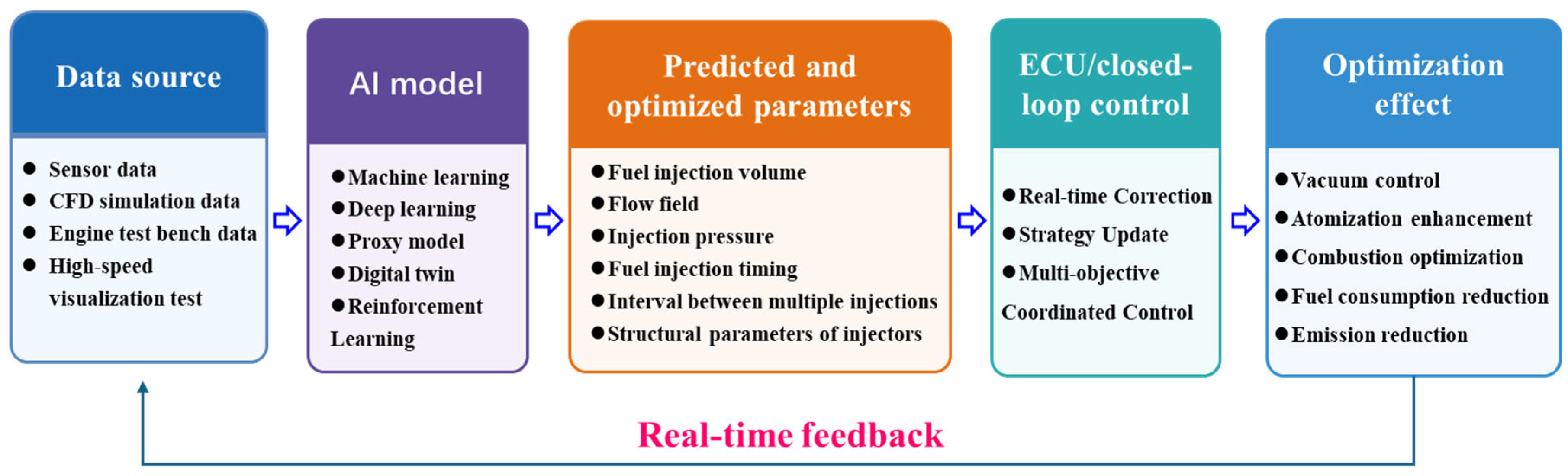
AI, digital twins, and real-time injector optimization still require deep integration with physical mechanisms. Current research is evolving from conventional mechanism-based analysis and single-parameter optimization toward an integrated framework of “data acquisition–model prediction–intelligent optimization–closed-loop control.” Based on sensor measurements, visualization experiments, CFD simulations, and engine bench data, machine learning, deep learning, surrogate models, and digital twins can be used to predict and optimize injection quantity, injection rate, injection pressure, injection timing, injection interval, and nozzle orifice geometry. Combined with ECU-based control, these approaches can further enable operating-state identification and real-time adjustment of injection strategies, as illustrated in Figure 11. However, existing models remain limited by data quality, cross-condition generalization capability, and physical interpretability. Therefore, closer integration of data-driven methods with flow physics, experimental validation, and real-time control is still needed.
In summary, future research on the flow field characteristics of high-pressure common rail injector nozzles will evolve toward the synergistic development of higher injection pressures, greater precision, decarbonization, and intelligent control. However, its core mission extends beyond merely increasing injection pressure or optimizing nozzle geometries; it involves resolving critical issues such as the coupling mechanisms of ultra-high-pressure transient multiphase flows, optimization mechanisms for complex orifice geometries, alternative fuel matching, CFD uncertainty quantification, and real-time control utilizing AI and digital twins. Future efforts can further integrate CFD simulations, visualization experiments, engine bench data, and artificial intelligence algorithms to drive nozzle flow field research from traditional mechanistic analysis toward rapid prediction, synergistic optimization, and intelligent control.

5. Conclusions

This paper reviews research on the flow field characteristics of high-pressure common rail injector nozzles. Existing studies demonstrate that injection pressure, back pressure, inlet rounding, needle lift, and fuel properties are key factors governing the internal flow field and spray characteristics. Specifically, injection and back pressures generally influence cavitation development, exit velocity, and spray breakup, although the magnitude and specific effects depend on nozzle geometry, operating conditions, and cavitation regimes. Inlet rounding and orifice shape primarily affect the discharge coefficient and cavitation intensity by altering inlet flow separation and local pressure losses. Furthermore, needle lift can significantly affect transient flows, vortex structures, and injection rate fluctuations during the opening and closing phases of the injection event. While moderate cavitation enhances fuel breakup and atomization, excessive or unstable cavitation can reduce the effective flow area, induce flow losses and pressure fluctuations, and cause cavitation erosion on the orifice walls. Consequently, nozzle optimization should not focus solely on isolated flow or atomization metrics; instead, it requires a comprehensive evaluation of flow capacity, atomization quality, cavitation erosion risk, and structural reliability.
Currently, research on the internal flow fields of high-pressure common rail injector nozzles continues to exhibit context-dependent conclusions with considerable variability among different studies. Findings related to non-circular orifice configurations, optimal nozzle geometries, cavitation intensity, and atomization enhancement should be interpreted with consideration of the effects of orifice geometry, operating conditions, fuel properties, experimental scales, and numerical modeling approaches. Therefore, they should not be directly generalized as universal principles. For instance, the effects of elliptical orifices on cavitation and the discharge coefficient are not entirely consistent across different aspect ratios, inflow directions, and boundary conditions. The impact of elevated injection pressure on spray performance is also stage-dependent, potentially exhibiting distinct trends across the regimes of cavitation inception, cavitation development, super cavitation, and hydraulic flip. Furthermore, conclusions regarding cavitation intensity and spray fluctuations in studies involving gasoline/diesel blends should be interpreted considering the effects of fuel temperature, orifice geometry, and transient needle motion. In addition, computational fluid dynamics-based predictions are influenced by mesh resolution, time-step selection, boundary conditions, fuel properties, and the choice of turbulence and cavitation models. Scale effects may also introduce uncertainties when transferring observations obtained from scaled-up transparent nozzles to real-size injector configurations. Therefore, future studies should avoid identifying an optimal nozzle design based solely on a single geometry, numerical framework, or operating condition, and should instead consider multi-parameter interactions and cross-condition validation.
Future research should further strengthen the cross-validation among numerical simulations, visualization experiments, injection rate testing, pressure measurements, and engine bench tests. For numerical simulations, grid and time-step independence analyses, alongside comparisons of turbulence and cavitation models, should be conducted. Furthermore, multi-metric validation should be performed by integrating mass flow rates, injection rates, pressure signals, visualized cavitation morphologies, and spray characteristics. In terms of visualization experiments, particular attention should be paid to pressure limitations, scale effects, optical distortion, and image processing uncertainties, utilizing validation data obtained under actual-size, high-pressure transient conditions whenever possible. Regarding artificial intelligence optimization, the sample size, train-test partitioning, and error metrics must be explicitly specified to avoid evaluating model reliability based solely on high R2 values or prediction accuracies. Building upon this foundation, machine learning, surrogate models, digital twins, and electronic control unit closed-loop control can be further integrated to conduct the co-optimization of nozzle geometries, injection strategies, and alternative fuel adaptation. This will propel research on the flow fields of high-pressure common rail nozzles toward higher pressures, enhanced precision, decarbonization, and intelligentization.

Author Contributions

Conceptualization, M.H., Y.Q. and P.H.; methodology, W.Y., P.H. and X.D.; investigation, M.H. and Y.Q.; resources, M.H., W.Y. and S.Z.; writing—original draft preparation, M.H. and W.Y.; writing—review and editing, W.Y.; visualization, Y.Q. and M.Y.; supervision, M.H., P.H., X.D. and M.Y.; project administration, W.Y., Y.Q. and M.Y. All authors have read and agreed to the published version of the manuscript.

Funding

This research received no external funding.

Data Availability Statement

No new data were created or analyzed in this study. Data sharing is not applicable to this article.

Acknowledgments

The authors would like to thank Wentao Yuan for his support and guidance. I would like to express my gratitude to my colleagues for their care and assistance in my daily work.

Conflicts of Interest

Author Mingtao Yuan was employed by the company Hudong Zhonghua Shipbuilding (Group) Co., Ltd. The remaining authors declare that the research was conducted in the absence of any commercial or financial relationships that could be construed as a potential conflict of interest. The Hudong Zhonghua Shipbuilding (Group) Co., Ltd. had no role in the design of the study; in the collection, analyses, or interpretation of data; in the writing of the manuscript, or in the decision to publish the results.

References

  1. Lu, X.; Zhao, J.; Grekhov, L. Research on the influential factors related to the fuel leakage rate in the plunger-sleeve clearance of high pressure common rail system. Int. J. Engine Res. 2024, 25, 662–676. [Google Scholar] [CrossRef] [Scilit]
  2. Li, J.H.; Wei, S.; Chen, H.L. Research on the Closed-Loop Control of Common Rail Pressure by Simulated Calculation for High Pressure Common Rail Diesel. Mach. Des. Manuf. 2022, 7, 59–64. [Google Scholar]
  3. Li, R.C.; Yuan, W.T.; Xu, J.K.; Wang, L.; Chi, F.; Wang, Y.; Liu, S.Q.; Lin, J.; Zhang, Q.G.; Chen, L.Z. Study of the optimization of rail pressure characteristics in the high-pressure common rail injection system for diesel engines based on the response surface methodology. Processes 2023, 11, 2626. [Google Scholar] [CrossRef] [Scilit]
  4. Tahar, S.; Saidoune, F.Z.; Didi, F.; Zirari, M.; Ykrelef, H.; Elsayed, E.E. Effect of Dual-Hole Nozzle Injection Angle on Primary Breakup and Near-Nozzle Spray Dynamics of High-Pressure Diesel Jets: Volume-of-Fluid Numerical Investigation. Processes 2026, 14, 2405. [Google Scholar] [CrossRef] [Scilit]
  5. Singh, V.; Gupta, S.K. Performance enhancement of diesel engine using Karanja oil methyl ester as a fuel blend with diesel by variable injector nozzle hole. Eng. Res. Express 2024, 6, 025514. [Google Scholar] [CrossRef] [Scilit]
  6. Zhao, J.; Grekhov, L.; Ma, X.; Wang, Q. Review of internal flow and spray characteristics of diesel injectors. Energy Fuels 2021, 35, 84–118. [Google Scholar]
  7. Wang, Y.; Li, S.; Liu, H.; Wang, H. Coupled simulation of internal flow and primary breakup of diesel spray using a VOF-LES framework. Int. J. Multiph. Flow 2022, 148, 103936. [Google Scholar]
  8. Salvador, F.J.; De la Morena, J.; Martinez-Lopez, J.; Rubio-Cash, C. Assessment of the boundary conditions and turbulence model effects on the internal flow in a diesel injector. Energy Convers. Manag. 2018, 164, 182–196. [Google Scholar]
  9. He, L.G.; Gong, W.R.; Zhao, J.H. Research on fuel injection quantity fluctuation characteristics and optimization improvement of dual-fuel engines. Energy 2025, 324, 135953. [Google Scholar] [CrossRef] [Scilit]
  10. Mao, B.; Chen, Z.; Reitz, R.D. Uncertainty quantification in internal combustion engine simulations: A review. Int. J. Engine Res. 2021, 22, 2118–2139. [Google Scholar]
  11. Zhou, M.; Wang, Y.; Li, X. Applications of machine learning in spray, combustion, and emissions of internal combustion engines: A review. Energy 2023, 268, 126685. [Google Scholar]
  12. Aravind, S.; Barik, D.; Paramasivam, P.; Balasubramanian, D.; Kale, U.; Kilikevicius, A. AI based optimization of injection pressure for hydrogen and spirogyra biodiesel dual fuel engine to enhance combustion performance and emission characteristics. Sci. Rep. 2026, 16, 8017. [Google Scholar] [CrossRef] [Scilit] [PubMed]
  13. Öztürk, G.; Fırat, M.; Aslan, A.; Okcu, M. Experimental investigation and artificial intelligence-based prediction of combustion and emission characteristics of DBM15 diesel fuel at variable injection timings in a compression ignition engine. Appl. Therm. Eng. 2026, 290, 129913. [Google Scholar] [CrossRef] [Scilit]
  14. Markov, V.; Sa, B.; Kamaltdinov, V.; Neverov, V.; Zherdev, A. Investigation on the effect of the flow passage geometry of diesel injector nozzle on injection process parameters and engine performances. Energy Sci. Eng. 2022, 10, 552–577. [Google Scholar] [CrossRef] [Scilit]
  15. Abramek, K.F.; Osipowicz, T.; Mozga, Ł. The use of neural network algorithms for modeling injection doses of modern fuel injectors. Combust. Engines 2021, 185, 10–14. [Google Scholar] [CrossRef] [Scilit]
  16. Lu, X.; Zhao, J.; Markov, V.; Wu, T. Study on precise fuel injection under multiple injections of high pressure common rail system based on deep learning. Energy 2024, 307, 132784. [Google Scholar] [CrossRef] [Scilit]
  17. Inam, S.A.; Khan, A.A.; Ahmed, N.; Mazhar, T.; Shahzad, T.; Khan, S.; Saeed, M.M.; Hamam, H. A novel deep learning approach for investigating liquid fuel injection in combustion system. Discov. Artif. Intell. 2025, 5, 32. [Google Scholar] [CrossRef] [Scilit]
  18. Gao, Z.G. Research on Injection Stability and Pressure Fluctuation of High Pressure Common Rail System. Ph. D Thesis, Beijing Jiaotong University, Beijing, China, 2022. [Google Scholar]
  19. Chen, J.; Liu, L.; Zhao, B. Injection Mechanism in Asymmetric Fuel Injector in Diesel Engine Based on Multiphase Flow-Cavitation Coupling Model. Flow Meas. Instrum. 2026, 109, 103248. [Google Scholar] [CrossRef] [Scilit]
  20. Li, C.; He, Z.X.; Guan, W.; Guo, G.M. Investigation of the effects of vortex-induced string cavitation on flow and spray characteristics within diesel fuel injection nozzles. At. Sprays 2024, 34, 37–56. [Google Scholar] [CrossRef] [Scilit]
  21. Azizi, S.; Shervani-Tabar, M.T. Experimental and image processing study on the effect of the cavitation phenomenon in a nozzle injector on the hydrodynamic behavior of the spray. AUT J. Mech. Eng. 2024, 8, 67–82. [Google Scholar]
  22. Zhang, Y.F.; Zhang, G.X.; Wu, D.W.; Wang, Q.; Nadimi, E.; Shi, P.H.; Xu, H.M. Parameter sensitivity analysis for diesel spray penetration prediction based on GA-BP neural network. Energy AI 2024, 18, 100443. [Google Scholar] [CrossRef] [Scilit]
  23. Millo, F.; Jafari, M.J.; Piano, A.; Postrioti, L.; Brizi, G.; Vassallo, A.; Pesce, F.; Fittavolini, C. A fundamental study of injection and combustion characteristics of neat Hydrotreated Vegetable Oil (HVO) as a fuel for light-duty diesel engines. Fuel 2025, 379, 132951. [Google Scholar] [CrossRef] [Scilit]
  24. Xu, J.; Fan, L.Y.; Li, B.; Wei, Y.P.; Lan, Q.; Wang, G.Z. Research on pressure wave decoupling method for the nozzle of common rail electronically controlled injector based on water hammer theory. Int. J. Engine Res. 2024, 25, 882–895. [Google Scholar] [CrossRef] [Scilit]
  25. Cao, T.Y.; Jin, J.J.; Qu, Y.P. Cavitation phenomenon and spray atomization in different types of diesel engine nozzles: A systematic review. SAE Int. J. Engine 2024, 17, 743–766. [Google Scholar] [CrossRef] [Scilit]
  26. Chen, P.; Xu, R.W.; Liu, Z.M.; Liu, J.B.; Zhang, X.S. Homogeneous field measurement and simulation study of injector nozzle internal flow and near-field spray. Processes 2023, 11, 2533. [Google Scholar] [CrossRef] [Scilit]
  27. Osipowicz, T.; Abramek, K.F.; Mozga, Ł. Comparing polynomials and neural network to modelling injection dosages in modern CI engines. Appl. Sci. 2022, 12, 2246. [Google Scholar] [CrossRef] [Scilit]
  28. He, J.J.; An, Q.S.; Jin, J.S.; Feng, S.; Zhang, K.M. Experimental study and simulation of cavitation shedding in diesel engine nozzle using proper orthogonal decomposition and large eddy simulation. J. Therm. Sci. 2023, 32, 1487–1500. [Google Scholar] [CrossRef] [Scilit]
  29. Atac, O.F.; Moon, S.; Huang, W.D.; Ozawa, D.S. Hole number effect on internal and discharged flow characteristics of diesel injector during transient operation. Flow Meas. Instrum. 2022, 88, 102252. [Google Scholar] [CrossRef] [Scilit]
  30. Klyus, O.; Szczepanek, M.; Kidacki, G.; Krause, P.; Olszowski, S.; Chybowski, L. The effect of internal combustion engine nozzle needle profile on fuel atomization quality. Energies 2024, 17, 266. [Google Scholar] [CrossRef] [Scilit]
  31. Villagomez-Moreno, J.; Dominguez-Gonzalez, A.; Manriquez-Padilla, C.G.; Saucedo-Dorantes, J.J.; Perez-Cruz, A. Enhancing Injector Performance Through CFD Optimization: Focus on Cavitation Reduction. Computers 2025, 14, 215. [Google Scholar] [CrossRef] [Scilit]
  32. Shen, D.P.; Sou, A.; Wada, Y.; Ueki, Y. Single string cavitation and swirling flow in a nozzle and a hollow-cone spray. J. Fluid Sci. Technol. 2025, 20, JFST0014. [Google Scholar] [CrossRef] [Scilit]
  33. Singh, K.; Dwivedi, G.; Verma, T.N.; Shukla, A.K. Energy, exergy, emissions and sustainability assessment of hydrogen supplemented diesel dual fuel turbocharged common rail direct injection diesel engine. Int. J. Hydrogen Energy 2025, 104, 378–392. [Google Scholar] [CrossRef] [Scilit]
  34. Bambhania, M.P.; Patel, N.K. Hydrodynamic cavitation in the fuel injector nozzle and its effect on spray characteristics: A Review. J. Heat Mass Transf. Res. 2023, 10, 1–20. [Google Scholar]
  35. Özgünoğlu, M.; Mouokue, G.; Oevermann, M.; Bensow, R.E. Numerical investigation of cavitation erosion in high-pressure fuel injector in the presence of surface deviations. Fuel 2025, 386, 134174. [Google Scholar] [CrossRef] [Scilit]
  36. Cao, T.Y. The Study on Cavitating Pattern Characteristics and Their Effects on Pressure Fluctuations and Spray in the Diesel Nozzle. Ph. D Thesis, Jiangsu University, Wuxi, China, 2022. [Google Scholar]
  37. Sun, Z.Y.; Li, G.X.; Chen, C.; Yu, Y.S.; Gao, G.X. Numerical investigation on effects of nozzle’s geometric parameters on the flow and the cavitation characteristics within injector’s nozzle for a high-pressure common-rail DI diesel engine. Energy Convers. Manag. 2015, 89, 843–861. [Google Scholar] [CrossRef] [Scilit]
  38. Wang, P.L.; Dong, Z.G.; Ya, G.; Duan, Z.B. Effect of Nozzle Structural Parameters on Flow Field of Methanol Fuel injection. Mech. Sci. Technol. Aerosp. Eng. 2018, 37, 998–1004. [Google Scholar]
  39. Guo, Q.; Cao, J.; Yi, Z.; Zhi, Z.F.; Ma, S. Risk Analysis of Cavitation Erosion for Diesel Engine Injector Nozzle Holes. Veh. Engine 2024, 01, 21–27. [Google Scholar]
  40. Zhang, J.H.; Li, C.Y.; Pei, G.B.; Li, Z.H.; Wang, X.B.; Lin, J.W. Research and Optimization on Flow and Spray Characteristics of Nozzles. Chin. Intern. Combust. Engine Eng. 2022, 43, 41–48. [Google Scholar]
  41. Örley, F.; Hickel, S.; Schmidt, S.J.; Adams, N.A. Large-Eddy Simulation of turbulent, cavitating fuel flow inside a 9-hole Diesel injector including needle movement. Int. J. Engine Res. 2016, 18, 195–211. [Google Scholar] [CrossRef] [Scilit]
  42. Li, C.Y. Research and Structure Optimization on Internal Flow and Atomization Performance of Diesel Injection Nozzle. Master’s Thesis, Tianjin University, Tianjin, China, 2022. [Google Scholar]
  43. Zhang, Z.H.; Yang, Q.; Sun, B.G.; Wu, D.W.; Xu, D. Experimental Study on Pressure Fluctuation Characteristics and Fuel Property Parameters of 250 MPa Common Rail System. Trans. Beijing Inst. Technol. 2019, 39, 1113–1117. [Google Scholar]
  44. Wang, C.Q. The Impact of the Transient Needle Moving on the Flow and Spray Characteristics of the Diesel Injector. Ph. D Thesis, Jiangsu University, Wuxi, China, 2020. [Google Scholar]
  45. Yin, B.; Xu, B.; Jia, H.; Yu, S. The effect of elliptical diesel nozzles on spray liquid-phase penetration under evaporative conditions. Energies 2020, 13, 2234. [Google Scholar] [CrossRef] [Scilit]
  46. Zhang, L. Research on Cavitation Erosion of High-Pressure Common Rail Fuel Nozzle and Corresponding Jet Atomization Characteristics. Ph. D Thesis, Jiangsu University, Wuxi, China, 2020. [Google Scholar]
  47. Molina, S.; Salvador, F.J.; Carreres, M.; Jaramllo, D. A computational investigation on the influence of the use of elliptical orifices on the inner nozzle flow and cavitation development in diesel injector nozzles. Energy Convers. Manag. 2014, 79, 114–127. [Google Scholar] [CrossRef] [Scilit]
  48. Sa, B.; Klyus, O.; Markov, V.; Kamaltdinov, V. A numerical study of the effect of spiral counter grooves on a needle on flow turbulence in a diesel injector. Fuel 2021, 290, 120013. [Google Scholar] [CrossRef] [Scilit]
  49. Leng, X.Y.; Jin, Y.; He, Z.X. Numerical Simulation on Internal Flow Characteristics of Intersecting Hole Nozzles. Trans. CSICE 2015, 33, 522–529. [Google Scholar]
  50. Zhang, L.; He, Z.X.; Guan, W.; Wang, Q.; Som, S.D. Simulations on the cavitating flow and corresponding risk of erosion in diesel injector nozzles with double array holes. Int. J. Heat Mass Transf. 2018, 124, 900–911. [Google Scholar] [CrossRef] [Scilit]
  51. He, Z.X.; Zhong, W.J.; Wang, Q.; Jiang, Z.C.; Shao, Z. Effect of nozzle geometrical and dynamic factors on cavitating and turbulent flow in a diesel multi-hole injector nozzle. Int. J. Therm. Sci. 2013, 70, 132–143. [Google Scholar] [CrossRef] [Scilit]
  52. Watanabe, H.; Nishikori, M.; Hayashi, T.; Suzuki, M.; Kakehashi, N.; Ikimoto, M. Visualization analysis of relationship between vortex flow and cavitation behavior in diesel nozzle. Int. J. Engine Res. 2015, 16, 5–12. [Google Scholar] [CrossRef] [Scilit]
  53. Shi, D.X.; Zhou, Z.; Guo, L.X.; Yang, H.T.; Xia, X.L. Visualization of Cavitating Flow in Diesel Injector Nozzles and its Effects on Spray. Trans. CSICE 2019, 37, 54–59. [Google Scholar]
  54. Cao, T.; He, Z.; Zhou, H.; Guan, W.; Zhang, L.; Wang, Q. Experimental study on the effect of vortex cavitation in scaled-up diesel injector nozzles and spray characteristics. Exp. Therm. Fluid Sci. 2020, 113, 110016. [Google Scholar] [CrossRef] [Scilit]
  55. Zhang, X.; He, Z.; Wang, Q.; Tao, X.; Zhou, Z.; Xia, X.; Zhang, W. Effect of fuel temperature on cavitation flow inside vertical multi-hole nozzles and spray characteristics with different nozzle geometries. Exp. Therm. Fluid Sci. 2018, 91, 374–387. [Google Scholar] [CrossRef] [Scilit]
  56. Guo, G.M. Transient Characteristics of Special Flow Phenomena in Diesel Injector Nozzles and Their Effects on Spray. Ph. D Thesis, Jiangsu University, Wuxi, China, 2019. [Google Scholar]
  57. Cao, J.M.; Wu, K.; Peng, C. Experimental Research on Ethanol/ Biodiesel/ Diesel Blend Fuel. Intern. Combust. Engines 2020, 3, 12–16. [Google Scholar]
  58. Yu, W.; Yang, W.; Zhao, F. Investigation of internal nozzle flow, spray and combustion characteristics fueled with diesel, gasoline and wide distillation fuel (WDF) based on a piezoelectric injector and a direct injection compression ignition engine. Appl. Therm. Eng. 2017, 114, 905–920. [Google Scholar] [CrossRef] [Scilit]
  59. He, Z.X.; Hu, B.H.; Wang, J.Q.; Guo, G.M.; Feng, Z.H.; Wang, C.Q.; Duan, L. The cavitation flow and spray characteristics of gasoline-diesel blends in the nozzle of a high-pressure common-rail injector. Fuel 2023, 350, 128786. [Google Scholar] [CrossRef] [Scilit]
  60. Wang, J.Q.; He, Z.X.; Duan, L.; Zhou, H.; Zhong, W.J.; Guo, G. Effect of diesel/gasoline/HCB blends and temperature on string cavitating flow in common-rail injector nozzle. Fuel 2021, 304, 121402. [Google Scholar] [CrossRef] [Scilit]
  61. Liu, B.X.; Fei, H.Z.; Wang, L.P.; Fan, L.Y.; Yang, X.T. Real-time estimation of fuel injection rate and injection volume in high-pressure common rail systems. Energy 2024, 298, 131386. [Google Scholar] [CrossRef] [Scilit]
  62. Lu, X.; Zhao, J.; Markov, V.; Grekhov, L. Deep transfer learning-based model for real-time prediction of multiple injection rate in common rail system for marine engine. Energy 2025, 332, 137206. [Google Scholar] [CrossRef] [Scilit]
  63. Choi, E.; Park, J.; Hwang, J.; Oh, H.; Manin, J.; Sim, H.S. Injection rate measurements and Machine-Learning based predictions of ECN Spray A-3 piezoelectric injector. Appl. Therm. Eng. 2024, 254, 123827. [Google Scholar] [CrossRef] [Scilit]
  64. Xu, S.H.; Guo, G.M.; Bai, T.Y.; Yang, K.; Guan, W.; Yuan, J.P.; He, Z.X. Structural sensitivity analysis and multi-objective optimization of liquid nozzle performances with the internal cavitation flow. Int. J. Engine Res. 2025, 27, 146808. [Google Scholar] [CrossRef] [Scilit]
  65. Yun, L.; Park, J.; Sim, H.S. Combined Experimental and Machine Learning Study of Injection Characteristics of High-Pressure Spray Injector. J. Propuls. Energy 2025, 5, 39–51. [Google Scholar] [CrossRef] [Scilit]
  66. Vaz, M.G.J.; Karathanassis, I.; Gavaises, M.; Mouokue, G. Data-driven prediction of spray macroscopic characteristics for marine injectors using neural networks. Fuel 2026, 405, 136736. [Google Scholar] [CrossRef] [Scilit]
  67. Yang, C.J.; Zhao, B. Study on the influence mechanism of geometric parameters of asymmetric fuel injectors on internal transient flow and cavitation characteristics. J. Eng. Appl. Sci. 2026, 73, 198. [Google Scholar] [CrossRef] [Scilit]
  68. Gao, Y.; Li, P.; Huang, W.D. Investigations of internal flow characteristics of multi-hole nozzle using X-ray imaging technique. Processes 2025, 13, 309. [Google Scholar] [CrossRef] [Scilit]
  69. Ferrari, A.; Vassallo, A. The impact of the common rail fuel injection system on performance and emissions of modern and future compression ignition engines. Energies 2025, 18, 5259. [Google Scholar] [CrossRef] [Scilit]
  70. Wei, Y.P.; Fan, L.Y.; Zhang, H.W.; Gu, Y.Q.; Deng, Y.C.; Leng, X.Y.; Fei, H.Z.; He, Z.X. Experimental investigations into the effects of string cavitation on diesel nozzle internal flow and near field spray dynamics under different injection control strategies. Fuel 2022, 309, 122021. [Google Scholar] [CrossRef] [Scilit]
  71. Chen, C.; Wang, Y.; Tian, Y.; Deng, W. Effects of pulse injection on the flow field structure and combustion performance in a kerosene-fueled supersonic combustor. Acta Astronaut. 2025, 226, 479–493. [Google Scholar] [CrossRef] [Scilit]
  72. Sun, Y.; Vegad, C.S.; Li, Y.; Renou, B.; Nishad, K.; Demoulin, F.X.; Wang, W.; Hasse, C.; Sadiki, A. Evaluation of turbulent co-flow effects on liquid fuel atomization including spray evolution from a pressure swirl atomizer. Int. J. Multiph. Flow 2025, 184, 105100. [Google Scholar] [CrossRef] [Scilit]
  73. Zhang, Q.; Li, X.; Li, Z.; Xu, Y.; Yu, Y.; Li, Z.; Yao, B. Numerical simulation of combustion and emission characteristics in a H2-Diesel dual-fuel DICI engine with a coaxial dual-layer nozzle. Int. J. Hydrogen Energy 2025, 145, 970–990. [Google Scholar] [CrossRef] [Scilit]
  74. Xi, X.; Liu, C.X.; Pan, Y.J.; Zhang, R.Q.; Song, S.S.; Xu, S.L.; Liu, H. Numerical investigation of in-nozzle cavitation and flow characteristics in diesel engines using a multi-fluid quasi-VOF model coupled with a cavitation model. Int. J. Heat Fluid Flow 2025, 115, 109858. [Google Scholar] [CrossRef] [Scilit]
  75. Wu, H.; Zhang, X.; Zhao, P.; Fang, Y.; Yang, X.; Zheng, H. Multi-Objective Cooperative Optimization of Key Structural Parameters of Pressure Swirl Nozzles Under Microgravity. Appl. Sci. 2026, 16, 1883. [Google Scholar] [CrossRef] [Scilit]
Figure 1. Conceptual framework linking nozzle structure, internal flow field, spray characteristics, and combustion emissions.
Processes 14 02757 g001
Figure 2. Fuel distribution inside the injection nozzle during the needle valve closing stage.
Processes 14 02757 g002
Figure 3. Numerical simulation results of transient cavitation evolution during the lifting and seating of the injector.
Processes 14 02757 g003
Figure 4. Comparison of cavitation between circular holes and different elliptical holes.
Processes 14 02757 g004
Figure 5. Comparison of double-layer nozzle cavitation.
Processes 14 02757 g005
Figure 6. Hollow spray caused by hole-to-hole vortex cavitation and needle-originated vortex cavitation.
Processes 14 02757 g006
Figure 7. Different proportions of enlarged injector nozzles.
Processes 14 02757 g007
Figure 8. Comparison of cavitation flow patterns inside nozzles with different scaling ratios.
Processes 14 02757 g008
Figure 9. Cavitation and spray characteristics under diesel and diesel–gasoline blended fuels.
Processes 14 02757 g009
Figure 10. Research and optimization framework for flow field characteristics of AI-driven injector nozzles.
Processes 14 02757 g010
Figure 11. AI-based framework for high-pressure common rail fuel injection control and nozzle flow field optimization.
Processes 14 02757 g011
Table 1. Comparison of main research directions on flow field characteristics of high-pressure common rail injector nozzles.
Research DirectionMain Research ObjectCommon MethodsFocus IndicatorsMain ConclusionsExisting Shortcomings
Structure and working parametersSpray hole diameter, aspect ratio, inlet fillet, taper angle, needle valve lift, injection pressure, back pressure, etc.CFD simulation, VOF model LES, experimental verification.Mass flow rate, cavitation volume fraction, outlet velocity, turbulence energy.The nozzle structure and pressure conditions will significantly affect the cavitation development, nozzle flow field characteristics and spray fragmentation effect.Model dependency; mostly focused on single parameter analysis, insufficient research on multi parameter coupling.
Non-circular spray hole structureElliptical hole, cross hole, multi-layer hole, conical hole, spiral groove structure.Numerical simulation, structural optimization, local mesh refinement.Cavitation position, vortex intensity, spray cone angle, penetration.Non-circular spray holes can improve fuel–air mixing and enhance atomization, but may also pose a risk of localized cavitation.Model dependencies and geometric characteristics; the difficulty of processing complex structures is high, and there is insufficient engineering application verification.
Visualization experimentTransparent magnifying nozzle, actual size optical nozzle, observation of cavitation morphology.High speed photography, optical diagnosis, transparent nozzle testing.Bubble cavitation, sheet cavitation, cloud cavitation, line cavitation, super cavitation.It can intuitively reveal the evolution process of cavitation inside the nozzle, which is an important means to verify the accuracy of CFD models.Most experiments are limited by pressure, scale, and materials, making it difficult to fully reproduce the real working conditions.
The impact of different fuelsDiesel, biodiesel, ethanol/diesel, gasoline/diesel, hydrogen/diesel, etc.Spray test, visualization test, engine bench test.Spray cone angle, penetration distance, cavitation intensity, combustion efficiency.Fuel viscosity, density, and evaporation can alter cavitation and atomization processesInsufficient research on the coupling of multi fuel and nozzle structures.
AI intelligent optimizationFuel injection quantity prediction, injection rate estimation, injection strategy optimization, and rapid flow field prediction.Machine learning, deep learning, reinforcement learning, digital twins, surrogate models, etc.response characteristics, emission performance (NOx and soot), fuel consumption, and control stability.AI can be used for fuel injection quantity prediction, injection strategy optimization, and real-time closed-loop control, which is an important direction for the future.Model accuracy dependence; data quality, model generalization ability, physical interpretability, and real-time deployment in vehicles still need to be addressed.
Disclaimer/Publisher’s Note: The statements, opinions and data contained in all publications are solely those of the individual author(s) and contributor(s) and not of MDPI and/or the editor(s). MDPI and/or the editor(s) disclaim responsibility for any injury to people or property resulting from any ideas, methods, instructions or products referred to in the content.