Article

Research on Virtual Synchronous Machine Control of Air Conditioner Loads Participating in Power Frequency Regulation


1
State Key Laboratory of Technology and Equipment for Defense Against Power System Operational Risks, Nanjing 211106, China
2
Nari Technology Co., Ltd., Nanjing 211106, China
3
Nanjing Center for Applied Mathematics, Nanjing 211135, China
*
Author to whom correspondence should be addressed.
Processes 2026, 14(17), 2726; https://doi.org/10.3390/pr14172726
Submission received: 30 June 2026 / Revised: 14 August 2026 / Accepted: 18 August 2026 / Published: 26 August 2026

Abstract

High penetration of renewable energy reduces power-system inertia and increases the need for fast-frequency-support resources. This study proposes an integrated virtual synchronous machine (VSM) control framework for clusters of variable-frequency air conditioners (VFACs). The proposed method incorporates synchronous-machine-like inertia and damping into compressor-side power control, aggregates heterogeneous VFACs using fuzzy C-means clustering, and adaptively adjusts virtual inertia according to grid-frequency variations. Virtual-storage flexibility is further incorporated into coordinated frequency regulation. Simulations on the IEEE two-machine, five-node system verify the effectiveness of the proposed framework. Under a representative 3 MW load-increase disturbance, the frequency deviation from the nominal value is reduced from 0.11 Hz to 0.04 Hz. The results indicate that large-scale VFAC clusters can provide fast and coordinated demand-side frequency support while improving system frequency stability.

1. Introduction

As renewable energy sources (e.g., wind and solar) are increasingly integrated into the power grid, system inertia decreases, raising concerns about frequency stability. Traditional frequency regulation relies on synchronous generators for inertial response and control. High renewable penetration can therefore exacerbate frequency deviations and slow frequency recovery, creating a growing need for fast-frequency-regulation resources. Recent advances in high-efficiency perovskite and 2D material photovoltaics [1,2] further reinforce this need as converter-interfaced renewable generation expands.
Demand response (DR) has become an important complement to grid regulation. Among DR resources, variable-frequency air-conditioning loads are particularly promising because of their large population, wide distribution, and continuous power-modulation capability [3,4]. Unlike fixed-speed air conditioners, VFACs continuously regulate compressor speed, enabling flexible grid support while maintaining indoor comfort. Related studies have addressed direct and optimized load control, uncertainty-aware demand response, and data-driven load forecasting [5,6,7,8,9,10]. Recent TCL studies also use virtual-battery or virtual-energy-storage models to characterize comfort-constrained power, energy, and SOC-like flexibility for scheduling and grid services [11,12,13].
Virtual synchronous machine (VSM) technology emulates the inertia and damping characteristics of synchronous machines, providing inertia-like support for low-inertia systems. Recent studies have examined virtual-synchronous control, inertia estimation, measurement and impedance effects, oscillation damping, and renewable-energy applications [14,15,16,17,18,19,20,21]. Although VSM control has been widely studied on the generation side, its application to large-scale VFAC clusters remains comparatively limited, particularly with respect to aggregation, adaptive inertia, and coordinated primary/secondary frequency regulation.
Load-side VSM studies have shown that converter-interfaced loads, such as electric-vehicle chargers, can emulate inertia and damping and provide grid-frequency support [20,22]. However, TCL/virtual-battery studies primarily characterize thermal flexibility, whereas load-side VSM studies mainly address device-level dynamics. Neither line of research simultaneously addresses heterogeneous VFAC aggregation, adaptive virtual inertia, and thermal-flexibility-constrained primary/secondary frequency regulation. The comparison among these representative approaches is summarized in Table 1.
Table 1. Comparison with representative demand-side frequency-support approaches.
ApproachThermal FlexibilityVSM CharacteristicsAggregation and Frequency Services
Conventional TCL/DR [3,4,5,6,7,8]Partly consideredNo explicit inertia/dampingAggregate demand response
Virtual-battery TCL [11,12,13]Explicit power/energy/SOC-like limitsNo VSM dynamicsLarge-scale scheduling and grid services
Load-side VSM [20,22]Generally not explicitInertia/damping; mainly device-levelFast local frequency support
Proposed methodVirtual-storage flexibilityVSM with adaptive virtual inertiaFCM aggregation; primary + secondary regulation
The specific research gap is therefore the lack of a device-to-cluster framework that connects load-side VSM dynamics with the thermal constraints and heterogeneity of large-scale VFAC populations. Compared with existing approaches, this study makes three contributions: (1) it develops a compressor-side VSM model for continuous inertia- and damping-like VFAC power response; (2) it aggregates heterogeneous compressors using fuzzy C-means clustering and adapts virtual inertia according to frequency deviation and variation; and (3) it coordinates autonomous primary response with aggregator-assisted secondary regulation using adjustable capacity and virtual-storage SOC.

2. Principle and Control Methods of Variable-Frequency Air Conditioning

2.1. Operation of Variable-Frequency Air Conditioning

Variable-frequency air conditioners (VFACs) incorporate a frequency-control module for the compressor motor, allowing continuous adjustment of compressor speed. This provides smoother temperature regulation, improved user comfort, and lower energy consumption by reducing frequent compressor start-stop cycling. As a result, VFACs now account for a substantial share of the air-conditioning market and are increasingly used in residential and commercial applications.

2.2. Start-Stop Control and Temperature Regulation of Variable-Frequency Air Conditioning

Based on the VFAC model, this study considers two representative demand-response modes for grid support: start-stop control and temperature-setpoint regulation.

2.2.1. Start-Stop Control [5]

Start-stop control is the most direct load-regulation method. Upon receiving a dispatch command, the controlled air conditioner is switched from the on state to the off state, producing an immediate reduction in electrical demand.

2.2.2. Temperature Regulation Control [7]

Compared with start-stop control, temperature-setpoint regulation uses the thermal inertia of the conditioned space to adjust the load more gradually. Raising the set temperature reduces compressor speed and electrical demand while limiting the impact on user comfort. It generally produces a smaller rebound than direct interruption and is therefore widely used by load aggregators.

2.2.3. Cluster Control

In practical applications, cluster control is used to obtain a sufficiently large aggregate load response. During a control interval, the air-conditioning cluster reduces or suspends part of its power consumption. As indoor temperatures rise, many units subsequently require additional power to restore the temperature setpoint, which can create a synchronized rebound above the pre-control load. To mitigate this effect, a rotating-control strategy divides the cluster into subgroups and regulates them sequentially, spreading the recovery process and reducing the rebound peak.

3. Virtual Synchronous Machine Modeling of Variable-Frequency Air Conditioning Load

3.1. Retrofit of Virtual Synchronous Machine for Variable-Frequency Air Conditioning Load

Implementing VSM control in VFACs requires several hardware and communication modifications, including a grid-voltage measurement module, a fully controlled bridge rectifier, and WiFi or ZigBee communication modules. After modification, the air conditioner estimates grid frequency from the measured voltage signal. When the frequency deviation exceeds a prescribed threshold, VSM control adjusts compressor speed and power, thereby modulating the electrical load. The unit can also receive control commands from the load aggregator and return operating-status information, forming a closed-loop interface between the aggregator and the grid dispatch center.

3.2. Compressor-Side VSM Modeling and Control

VSM control is applied to the load power control to establish a load-side VSM model for the VFAC [23].
Assuming a pole-pair number of 1 for the VSM and combining synchronous-machine rotor dynamics with power-frequency droop control, the active-power frequency-control equations are given by Equations (1)–(3):
J d Δ ω d t = P ref P load ω + K f ( f s f ref ) D Δ ω ,
Δ ω = ω ω ref ,
ω = d θ d t ,
In the equation, P ref represents the reference active power of the load’s virtual synchronous machine, and P load denotes the actual active power absorbed by the load’s virtual synchronous machine. f s is the actual system frequency; f ref is the reference system frequency; and K f is the frequency droop coefficient. J and D are the rotational inertia and damping coefficient of the virtual synchronous machine, respectively. ω is the angular frequency of the virtual synchronous machine; ω ref is the rated angular frequency; Δ ω is the angular frequency deviation; and θ is the electrical angle of the virtual synchronous machine.
Physically, Equation (1) represents the virtual swing dynamics of the load-side VSM. The virtual inertia J determines how strongly the load resists rapid frequency changes, while the damping coefficient D suppresses oscillations during the transient response. Therefore, J mainly affects the rate and depth of the frequency excursion, whereas D mainly influences the oscillation and settling behavior.
The VSM emulates the excitation regulator of a synchronous machine for reactive-power/voltage control. Combining the electromagnetic transient relationships, the reactive-power/voltage control equations are given by Equations (4)–(6):
E = ω M f i f = ω M f K R d E 0 E + Δ E Q + Δ E U d t ,
Δ E Q = K q ( Q ref Q load ) ,
Δ E U = K u ( U ref U s ) .
In the equation, E represents the output voltage of the reactive power-voltage control, and E0 is the no-load potential of the virtual synchronous machine. Mf denotes the virtual mutual inductance between the stator and rotor, and if is the virtual excitation current. ΔEQ is the reactive power voltage adjustment, and ΔEU is the voltage adjustment. KR is the excitation regulation coefficient; Kq is the reactive power regulation coefficient; and Ku is the voltage regulation coefficient. Qref and Qload represent the reference and actual reactive power load of the virtual synchronous machine, while Uref and Us are the system’s voltage reference and actual RMS voltage, respectively.
Thus, the virtual voltage vector of the VSM is given by Equation (7):
e abc = E sin θ E sin ( θ 2 π / 3 ) E sin ( θ + 2 π / 3 ) ,
The virtual voltage vector is transformed using the Park transformation, and a voltage-current dual-loop controller is then applied to the rectifier. The corresponding control equations are given by Equations (8) and (9):
e d * = K p i d * i d + K i i d * i d ω L s i q + u d ,
e q * = K p i q * i q + K i i q * i q ω L s i d + u q ,
In Equations (8) and (9), e d * and e q * represent the d-axis and q-axis components of the reference voltage at the input ports of the air conditioning compressor rectifier in the dq coordinate system, respectively. Kp and Ki are the proportional and integral coefficients of the PI control loop in the current inner-loop control, respectively. i d * and i q * denote the d-axis and q-axis components of the reference current on the AC side of the rectifier in the dq coordinate system. id and iq also represent the AC side current components in the dq coordinate system. Ls is the line inductance on the AC side of the rectifier. ud and uq represent the d-axis and q-axis components of the rectifier’s AC bus-side voltage in the dq coordinate system [24].
The resulting dq-axis voltage commands are transformed back to the abc frame and used to drive the compressor rectifier through SVPWM. This completes the load-side VSM implementation for the compressor-motor rectifier.

4. Control Strategy of VFAC VSM Clusters for Grid Frequency Regulation

4.1. Aggregation Method for VFAC VSM Clusters

4.1.1. Selection of Compressor Motor Characteristic Vectors

The third-order electromechanical transient model is commonly used for induction motors in power-system studies [25,26]. Compressor motors with similar electrical and mechanical parameters can therefore be represented by an equivalent motor. In this study, the stator impedance Xs, rotor impedance X'r, mutual inductance Lm, rotational inertia Ja, and initial slip s0 are used as the five-dimensional characteristic vector for clustering [27]. Motors assigned to the same cluster are assumed to have coherent speed dynamics.

4.1.2. Fuzzy C-Means Clustering

Fuzzy C-means (FCM) clustering groups compressor motors with similar characteristic vectors before equivalent-model aggregation.
The n motors are partitioned into c clusters. Initial cluster centers are generated, and the squared distance between each motor characteristic vector and each cluster center is used to update the membership matrix. The objective function is given by Equation (10):
min   O j = min k = 1 n i = 1 c ( u i k ) j ( d i k ) 2   = k = 1 n min i = 1 c ( u i k ) j ( d i k ) 2 ,
For reproducibility, the five-dimensional feature vectors are min-max normalized before the distance calculation. In Equation (10), j > 1 is the fuzzification exponent and is set to j = 2. The membership values and cluster centers are updated iteratively until the change in the objective function falls below 10−5 or 100 iterations are completed. The cluster number c is selected by balancing aggregation resolution against equivalent-model complexity. The dominant computational cost comes from repeated distance calculations and membership updates for all motors and cluster centers. Because clustering is performed offline before real-time VSM control, it does not add to the online control burden.

4.1.3. Equivalent-Motor Grouping and Aggregation

After FCM clustering, the transient models within each cluster are aggregated to obtain one equivalent compressor-motor model per cluster. The equivalent-model equations are given by Equations (11)–(16).
T eq d E q , eq d t = E q , eq + X eq X eq X eq V + T eq ( ω ω s ) E d , eq ,
T eq d E d , eq d t = E d , eq T eq ( ω ω s ) E q , eq ,
M eq X eq d ω d t = V E d , eq ( a eq X eq ω 2 + b eq X eq ω + c eq X eq ) ,
T = T 0 X X ,
T 0 = X r + X m ω s R r ,
T m = a ( 1 s ) 2 + b ( 1 s ) + c ,
In the equation, the subscript “eq” denotes the equivalent parameters of the equivalent motor; T 0 represents the transient open-circuit time constant; ω0 and ωs are the system’s reference and nominal angular frequencies, respectively; X = Xs + Xm represents the rotor’s open-circuit reactance; X = Xs + XrXm/(Xr + Xm) represents the rotor’s short-circuit reactance under locked-rotor conditions; M is the inertia time constant; V is the bus voltage; Tm is the motor torque, and a, b, and c are mechanical torque coefficients. The characteristic parameters of the aggregated equivalent motors in each cluster group are thus obtained.
The aggregated equivalent compressor motors are controlled using the load-side VSM strategy, with appropriate control parameters selected to form the VFAC VSM cluster model.

4.2. VFAC VSM Clusters in Grid Interaction

The VFAC VSM cluster can participate in fast grid-frequency regulation, with aggregators organizing available load resources into clusters and dispatching them according to grid commands. The interaction framework comprises the grid-dispatch layer, node-control layer, and load-response layer. Under dispatch instructions, the VSM cluster can provide primary and secondary frequency regulation, peak shaving, and emergency power support. After regulation, the aggregator restores the loads gradually to mitigate rebound.
Practical deployment requires bidirectional communication (e.g., WiFi/ZigBee) between VFACs and the aggregator for secondary-regulation commands and status feedback, whereas the primary VSM response is triggered by locally measured frequency and therefore does not require round-trip communication. The simulations assume ideal measurement and communication. In practice, frequency-estimation and filtering delays, controller and communication latency, packet loss, and communication outages may degrade coordination. Authenticated and encrypted command channels, device authentication, and fail-safe local control are required to mitigate false-command and data-manipulation risks. Quantitative evaluation of these nonidealities is reserved for future hardware-in-the-loop tests.

4.3. Control Strategy for VFAC VSM Clusters in Fast Grid-Frequency Regulation

4.3.1. Power-Frequency Characteristics of VFAC VSM Clusters

(1)
Primary Frequency Regulation
The VFAC VSM cluster autonomously responds to grid-frequency deviations through active-power-frequency control. Its active-power-frequency characteristic is analogous to that of an active load. When the grid frequency falls below the lower limit of the primary-regulation deadband, VSM control reduces compressor power to support the generation-load balance. Conversely, when the frequency rises above the upper limit, compressor power increases, thereby moderating the frequency rise.
(2)
Secondary Frequency Regulation
The VFAC VSM cluster provides primary frequency regulation through frequency-dependent control and can also respond to secondary-regulation commands. The dispatch center determines the required regulation capacity from the frequency deviation and allocates it among the air-conditioning load aggregators. The aggregators then distribute the assigned capacity to the VSM clusters, adjusting the virtual inertia J and damping coefficient D to achieve the required secondary-regulation response.

4.3.2. Adaptive Frequency-Regulation Strategy for VFAC VSM Clusters

By integrating the variable-frequency air conditioning load VSM control model and its power-frequency characteristics [28], the closed-loop transfer function for the active power of the VSM is obtained as follows:
G i ( s ) = P i ( s ) P ref i ( s ) = 1 J ω 0 E 0 U s Z s 2 + ( D J + K ω J ω 0 ) s + 1 J ω 0 E 0 U s Z ,
In Equation (17), Pi and Prefi represent the active power and reference active power of the i-th virtual synchronous machine, E0 and Us denote the no-load voltage and the actual grid voltage, respectively, Z is the input impedance of the load virtual synchronous machine, Kω is the frequency regulation coefficient, and J and D are the rotational inertia and damping coefficients.
The undamped natural angular frequency ωn and damping ratio ξ of the load-side VSM are obtained from Equation (17):
ω n = 1 J ω 0 E 0 U s Z ξ = D 2 1 J ω 0 E 0 U s Z + K ω 2 1 J ω 0 E 0 U s Z ,
Equation (18) shows that J and D jointly determine the transient characteristics of the VSM. Increasing J slows the frequency response and mitigates rapid frequency excursions, whereas increasing D improves damping and suppresses power and frequency oscillations. This trade-off motivates the adaptive adjustment of J adopted in the following control strategy.
With a small virtual inertia, the grid frequency changes rapidly after a disturbance and also recovers quickly after the disturbance is cleared. With a large inertia, both the initial deviation and the recovery evolve more slowly. Thus, a fixed small J may provide insufficient inertial buffering, whereas an excessively large J can delay recovery. The adaptive strategy therefore reduces J as the frequency approaches recovery, combining stronger initial support with faster restoration. Accordingly, the adaptive law uses the sampled frequency deviation and inter-sample frequency increment to shape the transient response.
Let the rotational inertia J be a function of the frequency deviation (f − 50) and the inter-sample frequency increment Δf so that inertia is adjusted in real time according to the measured grid frequency. When |f − 50| > K, J is calculated using Equation (19):
J = J 0 + k Δ f Δ f k f ( f 50 ) Δ f 0 , f 50 J 0 k Δ f Δ f + k f ( f 50 ) Δ f > 0 , f 50 J 0 k Δ f Δ f k f ( f 50 ) Δ f 0 , f > 50 J 0 + k Δ f Δ f + k f ( f 50 ) Δ f > 0 , f > 50 ,
Δ f = f n f n 1 ,
In Equation (19), J0 represents the initial rotational inertia of the load virtual synchronous machine, which does not induce power oscillations in the grid system under nominal frequency conditions; K is the parameter adjustment dead zone, typically 0.05 Hz; kf is the frequency adjustment coefficient for rotational inertia (kf > 0); kΔf is the coefficient for frequency change adjustment of rotational inertia (kΔf > 0); fn and fn − 1 are the nth and (n − 1)th frequency sampling values, respectively.
Equation (20) defines Δf as the difference between two consecutive frequency samples, rather than RoCoF; the sampling interval is absorbed into the gain kΔf.
The virtual inertia is also bounded by prescribed upper and lower limits. According to Equation (18), with J and Kω fixed, increasing the damping coefficient D suppresses power and frequency oscillations. Accordingly, D is selected sufficiently large during frequency regulation to provide adequate damping [29].
Together, adaptive virtual inertia and appropriate damping shape the transient power response, limiting frequency excursions while avoiding excessive oscillation.

4.3.3. Secondary Frequency-Regulation Control Strategy for VFAC VSM Clusters

The VFAC VSM cluster participates in grid frequency regulation by adaptively adjusting virtual inertia and modulating aggregate air-conditioning power. Load aggregators coordinate the available VFAC capacity to provide secondary frequency support [11]:
(1)
Adjustable Capacity
P i , j ( t ) = α i , j P v i , j ( t ) P A i ( t ) = j = 1 N P i , j ( t ) P T ( t ) = i = 1 M P A i ( t ) ,
In the equation, Pi,j(t) represents the adjustable capacity of the j-th air conditioner controlled by the i-th variable-frequency air conditioning load aggregator at time t, while Pvi,j(t) indicates the maximum discharge power of the virtual energy storage of that air conditioner at time t. αi,j represents the willingness of the air conditioner user to participate (1 if they agree; 0 otherwise). PA,i(t) denotes the adjustable capacity of the load controlled by the i-th aggregator at time t, and N is the total number of variable-frequency air conditioners the aggregator can control. PT(t) represents the total adjustable capacity of all participating air conditioners, while M is the total number of load aggregators.
(2)
Aggregator Frequency-Regulation Power Allocation
The grid dispatch center allocates frequency-regulation power to each load aggregator in proportion to its reported available regulation capacity.
Let the total frequency regulation power of the grid dispatch center be denoted by u. The allocated regulation power for each load aggregator can be expressed as follows:
u i = u × P A i ( t ) P T ( t ) ,
In this equation, ui represents the frequency regulation power allocated to the i-th aggregator.
(3)
VFAC Frequency Regulation Power Allocation
The aggregator distributes the allocated frequency regulation power to individual air conditioners. When frequency drops and an upward regulation is needed, air conditioners reduce power, prioritizing those with higher SOC. Conversely, when frequency rises and downward regulation is required, air conditioners increase power, prioritizing those with lower SOC.
u i , j = u i × S O C v i , j ( t ) E i , j ( t ) j = 1 N S O C v i , j ( t ) E i , j ( t ) f < 50 Hz u i S O C v i , j ( t ) E i , j ( t ) j = 1 N 1 / [ S O C v i , j ( t ) E i , j ( t ) ] f > 50 Hz ,
In Equation (23), ui,j represents the frequency regulation power allocated to the j-th air conditioner controlled by the i-th aggregator; SOCvi,j(t) denotes the virtual storage state of charge of the j-th air conditioner at time t; and Ei,j(t) is the virtual energy storage level of the j-th air conditioner at time t.
The allocation respects the virtual-storage energy and power limits of each air conditioner. If an assigned value exceeds the available charge/discharge capability, it is capped at the corresponding limit, and the residual regulation demand is redistributed proportionally. If a unit reaches its allowable regulation duration before the command is released, its remaining allocation is reassigned until the grid frequency is restored.
Once the secondary frequency-regulation response is complete, the VFAC loads are gradually returned to normal operation to mitigate a secondary disturbance.

4.4. Simulation of VFAC VSM Clusters in Fast Grid-Frequency Regulation

4.4.1. Grid Simulation System Setup

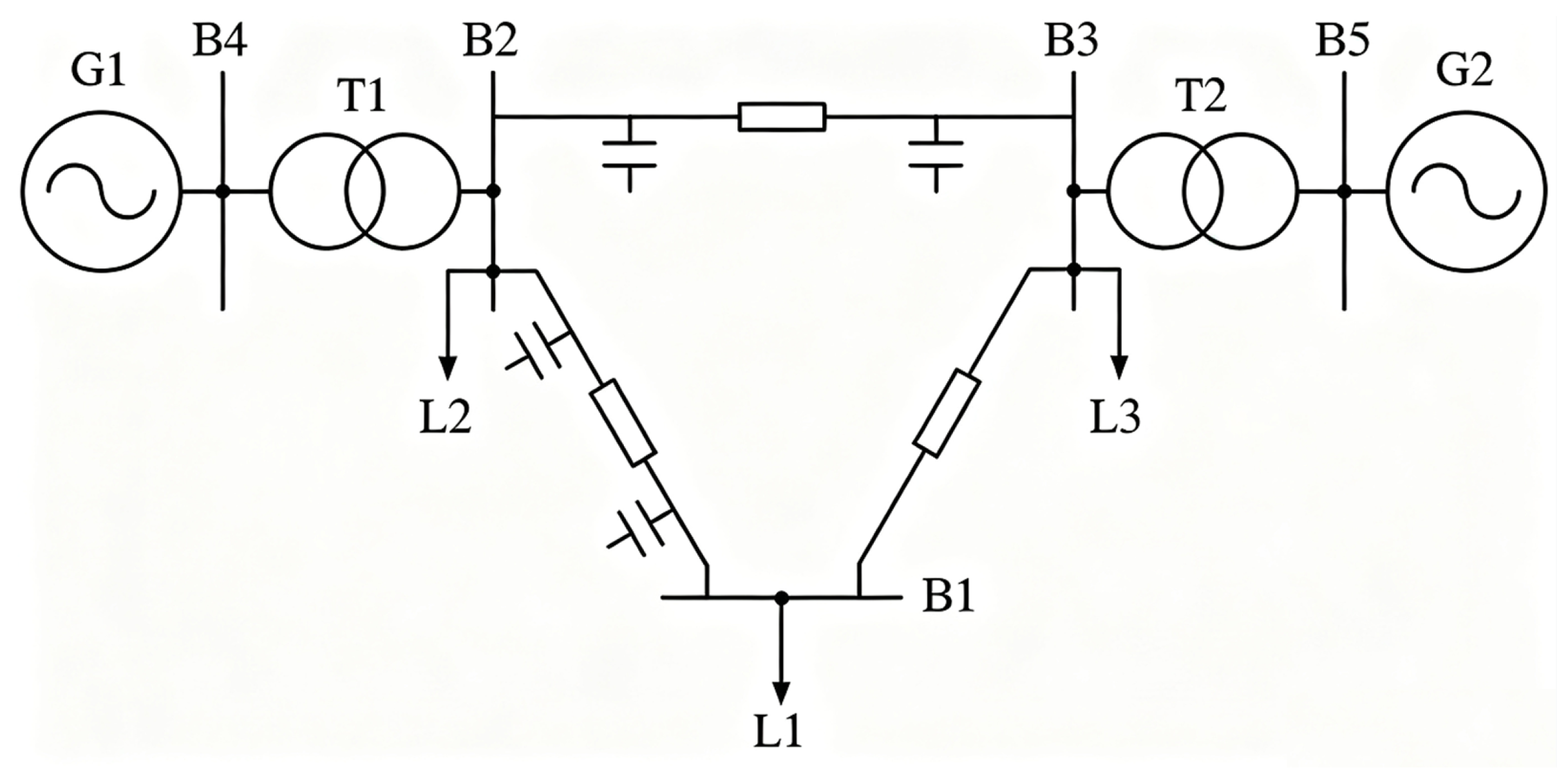
The case study uses the IEEE two-machine, five-node regional power-system model shown in Figure 1 to evaluate fast frequency regulation provided by VFAC loads.
Generators G1 and G2 are each rated at 100 MVA, while L1, L2, and L3 denote the load regions managed by three load aggregators. The VFAC loads are represented by the VSM cluster model, and the complete system is implemented in MATLAB/Simulink R2022b.
In the case study, thermal feasibility is enforced at the supervisory layer rather than embedded in the compressor-motor equations. The virtual-storage SOC in Section 4.3.3 represents the indoor-temperature margin within a 22–26 °C comfort band. Regulation commands are limited by the available charge/discharge power and duration, as well as by compressor operating limits, and the loads are restored gradually to mitigate rebound. The present Simulink study assumes ideal communication and local frequency measurement. Primary VSM action can use local frequency, reducing communication dependence, whereas communication delay or packet loss, measurement noise, cybersecurity issues, and hardware nonidealities remain practical limitations for future hardware-in-the-loop validation. Bounded J and positive D are used to preserve the intended closed-loop damping.

4.4.2. Primary Frequency-Regulation Simulation of the VFAC VSM Cluster

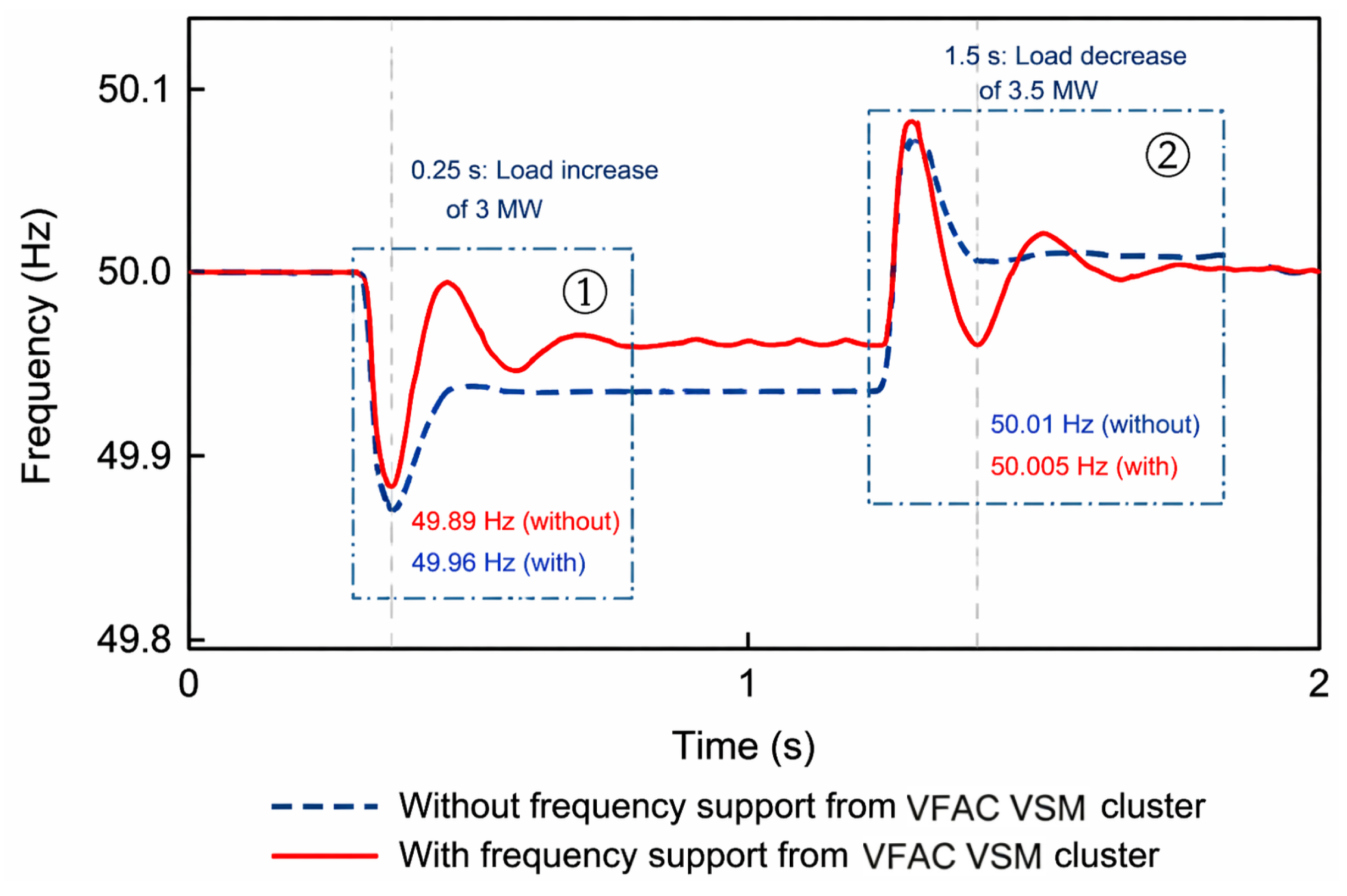
Only the load aggregator at L1 is assumed to participate in primary frequency regulation, and the frequency responses with and without VFAC support are compared. At L1, 5000 VFACs are available for regulation. The characteristic vector of each compressor motor is calculated from product specifications. Using the motor-aggregation method described in Section 4.1, these 5000 units are represented by two equivalent compressor motors. For this case study, c = 2 is selected to keep the equivalent model low order while retaining the main parameter heterogeneity of the compressor population. The resulting equivalent-motor parameters are listed in Table 2.
The 5000 operating VFACs are represented by two equivalent motor groups, and the group with the larger operating power is selected for primary frequency regulation. Load changes at L1 are then used to produce frequency deviations, with the corresponding responses shown in Figure 2. At 0.25 s, a 3 MW load increase causes the frequency to fall to 49.89 Hz without VFAC support; with VFAC regulation, it recovers to 49.96 Hz. At 1.5 s, a 3.5 MW load decrease raises the frequency to 50.01 Hz, after which VFAC regulation limits the steady value to approximately 50.005 Hz.
Using the simulated cluster-power response corresponding to Figure 2, the regulation energy is calculated as the time integral of the absolute power deviation from the pre-event operating point. The resulting regulation energy is approximately 1.08 kWh for the 3 MW load-increase event and 0.97 kWh for the subsequent 3.5 MW load-decrease event, quantifying the short-duration demand-side energy exchanged for primary frequency support.

4.4.3. Adaptive-Inertia Frequency-Regulation Simulation

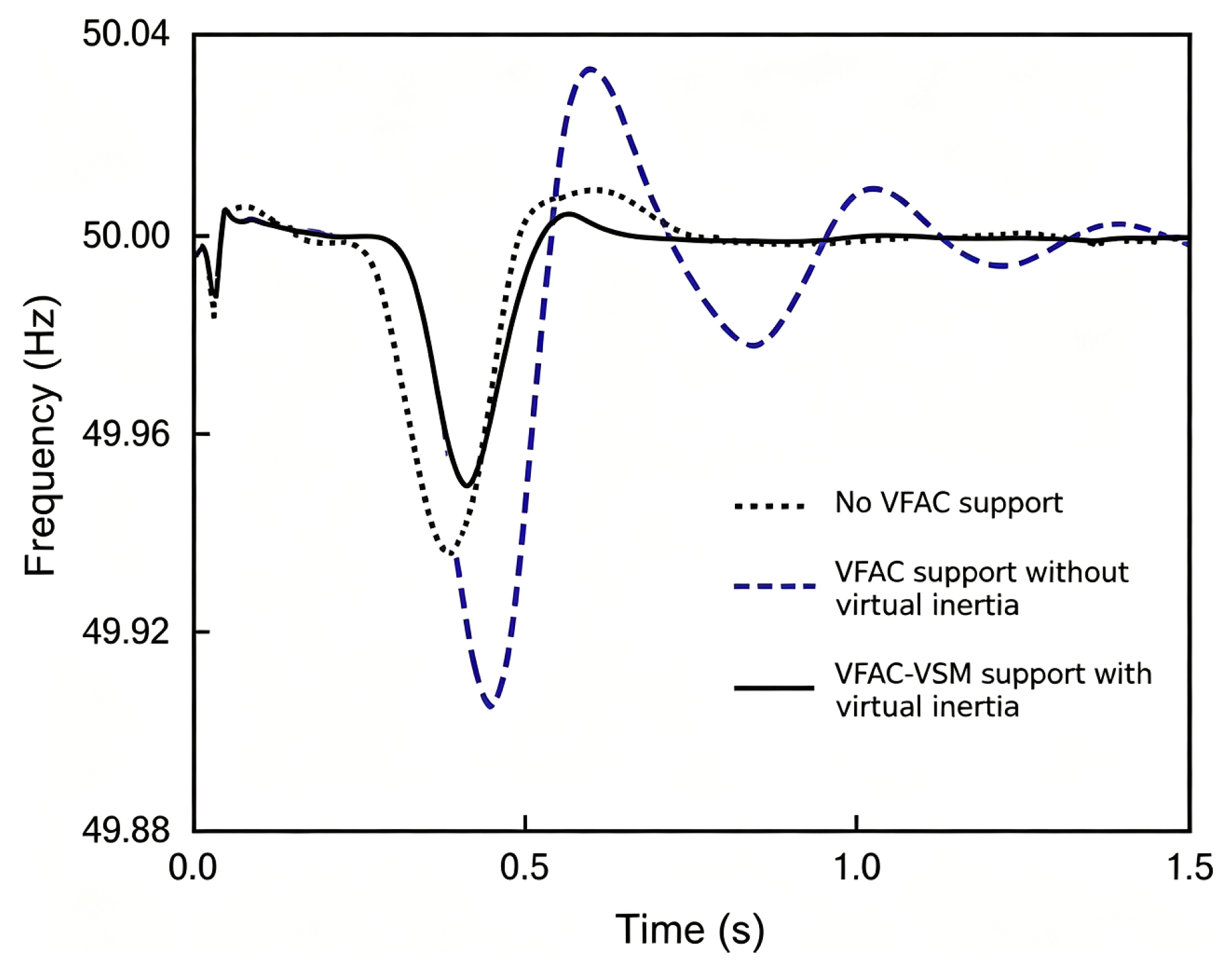
As analyzed in Section 4.3.2, the adaptive-inertia strategy is applied to the two-machine, five-node system. In the simulation, J is constrained to 0.2 ≤ J ≤ 0.9 according to Equation (19), and the resulting frequency response is shown in Figure 3.
Table 3 summarizes the frequency nadir, maximum absolute RoCoF, overshoot, and settling time obtained from the simulated responses. It compares the no-support case, a droop-only baseline without virtual inertia, two representative fixed-inertia VSM settings, and the proposed adaptive-inertia VSM. The maximum absolute RoCoF is calculated from the frequency derivative, and the settling time is defined as the time required for the response to remain within ±0.005 Hz of 50 Hz.
The fixed-inertia cases in Table 3 use D = 15 and illustrate the main inertia trade-off. Increasing J from 0.185 to 0.88 slows the initial response but results in a lower nadir, larger post-nadir overshoot, and longer settling time. The adaptive-inertia VSM provides the best overall balance among nadir, RoCoF, overshoot, and recovery speed. The intermediate J = 0.50 case follows the same trend. A damping-sensitivity study at J = 0.5 further shows that increasing D from 10 to 18.8 reduces oscillation amplitude and overshoot, although excessive damping slows the response. Mechanistically, the adaptive law provides stronger inertial buffering during rapid deviations and reduces inertia during recovery, while the damping term limits oscillatory power exchange.

4.4.4. Secondary Frequency-Regulation Simulation of VFAC VSM Clusters

When a large power deficit causes the frequency deviation to exceed the threshold for secondary regulation, the grid dispatch center issues a regulation command to the load aggregators. In the IEEE two-machine, five-node case, a short-circuit fault at G1 is used to create such a power deficit. The dispatch center then allocates the required regulation power to the aggregators at L1, L2, and L3. For simplicity, the air-conditioning loads controlled by each aggregator are represented by two VSM clusters. Their adjustable capacity, virtual-storage SOC, and allocated regulation power are listed in Table 4.
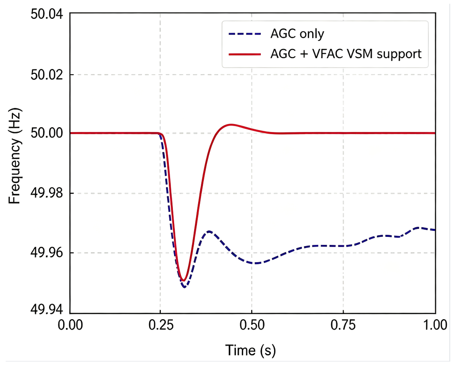
The VFAC VSM clusters controlled by each aggregator use the same VFAC parameters as in Section 4.4.2. The fault is applied at 0.25 s, and the resulting frequency response with secondary-regulation support is shown in Figure 4.
In Figure 4, “AGC only” denotes the generator-only baseline, whereas “AGC + VFAC VSM support” includes coordinated load-side support. At 1.0 s, the AGC-only case remains approximately 0.06 Hz below nominal, while the VFAC-assisted response has returned to about 50.00 Hz, indicating the benefit of coordinated demand-side support. Because post-event compressor rebound power is not directly reported in the present VSM frequency-regulation simulations, gradual load restoration is presented as a rebound-mitigation mechanism rather than as a quantitatively validated rebound-reduction result. This improvement arises from coordinating the available VFAC power as an additional controllable demand-side channel that complements generator AGC.

5. Conclusions

This study demonstrates the advantages of combining load-side VSM dynamics with FCM-based cluster aggregation and hierarchical coordination. The proposed framework enables continuous compressor-power modulation, scalable representation of large VFAC populations, adaptive shaping of the transient response, and coordinated primary/secondary frequency support. In the representative 3 MW load-increase case, the frequency deviation from nominal is reduced from 0.11 Hz to 0.04 Hz. In the secondary-regulation case, the VFAC-assisted response returns close to 50.00 Hz by 1.0 s, whereas the AGC-only response remains about 0.06 Hz below nominal. These results indicate improved simulated frequency response. Gradual load restoration is used as a rebound-mitigation mechanism, but quantified rebound reduction is not claimed in this study.
The main limitations are that thermal comfort is represented indirectly through virtual-storage SOC rather than by a detailed room-thermal model; communication delay, measurement noise, and packet loss are not quantitatively evaluated; validation remains simulation-based; and comparisons with alternative methods are limited to the selected baselines. Future work will incorporate more realistic building/VFAC thermal models and compressor constraints, communication nonidealities, broader benchmark comparisons, and hardware-in-the-loop or experimental validation.

Author Contributions

Conceptualization, T.G. and Y.C.; methodology, T.G. and J.D.; software, T.G.; validation, T.G., X.L., and J.Z.; formal analysis, S.L.; investigation, C.W.; resources, Y.C.; data curation, D.W.; writing—original draft preparation, T.G. and J.D.; writing—review and editing, Y.C.; visualization, X.L. and J.Z.; supervision, S.L.; project administration, S.L.; funding acquisition, Y.C. All authors have read and agreed to the published version of the manuscript.

Funding

This research was funded by the State Key Laboratory of Technology and Equipment for Defense against Power System Operational Risks, grant number SGNRGF00SXQT2501980.

Data Availability Statement

The original contributions presented in this study are included in the article. Further inquiries can be directed to the corresponding author.

Conflicts of Interest

Authors Tian Gao, Yonghua Chen, Shaohua Liu, Chuanxin Wen, De’an Wang, Xiang Li, and Jiatian Zhang are affiliated with Nari Technology Co., Ltd. The remaining author declare that the research was conducted in the absence of any commercial or financial relationships that could be construed as a potential conflict of interest.

References

  1. Dastgeer, G.; Nisar, S.; Zulfiqar, M.W.; Eom, J.; Imran, M.; Akbar, K. A review on recent progress and challenges in high-efficiency perovskite solar cells. Nano Energy 2024, 132, 110401. [Google Scholar] [CrossRef] [Scilit]
  2. Dastgeer, G.; Zulfiqar, M.W.; Nisar, S.; Zulfiqar, R.; Imran, M.; Panchanan, S.; Dutta, S.; Akbar, K.; Vomiero, A.; Wang, Z. Emerging Role of 2D Materials in Photovoltaics: Efficiency Enhancement and Future Perspectives. Nano-Micro Lett. 2026, 18, 32. [Google Scholar] [CrossRef] [Scilit] [PubMed]
  3. Short, J.A.; Infield, D.G.; Freris, L.L. Stabilization of Grid Frequency Through Dynamic Demand Control. IEEE Trans. Power Syst. 2007, 22, 1284–1293. [Google Scholar] [CrossRef] [Scilit]
  4. Lu, X.; Zhou, K.; Zhang, C.; Yang, S. Optimal load dispatch for industrial manufacturing process based on demand response in a smart grid. J. Renew. Sustain. Energy 2018, 10, 035503. [Google Scholar] [CrossRef] [Scilit]
  5. Yao, L.; Chang, W.-C.; Yen, R.-L. An iterative deepening genetic algorithm for scheduling of direct load control. IEEE Trans. Power Syst. 2005, 20, 1414–1421. [Google Scholar] [CrossRef] [Scilit]
  6. Lee, T.F.; Cho, M.Y.; Hsiao, Y.C.; Chao, P.J.; Fang, F.M. Optimization and Implementation of a Load Control Scheduler Using Relaxed Dynamic Programming for Large Air Conditioner Loads. IEEE Trans. Power Syst. 2008, 23, 691–702. [Google Scholar] [CrossRef] [Scilit]
  7. Hong, Y.Y.; Lin, J.K.; Wu, C.P.; Chuang, C.C. Multi-Objective Air-Conditioning Control Considering Fuzzy Parameters Using Immune Clonal Selection Programming. IEEE Trans. Smart Grid 2012, 3, 1603–1610. [Google Scholar] [CrossRef] [Scilit]
  8. Sinitsyn, N.; Kundu, S. Safe Protocols for Generating Power Pulses with Heterogeneous Populations of Thermostatically Controlled Loads. Energy Convers. Manag. 2012, 67, 297–308. [Google Scholar] [CrossRef] [Scilit]
  9. Yang, S.; Guo, N.; Zhang, S. Economic optimization of microgrid with demand response under source-load uncertainty. Energy Sources Part B Econ. Plan. Policy 2023, 18, 2280591. [Google Scholar] [CrossRef] [Scilit]
  10. Dalal, S.; Kumar Lilhore, D.; Seth, B.; Radulescu, M.; Hamrioui, S. A Hybrid Model for Short-Term Energy Load Prediction Based on Transfer Learning with LightGBM for Smart Grids in Smart Energy Systems. J. Urban Technol. 2024, 32, 49–75. [Google Scholar] [CrossRef] [Scilit]
  11. Ai, X.; Zhao, Y.; Zhou, S. Study on the virtual energy storage characteristics of direct load control for air conditioning loads. Proc. CSEE 2016, 36, 1596–1603. [Google Scholar]
  12. Hahm, S.-J.; Jang, Y.-E.; Kim, Y.-J. Virtual Battery Modeling of Air Conditioning Loads in the Presence of Unknown Heat Disturbances. Energies 2022, 15, 9354. [Google Scholar] [CrossRef] [Scilit]
  13. Zhu, X.; Wang, P.; Li, N.; Yan, W. Multi-period optimal scheduling of building loads based on accurate virtual battery model. Energy Build. 2025, 327, 115046. [Google Scholar] [CrossRef] [Scilit]
  14. Ding, M.; Yang, X.; Su, J. Control strategies of inverters based on virtual synchronous generator in a microgrid. Autom. Electr. Power Syst. 2009, 33, 89–93. [Google Scholar] [CrossRef]
  15. Pei, M.; Ye, L.; Luo, Y.; Sha, L.; Zhang, Z.; Song, X. Inertia estimation method for power system with renewable energy considering spatio-temporal correlation of frequency response. Autom. Electr. Power Syst. 2024, 48, 53–66. [Google Scholar] [CrossRef]
  16. Ai, P.; Lu, Z.; Zhou, S.; Chen, Q. Research on VSG control improved by Kalman filter. Mod. Electron. Technol. 2024, 47, 89–93. [Google Scholar]
  17. Zhao, B.; Zeng, J.; Xie, B.; Ma, H.; Liu, P.; Ye, K. New technology of grid harmonic impedance measurement based on photovoltaic inverter. Electr. Mach. Control Appl. 2024, 51, 1–9. [Google Scholar] [CrossRef]
  18. Kumar, T.V.; Thomas, V.; Kumaravel, S.; Ashok, S. Performance of virtual synchronous machine in autonomous mode of operation. In Proceedings of the 2018 5th International Conference on Renewable Energy: Generation and Applications (ICREGA), Al Ain, United Arab Emirates, 25–28 February 2018; pp. 310–314. Available online: https://www.semanticscholar.org/paper/Performance-of-virtual-synchronous-machine-in-mode-Kumar-Thomas/52c5b199c1c6ddd2691f687b133de122eadc810b (accessed on 17 August 2026). [CrossRef] [Scilit]
  19. Liu, J.; Miura, Y.; Ise, T. A Novel Oscillation Damping Method of Virtual Synchronous Generator Control Without PLL Using Pole Placement. In Proceedings of the 2018 International Power Electronics Conference (IPEC-Niigata 2018-ECCE Asia), Niigata, Japan, 20–24 May 2018; pp. 775–781. Available online: https://ieeexplore.ieee.org/document/8508003/authors#authors (accessed on 17 August 2026). [CrossRef] [Scilit]
  20. Baruwa, M.; Fazeli, M. The Role of Virtual Synchronous Machines in Future Power Systems: A Review and Future Trends. Electr. Power Syst. Res. 2022, 206, 107775. [Google Scholar] [CrossRef] [Scilit]
  21. Zhang, Y.; Zhang, X. Current status and prospects of virtual synchronous machine technology in renewable energy applications. Ind. Control Comput. 2020, 33, 117–120. (In Chinese) [Google Scholar]
  22. Li, B.-Y.; Du, X.-H.; Zeng, S.-M.; Yin, L.-K.; Rui, Y.-C.; Xiao, G.-C. Charge and discharge strategy based on load-side virtual synchronous machine for electric vehicles participating in grid frequency regulation and its realization. Adv. Technol. Electr. Eng. Energy 2021, 40, 11–22. [Google Scholar] [CrossRef]
  23. Hui, H.; Song, Y. Equivalence of inverter air conditioners as virtual synchronous generators for enhancing power system inertia and frequency stability. Energy Use 2025, 1, 100009. [Google Scholar] [CrossRef] [Scilit]
  24. Tang, X.; Tang, K.; Qu, B.; Zhou, X.; Zhou, Z.; Yu, Y. Analysis of dynamic and static coupling characteristics of power and decoupling methods for virtual synchronous generator grid connected system. Proc. CSEE 2026, 46, 2033–2045. [Google Scholar] [CrossRef]
  25. Tang, Y.; Hou, J.; Liu, W. The modeling of distribution network and VAR compensator and induction motor in the load model for power system digital simulation. Proc. CSEE 2005, 25, 8–12. (In Chinese) [Google Scholar]
  26. Cathey, J.J.; Cavin, R.K.; Ayoub, A.K. Transient Load Model of an Induction Motor. IEEE Trans. Power Appar. Syst. 1973, PAS-92, 1399–1406. [Google Scholar] [CrossRef] [Scilit]
  27. Zhang, S.; Liu, G.; Wang, W. Parameter identification method of variable-frequency air conditioner compressor motors. J. Power Supply 2013, 11, 95–100. (In Chinese) [Google Scholar]
  28. Deng, H. Research on Modeling and Control Strategy of Photovoltaic and Micro Gas Turbine Hybrid Microgrid. Master’s Thesis, Chongqing University, Chongqing, China, 2011. (In Chinese) [Google Scholar]
  29. Song, Q.; Zhang, H.; Sun, K.; Wei, Y. Improved Adaptive Control of Inertia for Virtual Synchronous Generators in Islanding Micro-grid With Multiple Distributed Generation Units. Proc. CSEE 2017, 37, 412–423. [Google Scholar] [CrossRef]
Figure 1. IEEE 2-machine, 5-node system architecture.
Processes 14 02726 g001
Figure 2. Primary frequency response of the VFAC VSM cluster.
Processes 14 02726 g002
Figure 3. Adaptive-inertia frequency response of the VFAC VSM cluster.
Processes 14 02726 g003
Figure 4. Secondary frequency response of the VFAC VSM clusters.
Processes 14 02726 g004
Table 2. Equivalent motor parameters for clustered variable-frequency air conditioner compressors.
Clustered Motor IDXs (Ω)X′r (Ω)Lm (H)Ja (kg·m2)s0 (-)
10.551 + j0.0640.557 + j0.0350.0490.0160.05
20.352 + j0.0280.425 + j0.0270.0300.0130.008
Table 3. Quantitative frequency-response metrics obtained from the simulation responses.
Control CaseNadir (Hz)Max |RoCoF| (Hz/s)Overshoot (Hz)Settling Time (s)
No support49.9360.720.0090.42
Droop-only baseline (no virtual inertia)49.9051.150.0331.01
Fixed-inertia VSM (J = 0.185)49.9410.810.0080.31
Fixed-inertia VSM (J = 0.88)49.9121.500.0320.94
Adaptive-inertia VSM49.9490.730.0040.26
Table 4. Frequency-regulation power allocation of aggregated VFAC VSM clusters.
Aggregator
(Allocated Power/Adjustable Capacity)
VFAC VSM ClusterAdjustable Capacity (MW)SOC (-)Allocated Power (MW)
L1 Aggregator
(4 MW/5 MW)
12.60.752.48
22.40.51.52
L2 Aggregator
(4.8 MW/6 MW)
33.70.73.13
42.30.61.67
L3 Aggregator
(3.2 MW/4 MW)
51.90.651.65
62.10.551.55
Disclaimer/Publisher’s Note: The statements, opinions and data contained in all publications are solely those of the individual author(s) and contributor(s) and not of MDPI and/or the editor(s). MDPI and/or the editor(s) disclaim responsibility for any injury to people or property resulting from any ideas, methods, instructions or products referred to in the content.