Article

Experimental and Numerical Investigation of Heat Transfer and Fluid Flow in Triply Periodic Minimal Surface Structures: Influence of Base Integration


Department of Mechanical and Industrial Engineering, Toronto Metropolitan University, Toronto, ON M5B 2K3, Canada
*
Author to whom correspondence should be addressed.
Processes 2026, 14(16), 2672; https://doi.org/10.3390/pr14162672
Submission received: 5 June 2026 / Revised: 25 July 2026 / Accepted: 7 August 2026 / Published: 21 August 2026

Abstract

This study investigates the heat transfer and fluid flow characteristics of six triply periodic minimal surface (TPMS) structures, specifically Gyroid (G3P6, G3P7, G3P8, G1P7) and Diamond (D1P7 and D3P7) configurations, using both experimental and numerical methods. Comparative analysis was conducted to evaluate the impact of adding a base to these structures on their thermal and hydraulic performance. The TPMS structures were assessed in terms of measured surface temperature, convection heat transfer coefficient, Nusselt number, overall thermal resistance, pressure drop, friction factor, and overall thermal–hydraulic performance. Results indicate that base-free structures exhibit better heat dissipation, with surface temperatures increasing by 1.2 °C (G3P6) to 5.5 °C (D3P7) when the base is added. The addition of the base reduces the convection heat transfer coefficient on average by 3.9% (G3P6) to 23% (D1P7) and increases overall thermal resistance by 3.1% (G3P6) to 28.7% (D1P7). The friction factor also rises by 6.1% (D1P7) to 47.3% (G3P6) due to the addition of the base. When the base is added, the overall thermal–hydraulic performance declines by 8.5% (G3P7) to 33.6% (D3P7), with Diamond structures experiencing a more significant reduction compared to Gyroid structures. Among the Gyroid structures, G3P6 (lower cell size and 60% porosity) demonstrated the lowest surface temperature and the highest heat dissipation capacity, while G3P8 (80% porosity) exhibited the lowest thermal performance. The Gyroid structure with larger cell size (G1P7) achieved the highest overall thermal–hydraulic performance, effectively balancing heat dissipation and fluid resistance. In contrast, when the base is integrated, the Gyroid structure with a smaller cell size and lower porosity (G3P6) showed the lowest overall thermal–hydraulic performance.

1. Introduction

In recent years, the investigation of Triply Periodic Minimal Surfaces (TPMSs) has received significant attention, particularly in heat transfer and fluid flow applications. TPMS structures, such as Gyroid and Diamond configurations, are characterized by unique geometrical properties, including high surface area-to-volume ratios and smooth curvature. These features make them suitable to improve the thermal performance of various engineering applications, such as heat sinks (in electronic cooling) and heat exchangers. TPMSs have advantages over traditional porous structures: it allows precise mathematical control over parameters like porosity and surface area; its exceptionally smooth design minimizes fluid resistance; and it effectively facilitates heat exchange between different fluids by creating two naturally separated flow channels (Qian et al. [1]). Moreover, these structures exhibit outstanding structural strength while minimizing material usage as stated by Li et al. [2,3]. As a result, TPMS structures have been investigated for various applications such as porous media by Jung & Torquato [4], sound absorbers by Yang et al. [5], filtration devices, mixers by Ouda et al. [6], tissue engineering scaffolds by Dong and Zhao [7] and concentrated solar power systems by Mortazavi et al. [8]. The TPMSs have also been studied for various thermal applications, including heat exchangers by Kaur and Singh [9]; Li et al. [3]; Attarzadeh et al. [10,11]; Dixit et al. [12]; Chen et al. [13]; Yan et al. [14]; El Khadiri et al. [15]; heatsinks by Al-Ketan et al. [16,17], battery thermal management by Du et al. [18]; Xiong et al. [19], and liquid cooling channels by You et al. [20]. Due to its highly increased surface area, TPMSs significantly enhance heat transfer performance compared to traditional heat exchangers by Yeranee and Rao [21]. Various research investigations revealed that the TPMSs have shown significant potential in improving the thermal performance of latent heat storage systems, such as Qureshi et al. [22], Zhang et al. [23] and Gado [24].
Many researchers have investigated the heat transfer and hydraulic performance of TPMSs. Cheng et al. [25] explored the morphology, flow, and heat transfer characteristics of typical TMPS-based porous structures. They utilized computational simulations to analyze the geometrical parameters and their impact on fluid flow and heat transfer within these structures. Morphological analysis was conducted to identify the relationships between geometric parameters and the performance characteristics of the TPMS structure. Their results revealed that the type P structure had the smallest flow resistance and highest comprehensive heat transfer coefficient. In another study, Tang et al. [26] performed experimentally verified numerical simulations to study the convective heat transfer performance of TPMS-based sheet structures consisting of Gyroid, Diamond, and Iwp. The authors compared the conventional fins-based heat sink. Their results indicated that the three TPMS models achieved higher convective heat transfer performance compared to the Fins model, albeit with increased flow resistance. The Diamond structure outperformed the others in convective heat transfer efficiency, followed by the Gyroid model, while the Iwp structure achieved the least effectiveness.
In their study, Qureshi et al. [22] utilized transient computational fluid dynamics simulations to evaluate the heat transfer performance of TPMS-based foams (specifically Gyroid, Primitive, and IWP) within a finned metal foam-phase change material (FMF-PCM) system. They compared these models against traditional Kelvin cell-based metal foams, assessing performance under both pure conduction and natural convection cases. The authors concluded that all TPMS-based metal foams outperformed their conventional counterparts, highlighting their potential for applications in thermal energy storage and thermal management systems.
Integrating TPMSs into heat exchangers can effectively address the limitations of area-to-volume ratios and traditional geometries, resulting in improved overall performance. In this regard, various researchers investigated TPMSs for heat exchanger applications (Li et al. [2,3]; Attarzadeh et al. [11]; Lesmana and Aziz [27]; and Min et al. [28]. To improve the heat transfer performance of heat exchangers in the supercritical carbon dioxide-based Brayton cycle, Li et al. [2,3] introduced two novel heat exchangers using TPMS structures: the Gyroid and Schwarz-D structures. The authors conducted a numerical comparison of these TPMS-based heat exchangers against printed circuit heat exchanger (PCHE). Their findings demonstrated that the TPMS-based designs improved the overall thermal performance and Nusselt number by 15–100% and 16–200%, respectively, compared to the PCHE. Attarzadeh et al. [10,11] performed a thermal analysis to investigate the performance of TPMS-based heat exchanger by modeling the Schwartz D structure. They concluded that the heat transfer performance is more effective if a Schwartz D lattice is used. TPMS structures show great potential as heat exchangers with extended surface properties per volume and reinforced structures designed to bear mechanical loads. As shown in their study, Lesmana et al. [27] indicated that TPMS structures exhibit significant promise as heat exchangers in metal hydride-based hydrogen storage due to their enhanced surface area-to-volume ratios and robust designs that can withstand mechanical loads. They proved that their proposed metal hydride-based hydrogen storage device offers higher hydrogen storage performance. Iyer et al. [29] reported that TPMSs can be utilized to design heat exchangers that offer enhanced performance, particularly in applications where space and weight are critical considerations. The authors showed that to dissipate the same amount of heat while operating under identical pressure conditions, the Schwarz-D-based heat exchanger was 3 to 10 times smaller than a conventional tubular heat exchanger. Min et al. [28] extensively evaluated the heat transfer performance across three hybrid and non-hybrid TPMS-based heat exchangers (HXs) through numerical simulations. Their findings indicated that the Gyroid–Diamond TPMS heat exchanger exhibited the highest heat exchange efficiency, reaching 37.78%. In addition, their study revealed significant improvements in the convective heat transfer coefficients for the Primitive–Gyroid and Primitive–Diamond heat exchangers, which increased by 47.31% and 67.38%, respectively, compared to the Primitive heat exchanger.
TPMS structures provide enhanced surface area and improved fluid flow, which can significantly boost thermal management. Various studies have shown that TPMSs offer a promising option for improving thermal management when used as a heat sink in various applications, such as in the cooling of electronic devices (Baobaid et al. [30]; Gado [31]). Using CFD models, Baobaid et al. [30] studied thermal performance and fluid flow characteristics of three TPMS-based heat sink designs (Diamond–Solid, Gyroid–Solid, and Gyroid–Sheet) under free natural convection conditions. The authors derived empirical correlations for the Nusselt number specific to the investigated TPMS structures. Their findings revealed that TPMS-based heat sinks outperform traditional heat sinks by 48–61%. They concluded that TPMS porous structures hold significant promise as effective heat sinks. Recently Gado [31] numerically studied heat transfer in the enhancement of electronic devices by using a heat sink that combines phase change material with Triply Periodic Minimal Surfaces (PCM-TPMSs). The author compared three PCM-TPMS heat sinks (PCM–Gyroid, PCM–IWP, and PCM–Primitive) against traditional pure PCM-based heat sinks. Their results indicated that the TPMS-based heat sinks significantly lowered the base temperatures of electronic components, achieving average values of 61.9 °C and 34.9 °C, in contrast to the higher temperatures recorded for pure PCM heat sinks under both passive and active cooling, respectively. They also reported that the use of PCM-TPMSs significantly enhances the reliability and durability of electronic components by mitigating thermal cycling.
Recent studies have extended TPMS heat-exchanger research toward practical geometric design, additive manufacturing, and thermal–hydraulic optimization. Zhang et al. [32] developed a conformal design method for special-shaped TPMS heat exchangers. They investigated Gyroid, Diamond, I-WP, and Primitive configurations using experimental and numerical approaches. They reported that their method benefits additive manufacturing and heat transfer capacities of additive manufacturing heat exchangers. The heat transfer efficiency improvements were achieved through their design methods. Dharmalingam et al. [33] presented thermal–hydraulic characterization and design optimization of TPMS-based heat exchangers for high-temperature and high-pressure applications. Their study showed that reducing the unit-cell hydraulic diameter increased surface-area density, leading to enhanced heat transfer. They proved that this approach is the most effective method of increasing heat transfer while maintaining a high level of HX compactness. Studies have also emphasized the importance of additive manufacturing quality in determining the thermal performance of TPMS heat exchangers. Reynolds et al. [34] experimentally investigated TPMS heat exchangers fabricated using different 3D-printing materials. They showed that manufacturing deviations in porosity and hydraulic diameter can significantly affect the calculated thermal–hydraulic characteristics. They reported that accurate characterization of the printed geometry is essential for reliable prediction of the Nusselt number, as deviations between the designed and manufactured structures could alter the calculated heat-transfer performance by up to 20%. These findings emphasize that besides topology and geometric parameters, manufacturing accuracy plays an important role in evaluating TPMS heat exchangers. However, their study focused primarily on manufacturing quality and heat-transfer characterization, whereas the present work investigates the influence of base integration on the thermal–hydraulic performance of Gyroid and Diamond TPMS structures with different porosities and unit-cell sizes.
Yu et al. [35] integrated data-driven optimization, additive manufacturing, and experimental testing to develop a high-temperature Gyroid-based TPMS heat exchanger. Their results showed that increasing the Gyroid frequency and reducing the iso-value enhanced heat transfer. However, these changes could also increase pressure drop, confirming the trade-off between thermal enhancement and hydraulic resistance. The optimized heat exchanger achieved 26.4% greater heat transfer and at least a 16% lower pressure drop than a conventional straight-pipe configuration. This study showed the importance of optimizing TPMS geometric parameters to obtain balanced thermal–hydraulic performance. More recently, Yanagihara et al. [36] investigated a TPMS Primitive heat exchanger with a spatially varied lattice distribution rather than a uniform structure. Using a macroscopic Darcy–Forchheimer flow model and a volumetric heat-transfer formulation, they optimized the lattice arrangement to improve the interaction between the hot and cold fluid streams. The optimized design achieved approximately 24.2% higher performance in detailed numerical simulations and 23.3% improvement in experiments compared with the uniform lattice. Their findings demonstrate that controlling the spatial distribution of TPMS geometry can improve flow distribution and overall heat-exchange performance. Zhang et al. [37] experimentally investigated additively manufactured flat-tube air-to-fluid heat exchangers incorporating Diamond, Gyroid, and IWP TPMS fins with the same porosity under simulated altitudes ranging from sea level to 4800 m. Their results showed that all TPMS configurations substantially enhanced heat transfer compared with conventional louvered fins, with Nusselt numbers approximately 93.8–307.4% higher. Among the investigated structures, the Gyroid heat exchanger achieved the highest coefficient of performance when heat transfer was evaluated relative to fan-power consumption, whereas the Diamond topology provided the best overall performance. Their results show that the TPMS topology highly affects the balance between heat-transfer enhancement and flow resistance, even at the same porosity. However, their study focused on topology selection and altitude effects in vehicle heat exchangers, while the present work evaluates the influence of base integration, porosity, and unit-cell size on Gyroid and Diamond cooling structures.
Despite the extensive research on TPMS structures for heat transfer and fluid flow applications, existing studies predominantly focus on numerical simulations, with limited experimental validation. While some previous work has studied the geometrical effect on thermal performance, few studies have systematically investigated the combined impact of geometric variations and base integration on TPMS structures. No prior study has investigated the effect of adding a base on key thermal–hydraulic parameters (such as heat dissipation efficiency, pressure drop, and overall thermal resistance). This study addresses this gap by conducting a detailed experimental and numerical investigation of six TPMS configurations (Gyroid: G3P6, G3P7, G3P8, G1P7) and (Diamond: D1P7, D3P7) with and without base integration. By comparing experimental results with numerical simulations, this research comprehensively evaluates the thermal and hydraulic performance of TPMS structures under varying geometric and boundary conditions. Furthermore, this research systematically evaluates the influence of base integration, offering valuable guidelines for designing TPMS-based heat sinks, heat exchangers, and cooling systems.

2. Experimental and Numerical Approaches

2.1. Experimental Methods

2.1.1. Experimental Setup

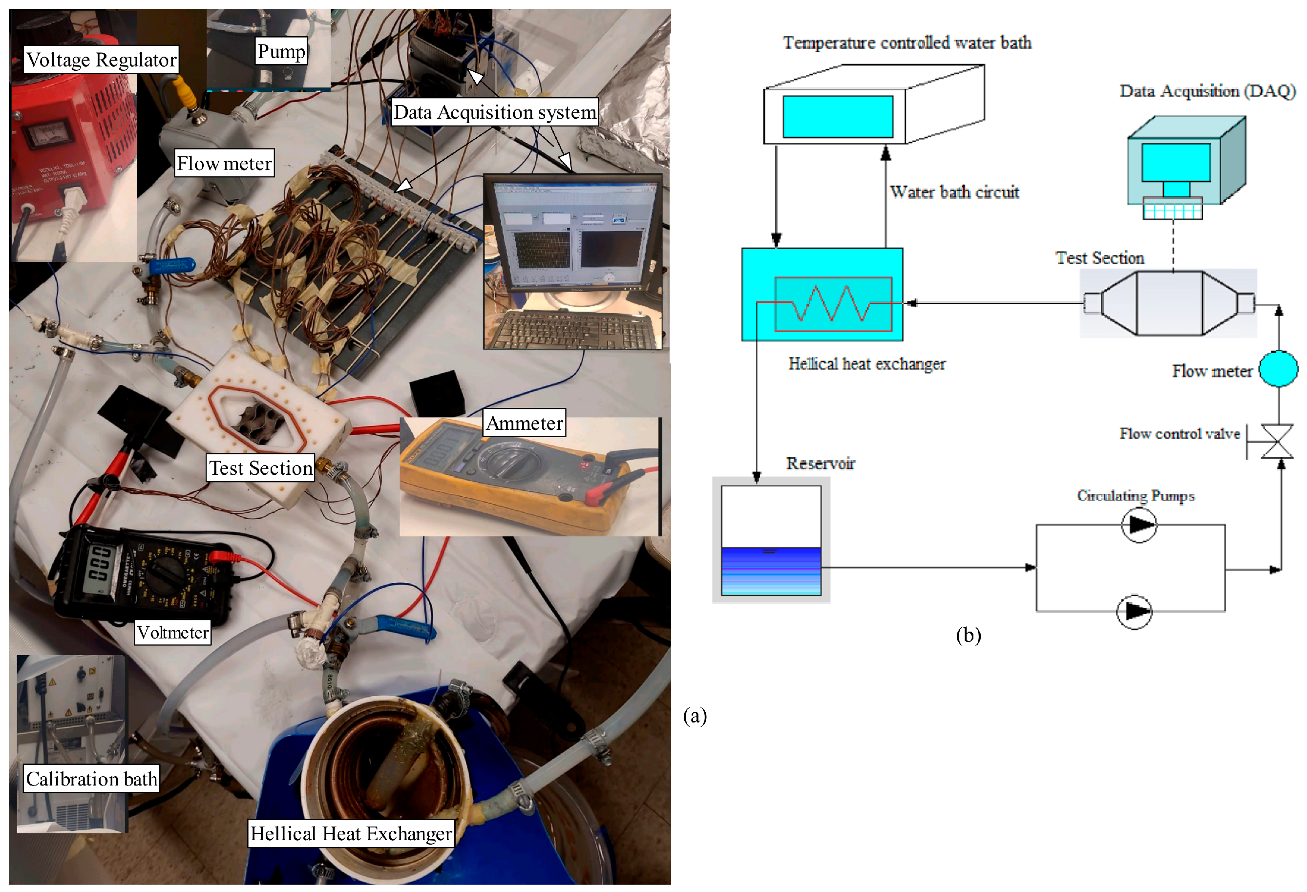
The experiment was conducted using an experimental apparatus consisting of several key components. These components include nine T-type thermocouples: seven to measure the surface temperature and two to measure the inlet and outlet temperatures of the working fluid. Additionally, a digital flowmeter, a calibration bath to maintain a uniform temperature at the fluid inlet, a helical coil heat exchanger, resistance-based heaters, circulating pumps, flow control valves, and a data acquisition (DAQ) system were utilized. Figure 1a provides a schematic diagram and further details of the experimental setup. The test section (where the sample was positioned) was intentionally designed to resemble a square plate. It had dimensions of 37.5 mm in width and length, with a height of 12.7 mm. This geometry was chosen to closely match the dimensions of an Intel i7 central processor, allowing for relevant comparisons and analysis. To provide a constant heat supply to the bottom surface of the Gyroid structure, a heater with adjustable voltage and current was used. The heat supply rate was determined by measuring the voltage and current outputs of the integrated voltage regulator using a voltmeter and an ammeter, respectively. This is done to provide a controlled and consistent heat supply during the experimental investigation.
The test section housing the Gyroid heat sink samples is constructed with high-quality Teflon insulation attached to the heater. This design minimizes heat loss, except for minor losses through the upper portion of the testing area, which is made of transparent plexiglass to allow the observation of the flow and the sample placement. To reduce the thermal contact resistance between each Gyroid sample and the heater surface, a thin layer of thermal paste was applied. The thermal paste used, SYY-157, is a metal-free and non-electrically conductive compound composed of carbon particles. This ensures no risk of short circuits and provides additional protection for the Gyroid heat sink sample. The thin layer of thermal paste also acts as a continuous connection between the top heater surface and the lower surface of the TPMS samples. The high thermal conductivity and performance of the applied thermal paste effectively dissipate the heat flux, ensuring efficient heat transfer from the heater to the samples.
The data acquisition system (DAQ) and LABVIEW software (version 2015) were used to capture and record data from the sensors in the experimental setup. This allowed for the measurement and display of key variables, such as temperature, flow rate, and other relevant parameters, throughout the experiment.

2.1.2. Experimental Procedure

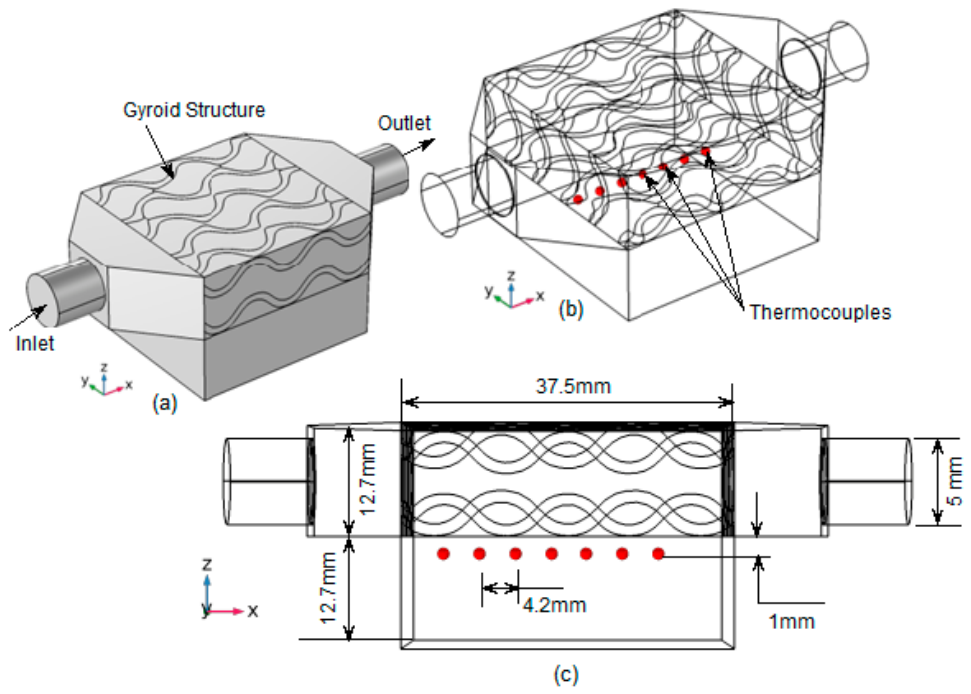
The experimental investigation began by placing the TPMS samples on the heater surface. The water in the water-bath circuit is then circulated until it reaches a steady-state temperature of 4 °C. Next, the test section is sealed, and distilled water in a separate circuit (distinct from the water-bath circuit) is circulated through the test section using dual parallel pumps. At this step, no heat flux is applied. To establish equilibrium conditions and maintain a constant inlet temperature, heat exchange occurs between the distilled water in the main circuit (containing the test section) and the water in the water-bath circuit (with a controlled temperature) through the helical heat exchanger. The achievement of a steady-state temperature for the working fluid is confirmed by monitoring the temperature profile generated by the data acquisition (DAQ) system. Once the distilled water in the main circuit reaches a steady-state temperature, a constant heating rate of 54.3 W, corresponding to a heat flux of 3.86 W/cm2, is applied by adjusting the voltage regulator integrated with a resistance-based heater. During the experimental investigation, the parameters adjusted and regulated include the voltage, current supply, and volume flow rate of the distilled water (used as the working fluid). Different measurements are taken, including the inlet and outlet temperature of the working fluid and the surface temperature along the test section. To measure and record the inlet and outlet temperature of the working fluid, the flow control valve is adjusted at different flow rates, with the flow rate being controlled using a control valve and digital flow meter. The surface temperature is measured using seven T-type thermocouples positioned just below the surface of the TPMS Gyroid structure. To prevent flow disturbances, the thermocouples were suitably placed 1 mm below the bottom surface of the sample, at intervals of 4.2 mm, 8.4 mm, 12.6 mm, 16.8 mm, 21.0 mm, 25.2 mm, and 29.4 mm.
Figure 1b illustrates the 3D layout of the Gyroid structure, its arrangement in the test section, the position of thermocouples, and the main dimensions in the test section. As previously mentioned, the flow rate is the controlled parameter during the experimental investigation. It is provided at five different levels: 3.92 cm3/s, 7.85 cm3/s, 11.78 cm3/s, 15.71 cm3/s, and 19.63 cm3/s. At each flow rate, the flow remains laminar, with the Reynolds number ranging from 242 to 711. To evaluate the heat transfer performance of the Gyroid structures, we applieda constant heat rate of 54.34 W corresponding to a voltage drop of 65 V and current supply of 0.836 A, at each flow rate mentioned above. Figure 2 shows the thermocouple locations for temperature measurement, and Figure 2a presents the model including the heater. Figure 2b shows the calculated temperature location, and Figure 2c shows the location of the measurement one experimentally.
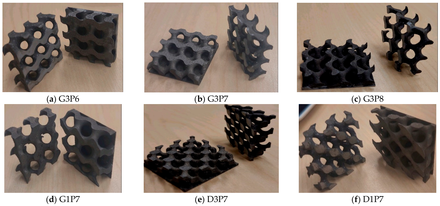
Figure 3 shows theinvestigated Gyroid and Diamond solid networks samples. The geometric characteristics of each investigated Gyroid and Diamond sample are illustrated in Table 1. The samples were designed with variation in unit cell size and porosity to achieve different surface areas for heat transfer. As shown in Table 1, we consider four Gyroid structures and two Diamond structures with different cell sizes and porosities. Table 1 also lists the calculated surface areas for each sample.
The MSLattice software in El Ketan et al. [17] was used to design a variety of uniform and graded cellular materials, emphasizing cell size to achieve different surface areas while maintaining a constant thickness. The 3D-printed samples were produced using the AlSi10Mg alloy, showing thermal conductivities ranging from 103 ± 5 to 119 ± 5 W·m−1·K−1 Kerme et al. [38] Fabrication was executed on the EOS M270 system, utilizing a 200 W laser with a scanning speed of 7 m/s and gas-atomized AlSi10Mg powder.
Figure 2. (a) The 3D layout of the Gyroid porous structure arrangement on the test section: (b) thermocouple positions and (c) main dimensions on the test section.
Processes 14 02672 g002
Figure 3. Investigated Gyroid and Diamond samples with and without base [17].
Processes 14 02672 g003

2.2. Numerical Approach

This paper uses COMSOL Multiphysics (version 6.2) to investigate the heat transfer and fluid flow performance characteristics of TPMS-based structures. The CFD techniques integrated with COMSOL model fluid flow and heat transfer within the TPMS-based structure, capturing complex flow patterns and temperature distributions. However, to ensure accurate and reliable predictions, it is essential to validate the numerical model by comparing simulation results with experimental measurements. In this regard, we validate the simulation results for surface temperature distribution and other relevant parameters against experimentally measured data in our lab. The numerical model solves the governing equations (the Navier–Stokes and energy equations).
Because the heat transfer occurs through the solid structure of the TPMS-based heat sink and the fluid (liquid water) passes through the heat sink, the conjugate heat transfer interface in COMSOL is utilized. This interface allows for the coupled simulation of heat transfer and fluid flow, enabling the modeling of the complex interactions between the solid and fluid domains. The complex Gyroid and Diamond structure of the TPMS-based heat sink necessitates the use of specialized solution techniques for the numerical simulation. As a result (to simplify the problem) a low flow rate is maintained, keeping the fluid flow in the laminar regime. As the water is the cooling medium, the flow is considered Newtonian, and a steady-state condition is adopted for the simulation.

2.2.1. Model and Boundary Conditions

In this study, the Gyroid and Diamond samples are solid networks of TPMS-based structures with varying porosities and cell sizes. The numerical model treats the Gyroid and Diamond structures as solids with specific porosities to permit fluid flow. To simulate the coupling of heat transfer and fluid flow, the model utilizes conjugate heat transfer, combining heat transfer in solids and laminar fluid flow. The model for these TPMS-based structures is formulated using governing equations of steady three-dimensional fluid flow and heat transfer. The continuity and momentum equations govern fluid flow, while the energy equation governs heat transfer. The governing equations for single-phase flow (assuming steady and incompressible flows) are presented in Equations (1)–(3):
The continuity equation:
u x + v y + w z = 0
Navier–Stokes equation in the x direction:
ρ f   u u x + v u y + w u z   = p x + μ f 2 u x 2 + 2 u y 2 + 2 u z 2  
Navier–Stokes equation in the y direction is given by:
ρ f u v x + v v y + w v z = p y + μ f 2 v x 2 + 2 v y 2 + 2 v z 2  
Navier–Stokes formulation in the z direction:
ρ f u w x + v w y + w w z = p z + μ f 2 w x 2 + 2 w y 2 + 2 w z 2 ρ f g β ( T T o )
The following equation provides the energy equation:
ρ f C p u T x + v T y + w T z   =   k f 2 T x 2 + 2 T y 2 + 2 T z 2
For the solid domain of the investigated TMPS-based structures, the steady-state heat conduction equation is provided by the following:
k s 2 T x 2 + 2 T y 2 + 2 T z 2 = 0
Equations (1)–(3) are utilized to model the fluid flow in the Gyroid and Diamond structure while the steady-state conduction heat transfer Equation (4) is applied to the solid part of the model (the Gyroid and Diamond structures as well as the heated block). The heat transfer and fluid flow are assumed to be steady, and the flow is incompressible. The simulations were performed assuming constant thermophysical properties for both the distilled water and the AlSi10Mg TPMS structures. Although the properties of water vary slightly with temperature, the experimental operating temperature range was relatively small, and therefore these variations have a negligible influence on the predicted heat transfer and pressure drop. Consequently, constant density, viscosity, thermal conductivity, and specific heat were adopted throughout the simulations. That is, all the physical properties of the working fluid (distilled water) were considered constant. The physical properties of the working fluid (water) can vary with temperature; however, this variation was insignificant in this study. Likewise, the thermal conductivity of the AlSi10Mg alloy was assumed constant because its variation within the investigated temperature range is insignificant.
The key boundary conditions used are as follows:
(i)
At the inlet, the velocity in the x-direction is set to a constant value, u = u i n . The fluid also enters the test section at a specified temperature, T = T i n .
(ii)
An open boundary condition at the outlet where the stresses are equal to zero was applied.
(iii)
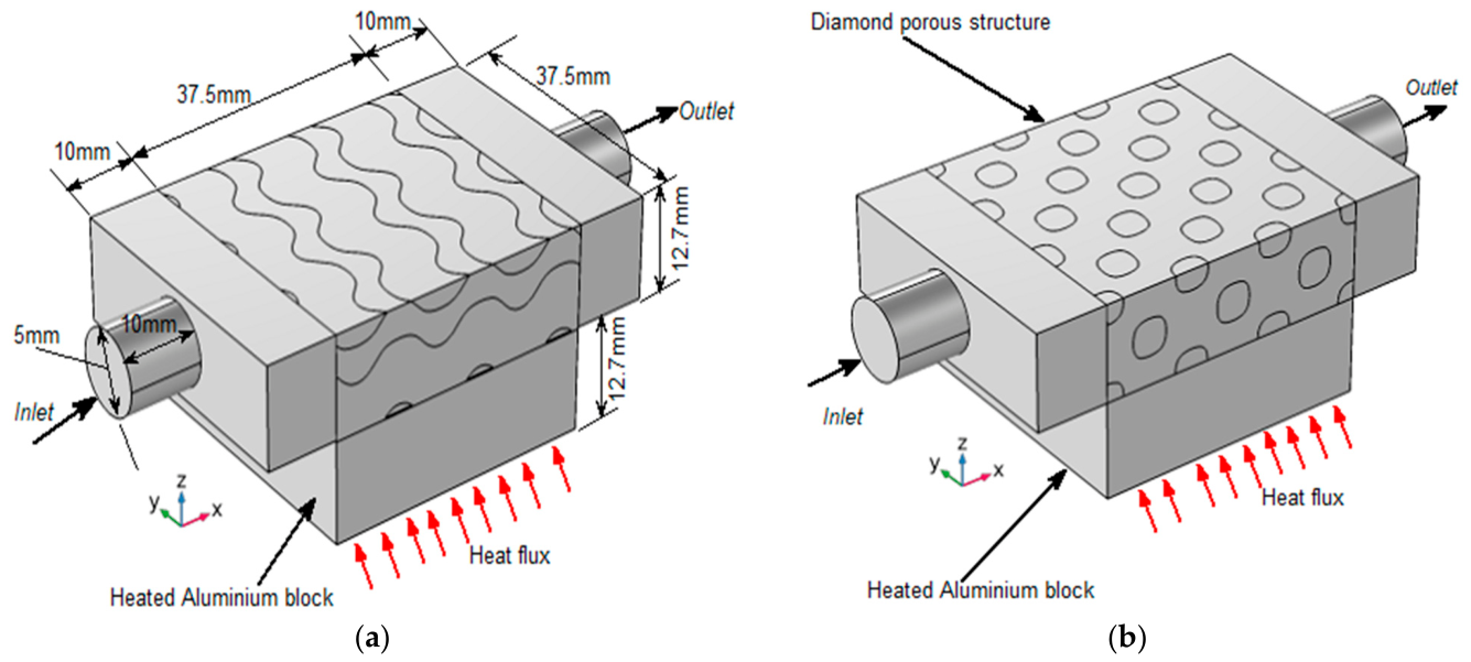
The bottom surface is heated with a constant heat flux ( q ). as illustrated in Figure 4.
(iv)
All other external surfaces are assumed to be adiabatic or insulated; that is, zero heat flux (∂T/∂n = 0).
(v)
The No-slip condition was applied at the solid–fluid interfaces.
In this study, COMSOL Multiphysics is applied to solve the governing Equations (1)–(4) presented in the previous section, considering the specified boundary conditions. The software utilizes a combination of finite element and segregated methods to accurately predict temperature distributions and pressure variations within the examined structures. The segregated approach is particularly advantageous for many Multiphysics problems, as it typically requires less memory and computational time compared to fully coupled methods. A solution is regarded as converged when the residuals of the variables (including pressure, temperature, and velocity) fall below 10−6 [39].
Figure 4. Schematics of computational domain and boundary conditions for (a) Gyroid structure (G3P7) and (b) Diamond structure (D3P7).
Processes 14 02672 g004
The governing Equations (1)–(3) were solved using the finite element method (FEM) implemented in COMSOL Multiphysics. The conjugate heat transfer interface simultaneously solves the Navier–Stokes equations for laminar fluid flow and the heat conduction equation in the solid domain, ensuring continuity of temperature and heat flux at the solid–fluid interface. A segregated solution approach was employed to solve the velocity–pressure and temperature fields sequentially, thereby reducing computational cost while maintaining numerical stability. Second-order discretization was adopted for both momentum and energy equations. The nonlinear governing equations were solved iteratively until the relative residuals for velocity, pressure, and temperature were below 10−6. Mesh independence was verified prior to performing all simulations to ensure that the predicted temperature distribution and pressure drop were independent of mesh resolution.
Furthermore, the numerical model assumes hydraulically smooth walls because the surface roughness of the additively manufactured samples is relatively small compared with the hydraulic diameter of the flow passages. To ensure continuity of heat flux and temperature across the solid–fluid interface, heat transfer between the solid TPMS structure and the working fluid was modeled using the conjugate heat transfer interface. The authors minimized thermal contact resistance between the heater and TPMS samples experimentally using a thin layer of high-conductivity thermal paste and was therefore neglected it in the numerical model. Thermal radiation was also neglected because the experiments were conducted under relatively low operating temperatures and forced liquid cooling, where radiative heat transfer contributes only a very small fraction of the total heat transfer.

2.2.2. Mesh Generation and Sensitivity

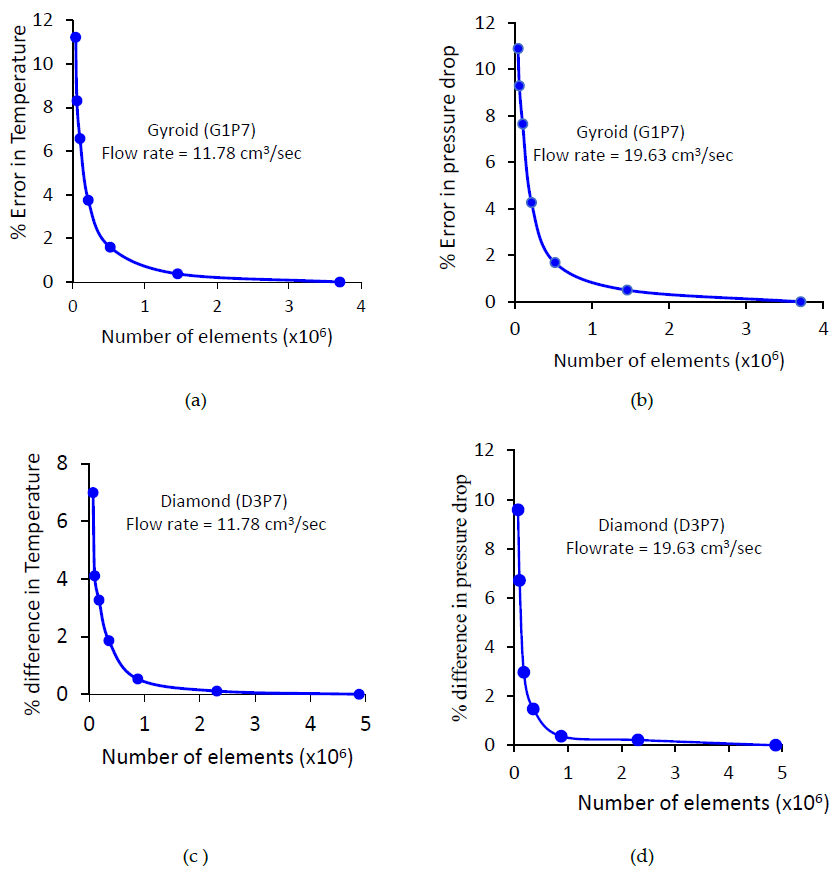
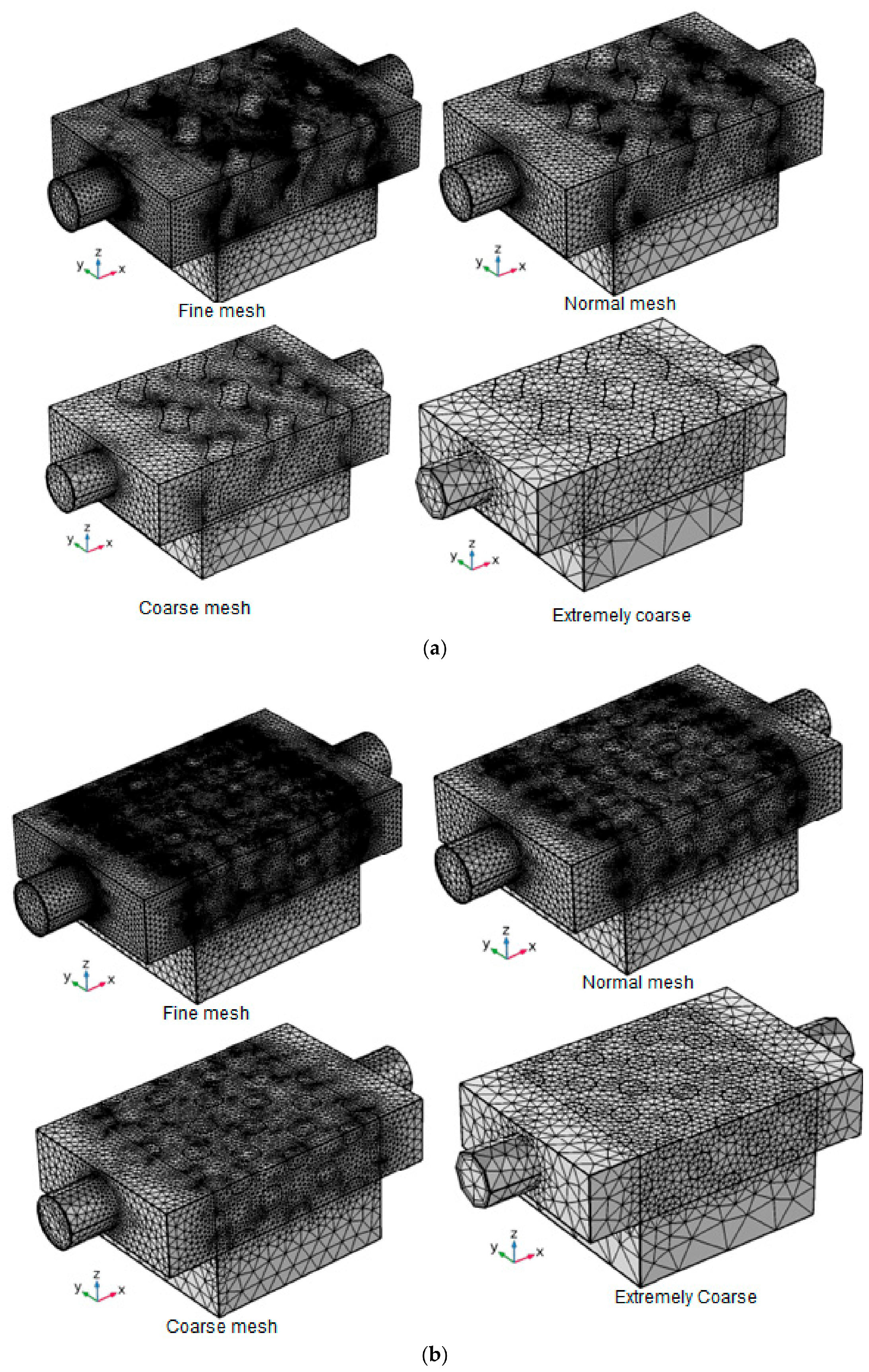
Mesh generation and mesh sensitivity analysis are important for accurate and efficient simulations and analysis. Mesh-independent analysis in COMSOL involves refining the mesh and observing the change in simulation results until we get an optimal mesh for our geometry and analysis. To obtain mesh-independent results, we performed analyses of maximum surface temperature and pressure drop at two flow rates (11.78 and 19.68 cm3/s) across varying mesh levels for the Gyroid structure (G1P7) and Diamond structure (D3P7). Figure 5 presents the results. Using a fine mesh, detailed calculations indicate that for the Gyroid structure (G1P7) and Diamond structure (D3P7), the percentage error in temperature was 0.38% and 0.112%, respectively, at a flow rate of 11.78 cm3/s. Similarly, the percentage error in pressure drop (calculated at a flow rate of 19.63 cm3/s) is 0.50% and 0.215%, respectively, for G1P7 and D3P7. Though the finer mesh level provides the lowest error, it was not taken for the current analysis as it results in high computational time. The fine mesh was determined as an optimal mesh; therefore, all the current analyses were done using fine mesh. The grid numbers determined for G1P7 and D3P7 are 1,455,101 and 2,308,816, respectively. Similarly, the number of elements for the other remaining structures was calculated. The different mesh levels generated for the Gyroid and Diamond samples are indicated in Figure 6a,b.
Different parameters, including the Nusselt number, convection heat transfer coefficient, overall thermal resistance, friction factor, and Colburn ratio, are utilized to analyze the thermohydraulic performance of the investigated Gyroid and Diamond samples. This section provides these parameters along with their respective equations.
The local Nusselt number ( N u x ) and local convection heat transfer coefficient ( h u x ) are determined by the Equations (5) (a) and (5) (b), respectively.
w h e r e ,   N u x = h x   d H k a d H = 4 A P b h x = q T x T b c
The channel hydraulic diameter ( d H ) of the TPMS sample is defined in Equation (5) (b) in terms of cross-sectional area (A) and wetted perimeter (P) at the inlet of the TPMS sample. That is, the hydraulic diameter was determined by considering the width (37.5 mm) and height (12.7 mm) at the inlet of the sample. This results in a value of 18.97 mm. Moreover, in Equation (5) (c), q represents the constant heat flux supplied at the base of each TPMS sample. It is determined by dividing the heat transfer rate provided by the heater (54.34 W) to the base area of the Gyroid/Diamond sample (37.5 mm × 37.5 mm). The variables Tx and Tb represent the local surface temperature and bulk fluid temperature (average of the inlet and exit temperature of the working fluid), respectively. The T-type thermocouples measure the surface temperature, fluid inlet, and outlet temperature.
The average Nusselt number ( N u a v ) , calculated based on the average heat transfer coefficient ( h a v ) , is defined by Equation (6) (a):
N u a v = h a v   d H k   a h a v = q   T a v T b   b  
In Equation (6) (b), the average convection heat transfer coefficient ( h a v ) for each TPMS sample is determined based on the heat flux applied and the average bottom surface temperature ( T a v ) and bulk fluid temperature ( T b ).
The paper also assesses the overall thermal resistance. Determining the overall thermal resistance of a TPMS-based heat sink is essential for different purposes. It enables us to evaluate how effectively the heat sink can dissipate thermal energy. Lower thermal resistance indicates better heat transfer performance, improving the TPMS-based heat sink’s cooling efficiency. Comparing the overall thermal resistance values across different TPMS-based heat sinks allows us to choose the most effective design for different specific cooling applications. The following equation determines the overall thermal resistance
R T = T a v T i n Q ˙
where Q ˙ is the rate of heat supplied by the heater, and T i n is the inlet temperature of the working fluid.
The Colburn factor (j) and friction factor (f), which represent dimensionless heat transfer and flow resistance performance, are defined by Equations (8) (a) and (8) (b), respectively.
j = N u R e P r 1 / 3   ( a ) f = P d H 2 ρ f   L   u 2   ( b )
where P and ρ f are the pressure drop between the inlet and outlet, and the density of the distilled water, respectively. In Equation (8), Pr and Re are the Prandtl and Reynolds numbers, d H is the channel hydraulic diameter of the TPMS sample, u is the fluid velocity (m/s), and L is the length of the sample.

3. Results and Discussion

In this section, a comprehensive analysis of the heat transfer and fluid flow performance of various Gyroid and Diamond structures is presented. The geometric characteristics of the investigated TPMS structures are as detailed in Table 1. The variation of different key parameters, including surface temperature, convection heat transfer coefficient, Nusselt number, overall thermal resistance, pressure drop, friction factor, and the ratio of Colburn factor to friction factor, as a function of flow rates will be presented. In addition, the impact of adding a base to the samples on their heat transfer and fluid flow performance will be studied by making a comparative performance analysis between TPMS structures with and without the base. Experimental results for six samples, whose geometric characteristics are shown in Table 1 and illustrated in Figure 3, are compared and discussed. Furthermore, numerical analyses of temperature distribution, pressure drop, and fluid flow are presented to complement the experimental findings. The numerical results are validated against experimental data to ensure their accuracy and reliability.

3.1. Experimental Results and Discussion

3.1.1. Comparison of Structure with and Without Base

The ability to compare TPMS structures with and without a base allows for customization based on specific needs. For example, in applications where structural stability is more critical than heat transfer efficiency, a base might still be preferred despite its impact on heat transfer. Performance comparison between the TPMS structure with base and without was made to understand how the addition of a base affects the heat transfer and fluid flow characteristics of the TPMS-based structures. For all six samples (presented in Table 1 and Figure 3), comparison was made in terms of surface temperature, convection heat transfer coefficient, Nusselt number, overall thermal resistance, pressure drop, friction factor, and the ratio of Colburn factor to friction factor.
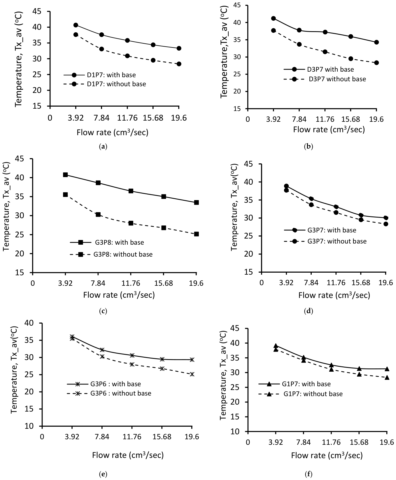
To compare the heat transfer performance between the TPMS structures with base and without base, a constant heat rate of 54.34 W (corresponding to a voltage drop of 65 V and a current of 0.836 A) was applied at the bottom of each sample. Flow rate was the controlled parameter during the experimental investigation. For each sample, the flow rate was kept at five different levels: 3.92 cm3/s, 7.85 cm3/s, 11.78 cm3/s, 15.71 cm3/s, and 19.63 cm3/s. The surface temperature was then measured using T-type thermocouples positioned just below the surface of each TPMS structure. For each flow rate, the flow remains within the laminar regime, resulting in the Reynolds number varying between 242 and 711. To prevent flow disturbances, the thermocouples were suitably placed 1 mm below the bottom surface of the Gyroid structure, at intervals of 4.2 mm, 8.4 mm, 12.6 mm, 16.8 mm, 21.0 mm, 25.2 mm, and 29.4 mm. Figure 7 shows the variation of measured surface temperature as a function of flow rate for all the six investigated structures with base and without base. In all six samples, the surface temperature of the structure with the base was higher than that without a base. Adding the base resulted in an average increase in surface temperature of 2.9 °C, 1.3 °C (3.9%), 1.2 °C, 1.7 °C, and 4.5 °C for G3P8, G3P7, G3P6, G1P8, D3P7, and D1P7, respectively. This shows that when the same amount of heat is supplied, the structure without a base dissipates more heat from its surface than the structure with a base. The base adds a layer of material, increasing the overall thermal resistance. This means that heat must pass through more material before dissipating, leading to higher surface temperatures. Moreover, the structure without a base has more surface area directly exposed to the cooling medium, water. This allows for more efficient heat transfer away from the structure, resulting in lower surface temperatures. In contrast, the base reduces the exposed surface area, limiting heat dissipation, and hence resulting in a higher surface temperature.
In the preceding discussion, we compared TPMS structures with and without a base based on measured surface temperatures. However, surface temperature alone does not provide a better understanding of the heat transfer performance between these configurations. For a more comprehensive evaluation, it is important to consider additional parameters. In this regard, we evaluated the convection heat transfer coefficient and Nusselt number for each investigated structure.
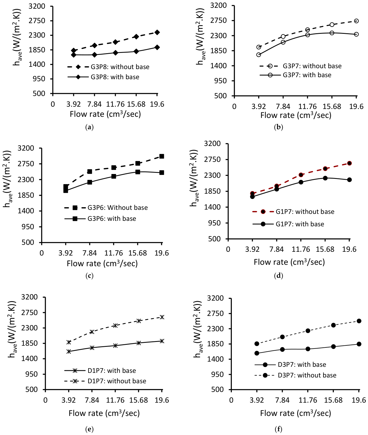
The convection heat transfer coefficient is essential for understanding how effectively heat is transferred from the surface of the Gyroid or Diamond structure to the surrounding fluid. This parameter was calculated for each structure and illustrated in Figure 8 as a function of flow rate. The results indicate that, for each structure, the convection heat transfer coefficient of the samples with a base is lower than that of those without a base. Specifically, adding the base reduces the convection heat transfer coefficient by 5.4% to 38%, 6.5% to 17%, 5.5% to 12.5%, 4.7% to 21.5%, 17.7% to 36.9%, and 16.8% to 36.4% for G3P8, G3P7, G3P6, G1P7, D3P7, and D1P7, respectively. On average, the convection heat transfer coefficient is reduced by 15.6%, 8.9%, 3.9%, 9.8%, 22.5%, and 23% for G3P8, G3P7, G3P6, G1P7, D3P7, and D1P7, respectively. These results indicate that adding the base has a more significant impact on the performance of Diamond structures compared to Gyroid structures. The TPMS structure with a base has a lower convection heat transfer coefficient due to several factors. The base can impede the fluid flow, creating a boundary layer that increases thermal resistance. This boundary layer reduces the effective surface area available for heat transfer and disrupts the fluid dynamics, leading to less efficient convective heat transfer. Additionally, the base can cause flow separation and recirculation zones, further diminishing heat transfer performance. These factors collectively result in a lower convection heat transfer coefficient for TPMS structures with a base than those without a base.
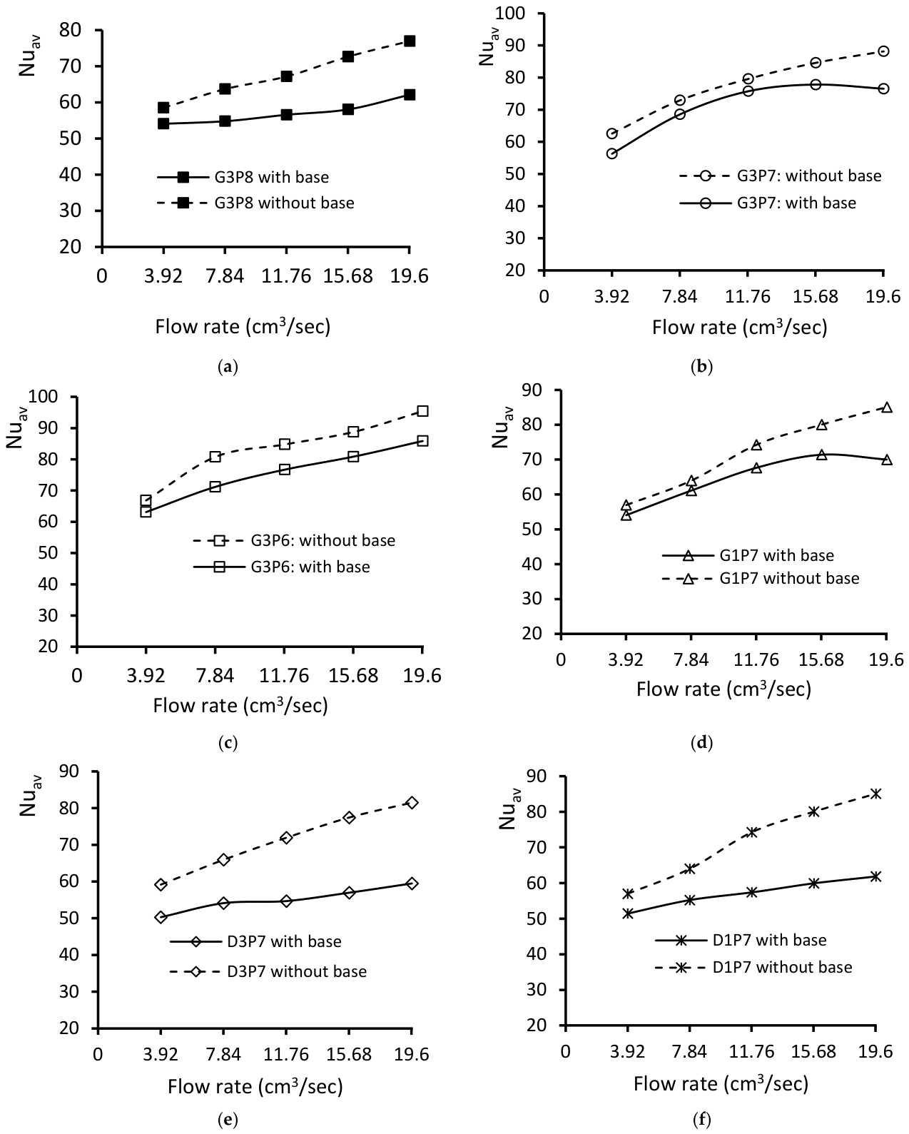
Another important parameter analyzed in this study is the Nusselt number, which enables us to quantify the heat transfer efficiency of the Gyroid and Diamond structures. It helps in understanding how effectively heat is being transferred from the surface of the structure to the surrounding fluid—in this case, water. By evaluating the Nusselt number, the heat transfer performance of different TPMS structures can be compared. This comparison is important to identify the configuration that offers superior thermal performance, aiding in the selection of the most efficient design for specific applications. The Nusselt number was evaluated for each Gyroid and Diamond structure with base and without base. The obtained result is presented in Figure 9 with the Nusselt number as a function of flow rate. For all the Gyroid and Diamond samples, the Nusselt number of the structure without a base has a higher Nusselt number than that with the base. The result obtained indicates that adding the base reduced the Nusselt by 5.4% to 38%, 6.5% to 17%, 5.5% to 12.5%, 4.7% to 21.5%, 17.7% to 36.9%, and 16.8% to 36.4% for G3P8, G3P7, G3P6, G1P7, D3P7, and D1P7, respectively. On average, the convection heat transfer coefficient is reduced by 15.6%, 8.9%, 3.9%, 9.8%, 22.5%, and 23% for G3P8, G3P7, G3P6, G1P7, D3P7, and D1P7, respectively. The structure without a base has a higher Nusselt number due to enhanced fluid flow dynamics and reduced thermal resistance. Without a base, the fluid can flow more freely around the structure, promoting better mixing and higher convective heat transfer. The absence of a base minimizes flow obstructions and boundary layer formation, leading to more efficient heat transfer from the surface to the fluid. This results in a higher Nusselt number, indicating more effective convective heat transfer in TPMS structures without a base. For applications requiring efficient thermal management, such as in heat exchangers, cooling systems, and electronic devices, these findings suggest that TPMS structures without a base may be more effective. This can lead to the development of more efficient cooling solutions that utilize better heat transfer capabilities of base-free TPMS structures.
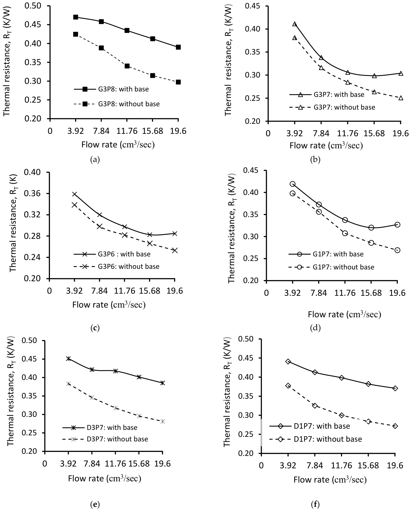
Another important parameter evaluated is the overall thermal resistance. Assessing this parameter alongside the previously discussed parameters is essential for a comprehensive understanding of the thermal performance of the investigated TPMS structures. Evaluating thermal resistance allows us to determine how effectively the Gyroid and Diamond-based TPMS structures can dissipate heat applied at the bottom of each structure. Thus, investigating overall thermal resistance in the context of TPMS structures is essential to know how these complex structures dissipate heat and maintain optimal operating temperatures in various applications, particularly as heat sinks in electronic cooling. The thermal resistance was evaluated for all investigated Gyroid and Diamond structures, both with and without bases, as illustrated in Figure 10. The results indicate that in all six samples examined, the structures with bases exhibited higher thermal resistance compared to those without bases. This suggests that when subjected to the same amount of heat, the structures with bases dissipate less heat from their surfaces. The additional layers of material introduced by the base increase the thickness through which heat must pass, resulting in greater thermal resistance. Thus, the analysis revealed that incorporating the base into the structures led to an increase in overall thermal resistance for each configuration, as follows: G3P8 (18% to 45%), G3P7 (14.4% to 25.4%), G3P6 (6% to 18.6%), G1P7 (4.7% to 21.5%), D3P7 (17.7% to 37%), and D1P7 (16.7% to 36.4%). The addition of the base results in an average increase in overall thermal resistance of 22.7%, 10%, 3.1%, and 9.1% for G3P8, G3P7, G3P6, and G1P7, respectively, while for Diamond structures (D3P7 and D1P7) the increases are 27.9%, and 28.7%, respectively. These results show the varying impact of the base on different structures, with Diamond structures experiencing a more significant increase in thermal resistance compared to Gyroid structures.
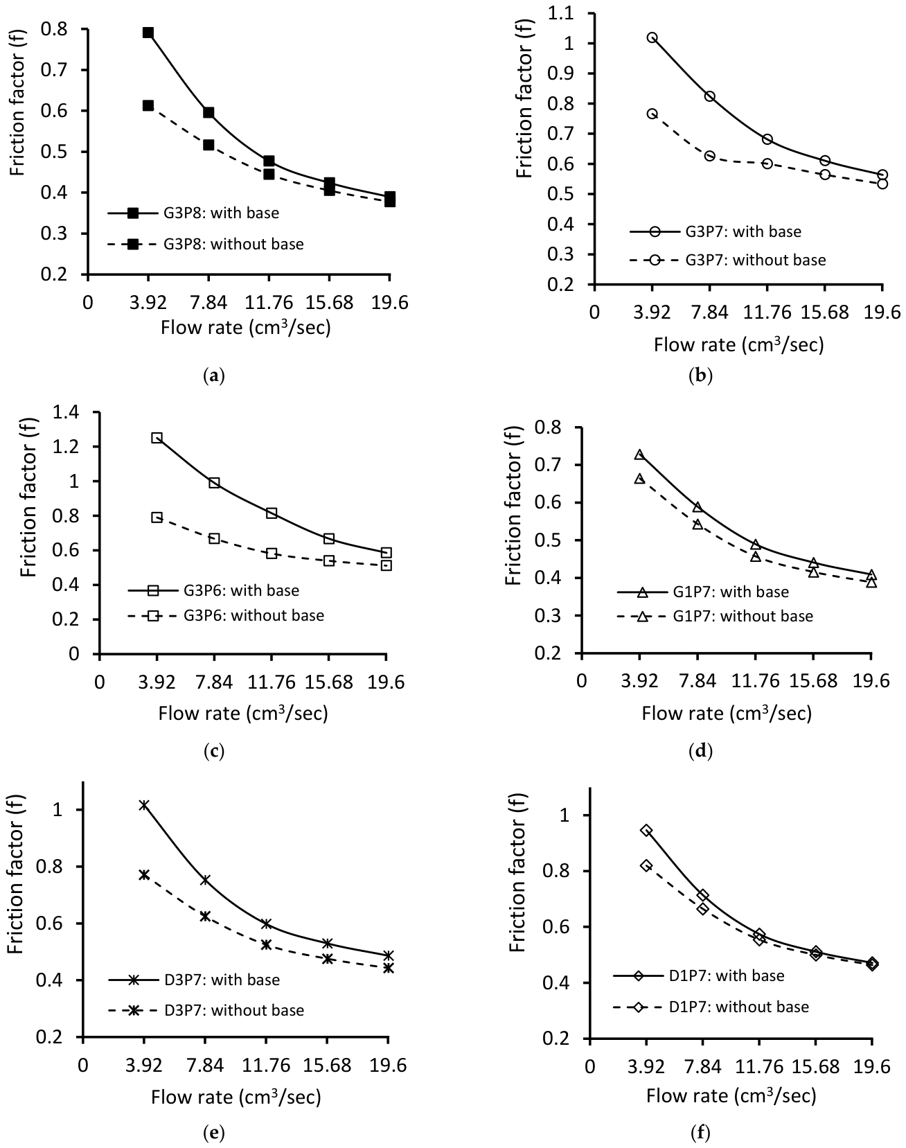
In addition to thermal performance, we also evaluated the hydraulic performance of each structure, both with and without its base. The friction factor, which indicates pressure drop, was evaluated for all examined Gyroid and Diamond structures, as illustrated in Figure 11. The results revealed that the structures with a base exhibited a higher friction factor compared to those without a base. The difference between friction factors is highest for a low flow rate and lowest for a high flow rate.
The difference in friction factors between different TPMS structures (with base and without base) is most pronounced at low flow rates and diminishes at higher flow rates. For the various configurations examined, adding the base resulted in increasing the friction factor, with a percentage increase ranging from 3.2% to 29.2% for G3P8, 5.6% to 33% for G3P7, 2.6% to 155% for G3P6, 5.3% to 9.6% for G1P7, 9.8% to 31.8% for D3P7, and 1.6% to 15.4% for D1P7. On average, adding the base resulted in an 11.9% increase in friction factor for G3P8, 18.4% for G3P7, 47.3% for G3P6, 7.3% for G1P7, 17.5% for D3P7, and 6.1% for D1P7. These results show the impact that adding the base has on the frictional characteristics of the TPMS structure. Different factors contribute to the increased friction factor when a base is added to the samples. First, the additional layers of material in the base increase the surface area for fluid interaction, leading to greater viscous drag. Second, the thicker geometry of the base can disrupt the smooth fluid flow, increasing turbulence and consequently the friction factor. The presence of a base can also introduce more complex flow paths, causing additional resistance to fluid movement, and hence, additional pressure losses. Furthermore, the base can enhance boundary layer development, which increases the overall resistance to flow.
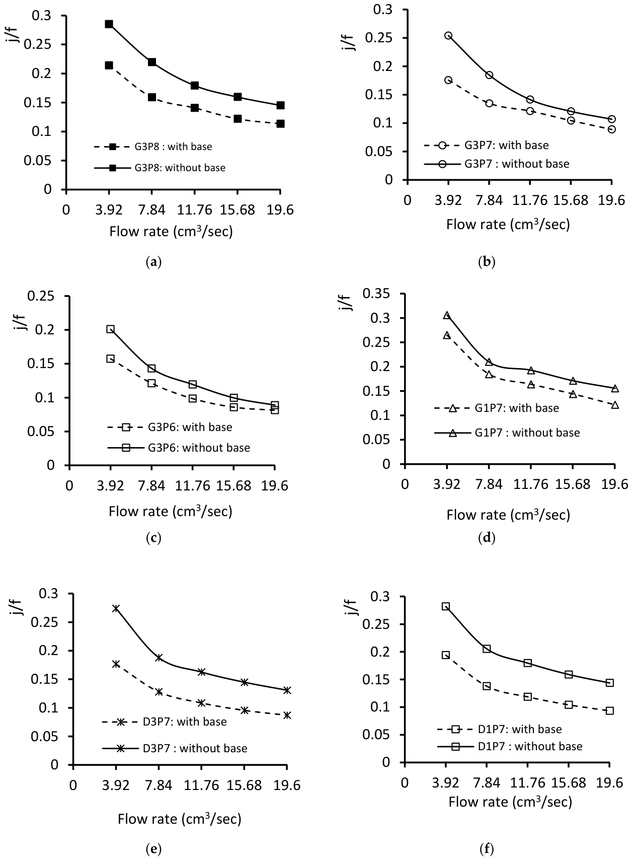
Finally, we analyzed the overall thermal–hydraulic performance of all structures. A comparison was made between the configurations with and without the base, focusing on the overall performance parameter. To assess this performance parameter, we utilized the ratio of the Colburn factor to the friction factor (j/f), which provides a comprehensive evaluation of heat transfer efficiency and pressure drop characteristics. The results of the comparison between structures with and without a base for each investigated Gyroid and Diamond structure are illustrated in Figure 12. For all the samples, the overall performance of the structure with the base is lower than that of the structure without the base. It can be seen that the performance reduction varies from 21.5% to 27.7% for G3P8, 2.4% to 16.6% for G3P7, 8.3 to 21.7% for G3P6, 12% to 21.8% for G1P7, 31.7% to 35.5% for D3P7 and 31.2% to 35.2% for D1P7. The average performance reductions due to the addition of the base were 23.9% for G3P8, 8.5% for G3P7, 15.3% for G3P6, 15.6% for G1P7, 33.6% for D3P7, and 33.5% for D1P7. This indicates that adding the base to the investigated structures has reduced the overall thermal–hydraulic efficiency by different levels with Diamond structures showing a more significant reduction in performance compared to Gyroid structures.

3.1.2. Performance Comparison of Different Structures

This sub-section, presents a comparison of heat transfer and hydraulic performance among different TPMS-based Gyroid and Diamond structures (illustrated in Figure 3) in terms of performance parameters. All the structures discussed here are integrated with the base. Table 1 details the geometric characteristics of the investigated structures. This analysis aims to identify the structure with the best thermal and hydraulic performance. We then identify the structure with the highest overall thermal–hydraulic performance. The heat transfer performance of various Gyroid and Diamond structures is evaluated by analyzing surface temperature, convection heat transfer coefficient, Nusselt number, and overall thermal resistance. Hydraulic performance is assessed by analyzing pressure drop and friction factor. To determine the overall thermal–hydraulic performance of the samples, the ratio of the Colburn factor to the friction factor is utilized.
As previously stated, samples of TPMS-based Gyroid and Diamond structures, featuring various cell sizes and porosities (as presented in Table 1), were evaluated at five different flow rates: 3.92 cm3/s, 7.85 cm3/s, 11.78 cm3/s, 15.71 cm3/s, and 19.63 cm3/s. We applied the same heat flux of 3.86 W/cm2 (corresponding to a total heat transfer rate of 54.34 W) to the bottom surface of each structure at all flow rates. The fluid inlet temperature was maintained at about 16 °C, with only slight variations across flow rate cases. We then compared the performance of each investigated structure under these same operating conditions.
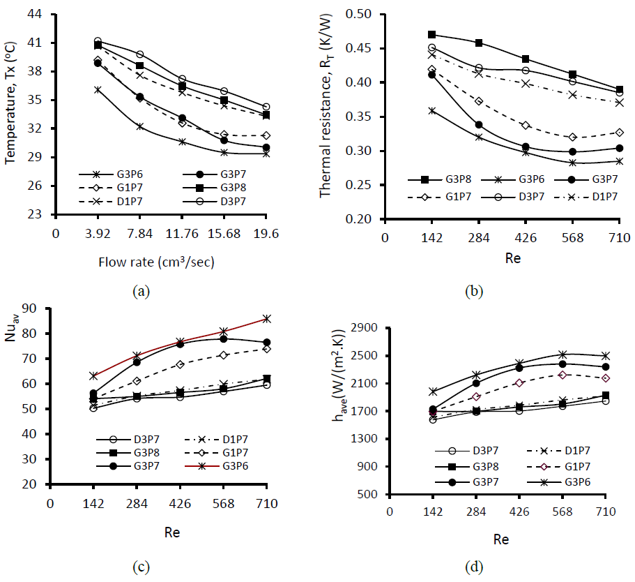
Figure 13 illustrates the thermal performance comparison of various Gyroid and Diamond structures, based on different parameters as a function of flow. Figure 13a compares measured surface temperatures. The Gyroid structure G3P6 (with a 12.5 mm cell size and 60% porosity) exhibits the lowest surface temperature among all structures. In comparison, the Diamond structure (with 12.5 mm cell size and 70% porosity) has the highest surface temperature. This indicates that the Gyroid structure G3P6 has the highest heat dissipation capacity, whereas the Diamond structure D3P7 has the lowest. When comparing Gyroid structures with the same cell size (G3P6, G3P7, and G3P8) but varying porosities (60%, 70%, and 80%, respectively), it is evident that the structure with the lowest porosity (G3P6) maintains the lowest surface temperature, while the opposite is true for the highest porosity. Increasing the cell size to 15 mm (G1P7) results in a surface temperature nearly equivalent to that of G3P7. Furthermore, a comparison between Gyroid and Diamond structures with the same cell size and porosity (G1P7 and D1P7) reveals that the Gyroid structure has a lower surface temperature than its Diamond counterpart. Moreover, the surface temperature of each structure decreases with increasing flow rates. These results suggest that the surface temperature of the investigated structures is significantly influenced by both the flow rate and their geometric characteristics.
To assess the heat transfer performance of the investigated structures, the Nusselt number and convection heat transfer coefficient were analyzed, as they are direct indicators of heat transfer efficiency. Variations in these parameters with flow rate are illustrated in Figure 13c and Figure 13d, respectively. Among the Gyroid structures with identical cell sizes (G3P6, G3P7, G3P8), the G3P6 configuration, which has a cell size of 12.5 mm and a low porosity of 60%, exhibits the highest convection heat transfer coefficient and Nusselt number. This indicates that G3P6 is more effective at dissipating heat than other structures. The enhanced heat dissipation could be due to its larger surface area and high specific surface area, as detailed in Table 1. Conversely, the G3P8 structure, characterized by a higher porosity of 80%, shows the lowest thermal performance. This reduction can be attributed to its smaller geometric surface area, which reduces heat transfer compared to the other Gyroid configurations. Furthermore, when comparing the Gyroid and Diamond structures (both with base), the Gyroid structures show higher Nusselt numbers and convection heat transfer coefficients than their Diamond counterparts. This indicates adding the base to the Diamond sample restricts fluid flow and increases flow separation, thereby diminishing its efficiency in heat transfer.
Further analysis of the convection heat transfer coefficient and Nusselt number (as shown in Figure 8 and Figure 9) provides an interesting result. The relationship between these parameters and the Reynolds number for each Gyroid and Diamond structure is presented in Table 2. Specifically, the trends for the structures G3P6, G3P7, and G1P7 indicate that the Nusselt number and convection heat transfer coefficient initially increase with the Reynolds number, reaching a peak. After this peak, both the Nusselt number and the convection heat transfer coefficient decline as the Reynolds number continues to rise. This characteristic suggests the existence of an optimal flow rate at which heat transfer is maximized. Beyond this optimal point, a further increase in flow rate provides diminishing returns in heat transfer performance. As can be seen from Table 2, the R2 value for all six structures is above 0.987, indicating that the fitting value is highly reliable. This result is important for optimizing the design and operation of systems utilizing these structures such as electronic cooling. This indicates the importance of maintaining flow rates within a specific range to achieve optimal thermal performance of these structures.
Another important thermal parameter investigated is the overall thermal resistance. This parameter measures the resistance to heat transport through the material and is crucial for assessing the effectiveness of thermal management systems. The overall thermal resistance of the examined structures is affected by their complex geometry, the interconnected network of solid and void spaces, and the material properties of the structure. The Gyroid and Diamond structures with base are compared in terms of their overall thermal resistance as presented in Figure 13b. Comparison of Gyroid structures with the same cell size but varying porosities (G3P6, G3P7, and G3P8) shows that G3P8 (which has the highest porosity, 80%) exhibits the greatest overall thermal resistance. In comparison, G3P6 (G3P6 with 60% porosity) showed the lowest thermal resistance, resulting in improved heat transfer performance. This improvement can be attributed to the greater surface area of the low-porosity Gyroid samples, which allows for more efficient heat dissipation. These results further validate the thermal performance indicated by the Nusselt number and convection heat transfer coefficient. In addition, except for G3P8, the Diamond structures (D3P7 and D1P7) exhibit lower thermal resistance than the other Gyroid structures. This suggests that the inclusion of the base has raised the thermal resistance of the Diamond structures more significantly than that of the Gyroid structures.
The trend for the overall thermal resistance of the investigated structures was also determined, as summarized in Table 2. An interesting characteristic trend in overall thermal resistance is obtained for the Gyroid structures (G3P6, G3P7, and G1P7). As depicted in Figure 13b, the data indicate that the thermal resistance for these structures initially decreases as the Reynolds number increases, reaching a minimum value. Beyond this point, a further increase in flow rate (Reynolds number) raises thermal resistance. This indicates the presence of an optimal flow rate that minimizes the overall thermal resistance. Exceeding this optimal flow rate leads to a declining return in heat transfer performance.
The thermophysical properties of distilled water were obtained from the COMSOL Multiphysics Material Library at the operating temperature, whereas the thermal conductivity of the AlSi10Mg alloy was taken from our previous work [38].
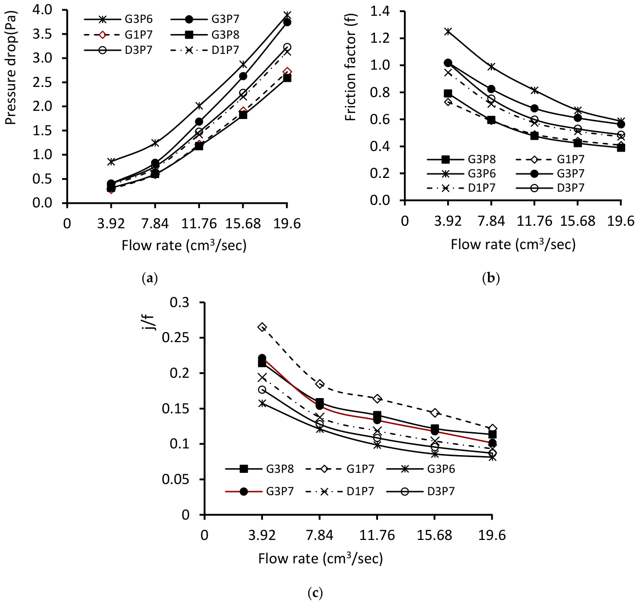
As previously stated in the literature review, the TPMS structures have recently attracted considerable interest in various application areas, especially in thermal management such as electronic cooling or heat sinks and heat exchangers. In such applications, it is important to characterize and analyze their hydraulic performance. This parameter directly determines the pumping power requirements and overall system performance. Consequently, the hydraulic performance of each investigated structure was assessed in terms of pressure drop and friction factors as a function of volume flow rate. The pressure drop between the inlet and outlet was numerically calculated using COMSOL Multiphysics for each Gyroid and Diamond structure. A comparison of pressure drop and friction factor for each structure is illustrated in Figure 14a and Figure 14b, respectively. When comparing Gyroid structures with the same cell size of 12.5 mm but varying porosities (G3P6, G3P7, G3P8), it was observed that G3P6, characterized by low porosity (60%), exhibited the highest pressure drop and friction factor. In contrast, G3P8, which has a higher porosity, showed the lowest pressure drop and fluid resistance. Additionally, it is evident that G1P7, which features a larger cell size, exhibits a lower pressure drop and friction factor compared to the Gyroid structures G3P6 and G3P7. Moreover, G1P7 demonstrates nearly identical pressure drop and friction factor values to those of G3P8. Furthermore, a comparison of Gyroid and Diamond structures, both with a porosity of 70% and larger cell sizes (G1P7 and D1P7), showed that the Diamond structure (D1P7) has a greater pressure loss and friction factor. In contrast, when examining G3P7 and D3P7 (both with the same porosity and smaller cell sizes), it was found that the Gyroid structure (G3P7) exhibited a higher pressure loss and friction factor than its Diamond counterpart, D3P7. Thus, the structures with larger cell sizes (G1P7 and D1P7), despite having lower surface areas (6580.6 mm2 and 7262.8 mm2, respectively), demonstrate reduced pressure loss and friction factors compared to the structures with smaller cell sizes (G3P7 and D3P7), which have surface areas of 7362.1 mm2 and 7915 mm2. This shows that structures with small cell sizes have more flow resistance than those with larger ones. The results from the pressure drop indicate a complex relationship between cell size, porosity, and fluid dynamics in the TPMS structures.
Finally, to evaluate and compare the overall thermal–hydraulic performance of different investigated Gyroid and Diamond structures, the ratio of the Colburn factor to friction factor (j/f) is used. A comparison of the overall performance parameter for all six structures is presented in Figure 14c in terms of the j/f value as a function of volume flow rate. Based on this parameter, the Gyroid structure with a larger cell size (G1P7) achieved the highest value keeping the balance between thermal performance and hydraulic performance while the lowest value was achieved by the Gyroid structure with a smaller cell size and low porosity (G3P6). Comparison of Gyroid structure with Diamond structure shows that the Diamond structures showed a lower j/f than that of the Gyroid structure. Furthermore, Figure 14c illustrates that the j/f value decreases with increasing volume flow rate across all structures. The trends indicate that further increases in flow rate do not enhance thermal performance. This observation is also evident in the j/f trends for each structure, as shown in Table 2, which are expressed in terms of Reynolds number. This suggests that beyond a certain flow rate, there are no additional benefits to overall performance. The identified trend of overall performance in terms of flow rate offers a valuable estimation for the performance characteristics of TPMS-based Gyroid and Diamond structures, eliminating the need for complex differential equation solutions.

4. Numerical Simulation Results and Discussion

This section presents numerical analysis of the thermal performance of six TPMS structures previously experimentally investigated: Gyroid and Diamond structures. COMSOL Multiphysics software is applied to simulate the flow and temperature distribution within each structure.
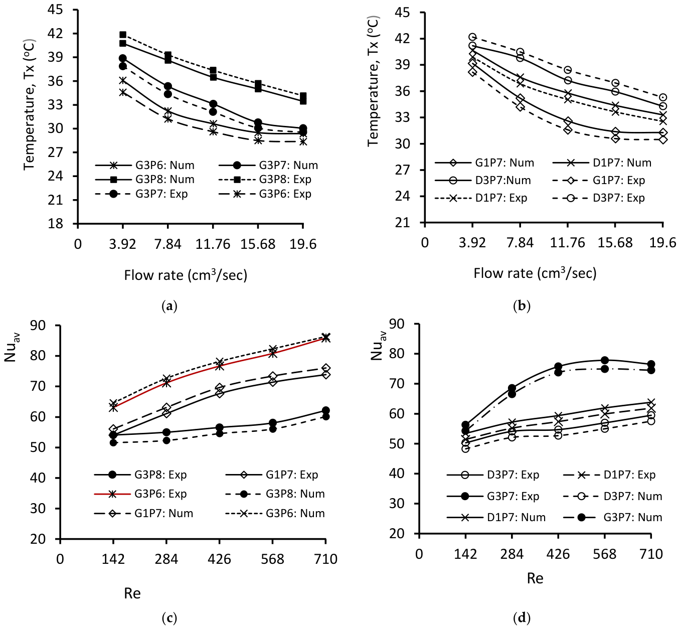
To validate the numerical model, the predicted surface temperatures, Nusselt numbers, and pressure drops were compared with the corresponding experimental measurements over the investigated flow-rate range. The same operating conditions and experimentally measured input parameters were used in the numerical simulations. Comparative analyses were done to check whether the model could accurately predict both the temperature response and the convective heat-transfer performance of the TPMS structures. Figure 15 presents the comparison between the numerical predictions and experimental measurements for all investigated structures. As shown in Figure 15a,b, the predicted temperatures agreed closely with the experimental data, with a maximum relative difference of only 4.3%. Similarly, the comparison of the Nusselt numbers presented in Figure 15c,d showed a maximum difference of 4.8%. Moreover, the numerically predicted temperature and Nusselt number followed the experimentally observed trends over the entire investigated flow-rate range.
Furthermore, to show the agreement between the numerical predictions and experimental measurements, we utilized root-mean-square error (RMSE). The agreement between the numerical predictions and experimental measurements was quantified using the root-mean-square error (RMSE). For each investigated TPMS configuration, the RMSE was calculated from the measured and predicted surface temperatures over the investigated flow-rate range. The calculated RMSE for the temperature (presented in Figure 15a, and Figure 15b) is G3P6, G3P7, G3P8, G1P7, D1P7 and D3P7 are 1.09 °C, 0.90 °C, 0.86 °C, 0.88 °C, 0.78 °C and 1.01 °C, respectively. The RMSE values are close to or below 1 °C. This shows that the numerical model predicts the surface temperatures with a typical error of approximately 0.8 to 1.1 °C. This suggests good and consistent agreement across all six TPMS configurations. The RMSE of the Nusselt number for each structure (G3P6, G3P7, G3P8, G1P7, D1P7, and D3P7) is 1.26, 2.24, 2.1, 2.2, 1.95, and 2.1, respectively. These relatively low errors, compared with the magnitude of the measured Nusselt numbers, indicate that the numerical model accurately captured the convective heat-transfer response and its variation with the Reynolds number.
From the above results, good agreement was observed between the numerical and experimental results for all TPMS configurations. This confirms that the applied numerical model accurately predicted the coupled heat transfer and fluid flow behavior within the investigated structures. The difference between the two approaches is attributed to experimental measurement uncertainties, dimensional and surface deviations introduced during additive manufacturing, and simplifying numerical assumptions (including constant thermophysical properties and hydraulically smooth walls).
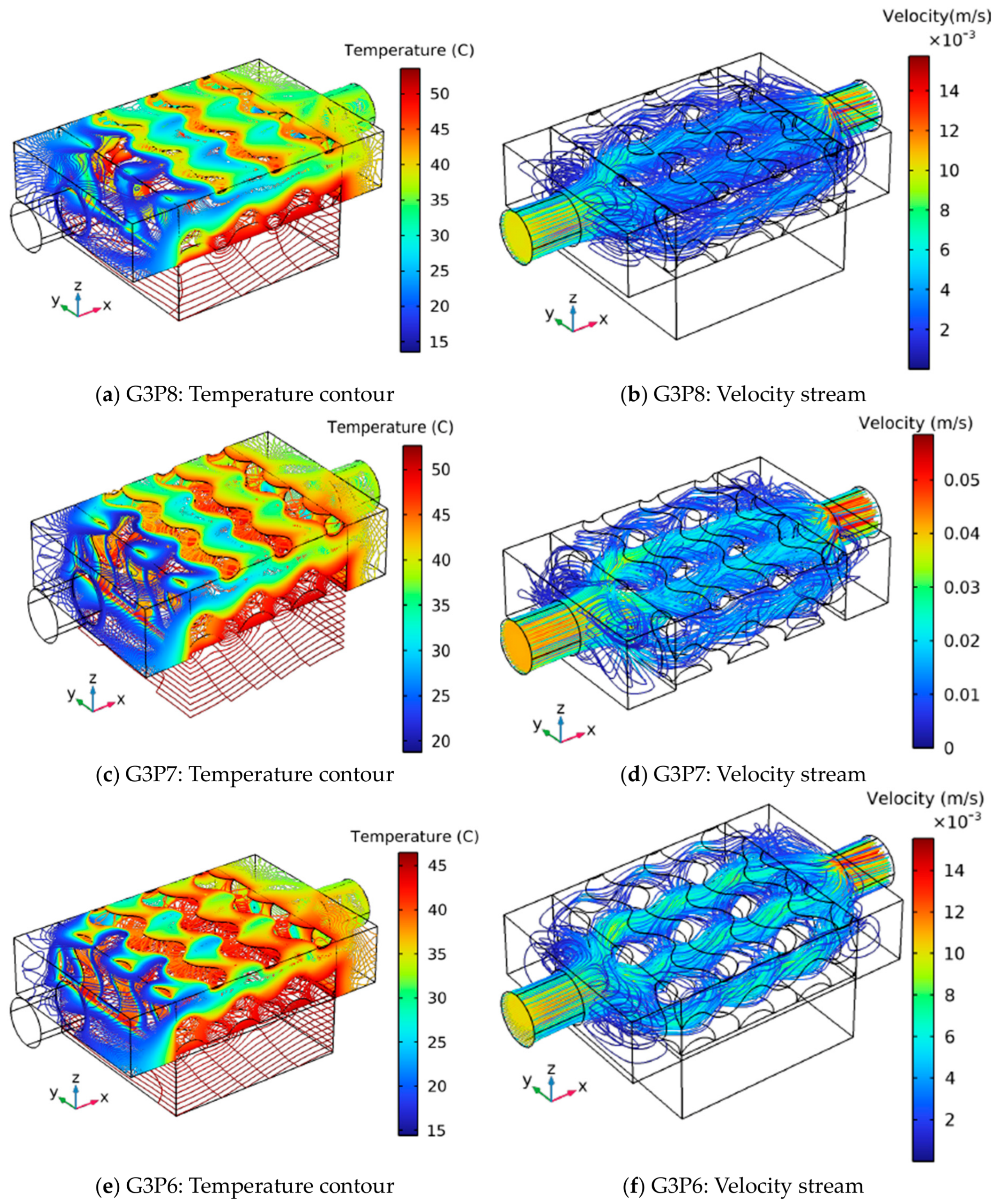
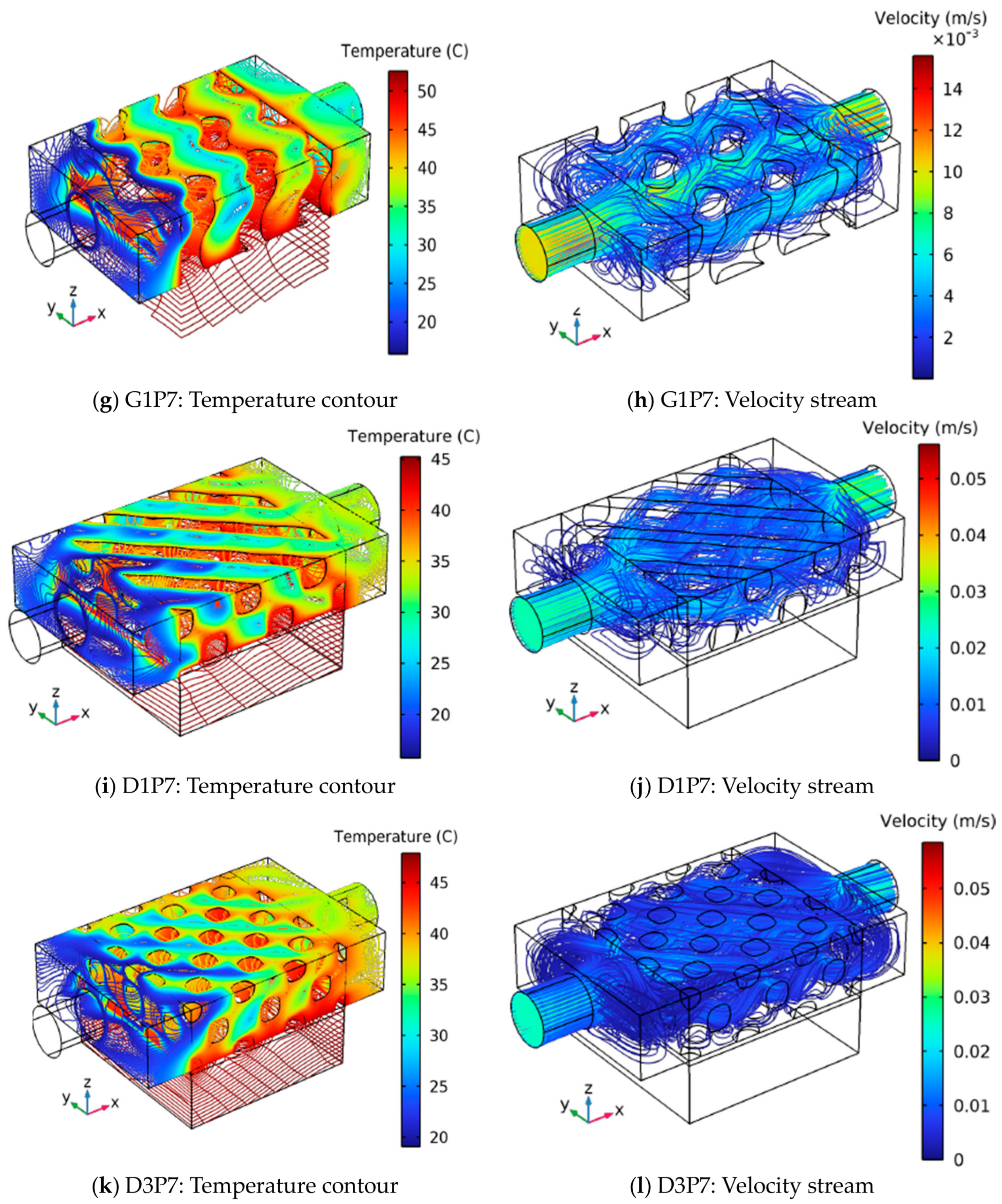
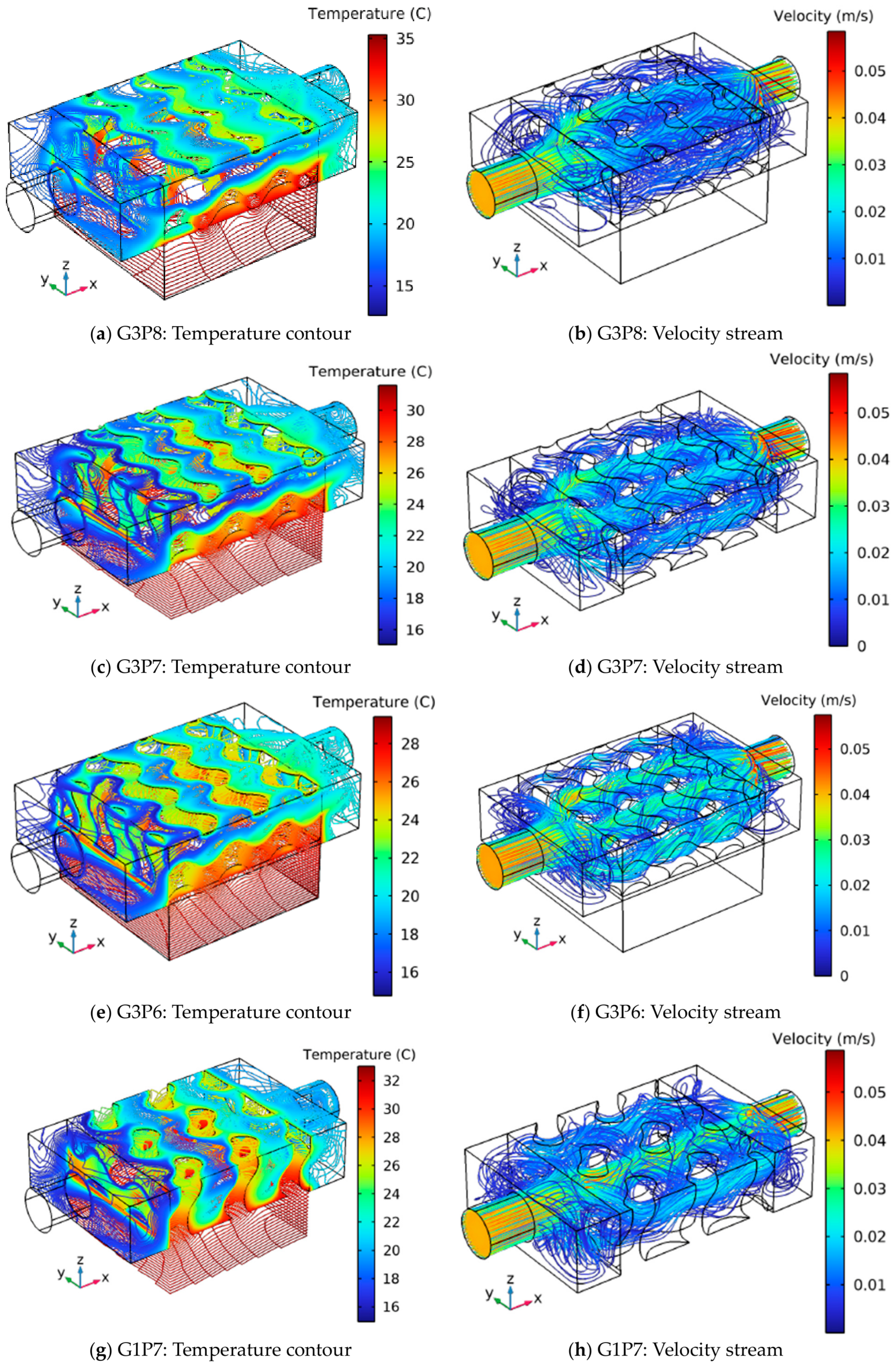
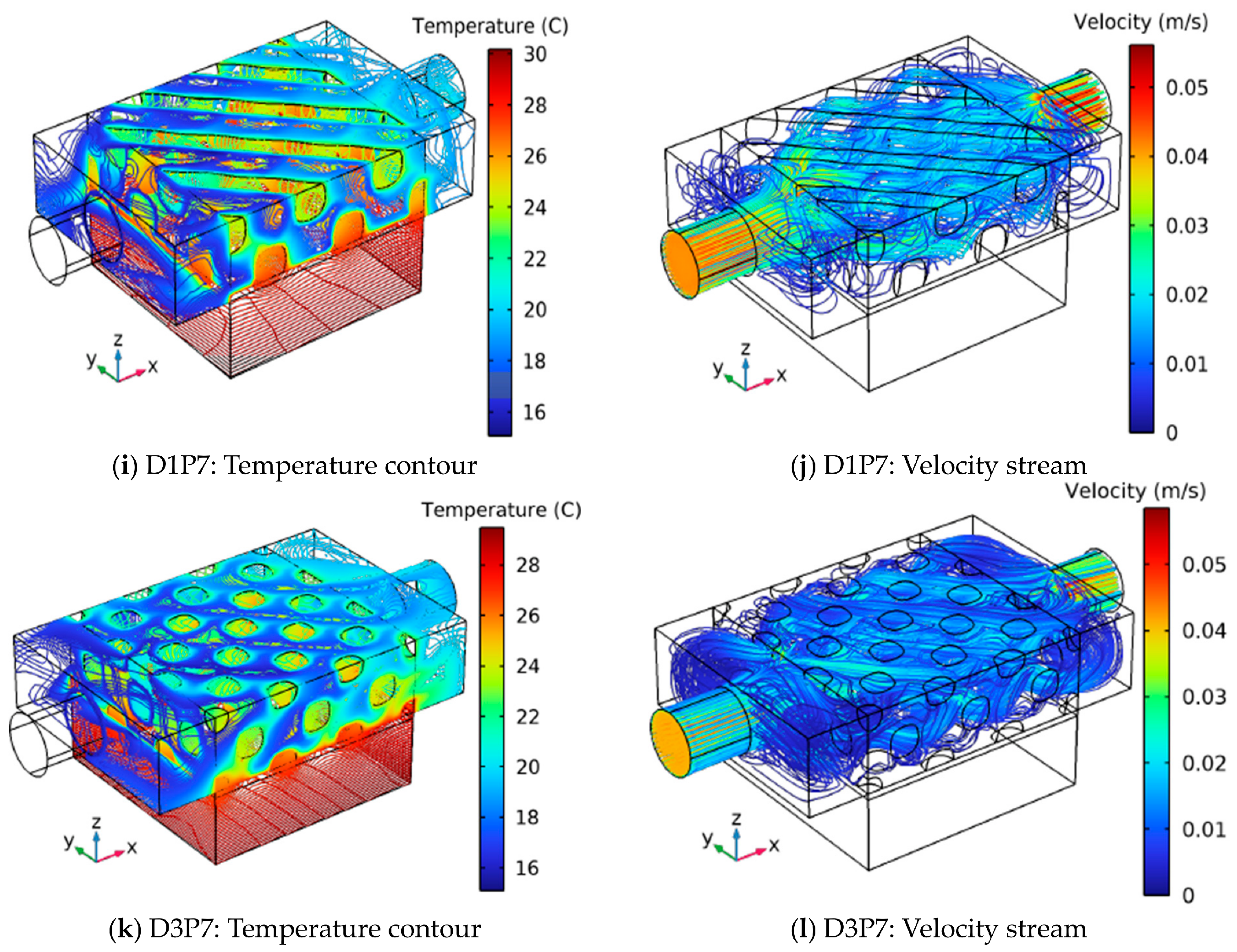
To ensure consistency, all six structures were analyzed under the same boundary conditions presented in Section 2. As previously mentioned, a constant heat flux of 3.86 W/cm2 (corresponding to a heat transfer rate of 54.3 W) is supplied at the bottom of each structure. The numerical results, thus obtained, are illustrated in Figure 15 and Figure 16 in 3D in terms of the temperature contours and velocity streams for volume flow rates of 3.92 cm3/s (corresponding to 0.01 m/s) and 19.68 cm3/s (0.041 m/s) at an inlet working fluid temperature of 16 °C.
Figure 16 and Figure 17 show the temperature contours and velocity stream of the six structures investigated. From the results depicted in Figure 16 and Figure 17, we can identify areas of high and low temperatures using temperature contours, indicating how heat is transferred through the structure. There is surface temperature fluctuation (in 3D directions) along the length and height of each structure.
In both Gyroid (G3P8, G3P7, G3P6, G1P7) and Diamond structures (D1P7 and D3P7), Figure 16 and Figure 17 illustrate different high-temperature and low-temperature regions. The high-temperature regions, depicted in red on the temperature contours, are primarily located near the bottom surface of each structure where heat flux is applied. These areas represent regions where heat is absorbed from the heat source. Conversely, the low-temperature regions are found at the inlet and further away from the heat source. This region represents areas where heat is effectively transferred to the cooling water. Additionally, the simulation results include velocity streams corresponding to the temperature contours for each structure, as shown in Figure 16 and Figure 17. As the water flows through each Gyroid and Diamond structure, the velocity varies across the length of each structure due to the fluid spreading through the structure. The results reveal that the low-temperature areas align with high-velocity regions, indicating intense fluid flow near the inlets of each structure. The high velocities assist with significant heat transfer to the water by convection, removing heat and leading to a lower surface temperature. In contrast, the low-velocity region (represented in blue in Figure 16 and Figure 17) indicates areas of reduced heat dissipation. The complex geometry of the investigated structures created such regions of varying flow resistance, leading to high- and low-velocity areas. The velocity is highest near the inlet where the fluid enters each structure and decreases as the fluid moves through the structure and exits. Furthermore, the complex geometry of the Gyroid or Diamond structure hinders fluid flow, resulting in lower convection rates and consequently higher surface temperatures.
It can also be seen from the generated results that Diamond structures (D1P7 and D3P7) enable a more uniform flow distribution within the opening pores, which enhances the interaction between the heating surface and the incoming flow. However, this uniformity comes at a cost, as the Diamond structures also present more resistance to flow. In contrast, the Gyroid structures exhibit lower flow resistance, resulting in a less dispersed flow pattern. This characteristic of Gyroid structures allows for higher temperatures compared to Diamond structures.
The analysis of the temperature contours of the six TPMS structures, as illustrated in Figure 16 and Figure 17, provides important findings about their thermal performance under varying flow conditions. Specifically, the gyroid structure G3P8, characterized by the highest porosity, exhibited the highest variations in temperature distribution. At an inlet temperature of 16 °C and a low inlet fluid flow rate of 3.92 cm3/s (0.01 m/s), the average temperature within the structure was 44.2 °C, with peak hotspot temperatures reaching up to 52 °C. Conversely, at a higher flow rate of 19.63 cm3/s (0.041 m/s), while maintaining the same inlet fluid temperature (16 °C), the thermal response of G3P8 improved significantly. At this flow rate, the average temperature dropped to 33.6 °C, while the maximum temperature reached only 27.2 °C. The increased fluid flow enhanced convective heat transfer, resulting in better cooling efficiency and more uniform temperature distribution across the structure.
Among the six structures analyzed, the G3P6 structure showed the highest thermal performance, achieving the lowest maximum and average temperatures under identical boundary conditions. At an inlet temperature of 16 °C and a low inlet fluid flow rate of 3.92 cm3/s (0.01 m/s), G3P6 achieved an average temperature of 35.7 °C and a maximum temperature of 44.1 °C. When subjected to a high inlet fluid flow rate of 19.63 cm3/s (0.041 m/s) while maintaining the same inlet temperature (16 °C), the structure demonstrated further enhancement in thermal dissipation. Under these conditions, the average temperature dropped to 29.5 °C, while the maximum temperature was reduced to 23.4 °C, indicating efficient heat transfer and lower thermal resistance.
The comparative analysis of the surface temperature of the investigated structures at inlet temperatures 16 °C and 12 °C is summarized in Table 3, and Table 4, respectively 6. These results emphasize the thermal efficiency of each TPMS structure under various operating conditions. Comparison of temperature contours, velocity streamlines, and analysis of the average surface temperature across different structures indicates that G3P6 exhibits the highest thermal performance, showing the highest heat dissipation and lower temperature gradients. In contrast, G3P8, despite its higher porosity, showed the lowest thermal performance (lowest heat dissipation efficiency) under the given boundary conditions. This finding implies that while high porosity structures like G3P8 may enhance fluid movement, they may not necessarily improve heat transfer due to increased thermal resistance (as indicated in the previous result) and localized heating effects. This confirms that the thermal performance of TPMS structures is highly dependent on their geometric characteristics, fluid flow rate, and inlet flow conditions.
Table 3. Surface temperature analysis for different structures at 16 °C inlet temperature, with low (3.92 cm3/s) and high (19.63 cm3/s) flow rates.


TPMS Structure: Maximum
Maximum, Average, and Minimum Surface Temperature at Low (3.92 cm3/s) and High (19.63 cm3/s) Flow Rates, and
16 °C Inlet Temperature
Tmaximum (°C)Taverage (°C)Tminimum (°C)
G3P8 52 (33.6)44.2 (27.2)31.5 (18.3)
G3P747.2 (29.9)39.3 (24.9)34.8 (19.9)
G3P644.1 (29.5)35.7 (23.4)14.7 (15.1)
G1P752.7 (33.1)41.8 (25.9)15.7 (14.9)
D1P745.3 (30.2)36.9 (24)15.6 (15)
D3P746.6 (29.5)38.3 (23.9)14.3 (14.7)
Table 4. Surface temperature analysis for different structures at 12 °C inlet temperature, with low (3.92 cm3/s) and high (19.63 cm3/s) flow rates.
TPMS StructureMaximum, Average, and Minimum Surface Temperature at Low (3.92 cm3/s) and High (19.63 cm3/s) Flow Rates, and
12 °C Inlet Temperature
Tmaximum (°C)Taverage (°C)Tminimum (°C)
G3P848.1 (29.8)40.3 (23.3)27.7 (14.4)
G3P743.4 (26.1)35.4 (21)31 (16.1)
G3P640.2 (25.7)35.7 (19.5)10.3 (10.9)
G1P748.9 (29.3)37.9 (22)11.6 (10.8)
D1P741.5 (26.4)33 (20.1)11.7 (10.9)
D3P742.8 (25.6)34.5 (20)10.4 (10.7)
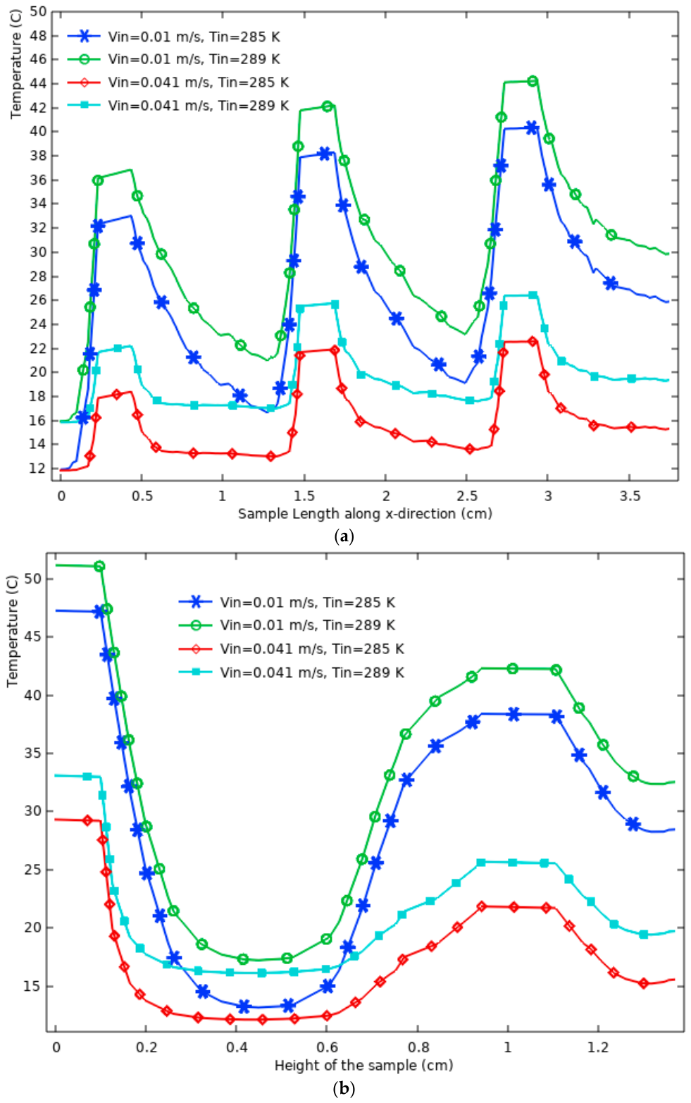
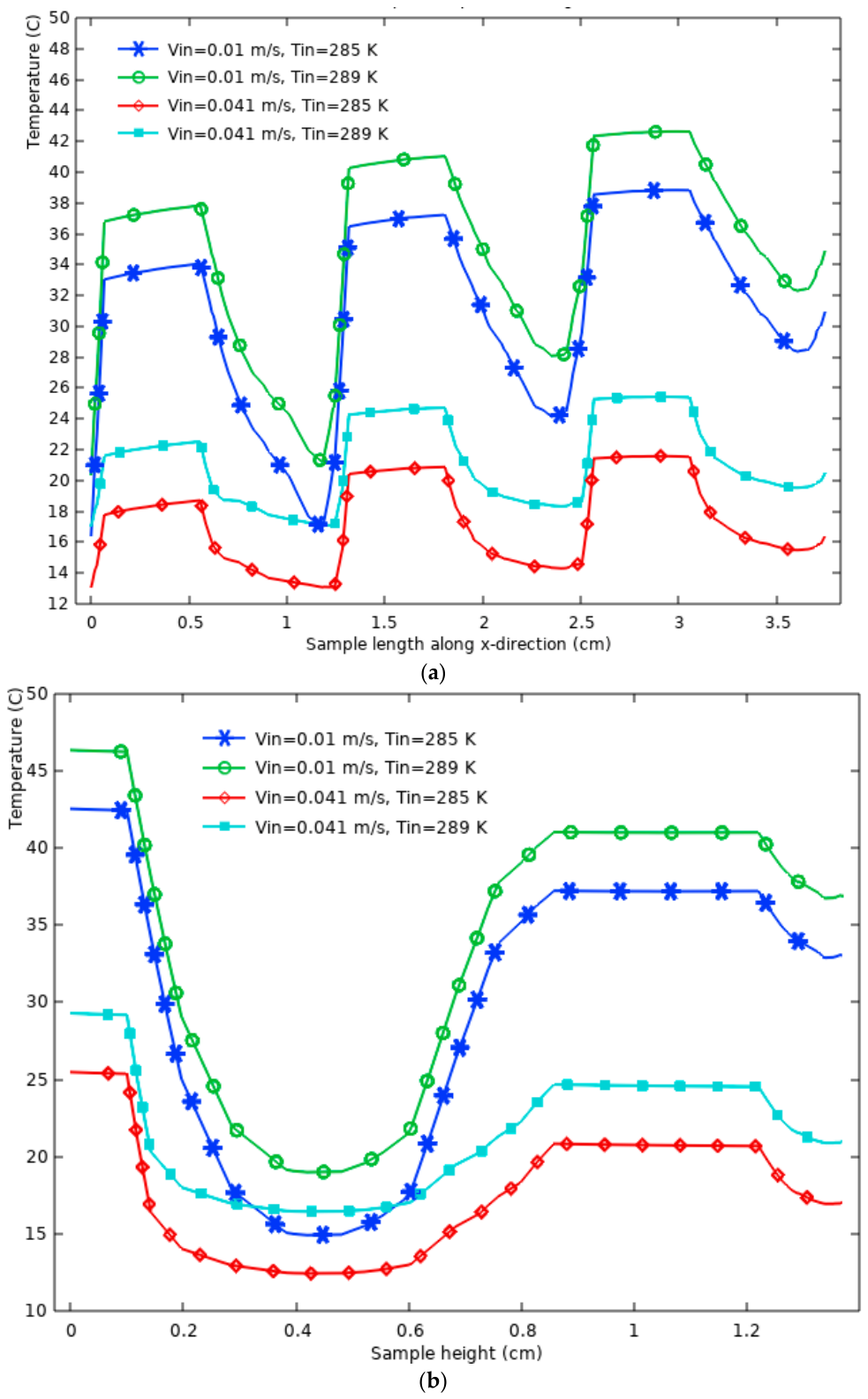
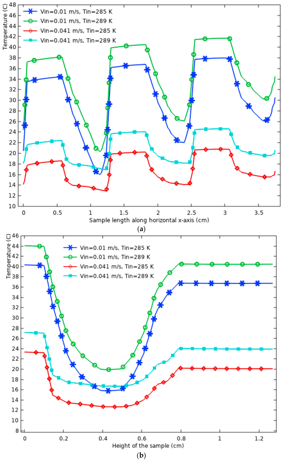
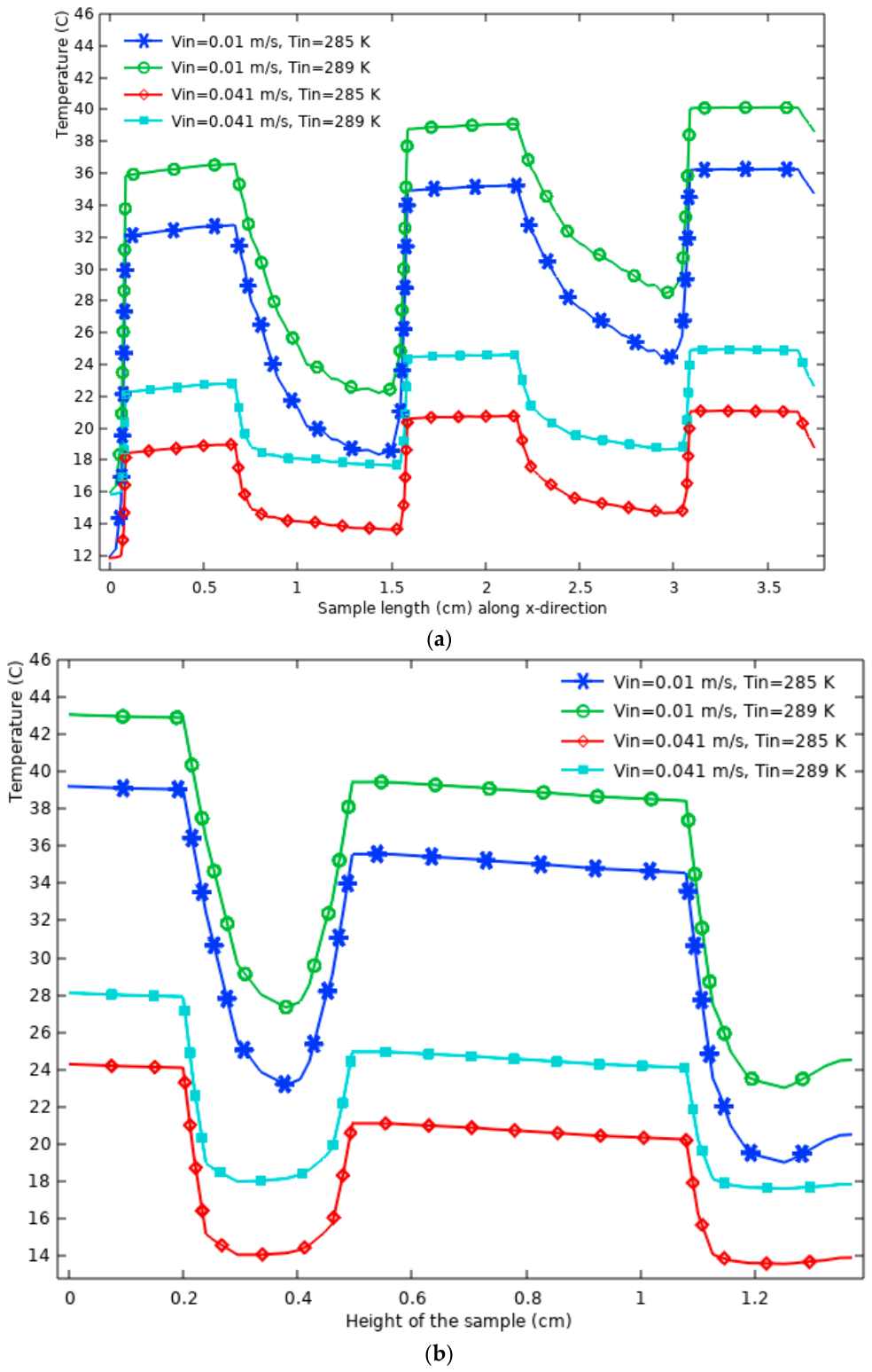
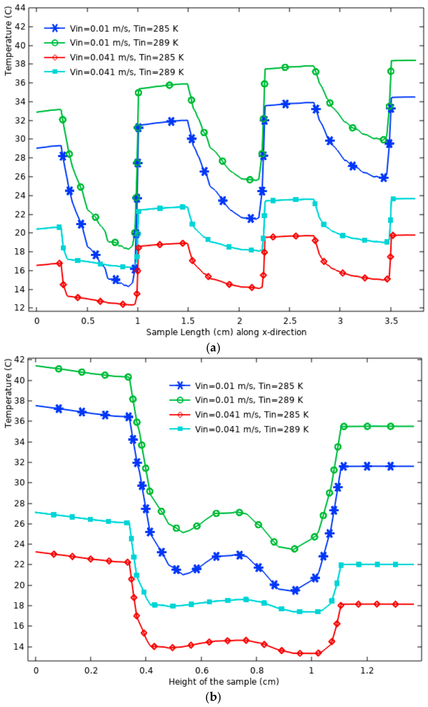
To further illustrate how each structure dissipates heat and maintains temperature distribution, the temperature variation along the middle horizontal line (x-axis) and a middle vertical line of the investigated structures is analyzed as shown in Figure 18, Figure 19, Figure 20, Figure 21 and Figure 22. The simulations were conducted for working fluid inlet temperatures of 12 °C (285 K) and 16 °C (289 K), along with low and high flow rates of water (3.92 cm3/s (0.01 m/s) and 19.63 cm3/s (0.041 m/s)). The results indicate that the temperature fluctuated along the length (x-direction), width (y-direction), and height (z-direction) of the examined TPMS structures. This fluctuation is influenced by the complex geometric design of each TPMS structure, which exhibits a periodically changing surface shape in the x, y, and z directions. That is, heat conduction through the structure and dissipation into the water creates recurring temperature variations that correlate with the repeating units of the Gyroid and Diamond structures. This behavior is consistent with Fourier’s Law, which governs heat conduction and emphasizes the significance of thermal resistance in the temperature distribution. Specifically, regions with higher thermal resistance lead to localized heat accumulation, while regions with lower thermal resistance enhance heat dissipation. As heat is supplied from the bottom surface, it transfers through the porous structure and encounters alternating regions of high and low thermal resistance, resulting in a wave-like temperature distribution along the length of the structure (Figure 18a, Figure 19a, Figure 20a, Figure 21a and Figure 22a). This temperature variation is attributed to the porous geometry of TPMSs, which creates alternating heat absorption and dissipation areas. The increased surface area-to-volume ratio of these Gyroid and Diamond structures facilitates localized heat transfer, a characteristic beneficial for applications such as heat sinks (in electronic cooling) and heat exchangers. Along the height (z-direction), the temperature profiles exhibit a similar pattern. The temperature peaks near the bottom, where heat is applied, decreases as heat dissipates into the water, and fluctuates within the porous structure before finally decreasing near the top (Figure 18b, Figure 19b, Figure 20b, Figure 21b and Figure 22b). These temperature variations are governed by the interaction between conduction through the solid material and convective heat transfer into the fluid.
Further analysis of results presented in Figure 18, Figure 19, Figure 20, Figure 21 and Figure 22 reveals the effect of inlet fluid velocity on temperature distribution. At a higher velocity (0.041 m/s), the temperature profile is more uniform, with less pronounced peaks and troughs compared to the lower velocity (0.01 m/s). This behavior is attributed to enhanced convective heat transfer, as governed by Newton’s Law of Cooling, where the heat transfer rate increases with higher fluid velocity. The increased velocity promotes better mixing and reduces the formation of localized high-temperature regions, thereby improving thermal performance.
The effect of inlet fluid temperature is also significant. As shown in Figure 18, Figure 19, Figure 20, Figure 21 and Figure 22, an inlet temperature of 289 K results in a higher overall surface temperature profile compared to 285 K. This outcome is expected, as the higher initial fluid temperature reduces the temperature gradient between the structure and the fluid, thereby reducing the heat transfer rate. Conversely, a lower inlet temperature (285 K) and higher inlet velocity (0.041 m/s) provide the lowest surface temperature and the highest heat dissipation. This indicates the importance of optimizing both inlet temperature and flow rate to achieve efficient heat transfer.
In conclusion, the results presented in Figure 18, Figure 19, Figure 20, Figure 21 and Figure 22 show that the temperature profile variations in TPMS structures are primarily driven by their geometric design, which creates alternating regions of thermal resistance. The interplay between the structure’s porosity, flow velocity, and inlet temperature significantly affects the heat dissipation characteristics. These results show the potential of TPMS structures for applications requiring efficient thermal management, such as in compact heat exchangers and heat sinks in electronic cooling systems.
Base-free TPMS structures are preferable when maximum heat transfer and low surface temperature are the main objectives, especially when sufficient external mechanical support is available. Typical examples include electronic cooling, compact heat sinks, and lightweight heat exchangers, where minimizing surface temperature and maximizing convective heat transfer are more important than additional structural rigidity. Removing the base increases the surface area exposed to the working fluid (coolant) and reduces the conduction path, which improves thermal performance. However, a base may still be necessary when structural strength, dimensional stability, sealing, mounting, or ease of installation are important. Its use therefore involves a trade-off between mechanical practicality and thermal–hydraulic performance. Another important design consideration is pumping power. Lower-porosity TPMS structures (such as G3P6) provide higher heat-transfer performance because of their larger specific surface area. However, they also generate higher pressure drops, resulting in high operating energy consumption. As a result, it is important to evaluate both thermal enhancement and pumping-power requirements when selecting a TPMS configuration for continuous operation. Manufacturing tolerances in wall thickness, roughness, and geometric accuracy may also influence local flow and heat transfer. In addition, thermal contact resistance between the heat source and the TPMS structure should be minimized using an appropriate thermal interface material. In the present experiments, thermal paste was used, and contact resistance was therefore assumed negligible in the numerical model. Finally, the results are mainly applicable to the investigated laminar-flow range, distilled water, and constant heat-flux conditions. Further work is needed to examine turbulent flow, other working fluids, wider heat-flux ranges, and long-term practical operation.

5. Conclusions

This study used experimental and numerical methods to investigate the heat transfer and fluid flow performance of six TPMS-based structures, specifically Gyroid and Diamond configurations. The impact of adding a base to these structures was analyzed in terms of surface temperature, convection heat transfer coefficient (Nusselt number), overall thermal resistance, pressure drop, friction factor, and overall thermal–hydraulic performance. The following conclusions were drawn:
  • In all six samples, the surface temperature of the structure with the base was higher than that without a base. The average surface temperature increase was 2.9 °C, 1.3 °C, 1.2 °C, 1.7 °C, 5.5 °C, and 4.5 °C for G3P8, G3P7, G3P6, G1P7, D3P7, and D1P7, respectively. This confirms that base-free structures dissipate more heat than structures with the base.
  • Adding the base reduces the convection heat transfer coefficient on average by 15.6%, 8.9%, 3.9%, 9.8%, 22.5%, and 23% for G3P8, G3P7, G3P6, G1P7, D3P7, and D1P7, respectively.
  • Adding the base increased overall thermal resistance by 22.7%, 10%, 3.1%, 9.1% for G3P8, G3P7, G3P6, and G1P7, respectively, while for Diamond structures (D3P7 and D1P7), the increases were 27.9% and 28.7%, respectively. Adding the base has resulted in Diamond structures experiencing more increase in thermal resistance compared to Gyroid structures.
  • The friction factor increased by 11.9% for G3P8, 18.4% for G3P7, 47.3% for G3P6, 7.3% for G1P7, 17.5% for D3P7, and 6.1% for D1P7 due to the addition of the base.
  • For all the samples, the overall thermal–hydraulic performance of the structure with the base is lower than that of the structure without the base. The performance reduction varies from 21.5% to 27.7% for G3P8, 2.4% to 16.6% for G3P7, 8.3 to 21.7% for G3P6, 12% to 21.8% for G1P7, 31.7% to 35.5% for D3P7 and 31.2% to 35.2% for D1P7.
  • The average overall thermal–hydraulic performance reductions due to the addition of the base were 23.9% for G3P8, 8.5% for G3P7, 15.3% for G3P6, 15.6% for G1P7, 33.6% for D3P7, and 33.5% for D1P7. With the addition of the base, the Diamond structures experience a more significant reduction in overall thermal–hydraulic performance than Gyroid structures.
  • The Gyroid structure G3P6 (with 12.5 mm cell size and 60% porosity) exhibits the lowest surface temperature among all structures. In comparison, the Diamond structure (with 12.5 mm cell size and 70% porosity) has the highest surface temperature.
  • Comparison of the Gyroid structures with the same cell size (G3P6, G3P7, and G3P8), but varying porosities, shows that the structure with the lowest porosity (G3P6) maintains the lowest surface temperature, while the opposite is true for the G3P8 with the highest porosity.
  • Among the Gyroid structures with the same cell size (G3P6, G3P7, G3P8), the G3P6 configuration (with the lowest porosity of 60%) exhibits the lowest surface temperature, highest convection heat transfer coefficient, and Nusselt number. This indicates that G3P6 is the most effective at dissipating heat than other structures.
  • The G3P8 structure, characterized by a higher porosity of 80%, shows the lowest thermal performance. Comparison between Gyroid and Diamond structures with the same cell size and porosity (G1P7 vs. D1P7) reveals that the Gyroid structure has a lower surface temperature than its Diamond counterpart.
  • Gyroid structures exhibited higher convection heat transfer coefficients and Nusselt numbers (higher heat dissipation capacity) than Diamond counterparts.
  • When comparing Gyroid structures with cell size of 12.5 mm and varying porosities (G3P6, G3P7, G3P8), the G3P6 characterized by low porosity (60%), exhibited the highest pressure drop and friction factor. In contrast, G3P8 (with the highest porosity, 80%) showed the lowest pressure drop and friction factor.
  • Based on the overall thermal–hydraulic performance parameter, the Gyroid structure with a larger cell size (G1P7) achieved the highest value keeping the balance between thermal performance and hydraulic performance while the lowest value was achieved by the Gyroid structure with a smaller cell size and low porosity (G3P6).

Author Contributions

Conceptualization, M.Z.S. and E.D.K.; methodology, M.Y.; software, M.Z.S.; validation, M.Z.S. and E.D.K.; formal analysis, M.Z.S.; investigation, E.D.K.; resources, M.Z.S.; data curation, E.D.K.; writing—original draft preparation, E.D.K.; writing—review and editing, M.Z.S., E.D.K. and M.Y.; funding acquisition, M.Z.S. All authors have read and agreed to the published version of the manuscript.

Funding

Natural Research Council of Canada RGPIN-2020-0721.

Data Availability Statement

The original contributions presented in this study are included in the article. Further inquiries can be directed to the corresponding Ziad Saghir.

Acknowledgments

The authors acknowledge the financial support of NSERC grant number RGPIN-2020-0721 and Toronto Metropolitan University.

Conflicts of Interest

The authors declare no conflicts of interest.

References

  1. Qian, C.; Wang, J.; Zhong, H.; Qiu, X.; Yu, B.; Shi, J.; Chen, J. Experimental investigation on heat transfer characteristics of copper heat exchangers based on triply periodic minimal surfaces (TPMS). Int. Commun. Heat Mass Transf. 2024, 152, 107292. [Google Scholar] [CrossRef] [Scilit]
  2. Li, W.; Li, W.; Yu, Z. Heat transfer enhancement of water-cooled triply periodic minimal surface heat exchangers. Appl. Therm. Eng. 2022, 217, 119198. [Google Scholar] [CrossRef] [Scilit]
  3. Li, W.; Yu, G.; Yu, Z. Bioinspired heat exchangers based on triply periodic minimal surfaces for supercritical CO2 cycles. Appl. Therm. Eng. 2020, 179, 115686. [Google Scholar] [CrossRef] [Scilit]
  4. Jung, Y.; Torquato, S. Fluid permeabilities of triply periodic minimal surfaces. Phys. Rev. E 2005, 72, 056319. [Google Scholar] [CrossRef] [Scilit] [PubMed]
  5. Yang, W.; An, J.; Chua, C.K.; Zhou, K. Acoustic absorptions of multifunctional polymeric cellular structures based on triply periodic minimal surfaces fabricated by stereolithography. Virtual Phys. Prototyp. 2020, 15, 242–249. [Google Scholar] [CrossRef] [Scilit]
  6. Ouda, M.; Al-Ketan, O.; Sreedhar, N.; Hasan Ali, M.I.; Abu Al-Rub, R.K.; Hong, S.; Arafat, H.A. Novel static mixers based on triply periodic minimal surface (TPMS) architectures. J. Environ. Chem. Eng. 2020, 8, 104289. [Google Scholar] [CrossRef] [Scilit]
  7. Dong, Z.; Zhao, X. Application of TPMS Structure in Bone Regeneration. Eng. Regen. 2021, 2, 154–162. [Google Scholar] [CrossRef] [Scilit]
  8. Mortazavi, A.; Ávila-Marín, A.L.; Ebadi, H.; Gajetti, E.; Piatti, C.; Marocco, L.; Savoldi, L. Experimental investigation of Triply Periodic Minimal Surfaces for high-temperature solar receivers. Case Stud. Therm. Eng. 2024, 60, 104771. [Google Scholar] [CrossRef] [Scilit]
  9. Kaur, I.; Singh, P. State-of-the-art in heat exchanger additive manufacturing. Int. J. Heat Mass Transf. 2021, 178, 121600. [Google Scholar] [CrossRef] [Scilit]
  10. Attarzadeh, R.; Rovira, M.; Duwig, C. Design analysis of the ‘Schwartz D’ based heat exchanger: A numerical study. Int. J. Heat Mass Transf. 2021, 177, 121415. [Google Scholar] [CrossRef] [Scilit]
  11. Attarzadeh, R.; Attarzadeh-Niaki, S.-H.; Duwig, C. Multi-objective optimization of TPMS-based heat exchangers for low-temperature waste heat recovery. Appl. Therm. Eng. 2022, 212, 118448. [Google Scholar] [CrossRef] [Scilit]
  12. Dixit, T.; Al-Hajri, E.; Paul, M.C.; Nithiarasu, P.; Kumar, S. High-performance, microarchitected, compact heat exchanger enabled by 3D printing. Appl. Therm. Eng. 2022, 210, 118339. [Google Scholar] [CrossRef] [Scilit]
  13. Chen, F.; Jiang, X.; Lu, C.; Wang, Y.; Wen, P.; Shen, Q. Heat transfer efficiency enhancement of gyroid heat exchanger based on multidimensional gradient structure design. Int. Commun. Heat Mass Transf. 2023, 149, 107127. [Google Scholar] [CrossRef] [Scilit]
  14. Yan, K.; Wang, J.; Li, L.; Deng, H. Numerical investigation into thermo-hydraulic characteristics and mixing performance of triply periodic minimal surface-structured heat exchangers. Appl. Therm. Eng. 2023, 230, 120748. [Google Scholar] [CrossRef] [Scilit]
  15. El Khadiri, I.; Abouelmajd, M.; Zemzami, M.; Hmina, N.; Lagache, M.; Belhouideg, S. Comprehensive analysis of flow and heat transfer performance in triply periodic minimal surface (TPMS) heat exchangers based on Fischer-Koch S, PMY, FRD, and Gyroid structures. Int. Commun. Heat Mass Transf. 2024, 156, 107617. [Google Scholar] [CrossRef] [Scilit]
  16. Al-Ketan, O.; Ali, M.; Khalil, M.; Rowshan, R.; Khan, K.A.; Abu Al-Rub, R.K. Forced Convection Computational Fluid Dynamics Analysis of Architected and Three-Dimensional Printable Heat Sinks Based on Triply Periodic Minimal Surfaces. J. Therm. Sci. Eng. Appl. 2020, 13, 021010. [Google Scholar] [CrossRef] [Scilit]
  17. Al-Ketan, O.; Abu Al-Rub, R.K. MSLattice: A free software for generating uniform and graded lattices based on triply periodic minimal surfaces. Mater. Des. Process. Commun. 2021, 3, e205. [Google Scholar]
  18. Du, X.; Wang, Z.; Gao, Q.; Yang, H.; Bao, R.; Xiong, S. Study on novel battery thermal management using triply periodic minimal surface porous structures liquid cooling channel. Appl. Therm. Eng. 2024, 257, 124384. [Google Scholar] [CrossRef] [Scilit]
  19. Xiong, S.; Wang, Z.; Bao, R.; Yang, H.; Zhang, B.; Du, X. Performance study and optimization of hybrid battery thermal management system based on triply periodic minimal surface coupled phase change material. J. Energy Storage 2024, 100, 113529. [Google Scholar] [CrossRef] [Scilit]
  20. You, H.; Lee, S.; Baek, C.; Han, C.; Kim, Y. Enhancement of heat transfer in cooling channels for electronic devices using multi-directional graded triply periodic minimal surfaces (TPMS). Int. Commun. Heat Mass Transf. 2024, 159, 108278. [Google Scholar] [CrossRef] [Scilit]
  21. Yeranee, K.; Rao, Y. A Review of Recent Investigations on Flow and Heat Transfer Enhancement in Cooling Channels Embedded with Triply Periodic Minimal Surfaces (TPMS). Energies 2022, 15, 8994. [Google Scholar] [CrossRef] [Scilit]
  22. Qureshi, Z.A.; Elnajjar, E.; Al-Ketan, O.; Al-Rub, R.A.; Al-Omari, S.B. Heat transfer performance of a finned metal foam-phase change material (FMF-PCM) system incorporating triply periodic minimal surfaces (TPMS). Int. J. Heat Mass Transf. 2021, 170, 121001. [Google Scholar] [CrossRef] [Scilit]
  23. Zhang, T.; Liu, F.; Deng, X.; Zhao, M.; Zhou, H.; Zhang, Z. Experimental study on the thermal storage performance of phase change materials embedded with additively manufactured triply periodic minimal surface architected lattices. Int. J. Heat Mass Transf. 2022, 199, 123452. [Google Scholar] [CrossRef] [Scilit]
  24. Gado, M.G. Improving the charging performance of latent heat thermal energy storage systems using triply periodic minimal surface (TPMS) structures. J. Energy Storage 2024, 103, 114310. [Google Scholar] [CrossRef] [Scilit]
  25. Cheng, Z.; Xu, R.; Jiang, P. Morphology, flow and heat transfer in triply periodic minimal surface based porous structures. Int. J. Heat Mass Transf. 2021, 170, 120902. [Google Scholar] [CrossRef] [Scilit]
  26. Tang, W.; Zhou, H.; Zeng, Y.; Yan, M.; Jiang, C.; Yang, P.; Li, Q.; Li, Z.; Fu, J.; Huang, Y.; et al. Analysis on the convective heat transfer process and performance evaluation of Triply Periodic Minimal Surface (TPMS) based on Diamond, Gyroid and Iwp. Int. J. Heat Mass Transf. 2023, 201, 123642. [Google Scholar] [CrossRef] [Scilit]
  27. Lesmana, L.A.; Aziz, M. Adoption of triply periodic minimal surface structure for effective metal hydride-based hydrogen storage. Energy 2023, 262, 125399. [Google Scholar] [CrossRef] [Scilit]
  28. Min, R.; Wang, Z.; Yang, H.; Bao, R.; Zhang, N. Heat transfer characterization of waste heat recovery heat exchanger based on flexible hybrid triply periodic minimal surfaces (TPMS). Int. Commun. Heat Mass Transf. 2024, 157, 107760. [Google Scholar] [CrossRef] [Scilit]
  29. Iyer, J.; Moore, T.; Nguyen, D.; Roy, P.; Stolaroff, J. Heat transfer and pressure drop characteristics of heat exchangers based on triply periodic minimal and periodic nodal surfaces. Appl. Therm. Eng. 2022, 209, 118192. [Google Scholar] [CrossRef] [Scilit]
  30. Baobaid, N.; Ali, M.I.; Khan, K.A.; Abu Al-Rub, R.K. Fluid flow and heat transfer of porous TPMS architected heat sinks in free convection environment. Case Stud. Therm. Eng. 2022, 33, 101944. [Google Scholar] [CrossRef] [Scilit]
  31. Gado, M.G. Thermal management and heat transfer enhancement of electronic devices using integrative phase change material (PCM) and triply periodic minimal surface (TPMS) heat sinks. Appl. Therm. Eng. 2025, 258, 124504. [Google Scholar] [CrossRef] [Scilit]
  32. Zhang, Y.; Peng, F.; Jia, H.; Zhao, Z.; Wang, P.; Duan, S.; Lei, H. Conformal geometric design and additive manufacturing for special-shaped TPMS heat exchangers. Int. J. Heat Mass Transf. 2025, 247, 127146. [Google Scholar] [CrossRef] [Scilit]
  33. Dharmalingam, L.; O’Malley, B.; Tancabel, J.; Aute, V. Design, optimization, and validation of a triply periodic minimal surface based heat exchanger for extreme temperature applications. Int. J. Heat Mass Transf. 2025, 242, 126797. [Google Scholar] [CrossRef] [Scilit]
  34. Reynolds, B.; Lecarpentier, F.; Holland, D. Heat transfer and topological characterisation of TPMS structures using 3D printed materials. Int. J. Heat Mass Transf. 2025, 245, 126992. [Google Scholar] [CrossRef] [Scilit]
  35. Yu, X.; Moreira, T.A.; Chen, B.; Rankouhi, B.; Thoma, D.J.; Anderson, M.H.; Qian, X. Data-driven optimization, additive manufacturing and thermohydraulic testing of a high-temperature Gyroid-based TPMS heat exchanger. Appl. Therm. Eng. 2025, 280, 128422. [Google Scholar] [CrossRef] [Scilit]
  36. Yanagihara, K.; Iwasaki, J.; Saso, K.; Yamashita, T.; Murakoshi, S.; Takezawa, A. Flow-priority optimization of additively manufactured variable-TPMS lattice heat exchanger based on macroscopic analysis. Addit. Manuf. 2026, 125, 105246. [Google Scholar] [CrossRef] [Scilit]
  37. Zhang, X.; Zou, Z.; Liu, J.; Zhang, Y.; Liang, Y.; Sun, Y.; Hao, M.; Zhong, W. Thermal-hydraulic performance of flat-tube air-to-fluid heat exchangers for vehicle applications using TPMS-based fins at varying altitudes. Int. J. Heat Mass Transf. 2026, 260, 128469. [Google Scholar] [CrossRef] [Scilit]
  38. Kerme, E.D.; Hajialibabei, M.; Ziad Saghir, M.; El-Ketan, O. Experimental investigation of porous gyroid structure: Effect of cell size and porosity on performance. Therm. Sci. Eng. Prog. 2024, 53, 102728. [Google Scholar] [CrossRef] [Scilit]
  39. Saghir, M.Z.; Hajialibabaei, M.; Al-Ketan, O. Optimization of the TPMS Heat Exchanger Toward Cooling the Heat Sink. Processes 2025, 13, 1786. [Google Scholar] [CrossRef] [Scilit]
Figure 1. Details of the experimental setup: (a) apparatus photo and (b) schematic diagram.
Processes 14 02672 g001
Figure 5. The variation of percentage error in temperature and pressure drop with the number of elements for G1P7 and D3P7.
Processes 14 02672 g005
Figure 6. (a) Different mesh levels generated for Gyroid structure (G1P7). (b) Different mesh levels generated for Diamond structure (D3P7).
Processes 14 02672 g006
Figure 7. Comparison of the surface temperature of different Gyroid and Diamond structures with base and without base.
Processes 14 02672 g007
Figure 8. Comparison of convection heat transfer coefficient of different Gyroid and Diamond structures with base and without base.
Processes 14 02672 g008
Figure 9. Comparison of Nusselt number of different Gyroid and Diamond structures with base and without base.
Processes 14 02672 g009
Figure 10. Comparison of the overall thermal resistance of different Gyroid and Diamond structures with base and without base.
Processes 14 02672 g010
Figure 11. Comparison of the friction factor (with base and without base) for the investigated TPMS structures.
Processes 14 02672 g011
Figure 12. Comparison of the overall performance of different TPMS structures with and without base.
Processes 14 02672 g012
Figure 13. Comparison of thermal performance of various Gyroid and Diamond structures based on (a) surface temperature, (b) overall thermal resistance, (c) Nusselt number, and (d) convection heat transfer coefficient.
Processes 14 02672 g013
Figure 14. Comparison of different Gyroid and Diamond structures based on (a) pressure drop, (b) friction factor, and (c) overall thermal–hydraulic performance.
Processes 14 02672 g014
Figure 15. Validation of the computational numerical model by experimental data.
Processes 14 02672 g015
Figure 16. Temperature contour (a,c,e) and velocity stream (b,d,f) of Gyroid structures (G3P8, G3P7, and G3P6) at low flow rate (3.92 cm3/s) and 16 °C inlet temperature. Temperature contour (g,i,k) and velocity stream (h,j,l) of Gyroid (G1P7) and Diamond (D1P7 and D3P7) structures at low flow rate (3.92 cm3/s) and 16 °C inlet temperature.
Processes 14 02672 g016aProcesses 14 02672 g016b
Figure 17. Temperature contour (a,c,e) and velocity stream (b,d,f) of Gyroid structures (G3P8, G3P7, and G3P6) at high flow rate (19.63 cm3/s) and 16 °C inlet temperature. Temperature contour (g,i,k) and velocity stream (h,j,l) of Gyroid (G1P7) and Diamond (D1P7 and D3P7) structures at high flow rate (19.63 cm3/s) and 16 °C inlet temperature.
Processes 14 02672 g017aProcesses 14 02672 g017b
Figure 18. (a) Temperature variation along the middle horizontal line in G3P8. (b) Temperature variation along the middle vertical line of G3P8.
Processes 14 02672 g018
Figure 19. (a) Temperature variation along the middle horizontal line in G3P7. (b) Temperature variation along the middle vertical line of G3P7.
Processes 14 02672 g019
Figure 20. (a) Temperature variation along the middle horizontal line of G3P6. (b) Temperature variation along the middle vertical line in G3P6.
Processes 14 02672 g020
Figure 21. (a) Temperature variation along the middle horizontal line in D1P7. (b) Temperature variation along the middle vertical line in D1P7.
Processes 14 02672 g021
Figure 22. (a) Temperature variation along the middle horizontal line containing two points in D3P7. (b) Temperature variation along the middle vertical line of D3P7.
Processes 14 02672 g022
Table 1. Geometric characteristics of the investigated Gyroid and Diamond structures without base [17].
ParametersInvestigated TPMS Structures
GyroidDiamond
G3P6 G3P7G3P8G1P7D1P7D3P7
Porosity0.600.700.800.700.700.70
Unit Cell Size (mm)12.512.512.5151512.5
Sample dimensions:
Length (mm)37.537.537.537.537.537.5
Width (mm)37.537.537.537.537.537.5
Height (mm)12.712.712.712.712.712.7
Surface Area (mm2)6305.15656.94692.95004.15671.06292.8
Specific Surface Area (m−1)353316.7262.8280.2317.5352.3
Table 2. Trends of Nusselt number, convection heat transfer coefficient, and overall thermal resistance for different structures.
SamplesThe Fitting (Trend) for  h a v (W/m2K)The Fitting (Trend) for N u a v
G3P8 h a v =  8 × 10⁻⁴Re2 − 0.2792Re + 1719.6; R2 = 0.9872Nuav = 2 × 10⁻⁵Re2 − 5.3 × 10⁻³Re + 54.527; R2 = 0.9866
G3P7 h a v =  3.5 × 10⁻³Re2 + 4.0394Re + 1230.2; R2 = 0.9987Nuav = −1 × 10⁻⁴Re2 + 0.1322Re + 39.959; R2 = 0.9989
G3P6 h a v = −2 × 10⁻³Re2 + 2.6115Re + 1645.4; R2 = 0.9961Nuav = −3 × 10⁻⁵Re2 + 0.0612Re + 55.29;
R2 = 0.9962
G1P7 h a v = 2.1 × 10⁻³Re2 + 2.7046Re + 1340.3; R2 = 0.9886Nuav = −4 × 10⁻⁴Re2 + 0.0711Re + 44.687;
R2 = 0.999
D1P7hav = −3 × 10⁻⁴Re2 + 0.8029Re + 1509.4; R2 = 0.9965Nuav = −1 × 10⁻⁵Re2 + 0.028Re + 47.845;
R2 = 0.9968
D3P7hav = 3 × 10⁻⁶Re3 − 3.8 × 10⁻³Re2 + 1.8923Re + 1378.4; R2 = 0.987Nuav = 1 × 10⁻⁷Re3 − 0.0001Re2 + 0.0659Re
+ 43.408; R2 = 0.9879
Samples The Trends for Overall Thermal Resistance, RT (K/W)
G3P8
G3P6
G3P7
G1P7
D1P7
D3P7
RT = 2 × 10⁻⁵Re3 − 6 × 10⁻⁴Re2 + 0.002.5 × 10−4Re + 0.4692; R2 = 0.9993
RT = 1 × 10⁻⁴Re2 − 0.0144Re + 0.4089; R2 = 0.9989
RT = 8 × 10⁻⁴Re2 − 0.0262Re + 0.4985; R2 = 0.991
RT = 6 × 10⁻⁴Re2 − 0.0196Re+ 0.4886; R2 = 0.9976
RT = 1 × 10⁻⁴Re2 − 7.8 × 10⁻³ + 0.4681; R2 = 0.9953
RT = −4 × 10⁻⁵Re3 + 1.3 × 10⁻³Re2 − 0.0183Re + 0.5043; R2 = 0.9855
SamplesThe Trends for overall performance, j/f
G3P8
G3P6
G3P7
G1P7
D1P7
D3P7
j/f = 0.3643Re−0.394; R2 = 0.9969
j/f = 0.4148Re−0.466; R2 = 0.9948
j/f = 0.2835Re−0.425; R2 = 0.9954
j/f = 0.4928Re−0.458; R2 = 0.9909
j/f = 0.3545Re−0.448; R2 = 0.9977
j/f = 0.3195Re−0.438; R2 = 0.9993
Disclaimer/Publisher’s Note: The statements, opinions and data contained in all publications are solely those of the individual author(s) and contributor(s) and not of MDPI and/or the editor(s). MDPI and/or the editor(s) disclaim responsibility for any injury to people or property resulting from any ideas, methods, instructions or products referred to in the content.