Article

Load Characteristics of Mechanical Cutters When Cutting Different Coal and Rock Formations and Entropy Features of the Samples

1
School of Energy and Mining Engineering, China University of Mining and Technology (Beijing), Beijing 100083, China
2
Chinese Institute of Coal Science, Beijing 100013, China
3
China Coal Research Institute, Beijing 100013, China
4
School of Mechanical Engineering, Heilongjiang University of Science and Technology, Harbin 150022, China
5
CCRl (Beijing) Testing Technology Co., Ltd., Beijing 102606, China
*
Author to whom correspondence should be addressed.
Processes 2026, 14(16), 2651; https://doi.org/10.3390/pr14162651
Submission received: 7 July 2026 / Revised: 29 July 2026 / Accepted: 5 August 2026 / Published: 20 August 2026

Abstract

The load characteristics and dynamic behavior of shearer drums under complex geological conditions—particularly coal seams with gangue interlayers, roofs, and floors—remain insufficiently understood due to the lack of systematic comparative studies across varying cutting scenarios. In this study, a three-dimensional finite element model of drum cutting was established using SolidWorks and HyperMesh, and explicit dynamic simulations were performed with LS-DYNA to investigate the triaxial loads (cutting resistance, traction resistance, and lateral force) under five distinct operating conditions. Theoretical calculations of cutting resistance for pure coal cutting yielded 91 kN, while the simulation result was 87.0245 kN, with a relative error of 4.37%, validating the reliability of the numerical model. Results reveal that gangue position exerts a differential influence on load components: upper gangue maximizes traction resistance (mean: 43.01 kN), whereas lower gangue leads to the highest cutting resistance (mean: 38.45 kN). Floor cutting, with the highest uniaxial compressive strength (75 MPa), produces the most severe load fluctuations. To further characterize the nonlinear dynamics, Ensemble Empirical Mode Decomposition (EEMD) coupled with sample entropy analysis was applied to the load signals. The high-frequency intrinsic mode functions (IMF1–2) of the floor-cutting traction resistance exhibited the highest sample entropy values, indicating pronounced impact characteristics and complex non-stationary behavior. These findings provide a quantitative basis for distinguishing cutting media (coal, gangue, roof, floor) and offer actionable insights for drum structural optimization and adaptive cutting control in intelligent mining operations.

1. Introduction

The drum of a shearer is the core actuating component for coal fragmentation and loading in fully mechanized mining faces. During operation, it is subjected to complex, time-varying loads combining impact, torsion, and bending, which directly govern the machine’s reliability, cutting efficiency, and service life. As coal mining progressively extends into deeper and more structurally complex seams—characterized by gangue interlayers, thin coal sections, and hard roof/floor strata—the dynamic load environment of the drum becomes increasingly severe. Understanding the load characteristics under these diverse geological conditions is therefore a prerequisite for rational drum design, pick layout optimization, and the development of adaptive cutting control strategies.
Substantial efforts have been devoted to investigating drum cutting loads through numerical simulation, theoretical analysis, and experimental testing. From the perspective of numerical modeling, Liu et al. [1,2] established the intrinsic relationship between cutting parameters and pick loads using simulation tests, providing a mechanistic foundation for subsequent studies. Tian et al. [3] compared the load and energy consumption characteristics of different drums by developing specialized software. Based on LS-DYNA, Liu et al. [4] further incorporated gangue-bearing coal seams into their LS-DYNA and DEM–MFBD coupled models, analyzing load-induced stress distributions and vibration responses. Using EDEM 2022.1 software, Zhao et al. [5] studied the influence patterns of parameters—including the physical and mechanical properties of the coal-rock mass, blade helix angle, pick arrangement, shearer haulage speed, and drum rotational speed—on drum cutting loads. GAO et al. [6] developed a three-dimensional numerical simulation model and determined the effect of different cutting velocities on drum loads. Chen et al. [7] investigated the influence of oblique cutting conditions on the lateral vibration of shearers based on experimentally obtained drum cutting loads. Despite these contributions, the majority of existing simulation studies assume either homogeneous coal seams or isolated parameter variations, lacking a systematic comparative analysis of load responses across multiple, realistically complex conditions (e.g., upper vs. lower gangue, roof cutting, and floor cutting) within a unified modeling framework. This limits the direct applicability of their findings to field operations where geological interfaces vary continuously. Beyond drum-scale simulations, considerable research has focused on the fundamental mechanics of rock fragmentation. The scaling of dynamic to static elastic moduli of rocks, as discussed by Jamshidi et al. [8], provides valuable context for understanding the material parameters and mechanical behavior relevant to cutting load analysis. Onate et al. [9] analyzed the dynamic behavior of cutters during rock cutting using DEM. Cho et al. [10] simulated the dynamic process of disc cutter rock breaking using AUTODYN-3D. Jin Guodong [11] found that during rock fragmentation, forces simultaneously generate and propagate cracks beneath the cutter, thereby promoting rock breakage. Dewangan et al. [12,13] conducted an in-depth investigation of pick wear zones using scanning electron microscopy and energy-dispersive X-ray spectroscopy, classifying pick wear mechanisms. Pradeep [14,15] analyzed the influence of cutting parameters on the rock breakage process via finite element analysis, noting that changes in cutting parameters exacerbate friction between rock chips and the cutter face, thereby affecting chip formation and ejection. Korinets [16] simulated the factors influencing wear during disc cutter rock breaking using finite element methods. Kou et al. [17,18] simulated crack propagation in rock under disc cutter action using RFPA2D. Wang Luqi, Liu Haining et al. [19] performed numerical simulations of different disc cutters cutting heterogeneous strata using LS-DYNA. However, these investigations predominantly address local cutter–rock interaction or wear mechanisms, rather than the global, multi-directional load characteristics of the entire drum system under combined rotational and translational motion. Consequently, their conclusions are not directly transferable to the design of drum-scale load prediction models or to the optimization of overall cutting performance under complex geological interfaces.
As coal resource extraction progressively shifts toward complex coal seams, shearer drums encounter significant challenges—including low efficiency and high failure rates—when cutting under conditions involving gangue inclusions, thin coal seams, and hard rock [20]. To address these challenges, recent studies have begun to explore the load characteristics of drums under various operating conditions based on pick cutting theory. Nevertheless, most existing analyses still rely on time-domain statistics (e.g., peak and mean values), overlooking the rich frequency-domain and nonlinear dynamic information embedded in the load signals. Recent advances in signal processing have demonstrated the value of time-frequency analysis and entropy-based measures for characterizing complex mechanical signals in mining machinery. For instance, ensemble empirical mode decomposition has been successfully applied to analyze vibration signals for fault diagnosis in rotating machinery, while sample entropy has been used to quantify the complexity of load signals in hydraulic systems. However, the combined application of these techniques to shearer drum cutting loads—particularly for distinguishing different cutting media—has not been previously reported. This represents a missed opportunity: without deeper signal characterization, it remains difficult to develop feature-based criteria for distinguishing different cutting media (coal, gangue, roof, floor) solely from load response data.
In response to the above gaps, the present study establishes a systematic finite element modeling framework for drum cutting under five representative operating conditions: pure coal, upper gangue, lower gangue, roof cutting, and floor cutting. Unlike previous investigations that typically focus on isolated conditions or homogeneous coal seams, our unified framework enables direct, quantitative comparison of triaxial load characteristics across these realistically complex geological interfaces. The specific contributions of this work are twofold. First, it provides a quantitative comparative analysis of the triaxial load characteristics (cutting resistance, traction resistance, and lateral force) across these conditions, with particular emphasis on the differential effects of gangue position—an aspect that has not been systematically addressed in previous drum load studies. Second, it introduces, for the first time in this context, an Ensemble Empirical Mode Decomposition (EEMD)–sample entropy combined approach to decompose the traction resistance signals and quantify their complexity. While EEMD and sample entropy have been applied separately in other engineering fields, their integration for characterizing shearer drum load signals and distinguishing cutting media represents a novel methodological contribution. Through this integrated numerical and signal-processing framework, this study aims to bridge the gap between simulation-based case studies and the practical demands of intelligent, adaptive mining operations.

2. Establishment of the Finite Element Model for Drum Cutting of Coal and Rock

2.1. Finite Element Mesh Generation

The shearer drum is the core executive component for coal cutting and loading in fully mechanized mining faces. To investigate its cutting load characteristics under various geological conditions, a three-dimensional physical model of the drum cutting coal and rock was constructed using SolidWorks, 2024. The study focused on a spiral drum with a diameter of 2000 mm and a web depth of 800 mm, equipped with picks of 300 mm in length.
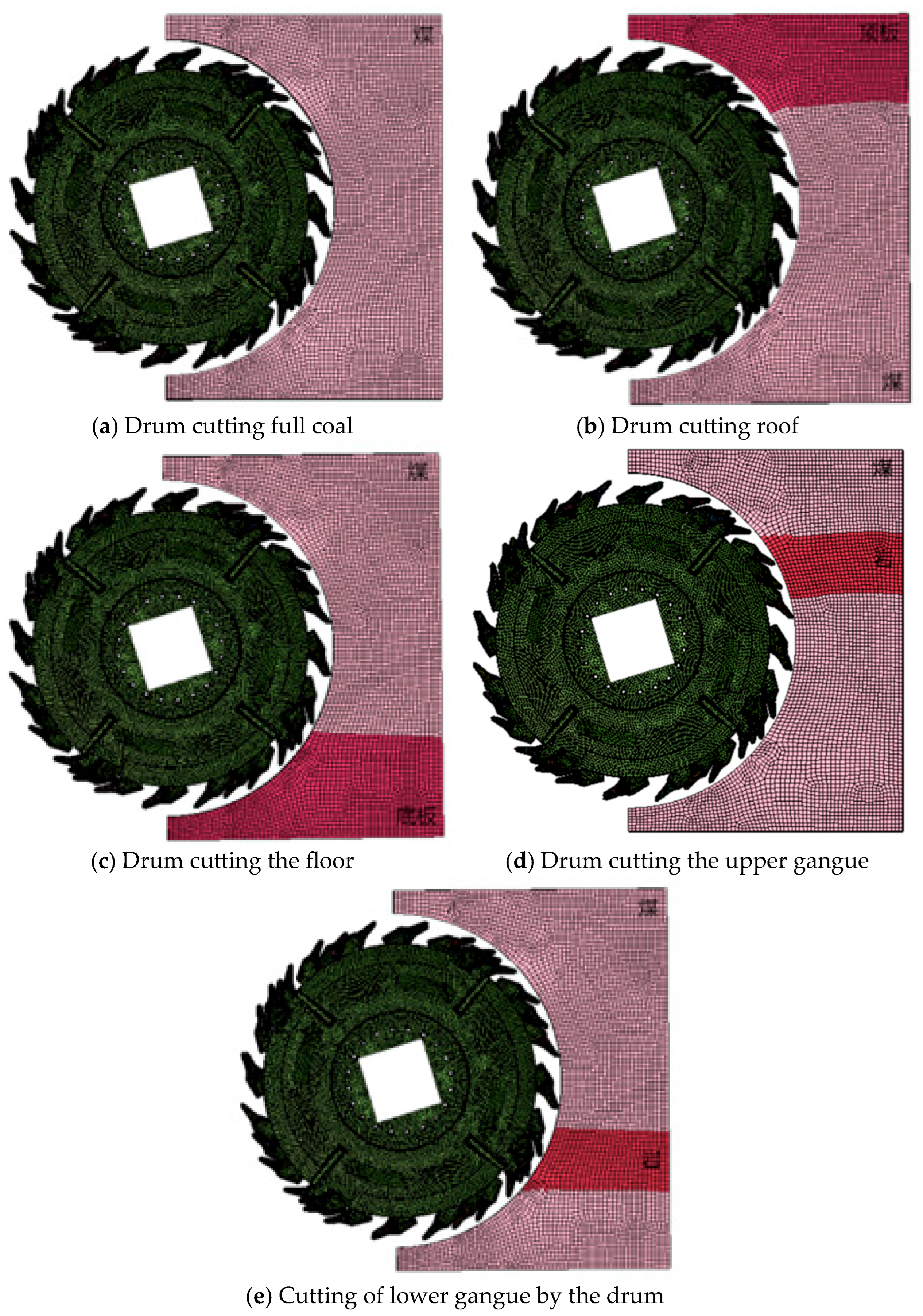
Following a multi-software co-simulation approach, parametric modeling of the shearer drum assembly was first completed in SolidWorks. The model was then exported as an intermediate file in “x_t” format to ensure the integrity of geometric topological features during cross-platform transfer. After importing the model into the HyperMesh pre-processing platform, geometry cleanup—including the elimination of minor fillets and interference surfaces—was performed prior to meshing. To balance computational accuracy and efficiency, tetrahedral elements were applied to the picks and drum, while hexahedral elements were used for the coal wall; the resulting finite element model is shown in Figure 1.
Given the continuously varying geological conditions at coal mining faces and the resulting complexity of actual shearer operating conditions, simulation analyses were conducted for the drum under six representative conditions: full-coal cutting, full-rock cutting, roof cutting, floor cutting, upper gangue cutting, and lower gangue cutting.

2.2. Material Definition and Failure Criteria

Given that the strength of the drum and cutting picks significantly exceeds that of the coal wall during the cutting process, Material Model 20 (Rigid Body) was employed to simulate the drum and picks. Translational degrees of freedom in the vertical direction and the direction perpendicular to the working face, as well as rotational degrees of freedom in the horizontal and vertical directions, were constrained. The coal wall was simulated using Material Model 272 (RHT), with material parameters listed in Table 1.
The material parameters listed in Table 1 were derived from laboratory tests on core samples collected from the Shanxi mining area. For coal, the uniaxial compressive strength (UCS) of 20 MPa and elastic modulus of 2.4 GPa represent average values for medium-hard bituminous coal. The gangue and roof strata, both with a UCS of 53 MPa and an elastic modulus of 2.99 GPa, correspond to medium-hard sandstone interlayers commonly encountered in the same geological formation. The floor strata, with a UCS of 75 MPa and elastic modulus of 5.47 GPa, represent hard siltstone. We acknowledge that geological materials exhibit inherent variability; the values reported here are mean values from a minimum of five independent core samples for each lithology, with measured UCS ranges of 18–23 MPa (coal), 48–57 MPa (gangue/roof), and 70–79 MPa (floor). These ranges have been included in the revised text to better reflect the natural variability of the materials.
Since the RHT model does not incorporate an intrinsic failure criterion, a separate failure mechanism must be introduced. The failure of coal and rock is governed by MAT_ADD_EROSION, a keyword that allows elements to be deleted when specified criteria are reached—typically when accumulated plastic strain or tensile stress exceeds predefined thresholds. This approach effectively replicates the brittle fragmentation behavior observed in coal and rock cutting. The parameter settings are listed in Table 2.
In Table 2, the repeated value “1234” follows the standard LS-DYNA convention for the MAT_ADD_EROSION keyword, indicating that the corresponding failure criterion is not activated (i.e., the default inactive status). The actual element erosion in this study is governed by the plastic strain criterion (EFFEPS = 0.01) and the tensile stress limit (SIGP1 = 0.02 MPa), as highlighted in the table. The RHT material parameters for coal followed the standard parameterization recommended in the LS-DYNA user manual for brittle geomaterials, with calibrated values as listed in Table 1. The complete parameter set can be found in the reference manual [LS-DYNA Keyword User’s Manual, Volume II, Material Models].

2.3. Contact Algorithms and Boundary Conditions

The LS-DYNA R11.0 software provides a comprehensive array of contact algorithms, categorized into three fundamental types based on the characteristics of the contacting entities: single-surface contact, node-to-surface contact, and surface-to-surface contact. The dynamic process of coal and rock fragmentation by shearer picks is essentially a problem of high-velocity impact and penetration mechanics. Given these characteristics, this study employs the CONTACT_ERODING_SURFACE_TO_SURFACE keyword to model the pick–coal/rock interaction. This contact algorithm effectively simulates contact behavior during continuous material failure, with parameter settings detailed in Table 3.
In the simulation, the haulage direction is defined as the positive X-axis, the drum rotation axis aligns with the Z-axis, and the cutting depth direction corresponds to the Y-axis. The material regions (coal, gangue, roof, and floor) are distinguished by different element sets and material property assignments in the finite element model, with full displacement constraints applied to the bottom and rear boundaries as described below. The motion of the shearer drum during coal and rock cutting comprises a combination of rotation and translation, while the coal wall remains stationary. In LS-DYNA, the drum motion is driven by a predefined curve via the BOUNDARY_PRESCRIBED_MOTION_RIGID keyword; therefore, a motion curve was first defined using the DEFINE_CURVE keyword, with a traction speed of 8.4 m/min, a drum rotational speed of 40 r/min, and a simulation duration of 3 s. To ensure kinematic synchronization between the shearer drum and the pick system, the CONSTRAINT_RIGID_BODIES keyword was employed to establish a rigid connection between them.
To effectively simulate the infinite medium characteristics of the coal wall, full displacement constraints were applied to the top, bottom, lateral, and rear boundaries of the coal wall model. Additionally, the BOUNDARY_NON_REFLECTING keyword was introduced in regions unaffected by the picks to establish non-reflecting boundary conditions, thereby suppressing the reflection effects of dilatational and shear waves—a critical step for avoiding artificial wave reflections that could contaminate the stress fields near the cutting zone.
To address numerical stability issues in contact calculations, key parameters in CONTROL_CONTACT were adjusted by setting the contact penalty scale factor SLSFAC to 0.01 (rather than the default value), which is commonly adopted in LS-DYNA erosion contact simulations for brittle materials to maintain numerical stability when element deletion occurs. which effectively improved convergence regarding contact interface penetration. The single-point integration method in finite element analysis can significantly reduce computational costs; however, if the resulting hourglass problem is not effectively controlled, the computational results will be unreliable. In LS-DYNA, the temporal evolution of Hourglass Energy and Total Energy can be monitored. Generally, if the Hourglass Energy exceeds 10% of the Total Energy, hourglass control must be implemented. In all simulations conducted in this study, the hourglass energy remained below 5% of the total energy, well within the acceptable threshold. To record the output results, the D3PLOT card was defined to enable data acquisition (stress, strain, and deformation) at an output time step of 0.01 s, ensuring high-precision data for subsequent dynamic load and energy evolution analyses.

2.4. Model Validation

To assess the reliability of the established finite element model, the simulation results for the pure coal cutting condition were compared against theoretical calculations derived from classical cutting theory. Under fixed shearer parameters, the cutting resistance of the spiral drum is generally estimated from the cutting power. The resultant force on the drum can be resolved into two components: the cutting resistance F z , which acts perpendicular to the haulage direction and is concentrated at the pick tips at the drum’s midsection, and the traction resistance F z , which acts opposite to the haulage direction. The cutting resistance is calculated as:
F z = 1.91 × 10 7 N H η n D c
where η is the transmission efficiency of the cutting unit; N H is the rated power of the cutting motor (kW); D c is the drum diameter (mm); and n is the drum rotational speed (rad/min). Using Equation (1) with the parameters for pure coal cutting (UCS of coal = 20 MPa), the theoretical cutting resistance was calculated as 91 kN. The corresponding simulation result during the stable cutting stage yielded a maximum cutting resistance of 87.0245 kN. The theoretical calculation (91 kN) represents the nominal steady-state resistance, while the simulated peak value is reported here as it reflects the maximum loading condition of practical interest for structural design. The comparison between these two values, together with the mean simulated value during the stable stage, provides mutual validation of the numerical model. The relative error between the two is approximately 4.37%, which falls within the acceptable range for engineering-scale numerical simulations of rock cutting processes. This consistency confirms the validity of the established finite element model and provides a reliable basis for subsequent analyses of more complex conditions, including gangue-bearing seams, roof cutting, and floor cutting.
It should be acknowledged that the numerical model involves several simplifications: the RHT model relies on calibrated parameters that may not fully represent material heterogeneity; MAT_ADD_EROSION introduces mesh-size sensitivity; the penalty-based contact formulation simplifies pick–rock interaction; and thermal effects and twin-drum operation are not considered. Despite these, the 10.28% relative error in model validation supports its reliability for the comparative analyses presented. A systematic mesh convergence study was beyond the scope of this work; however, the good agreement between the simulated and theoretical results indirectly confirms that the current mesh resolution is adequate for the comparative analyses performed. Future work will include a dedicated mesh sensitivity analysis to further quantify the effects of mesh refinement.

3. Loads on the Shearer Drum Under Different Operating Conditions

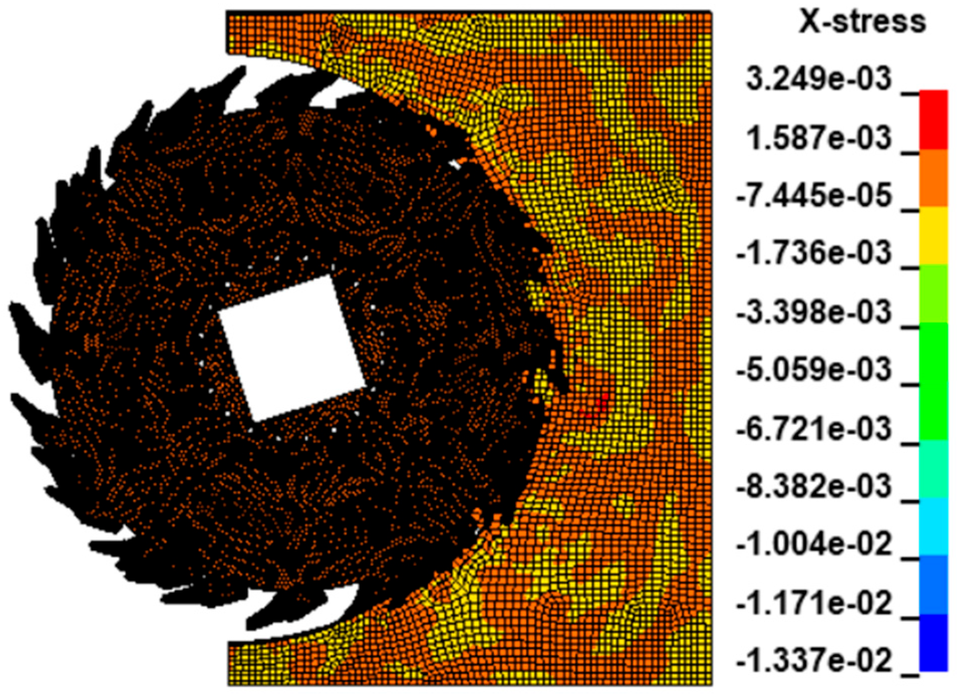
Simulation conditions were configured as follows: drum rotation speed of 40 r/min, haulage speed of 8.4 m/min, UCS of coal at 20 MPa, and cutting height of 2 m. The UCS values for rock, gangue, and roof were all set to 53 MPa, while that for the floor was set to 75 MPa. The thicknesses of the gangue and the roof/floor were set to 425 mm and 575 mm, respectively. Upon completion of parameter configuration, the simulation was conducted. Subsequently, the D3PLOT file was opened to examine the simulation results. Variations in load and stress experienced by the front and rear drums during the cutting of pure coal, gangue, roof, and floor could be analyzed individually. The stress contour map during the cutting process is illustrated in Figure 2. As the pick continuously penetrates the coal-rock medium, elements in the vicinity of the coal wall undergo a dynamic stress–strain evolution. When the accumulated elastoplastic deformation energy within an element reaches the material‘s ultimate bearing threshold, the element failure criterion is triggered, causing the element to be automatically removed from the system based on damage mechanics principles. This dynamic failure process ensures that the pick tip remains continuously exposed to fresh coal-rock interfaces, thereby establishing a cyclic fragmentation mechanism. The following analysis focuses on the loads acting on the front drum under various operating conditions. To ensure objective and consistent identification of the stable cutting stage across all operating conditions, we adopted the following criterion: the stable stage was defined as the time interval during which the sliding-window mean of the cutting resistance (window size: 100 ms) remained within ±10% of the overall mean over a sustained period of at least 500 ms, and the fluctuation amplitude ceased its initial monotonic growth. This criterion was applied uniformly to all five operating conditions to enable fair comparison of the statistical load characteristics.

3.1. Drum Cutting of Pure Coal

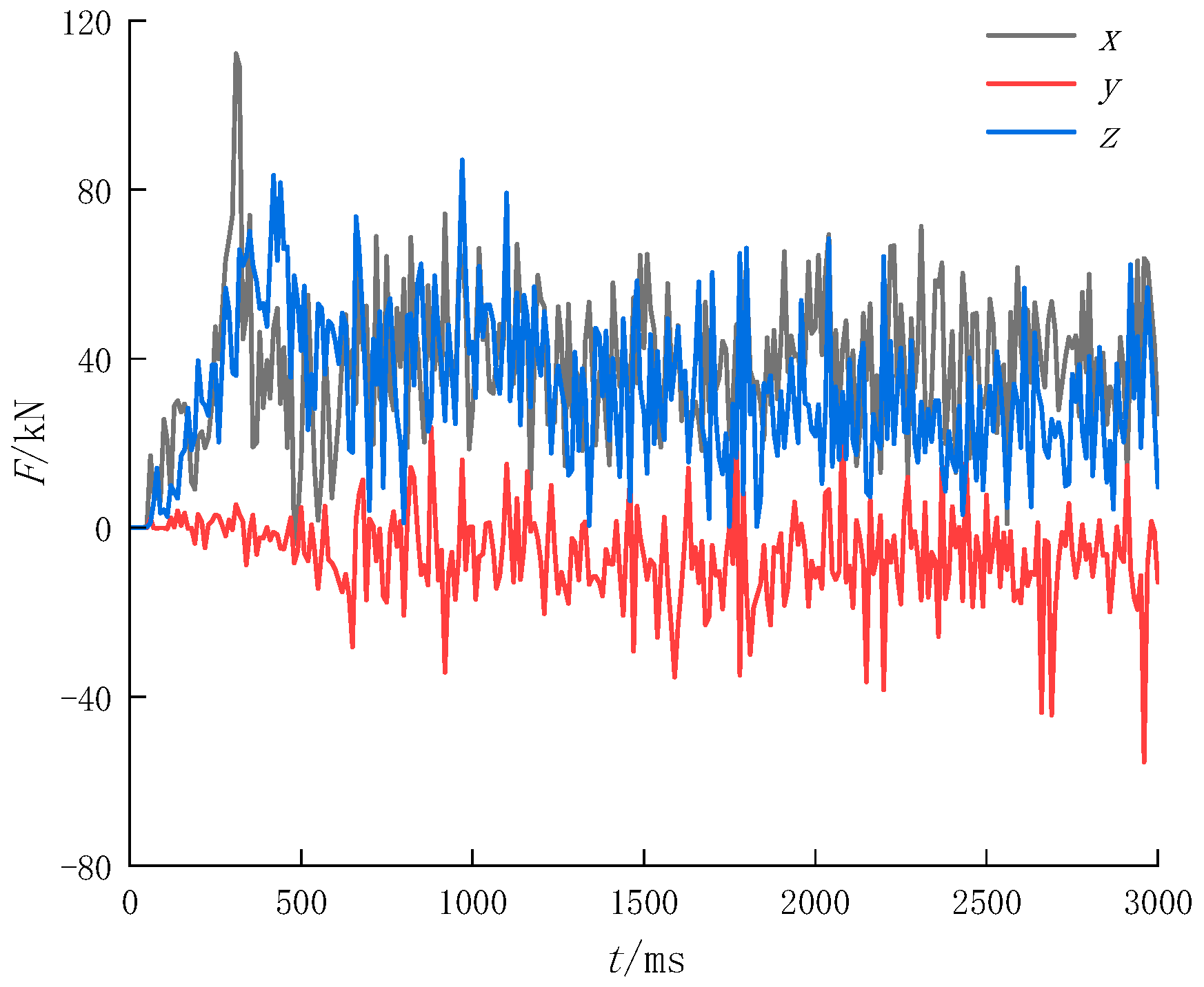
The three-directional load data acting on the drum were exported from LS-PrePost and plotted using Origin. The three-directional loads experienced by the drum during pure coal cutting are shown in Figure 3.
As shown in Figure 3, during the cutting of pure coal by the drum, both the cutting resistance and traction resistance initially increase and exhibit a relatively large peak. This is attributed to the small number of picks engaged in cutting at the initial stage of shearer operation, which results in high loads on individual picks and random coal fragmentation, thereby causing instability in the cutting process. Subsequently, as time progresses, the number of active picks increases, and the drum enters a stable cutting state. The drum reaches this stable cutting state at approximately 750 ms. In this state, the load on the drum remains relatively constant, resulting in smooth fluctuations in the load curves. Specifically, both the traction resistance and cutting resistance fluctuate unidirectionally, whereas the lateral force oscillates between positive and negative values due to uneven loading on both sides of the picks. To better analyze the triaxial loads acting on the drum during pure coal cutting, a statistical analysis was performed on the data from the stable cutting stage, with the results presented in Table 4.
As shown in Table 4, during the stable cutting phase of the drum, the maximum traction resistance is 74.2697 kN with a mean value of 40.3384 kN; the maximum cutting resistance is 87.0245 kN with a mean value of 30.923 kN; and the maximum lateral force is 30.0948 kN with a mean value of −7.565 kN. The relatively large standard deviations of all three components (14.08 kN, 11.75 kN, and 15.92 kN, respectively) reflect the inherent stochasticity of the coal fragmentation process, which is governed by the random distribution of micro-defects within the coal mass. This statistical characterization of the stable-stage loads provides a baseline reference for evaluating the more complex conditions discussed below.

3.2. Drum Cutting of Gangue

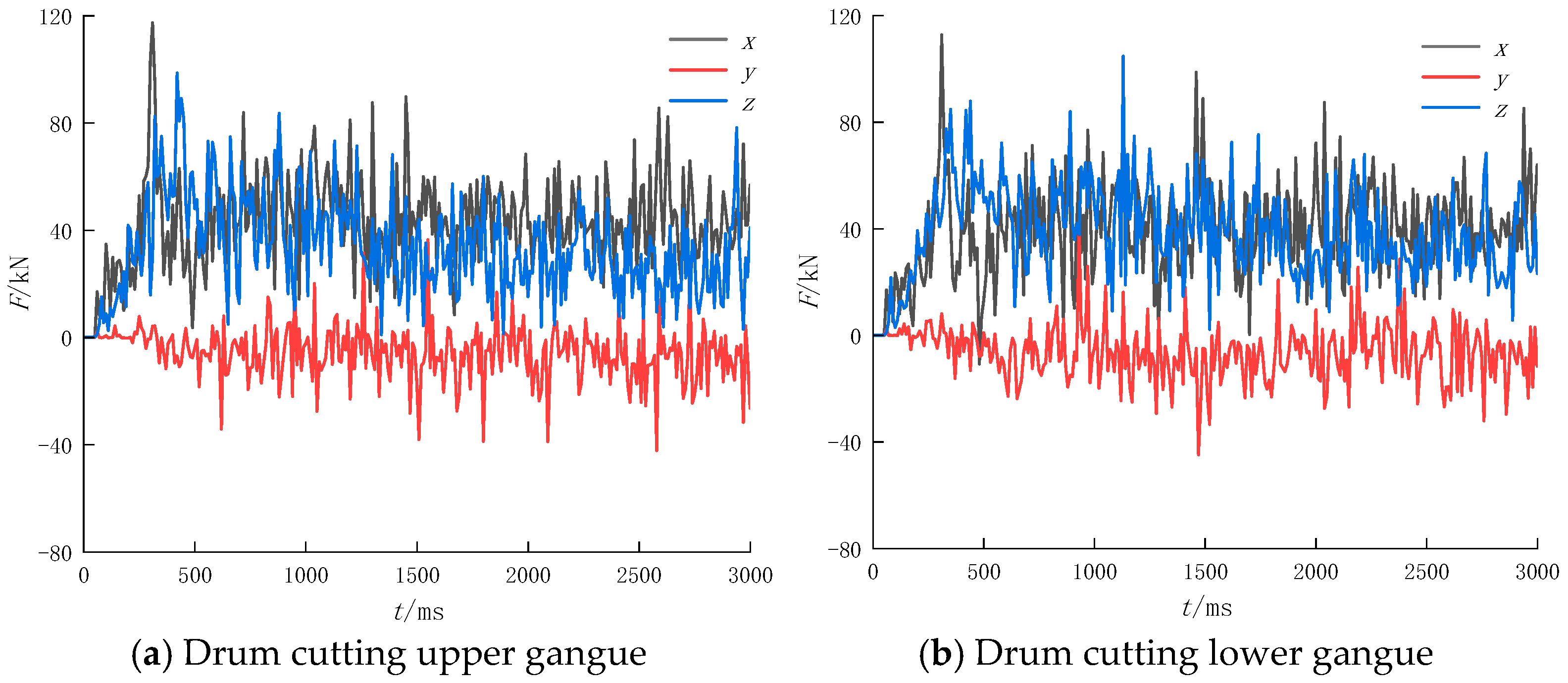
The triaxial load data acting on the drum were exported from LS-PrePost and plotted using Origin. The loads experienced by the drum during cutting of gangue at different positions are shown in Figure 4.
As shown in Figure 4, the position of the gangue has little effect on the patterns of the three-directional loads acting on the cutting drum during cutting. To determine the specific influence of gangue position on the load magnitudes, a statistical analysis was conducted, and the results are presented in Table 5.
As shown in Table 5, when the gangue is located in the upper section, the maximum and mean traction resistances are 117.408 kN and 43.0113 kN, respectively, while the maximum and mean cutting resistances are 98.7089 kN and 33.445 kN, respectively. When the gangue is located in the lower section, the corresponding values are 112.852 kN and 39.0583 kN for traction resistance, and 104.815 kN and 38.4538 kN for cutting resistance. These results reveal a distinct pattern: upper gangue maximizes traction resistance, whereas lower gangue maximizes cutting resistance.
This differential effect can be explained by the mechanics of the cutting process. When the gangue layer is positioned in the upper portion of the seam, the higher-strength material (UCS = 53 MPa) is concentrated near the roof, which increases the frictional resistance along the drum’s axial direction as the picks shear through the harder material. This elevated axial resistance manifests primarily as increased traction resistance. Conversely, when the gangue is located in the lower portion, the harder material directly intersects the primary cutting path of the picks, thereby offering greater resistance to the rotational cutting motion, which is reflected as increased cutting resistance. This finding has practical implications: in seams where gangue is known to occur predominantly in the upper or lower section, drum designers should prioritize strengthening the corresponding load-bearing components.
Furthermore, the number of picks simultaneously engaged with the gangue layer differs between the two scenarios. When the gangue is in the upper section, the harder material is intercepted by picks along the upper arc of the drum trajectory, where the cutting direction has a larger component opposing the haulage direction, thereby elevating the traction resistance. In contrast, lower gangue is engaged near the bottom of the drum rotation, where the cutting force aligns more directly with the cutting resistance. These geometric and engagement differences, together with the load distributions shown in Figure 5, provide additional support for the observed differential effects.

3.3. Drum Cutting of Roof and Floor

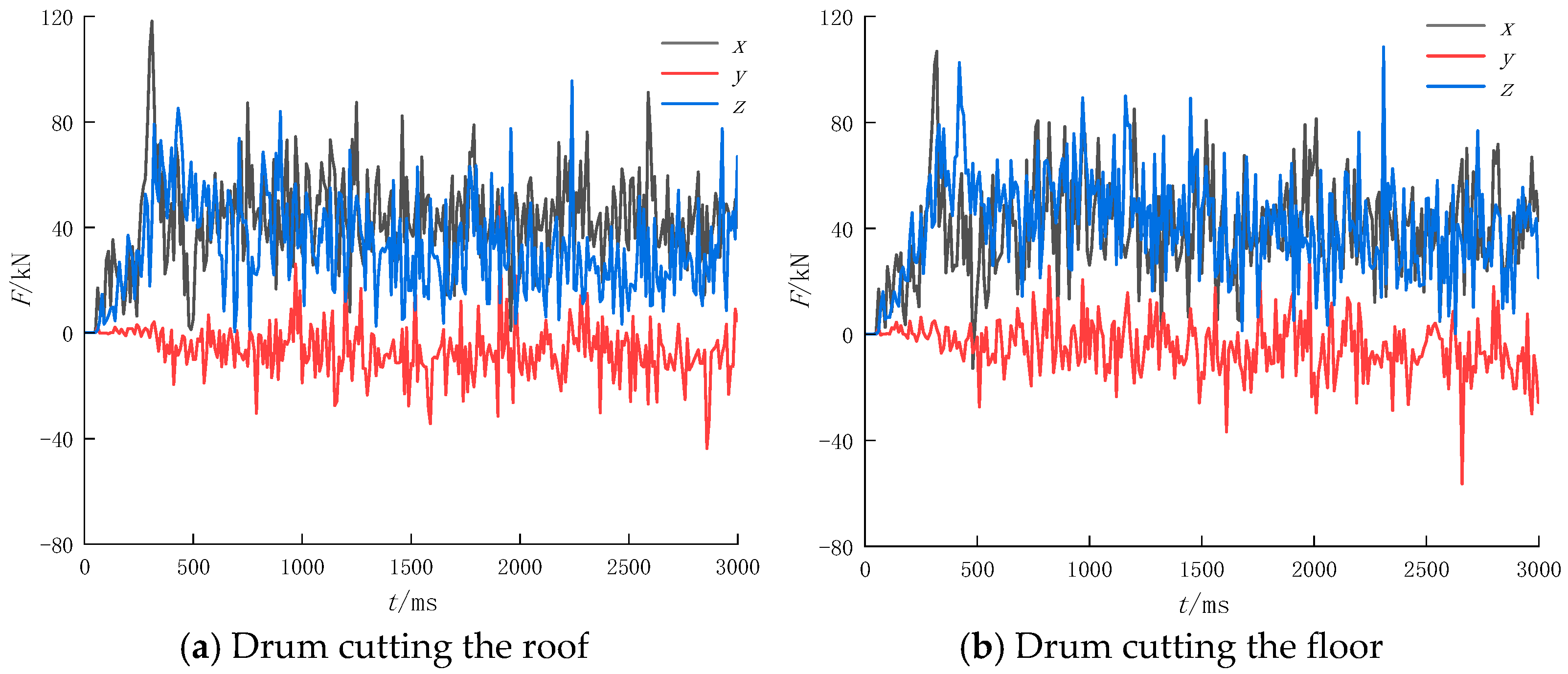
The triaxial load data acting on the drum were exported from LS-PrePost and plotted using Origin. The triaxial loads experienced by the drum during stable cutting of the roof and floor are illustrated in Figure 5. As shown in Figure 5, although the UCS of the floor exceeds that of the roof, the mean traction resistance during stable roof cutting is greater than that during floor cutting. Similarly, when the gangue layers possess identical UCS values, the traction load encountered during cutting of the upper gangue layer exceeds that of the lower gangue layer. This trend persists despite the higher UCS of the floor relative to the roof, indicating that the cutting position exerts a more significant influence on the traction load. Nevertheless, the cutting resistance encountered during floor cutting is invariably greater than that during roof cutting.
The triaxial load data from the drum cutting the roof and floor were statistically analyzed, and the results are presented in Table 6.
As shown in Table 6, when the drum cuts the roof, the maximum and mean traction resistances acting on the drum are 118.118 kN and 42.1644 kN, respectively, while the maximum and mean cutting resistances are 95.5622 kN and 32.1723 kN, respectively; when the drum cuts the floor, the maximum and mean traction resistances acting on the drum are 106.84 kN and 38.8619 kN, respectively, while the maximum and mean cutting resistances are 108.387 kN and 41.0849 kN, respectively. To verify that the observed differences are not due to random variation, we performed t-tests comparing the mean load values between key operating conditions (upper vs. lower gangue, roof vs. floor). The results confirm that the differences are statistically significant (p < 0.05).

4. Ensemble Empirical Mode Decomposition Method

As an adaptive signal analysis method, Ensemble Empirical Mode Decomposition (EEMD) can decompose complex nonlinear and non-stationary signals into multiple physically meaningful Intrinsic Mode Functions (IMFs), and has been widely applied in various fields.

4.1. Fundamental Principles of EEMD

The Ensemble Empirical Mode Decomposition (EEMD) method was developed based on Empirical Mode Decomposition (EMD). By identifying local extrema of a signal, constructing upper and lower envelopes, and calculating their mean, EMD decomposes the signal into several IMF components and a residual term [20,21]. During the EMD process, each IMF component must satisfy strict criteria: the sum of the number of extrema and zero crossings across the entire signal domain must be even, and the mean of the upper and lower envelopes must be zero. However, EMD suffers from mode mixing when processing complex signals, where components of different frequencies may be mixed within a single IMF, thereby compromising the accuracy of the decomposition results. To address this issue, EEMD introduces the concept of ensemble averaging. Its core principle involves adding white noise of varying amplitudes to the original signal, performing multiple EMD trials, and averaging the results, which effectively mitigates mode mixing and enhances the stability and reliability of the decomposition.

4.2. Ensemble Empirical Mode Decomposition

EEMD Procedure: Parameter Initialization: Set the standard deviation of the added Gaussian white noise (Nstd) and the number of ensemble trials for EEMD (NE) [21,22]. Noise Addition and Decomposition: Add Gaussian white noise with varying amplitudes to the original signal and perform multiple EMDs to obtain a set of IMF matrices. Ensemble Averaging: Average the IMF matrices obtained from the multiple decompositions to derive the final IMF components. Post-processing: Perform further processing on the IMF components according to specific requirements, such as noise component removal or feature extraction. During the coal and rock cutting process of a shearer, the triaxial loads acting on the drum (traction resistance, lateral force, and cutting resistance) are critical factors influencing the performance and stability of the machine. Compared to conventional stationary signals, these signals typically exhibit significant non-stationarity and nonlinear coupling characteristics, making it difficult for traditional time-frequency analysis methods to accurately capture their dynamic evolution patterns. Ensemble Empirical Mode Decomposition (EEMD), as a data-driven adaptive decomposition technique, can effectively extract several IMFs embedded in the signal through a noise-assisted analysis strategy. In this study, EEMD is applied to the triaxial resistance data acquired from the drum under various operating conditions. Among the three directional load components, the traction resistance was chosen as the primary subject for EEMD analysis because it exhibited the most pronounced and consistent differences across the five operating conditions, making it the most suitable signal for demonstrating the capability of the EEMD–sample entropy approach. The same analysis can be readily extended to the other two load components in future work. The waveform of each IMF component is plotted, and the sample entropy of each IMF is calculated to analyze the complexity and regularity of the signals.

4.2.1. Data Import and Preprocessing

MATLAB R2020a code was developed to perform EEMD. The EEMD implementation followed these steps: (i) Gaussian white noise with a standard deviation of 0.2 times that of the original signal was added to the traction resistance data; (ii) the noise-added signal was decomposed by EMD to obtain a set of IMFs; (iii) steps (i) and (ii) were repeated 100 times with different noise realizations; (iv) the final IMFs were obtained by averaging the corresponding IMFs across all 100 trials. For sample entropy calculation, the embedding dimension was set to 2 and the similarity tolerance r was set to 0.2 times the standard deviation of each IMF signal. Triaxial load data acting on the drum under various operating conditions were imported from an Excel file. The dataset comprises four columns: time, traction resistance, lateral force, and cutting resistance, which were subjected to EEMD analysis.
The traction resistance signal was decomposed using the EEMD method to obtain multiple IMF components. The specific procedures are as follows: First, parameter initialization: the standard deviation of the added Gaussian white noise (Nstd) was set to 0.2, and the number of ensemble trials (NE) was set to 100. The choice of Nstd = 0.2 and NE = 100 follows common practice in EEMD applications; this combination provides a good balance between decomposition accuracy and computational cost, with the added noise amplitude falling within the widely recommended range of 0.1–0.4 times the signal’s standard deviation. Second, noise addition and decomposition: Gaussian white noise with varying amplitudes was added to the original signal, and EMD was performed repeatedly to generate multiple IMF matrices. Third, ensemble averaging: the IMF matrices obtained from the repeated decompositions were averaged to yield the final IMF components.
To validate the quality of the EEMD, we verified that all extracted IMF components satisfy the two standard criteria for Intrinsic Mode Functions: (i) the number of extrema and the number of zero crossings differ by at most one throughout the entire signal, and (ii) the mean of the upper and lower envelopes is approximately zero at every point. The sifting stopping criterion was set to a standard deviation threshold of 0.2 between consecutive iterations. Regarding the choice of EEMD over alternative decomposition methods, we note that wavelet transform requires preselection of a basis function that may not optimally match the signal’s physical characteristics, while Variational Mode Decomposition (VMD) imposes strong assumptions about the number and bandwidth of modal components. Given the highly nonlinear and non-stationary nature of our traction resistance signals, with no prior knowledge of their frequency content, EEMD’s adaptive, data-driven framework offers a more flexible and physically interpretable decomposition. Furthermore, the distinct sample entropy patterns across different cutting conditions provide indirect evidence that the decomposition has successfully extracted physically meaningful components, as otherwise such clear discriminative patterns would not emerge.

4.2.2. Waveforms of IMF Components and Sample Entropy Calculation

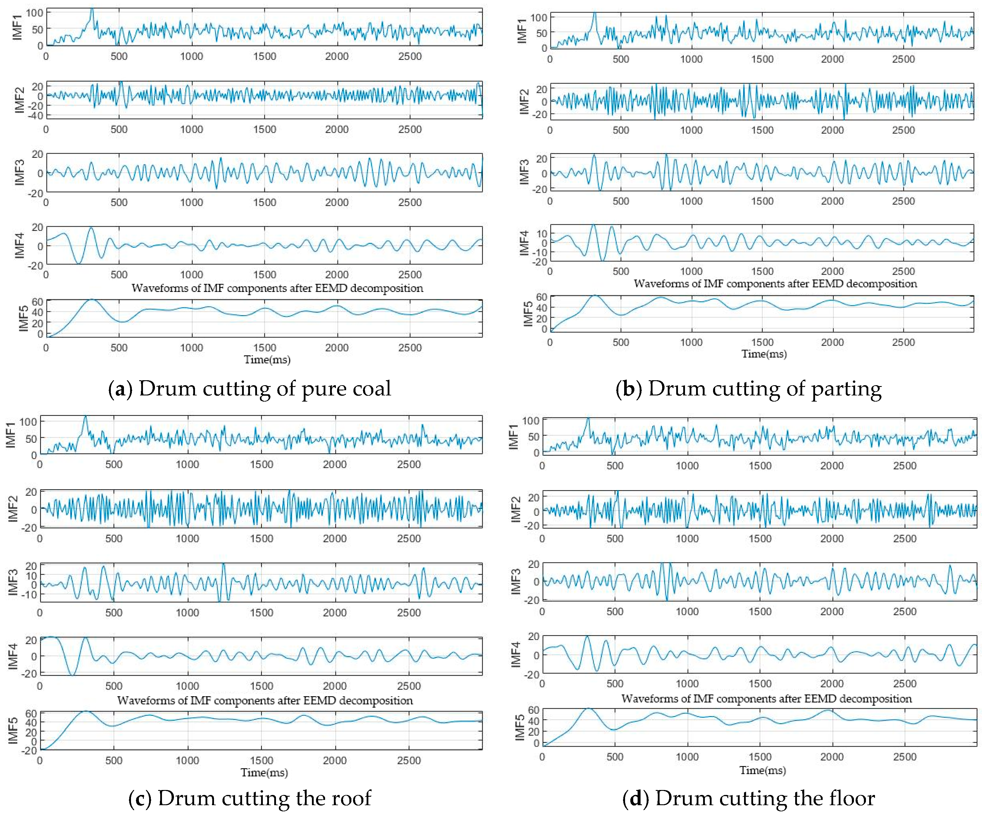
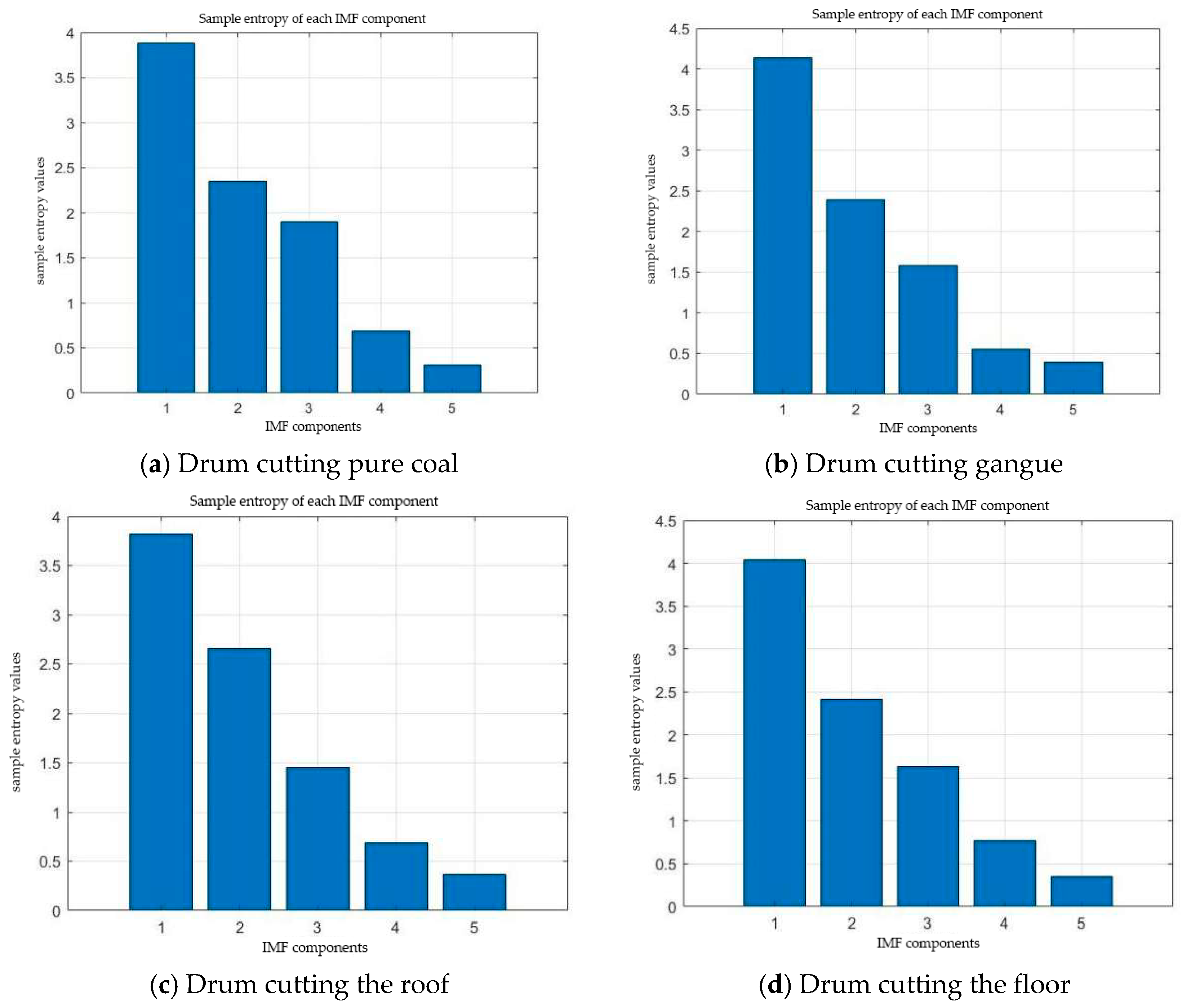
Taking the traction resistance of a drum cutter under various operating conditions as an example, the signal was analyzed following EEMD, with the results presented in Figure 6. Waveforms were plotted for each IMF component, with the abscissa representing time (in milliseconds) and the ordinate representing the amplitude of the respective IMF component. Observation of these waveforms provides intuitive insight into the frequency characteristics and fluctuation patterns of each IMF component. Subsequently, the sample entropy of each IMF component was calculated to quantify its complexity and regularity. The sample entropy was computed using the following parameters: an embedding dimension (dim) of 2 and a similarity tolerance (r) set to 20% of the standard deviation of the signal. The calculated sample entropy values for each IMF component are shown in Figure 7.
Based on the waveforms and sample entropy values of the IMF components derived from the traction resistance acting on the drum, it is evident that regardless of the operating condition, the decomposed IMF components exhibit similar patterns: IMF1 represents high-frequency components containing substantial noise and rapid fluctuations; IMF2 comprises medium-to-high frequency components with large fluctuation amplitudes, potentially including periodic elements; IMF3 consists of medium-frequency components with relatively regular fluctuations, likely encompassing the dominant periodic components; IMF4 corresponds to low-frequency components with smaller fluctuation amplitudes, possibly reflecting slowly varying trends; and IMF5, as the lowest-frequency component, primarily reflects the overall trend with relatively stable fluctuations. Nevertheless, distinct cutting characteristics arise due to differences in specific cutting conditions.
The fluctuation of the traction resistance signal for pure coal is relatively regular, with IMF3 and IMF4 exhibiting large amplitudes, indicating distinct periodic components during the cutting of pure coal. Gangue: The mid-frequency component (IMF3) of the traction resistance signal shows significant fluctuations, suggesting abundant mid-frequency periodic components during gangue cutting. Roof: The low-frequency components (IMF4 and IMF5) of the traction resistance signal fluctuate relatively steadily, indicating predominant low-frequency trend components during roof cutting. Floor: The high-frequency components (IMF1 and IMF2) of the traction resistance signal are pronounced, implying greater noise and rapid fluctuations during floor cutting.
A comparison of the EEMD results of traction resistance acting on the shearer drum under different operating conditions reveals the complexity of traction resistance signals during cutting processes. The signal obtained from pure coal cutting is relatively regular, whereas that from floor cutting is more complex, containing greater high-frequency noise and rapid fluctuations. The sample entropy values in Figure 7 further quantify this distinction: the high-frequency IMF1–2 components for floor cutting exhibit the highest entropy values among all conditions, indicating that floor cutting generates the most complex load signals, which may be associated with more severe impact characteristics. Physically, higher entropy in these high-frequency components reflects greater signal irregularity, corresponding to more intense intermittent impact loading due to the higher strength and constrained boundary of the floor strata—suggesting that drum design for floor cutting should prioritize impact resistance.

5. Conclusions

The triaxial loads on the cutting drum under various operating conditions were investigated. A three-dimensional model of the drum cutting coal and rock was established using SolidWorks, and a finite element model was generated via the pre-processing software HyperMesh. Simulation analyses of the drum under different operating conditions were conducted using LS-DYNA, and ensemble empirical mode decomposition (EEMD) was applied to decompose the triaxial loads.
(1)
During coal and rock cutting by the drum, both the cutting resistance and traction resistance initially increase, exhibiting a relatively large peak. Subsequently, as time progresses and the number of active picks increases, the drum enters a stable cutting state. When cutting coal containing gangue, the load on the drum varies with the position of the gangue; under otherwise identical conditions, the gangue position significantly affects the magnitude of the cutting resistance. Coal and rock strength has a pronounced effect on the load. The position of the gangue also exerts a significant influence: upper gangue results in the maximum traction resistance, whereas lower gangue leads to the maximum cutting resistance. Floor cutting induces high loads due to its high compressive strength. The theoretical and simulated cutting resistances for pure coal cutting are 91 kN and 87.0245 kN, respectively, with a relative error of approximately 4.37%, validating the effectiveness of the drum cutting simulation method.
(2)
EEMD analysis of the triaxial loads acting on the drum reveals that the complexity of the traction resistance signal varies across different cutting conditions, with the load during floor cutting exhibiting substantial high-frequency noise and significant fluctuations. The sample entropy of the IMF components obtained via EEMD indicates that the high-frequency components IMF1–2 possess the highest complexity, suggesting the presence of impact characteristics during the cutting process. Among all operating conditions, floor cutting yields the highest sample entropy values for IMF1–2, suggesting that floor cutting imposes the most severe impact loading among the five conditions examined in this study. Based on these findings, we recommend that drum design for seams with upper gangue should strengthen the haulage-direction structural components to withstand elevated traction resistance, while for lower gangue or floor cutting, enhancing the cutting picks and drum body against impact and fatigue is prioritized. For adaptive cutting control, the distinct sample entropy patterns across different cutting media suggest that real-time monitoring of load signal complexity could serve as a basis for automatic recognition of cutting conditions and adjustment of drum speed and haulage speed accordingly.

Author Contributions

Conceptualization, D.L. and Y.G.; Methodology, J.F. and Y.G.; Validation, J.F.; Formal analysis, D.L. and Y.G.; Investigation, J.F., D.L., X.H., R.H. and Y.G.; Resources, J.F., D.L. and X.H.; Data curation, J.F., X.H. and R.H.; Writing—original draft, X.H., R.H. and Y.G.; Writing—review & editing, J.F., X.H., R.H. and Y.G.; Project administration, D.L. All authors have read and agreed to the published version of the manuscript.

Funding

This research received no external funding.

Data Availability Statement

The original contributions presented in this study are included in the article. Further inquiries can be directed to the corresponding author.

Conflicts of Interest

Author Jiaxing Fu was employed by the company Chinese Institute of Coal Science. Author Yang Gao was employed by the company CCRl (Beijing) Testing Technology Co., Ltd. The remaining authors declare that the research was conducted in the absence of any commercial or financial relationships that could be construed as a potential conflict of interest.

References

  1. Liu, J.; Zeng, F.; Zhang, C. Research on the influence of cutting surface characteristics on the cutting load of the conical pick. J. Phys. Conf. Ser. 2024, 2791, 397–412. [Google Scholar] [CrossRef] [Scilit]
  2. Zhang, M.; Zhao, L.; Li, M.; Tian, Z. Analysis and experimental study on the vibration characteristics of the spiral drum of a shearer based on two-way coupling method. Coal Sci. Technol. 2024, 52, 200–216. [Google Scholar]
  3. Tian, Z.; Jing, S.X.; Zhao, L.J.; Gao, S.; Zhang, C.G. Research on cutting performance of spiral drum of shearer in thin coal seam. J. Henan Polytech. Univ. (Nat. Sci.) 2020, 39, 80–84. [Google Scholar]
  4. Liu, X.N.; Zhao, L.J.; Zhou, W.C.; Liu, H.M. Strength analysis of shearer drum cutting coal-rock with gangue based on LS-DYNA. J. Mech. Strength 2019, 41, 1493–1498. [Google Scholar]
  5. Zhao, L.; Wang, Y.; Wang, B. Analysis and prediction of working performance of shearer spiral drums under coal seam with gangue. China Mech. Eng. 2021, 32, 976–986. [Google Scholar]
  6. Gao, K.D.; Zhang, X.D.; Sun, L.Q.; Zeng, Q.; Liu, Z. Loading performance of a novel shearer drum applied to thin coal seams. Energies 2021, 14, 358. [Google Scholar] [CrossRef] [Scilit]
  7. Chen, H.; Yang, X.; Mao, J.; Song, Q.S.; Yuan, Z. Vibration characteristics analysis of shearer under oblique cut on drum test load. J. Vib. Meas. Diagn. 2018, 38, 240–247. [Google Scholar]
  8. Jamshidi, E.; Kianoush, P.; Hosseini, N.; Adib, A. Scaling-up dynamic elastic logs to pseudo-static elastic moduli of rocks using a wellbore stability analysis approach in the Marun oilfield, SW Iran. Sci. Rep. 2024, 14, 19094. [Google Scholar] [CrossRef] [Scilit] [PubMed]
  9. Onate, E.; Rojek, J. Combination of discrete element and finite element methods for dynamic analysis of geomechanics problems. Comput. Methods Appl. Mech. Eng. 2004, 193, 3087–3128. [Google Scholar] [CrossRef] [Scilit]
  10. Cho, J.-W.; Jeon, S.; Yu, S.-H.; Chang, S.-H. Optimum spacing of TBM disc cutters: A numerical simulation using the three-dimensional dynamic fracturing method. Tunn. Undergr. Space Technol. Inc. Trenchless Technol. Res. 2009, 25, 654–664. [Google Scholar] [CrossRef] [Scilit]
  11. Jin, G.D. Analysis of rock-breaking mechanism by disc cutters on full-face rock tunnel boring machines (Part II). Power Stn. Constr. Mach. 1981, 58, 21–27. [Google Scholar]
  12. Dewangan, S.; Chattopadhyaya, S.; Hloch, S. Wear assessment of conical pick used in coal cutting operation. Rock Mech. Rock Eng. 2015, 48, 2129–2139. [Google Scholar] [CrossRef] [Scilit]
  13. Dewangan, S.; Chattopadhyaya, S. Characterization of wear mechanisms in distorted conical picks after coal cutting. Rock Mech. Rock Eng. 2016, 49, 225–242. [Google Scholar] [CrossRef] [Scilit]
  14. Pradeep, L.; Menezes, M.R.; Lovell, I.V.; Avdeev, C.; Higgs, F. Studies on the formation of discontinuous rock fragments during cutting operation. Int. J. Rock Mech. Min. Sci. 2014, 71, 131–142. [Google Scholar] [CrossRef] [Scilit]
  15. Menezes, P.L. Influence of friction and rake angle on the formation of built-up edge during the rock cutting process. Int. J. Rock Mech. Min. Sci. 2016, 88, 175–182. [Google Scholar] [CrossRef] [Scilit]
  16. Korinets, A.R.; Chen, L.; Alehossein, H.; Lim, W. DIANA modeling of a rolling disc cutter and rock indentation. Rock Mech. 1996, 36, 647–652. [Google Scholar]
  17. Kou, S.Q.; Lindqvist, P.A.; Tang, C.A.; Xu, X.H. Numerical simulation of the cutting of inhomogeneous rocks. Int. J. Rock Mech. Min. Sci. 1999, 36, 711–717. [Google Scholar] [CrossRef] [Scilit]
  18. Liu, H.Y.; Kou, S.Q.; Lindqvist, P.A.; Tang, C.A. Numerical simulation of the rock fragmentation process induced by indenters. Int. J. Rock Mech. Min. Sci. 2002, 39, 491–505. [Google Scholar] [CrossRef] [Scilit]
  19. Wang, L.; Liu, H.; Li, M.; Zhou, J.J.; Liu, H.D. Study on cutterhead load and vibration characteristics of shield tunneling modal system in composite strata. Tunn. Constr. 2017, 37, 103–112. [Google Scholar]
  20. Liu, C.; Shen, Z.; Li, D.; Liu, Y.; Wang, H. Characteristics of load spectra for picks on helical drum blades and end plates of shearers. J. Heilongjiang Univ. Sci. Technol. 2026, 36, 229–239. [Google Scholar]
  21. Jin, J.; Wang, B.; Yu, M.; Zhang, Y.; Zhang, Y. Adaptive EEMD based on fractal features and its application in wind power forecasting. Acta Energiae Solaris Sin. 2023, 44, 416–424. [Google Scholar]
  22. Geng, Z.Q.; Wang, Z.; Gu, X.B.; Lin, X.Y. Fault diagnosis method based on residue of ensemble empirical mode decomposition. J. Nanjing Univ. Sci. Technol. 2015, 39, 293–300. [Google Scholar]
Figure 1. Different operating conditions of drum cutting coal and rock: (a) pure coal; (b) roof; (c) floor; (d) upper gangue; (e) lower gangue.
Processes 14 02651 g001
Figure 2. Process of coal and rock cutting by a drum.
Processes 14 02651 g002
Figure 3. Triaxial load during drum cutting of pure coal.
Processes 14 02651 g003
Figure 4. Triaxial load on the drum during rock cutting in a coal seam at different positions.
Processes 14 02651 g004
Figure 5. Triaxial load on the drum during roof and floor cutting.
Processes 14 02651 g005
Figure 6. IMF component waveforms of the traction resistance acting on the drum under different operating conditions.
Processes 14 02651 g006
Figure 7. Sample entropy values (dim = 2, r = 0.2 × SD) of IMF components of the traction resistance under different operating conditions. The entropy values range from approximately 0.2 to 1.4 across all conditions.
Processes 14 02651 g007
Table 1. Material parameters.
ComponentE/GPaρ/(kg·m−3)ν
pick tooth60014,6000.22
drum60014,6000.22
coal2.415000.24
gangue2.9922820.29
roof slab2.9922820.29
base plate5.4723550.25
Table 2. MAT_ADD_EROSIONO failure parameters.
MIDEXCLMXPRESMNEPSEFFEPSVOLEPSNUMFIPNCS
21234123412341234123411
MNPRESSIGP1SIGVMMXEPSEPSSHSIGTHIMPULSEFAILTM
12340.02123412340.01123412341234
IDAMLCREGD
00
LCFLDNSFFEPSTHINENGCRTRADCRTLCEPS12LCEPS13LCEPSMX
010000000
Table 3. Erosion contact setting parameters.
SSIDMSIDSSTYPMSTYPSBOXIDMBOXIDSPRMPR
21330011
FSFDDCVCVDCPENCHKBTDT
0.30.3000001E + 20
SFSSFMSSTMSTSFSTSFMTFSFVSF
11001111
ISYMEROSOPIADJ-----
Table 4. Triaxial load of drum cutting pure coal during the stable stage.
Statistical ValueFx/kNFy/kNFz/kN
Maximum value74.269730.094887.0245
Mean value40.3384−7.56530.923
Standard deviation14.079811.753215.9151
Table 5. Triaxial loads on drum during rock cutting in coal seam at different positions.
Parting Seam PositionStatistical ValueFx/kNFy/kNFz/kN
UpMaximum117.40836.403798.7089
Mean43.0113−5.469933.445
standard deviation17.772710.387718.6941
downMaximum112.85241.1202104.815
mean39.0583−6.135938.4538
standard deviation18.116410.685518.0909
Table 6. Triaxial loads on the drum during roof and floor cutting.
ObjectStatistical ValueFx/kNFy/kNFz/kN
roofmaximum118.11847.711795.5622
mean42.1644−6.421532.1723
standard deviation18.344910.275118.8074
baseplatemaximum106.8429.4456108.387
mean38.8619−4.676241.0849
standard deviation18.73210.402920.0994
Disclaimer/Publisher’s Note: The statements, opinions and data contained in all publications are solely those of the individual author(s) and contributor(s) and not of MDPI and/or the editor(s). MDPI and/or the editor(s) disclaim responsibility for any injury to people or property resulting from any ideas, methods, instructions or products referred to in the content.