Article

Impedance Reshaping and Robustness Enhancement of Grid-Following Inverters Considering Phase-Locked Loop Frequency Coupling Effects

1
Department of Automation, Taiyuan Institute of Technology, Taiyuan 030008, China
2
School of Electrical and Information Engineering, Tianjin University, Tianjin 300072, China
3
China CoalResearch Institute, Beijing 100013, China
*
Author to whom correspondence should be addressed.
Processes 2026, 14(16), 2546; https://doi.org/10.3390/pr14162546
Submission received: 26 June 2026 / Revised: 4 August 2026 / Accepted: 5 August 2026 / Published: 8 August 2026
(This article belongs to the Section Energy Systems)

Abstract

This paper proposes a phase-compensated enhanced second-order generalized integrator phase-locked loop (ESOGI-PLL) to suppress the frequency coupling effect (FCE) and its associated power quality degradation in grid-following inverters (GFLIs). An output impedance model incorporating FCE dynamics is formulated via signal perturbation analysis to quantify grid-current harmonic amplification and weak-grid instability boundaries. To suppress the FCE, the proposed ESOGI-PLL structurally embeds a phase-lead compensator, directly neutralizing the inherent phase lag of conventional filters. Simulation results demonstrate that the proposed ESOGI-PLL effectively mitigates PLL-induced frequency coupling, thereby improving the output-current quality and stability of GFLIs under weak-grid conditions. Compared with the synchronous reference frame phase-locked loop (SRF-PLL), the total harmonic distortion (THD) of the grid-current decreases from 24.33% to 2.47% under harmonic disturbances, while the transient settling time is significantly reduced, confirming the effectiveness of the proposed approach in enhancing both dynamic performance and output-current quality.

1. Introduction

The “Dual Carbon” targets are expediting the transition toward a new-type power system dominated by renewable energy, leading to a sustained rise in the share of renewable generation in modern power grids. This transition, however, introduces significant challenges to both the power quality performance of grid-following inverters (GFLIs) and the overall stability of the power system [1]. These issues become particularly pronounced in weak grid conditions, where the interaction between GFLIs and the grid impedance can readily induce oscillatory phenomena, thereby jeopardizing secure and reliable system operation [2,3]. In addition, accurate regulation of power injection and implementation of synchronous reference frame transformations necessitate the use of a phase-locked loop (PLL) to extract grid voltage phase information [4].
Under weak grid conditions, stability studies of GFLIs often rely on a single-input single-output (SISO) representation for analytical simplicity. Nevertheless, this simplification becomes inadequate when the dynamics of the PLL are taken into account. Since the PLL utilizes the q-axis voltage as its input, its control mechanism inherently introduces asymmetrical dynamics between the d- and q-axes, thereby compromising the validity of the SISO approximation within the PLL bandwidth. More specifically, the asymmetric structure of the PLL causes a single-frequency disturbance to produce responses at multiple frequencies, giving rise to pronounced frequency coupling and interaction phenomena. As reported in [5], the strength of this PLL-induced coupling increases with the loop bandwidth. An excessively wide PLL bandwidth can therefore amplify such interactions, which may deteriorate the stability margin of the GFLI–grid system and, in extreme cases, lead to instability.
To investigate the influence of the frequency coupling effect (FCE) induced by PLLs on the dynamic behavior of GFLIs, numerous studies have been conducted. In [6], an output admittance model for GFLIs was developed by incorporating the coupling relationships among input–output signals, as well as the update mechanisms of fundamental and harmonic frequency components. The study demonstrated that embedding PLL-induced frequency coupling characteristics into the admittance model enhances both signal extraction accuracy and model generality. In [7], a multi-input multi-output (MIMO) harmonic transfer function matrix was formulated to capture even-order frequency coupling effects. It was shown that accounting for frequency shifts at ±2 times the fundamental frequency is sufficient to maintain a satisfactory level of modeling accuracy. Furthermore, studies in [8,9,10] constructed output admittance models of GFLIs under PLL-induced frequency coupling conditions and systematically examined the implications of such coupling on converter stability.
These studies collectively suggest that, although the magnitude of the PLL-induced frequency-coupling components is relatively small, their presence can adversely reshape the output impedance characteristics of GFLIs in the low- to medium-frequency range. Consequently, this impedance alteration severely compromises the output power quality in distorted grids and escalates the risk of destabilization under weak-grid scenarios.
Considerable efforts have been devoted to mitigating PLL-induced frequency coupling and improving the overall robustness of GFLIs. Existing studies can be broadly classified into four categories: (1) weakening the inherent coupling between the d-axis and q-axis by changing or restructuring the control coordinate system; (2) Introducing appropriate decoupling factors into the current or voltage control loops to reduce the disturbance of PLL dynamics on the output characteristics; (3) Optimizing the PLL structure to improve its dynamic performance and suppress the root cause of the coupling mechanism; (4) Reducing the PLL bandwidth to mitigate the frequency coupling effect.
References [11,12] formulated output admittance models of GFLIs in both αβ and dq reference frames by explicitly accounting for PLL-induced frequency coupling. The results indicate that such coupling exerts a non-negligible influence on the impedance characteristics in the low- to medium-frequency range. It was further observed that, compared with the dq frame, the αβ frame involves fewer positive feedback paths, leading to improved stability performance. However, adopting the αβ frame necessitates a redesign of the current controller. In [13,14,15], a decoupling strategy was implemented by introducing appropriate compensation terms into the current control loop, which forces the off-diagonal elements of the converter’s sequence admittance matrix to zero. As a result, the grid-connected system can be decomposed into decoupled positive- and negative-sequence subsystems, thereby effectively mitigating frequency coupling effects. In [16,17], a symmetric PLL was proposed to suppress frequency coupling components arising from the asymmetric dynamics inherent in conventional PLLs. This approach introduces a complex phase-angle vector, characterized by its real and imaginary components, to achieve symmetric dynamic regulation of the d- and q-axis variables. Such a design effectively mitigates sub-synchronous oscillations associated with asymmetric PLL control and counterbalances the negative impedance behavior induced by the PLL. As a result, the grid-synchronization stability of GFLIs is significantly improved, particularly under weak grid conditions.
Reference [7] highlights that the filtering stage within the PLL plays a constructive role in mitigating the FCE. Building on this insight, reference [18] developed an enhanced PLL structure incorporating a second-order low-pass filter to attenuate FCE. Reference [19] proposed a PLL scheme based on a second-order generalized integrator. This approach effectively suppresses frequency-coupling components and alleviates the associated stability degradation. The study in [20] demonstrates that, irrespective of whether FCE is explicitly considered, the output impedance of an inverter equipped with a band-pass filter (BPF) remains nearly unchanged in weak grid scenarios. Consequently, when adopting a BPF-based PLL for impedance modeling, the impedance characteristics obtained without accounting for FCE can still be directly utilized for accurate stability assessment and controller design. Moreover, the incorporation of a BPF significantly enlarges the stability region of single-phase inverters compared to conventional schemes without BPF. In [21], a lead compensator was introduced into the PLL to adjust the phase characteristics of the GFLI output impedance. However, this method relies on prior identification of instability points and therefore exhibits limited robustness. To overcome oscillation issues arising from the inherent asymmetry of conventional PLLs, reference [22] proposed an improved PLL structure by incorporating an inverse Park transformation, enabling simultaneous regulation of both d- and q-axis voltage components. In addition, an equivalent band-pass filter is employed to attenuate sub-synchronous and super-synchronous harmonics in the grid voltage, effectively interrupting the disturbance propagation path introduced by the PLL and enhancing synchronization stability under weak grid conditions.
It has been reported that appropriately reducing the bandwidth of the PLL can attenuate the propagation of frequency disturbances through the control loop, thereby weakening the associated coupling pathways [23]. However, such bandwidth reduction inevitably compromises the dynamic response capability of the system.
In addition to the aforementioned approaches, alternative strategies have also been investigated. To tackle the instability triggered by PLL frequency coupling in weak grids, an online-perturbation-guided adaptive impedance reshaping strategy was formulated in [24]. By continuously monitoring current distortions, this scheme dynamically manipulates the feedforward coefficients to invert the detrimental negative damping into a positive resistive profile. Consequently, the inverter attains autonomous stabilization across multiple resonant frequency bands. In [25,26], oscillation issues under weak grid conditions were mitigated by introducing feedforward compensation into the PLL. Specifically, a grid-current differential feedforward term or a q-axis grid-voltage feedforward term was incorporated into the PLL input to counteract the coupling between grid impedance and the PLL dynamics. More recently, iterative optimization-based synchronization methods, such as finite-position-set phase-locked loops (FPS-PLLs), have also been proposed to improve synchronization accuracy and transient performance in sensorless drive systems [27,28].
Despite the progress achieved by existing approaches, several challenges remain. Methods based on adaptive impedance reshaping or feedforward compensation generally depend on additional compensation loops, and their performance may be affected by grid-parameter variations and measurement noise. Meanwhile, conventional SOGI- and BPF-based PLLs can suppress specific harmonic components, but the associated filtering dynamics introduce phase delays that may aggravate PLL-induced frequency coupling under weak-grid conditions. Although the influence of frequency coupling on converter stability has been widely reported, its impact on current harmonic performance under distorted grid voltages and the effectiveness of phase-compensation-based suppression strategies merit further investigation.
Motivated by these considerations, this paper investigates the influence of PLL-induced frequency coupling on the stability and power quality of GFLIs and develops an enhanced SOGI-based PLL with phase-compensation capability. The main contributions are summarized as follows:
(1)
Signal perturbation analysis is employed to clarify that background grid harmonics can propagate to the inverter output current through PLL-induced frequency coupling, which plays a critical role in the amplification of current distortion under distorted grid conditions.
(2)
By embedding PLL frequency coupling characteristics into the modeling framework, a refined impedance model is developed to capture the interaction among inverter output impedance, grid impedance, and PLL dynamics, leading to a more accurate assessment of system stability.
(3)
An enhanced SOGI-PLL with phase-lead compensation is proposed to offset the inherent phase lag of the filter. This design enlarges the effective PLL bandwidth while preserving harmonic attenuation capability.
The rest of the paper is organized as follows: Section 2 investigates the impact of PLL-induced frequency coupling effects on GFLIs, including small-signal analysis of power quality degradation under background harmonics and impedance modeling to reveal the interaction among inverter impedance, grid impedance, and PLL dynamics. Section 3 presents an ESOGI-PLL and analyzes its robustness improvement. Section 4 verifies the effectiveness of the proposed method through simulations. Section 5 presents the simulation results and analyzes the performance of the proposed ESOGI-PLL under different operating conditions. Section 6 further discusses the limitations of the current study and provides perspectives for future investigations.

2. Impact of PLL-Induced FCE on the Operational Characteristics of GFLIs

2.1. Impact of FCEs on the Output Power Quality of GFLIs

In practical power system operation, nonlinear loads introduce harmonic currents into the grid, which can be characterized as follows:
i L = i 1 + ∑ h ∈ 5 , 7 , 11 , 13 i h cos h ω 1 t + φ h
where the total current iL is decoupled into a fundamental term i1 and a harmonic constituent ih. Furthermore, ω1 denotes the fundamental angular frequency of the grid-connected voltage; h is the harmonic order.
In practical three-phase power systems, nonlinear loads mainly generate characteristic harmonics with orders of 6k ± 1 (k = 1, 2, …). Among them, the 5th, 7th, 11th, and 13th harmonics are dominant low-order components and are therefore considered in (1) to establish a representative harmonic current model. Higher-order harmonics are not included due to their relatively small amplitudes and limited impact on the PLL-induced frequency coupling phenomenon investigated in this work. In the following analysis, the 7th harmonic is selected as a representative background disturbance to clearly reveal the coupling mechanism and evaluate the effectiveness of the proposed ESOGI-PLL.
As harmonic currents flow through the grid impedance, voltage distortions at the same frequencies are induced at the point of common coupling (PCC), as described in (2).
u pcc = u 1 cos ω 1 t + φ 1 + ∑ u h cos h ω 1 t + φ h ,   u h = i h Z g
where upcc denotes the voltage at the PCC, u1 and uh represent the fundamental and harmonic voltage components, respectively, φ1 and φh are the corresponding phase angles of the fundamental and harmonic voltages, and Zg denotes the equivalent grid impedance.
That is, harmonic currents injected by nonlinear loads give rise to corresponding harmonic voltages.
Typically, GFLIs rely on the synchronous reference frame phase-locked loop (SRF-PLL) for grid synchronization. Its core mechanism involves executing a dq transformation to align the fundamental voltage vector with the d-axis, thereby establishing phase lock by regulating the q-axis voltage uq to zero. Assuming the ideal synchronous angle θ1 is defined as θ1 = ω1t.
Then, the transformation of the abc-dq coordinate system can be expressed as
u d u q = 2 3 cos θ 1 cos θ 1 − 2 π 3 cos θ 1 + 2 π 3 − sin θ 1 − sin θ 1 − 2 π 3 − sin θ 1 + 2 π 3 u a u b u c
By substituting the harmonic voltage uh into (3), it can be observed that the 5th- and 7th-order components are mapped to a 6ω1 term in the dq reference frame, whereas the 11th- and 13th-order components are shifted to 12ω1. These harmonic components are predominantly manifested in the q-axis voltage uq:
u q = 0 + U 6 ω cos ( 6 ω 1 t ) + U 12 ω cos ( 12 ω 1 t ) + ⋯
Since the PLL bandwidth is significantly lower than 6ω1 and 12ω1, its gain at higher frequencies remains nonzero. As a result, these harmonic components cannot be entirely attenuated and are instead translated into perturbations in the estimated synchronization angle:
θ ∼ ( t ) = θ 6 ω cos ( 6 ω 1 t + φ 6 ) + θ 12 ω cos ( 12 ω 1 t + φ 12 )
Therefore, the output of the PLL can be expressed as the sum of the fundamental component and the disturbance term: θ ( t ) = ω 1 t + θ ∼ ( t ) , where θ ∼ is the disturbance angle.
When the perturbed phase angle is employed in the Park transformation of the grid current, the angle perturbation interacts with the fundamental current component, leading to:
cos ( ω 1 t + θ ∼ ) ≈ cos ω 1 t − θ ∼ sin ω 1 t sin ( ω 1 t + θ ∼ ) ≈ sin ω 1 t + θ ∼ cos ω 1 t
Substituting θ ∼ ∝ cos 6 ω 1 t into Equation (6), and using the product to sum, we can get:
cos ω 1 t ⋅ cos 6 ω 1 t ∝ cos 7 ω 1 t + cos 5 ω 1 t sin ω 1 t ⋅ cos 6 ω 1 t ∝ sin 7 ω 1 t − sin 5 ω 1 t
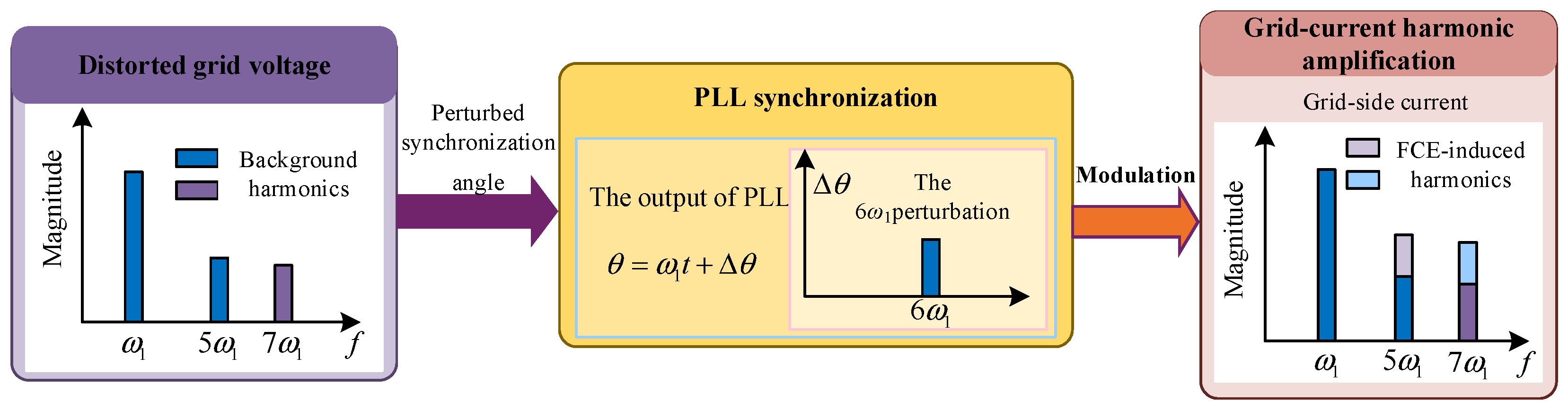
Under distorted grid conditions, PLL-induced frequency coupling can significantly influence the output current characteristics of GFLIs. In particular, when perturbations are embedded in the estimated synchronization angle, their propagation through the Park transformation leads to a deviation in the fundamental current spectrum. The multiplicative interaction between the phase perturbation and the fundamental current gives rise to frequency coupling, thereby dispersing the energy originally located at the fundamental frequency (ω1) to other spectral components.
When the synchronization angle contains a 6ω1 perturbation, modulation effects give rise to harmonic components at 5ω1 and 7ω1 in the current. Likewise, a 12ω1 perturbation leads to the emergence of components at 11ω1 and 13ω1. These observations indicate that angle ripples introduced by the PLL act through a modulation mechanism to redistribute the fundamental current energy toward neighboring harmonic frequencies, thereby generating additional harmonic sources at the output of the grid-following inverter. The harmonic amplification process of the grid current under PLL-induced frequency coupling is illustrated in Figure 1.
Under the FCE of the PLL, the expression of grid-connected current ig can be expressed as
i g = i g ∗ + i 5 , grid + i 7 , grid ︸ induced   by   grid   background   harmonics + i 5 , FCE + i 7 , FCE ︸ induced   by   FCE   of   the   PLL
where i g ∗ denotes the grid-side current reference.
Ultimately, the interaction between grid-connected nonlinear loads and the inverter’s equivalent impedance introduces initial current harmonics. Driven by the frequency coupling mechanism inherent to the PLL, these baseline distortions spawn secondary cross-coupled current components. This cascade progressively amplifies the harmonic components of the injected grid current, severely compromising output power quality. Under extreme scenarios, such interactions risk triggering system-level harmonic resonance, thereby jeopardizing the global operational stability of the GFLI.

2.2. Stability Analysis Considering Impact of FCEs

Evaluating the robustness implications of FCE on GFLIs initially requires formulating an output impedance model that captures the frequency coupling dynamics of the PLL. In LCL-filtered systems, grid voltage distortions predominantly circulate via the grid-side inductor and capacitor (L2-C) pathway [29]. Consequently, inverter-side current feedback fails to adequately mitigate grid-injected harmonics, necessitating supplementary sensors for harmonic extraction. Moreover, the current oscillations stemming from grid distortions and PLL-induced frequency coupling are generally localized within the low- to mid-frequency spectrum, so it is methodologically sound to reduce the LCL structure to a simplified L-type filter for subsequent impedance formulation and stability evaluation.
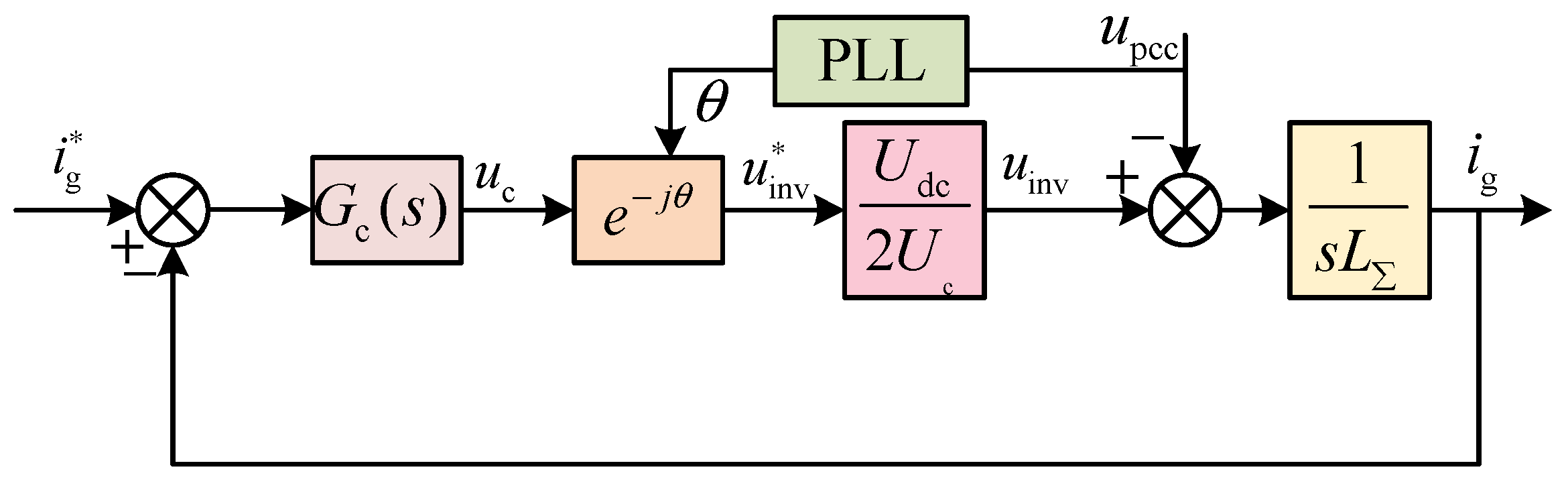
Based on the foregoing analysis, a grid current feedback control scheme is adopted, and the equivalent control structure of the three-phase GFLI is illustrated in Figure 2:
where Gc(s) denotes the current controller. The variable θ corresponds to the grid phase angle estimated by the PLL, uc is the control voltage, and the ratio Udc/Uc defines the PWM modulation gain kPWM. Moreover, L∑ stands for the aggregated filter inductance.
The parameters of the studied GFLI are listed in Table 1.
The small-signal impedance model is established around the steady-state operating point, which is suitable for evaluating the onset of harmonic instability and stability margins of grid-connected converters. According to Figure 2, the relationships between the PCC disturbance voltage and the resulting disturbance current as well as the coupling current can be derived. These relationships are characterized by the self-impedance Zsp(s) and the coupling impedance Zcp(s) are provided [19]:
Z sp ( s ) = s L ∑ + k PWM G c s − j ω 0 1 − 0.5 k PWM T PLL ( s − j ω 0 ) I d q r G c s − j ω 0 + d d q
Z cp ( s ) = ( j 2 ω 0 − s ) L ∑ + k PWM G c j ω 0 − s 0.5 k PWM T PLL ( j ω 0 − s ) I d q r G c j ω 0 − s + d d q
where TPLL(s) denotes the transfer function of the PLL.
The output impedance model of the GFLI accounting for the frequency coupling dynamics is formulated as follows:
Z inv ( s ) = [ Z sp ( s ) Z sp ∗ j 2 ω 0 − s Z cp j 2 ω 0 − s Z cp ∗ s + Z g ∗ j 2 ω 0 − s Z sp ( s ) Z cp j 2 ω 0 − s Z cp ∗ s ] /       [ Z sp ∗ j 2 ω 0 − s Z cp j 2 ω 0 − s Z cp ∗ s + Z cp j 2 ω 0 − s Z cp ∗ s Z g ∗ j 2 ω 0 − s −       Z sp ( s ) Z sp ∗ j 2 ω 0 − s Z g ∗ j 2 ω 0 − s ]
The equivalent output impedance models of the GFLI, excluding and incorporating the PLL frequency coupling dynamics, are formulated in (9) and (11), respectively. As revealed in (11), Zinv(s) exhibits an intrinsic coupling with the grid impedance, alongside its dependency on Zsp(s) and Zcp(s).
The subsequent analysis explores how PLL frequency coupling dictates GFLI stability in weak grids.
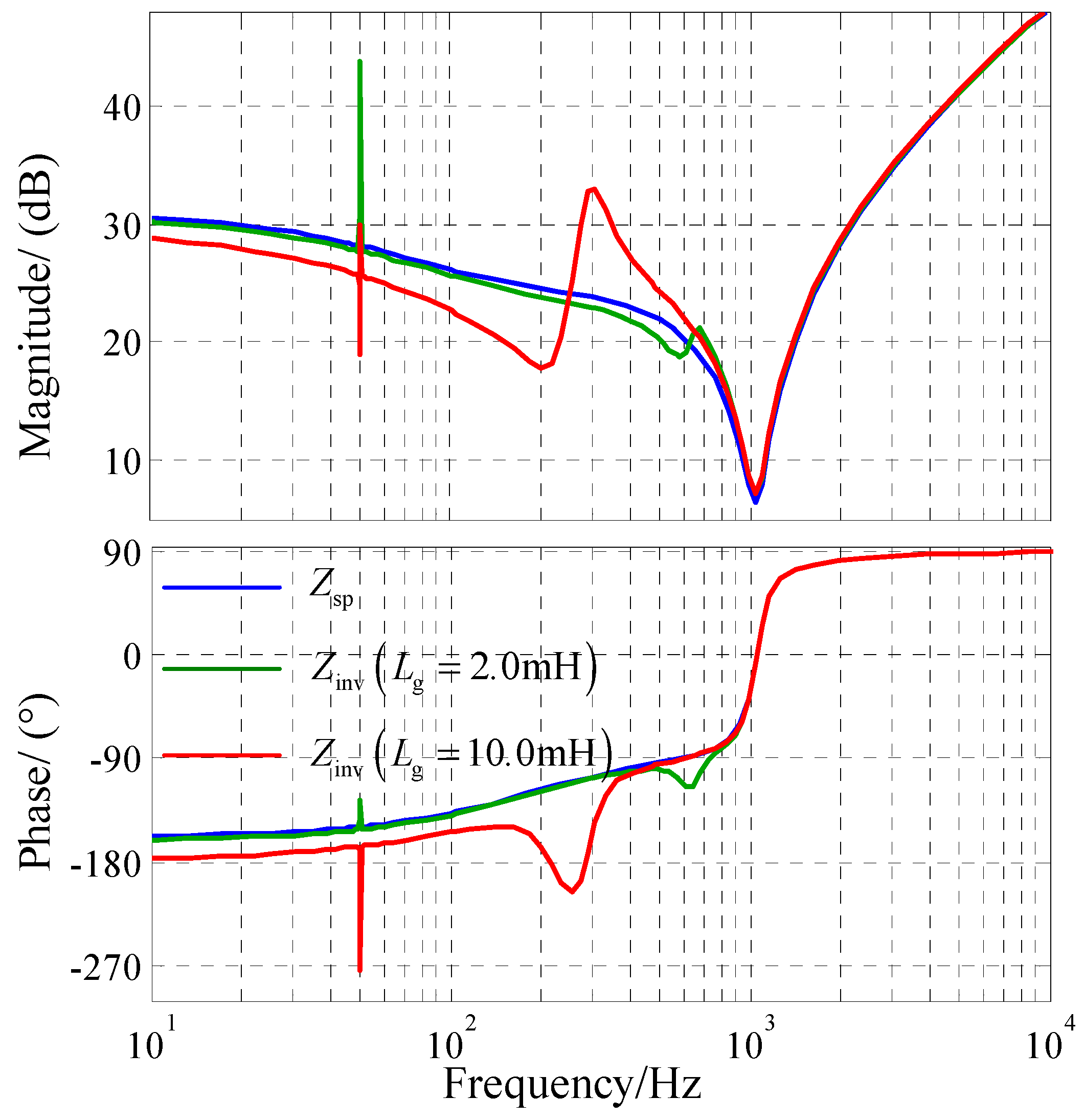
Figure 3 delineates the Bode plots of Zsp(s) and Zinv(s) under varying grid impedance levels. The frequency responses reveal that the PLL coupling mechanism broadens the negative-impedance region of the GFLI within the low and intermediate frequency bands and this negative-impedance span progressively widens as the grid impedance increases. This observation confirms that an elevated grid impedance inherently amplifies its mutual coupling with Zinv(s), severely precipitating the destabilization of the grid-following system:
Moreover, background grid distortions stemming from nonlinear loads naturally imprint their respective harmonic frequencies onto the grid-injected current. Compounding this issue, the PLL frequency coupling mechanism spawns additional cross-coupled current harmonics at 2ω0-ωh, further deteriorating the power quality of the GFLI. Therefore, mitigating frequency coupling through improved PLL design is of critical importance for enhancing system performance.

3. Mitigation Strategies for PLL-Induced FCE

3.1. Modified PLL and GFLI Impedance Reshape

According to [30], the extent of frequency coupling is dictated by the relative magnitude of the coupling admittance to the self-admittance. A larger coupling admittance implies stronger frequency dynamics, rendering standard SISO admittance models inaccurate for GFLIs. That is, the amplification of this coupling admittance aggravates system instability driven by PLL-induced FCE. Therefore, structurally modifying the PLL presents an effective strategy to enhance the stability of the GFLI.
The equivalent transformation of (11) can be obtained
Z inv ( s ) = 1 + Z g ∗ j 2 ω 0 − s Y sp ∗ j 2 ω 0 − s Y sp ( s ) + Y sp ( s ) Z g ∗ j 2 ω 0 − s Y sp ∗ j 2 ω 0 − s − Y cp j 2 ω 0 − s Y cp ∗ s Z g ∗ j 2 ω 0 − s
where Yx(*) denotes the admittance, which is the reciprocal of Zx(*).
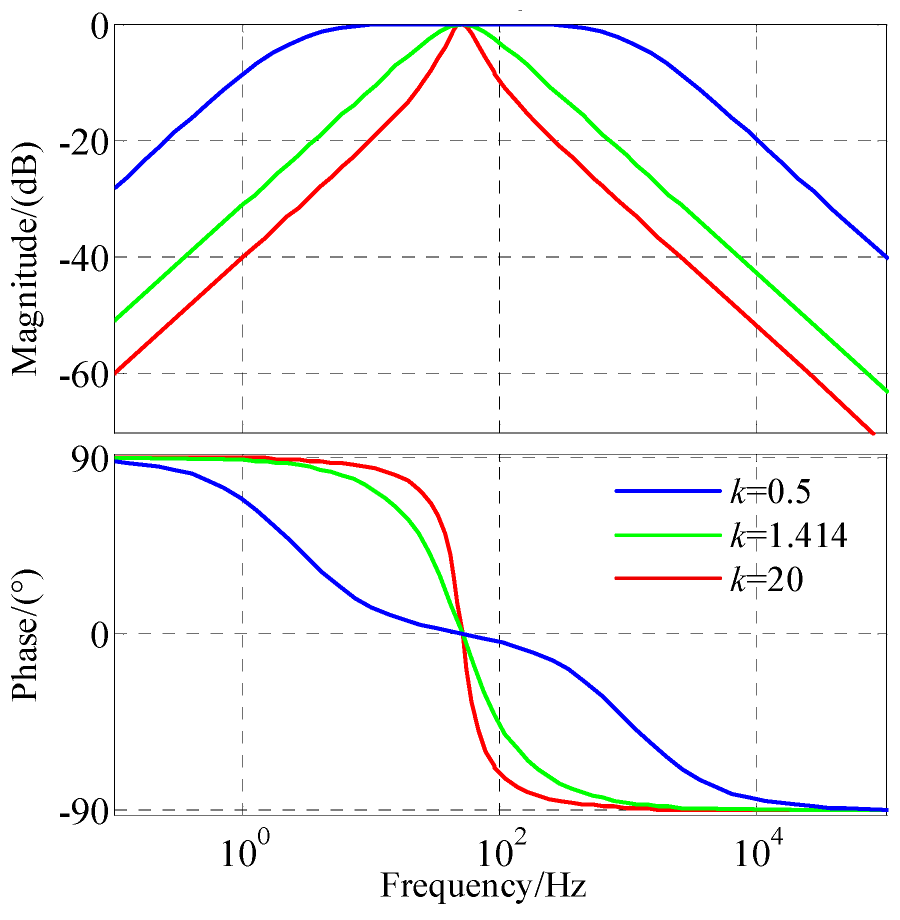
From (11) and Figure 3, it is evident that, in the presence of PLL-induced frequency coupling, the negative impedance region of the GFLI output impedance progressively enlarges with increasing grid impedance, mainly due to the incorporation of coupling admittance (impedance). In addition, (10) suggests that reducing the magnitude of TPLL(s) diminishes its interaction with the coupling admittance, thereby weakening the influence of FCE on the low-frequency impedance characteristics of the GFLI. Prior studies [7,19] have also demonstrated that the SOGI unit embedded in SOGI-PLL can effectively attenuate coupling components within the loop, contributing to the suppression of FCE. The coefficient k determines the damping characteristic and bandwidth of the SOGI-based orthogonal signal generator, thereby affecting the harmonic attenuation capability and dynamic behavior of the PLL. As shown in Figure 4, a reduced k value enhances the filtering performance of the SOGI-PLL, attenuates the PLL-induced FCE, and improves the stability robustness of the grid-connected system. However, an excessively small k narrows the effective bandwidth and slows down the transient response. Therefore, k = 1.414 is commonly adopted in SOGI-PLL designs to achieve a compromise between disturbance rejection capability and dynamic performance, while k = 20 is considered as a high-bandwidth condition to evaluate the robustness of the proposed ESOGI-PLL [31].
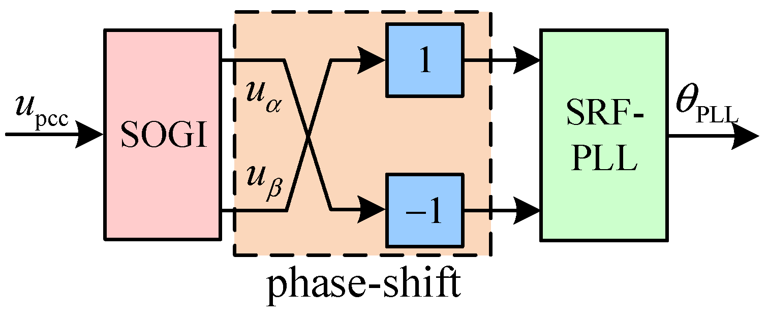
To circumvent the k-constrained phase compensation limits of the conventional SOGI-PLL, an ESOGI-PLL with phase-shift modification is developed to mitigate PLL-induced frequency coupling and improve the stability margin of GFLIs. It should be noted that the proposed ESOGI-PLL is a linear phase-compensation-based synchronization method rather than an adaptive or nonlinear control strategy. As shown in Figure 5, a fixed phase-lead compensation unit is introduced into the conventional SOGI-PLL structure by applying a 90° phase shift to the orthogonal outputs of the SOGI. This structural modification reshapes the phase characteristics of the synchronization loop and the impedance behavior of the GFLI, thereby mitigating the PLL-induced frequency coupling effect and improving the stability margin in the low- and medium-frequency ranges.
The transfer function of the phase-shift-based ESOGI-PLL can be expressed as
T α _ ESOGI - PLL s = k ω 0 2 s 2 + k ω 0 s + ω 0 2 ⋅ H PLL ( s ) 1 + U 1 H PLL ( s ) T β _ ESOGI - PLL s = k ω 0 s s 2 + k ω 0 s + ω 0 2 ⋅ H PLL ( s ) 1 + U 1 H PLL ( s )
By synthesizing (16) and (17), the output admittance model of the GFLI equipped with the proposed ESOGI-PLL is established as (18):
Y inv − SOGI ( s ) = Y Esp ( s ) + Y Esp ( s ) Z g ∗ j 2 ω 0 − s Y Esp ∗ j 2 ω 0 − s − Y Ecp j 2 ω 0 − s Y Ecp ∗ s Z g ∗ j 2 ω 0 − s 1 + Z g ∗ j 2 ω 0 − s Y Esp ∗ j 2 ω 0 − s
where YEsp(s) and YEcp(s) denote the ESOGI-PLL-governed self-admittance and cross-coupling admittance, which are detailed in (15) and (16), respectively:
Y Esp ( s ) = 1 − 0.5 k PWM T ESOGI - PLL ( s − j ω 0 ) I d q r G c s − j ω 0 + d d q s L ∑ + k PWM G c s − j ω 0
Y Ecp ( s ) = 0.5 k PWM T ESOGI - PLL ( j ω 0 − s ) I d q r G c j ω 0 − s + d d q ( j 2 ω 0 − s ) L ∑ + k PWM G c j ω 0 − s

3.2. Performance Evaluation of the ESOGI-PLL

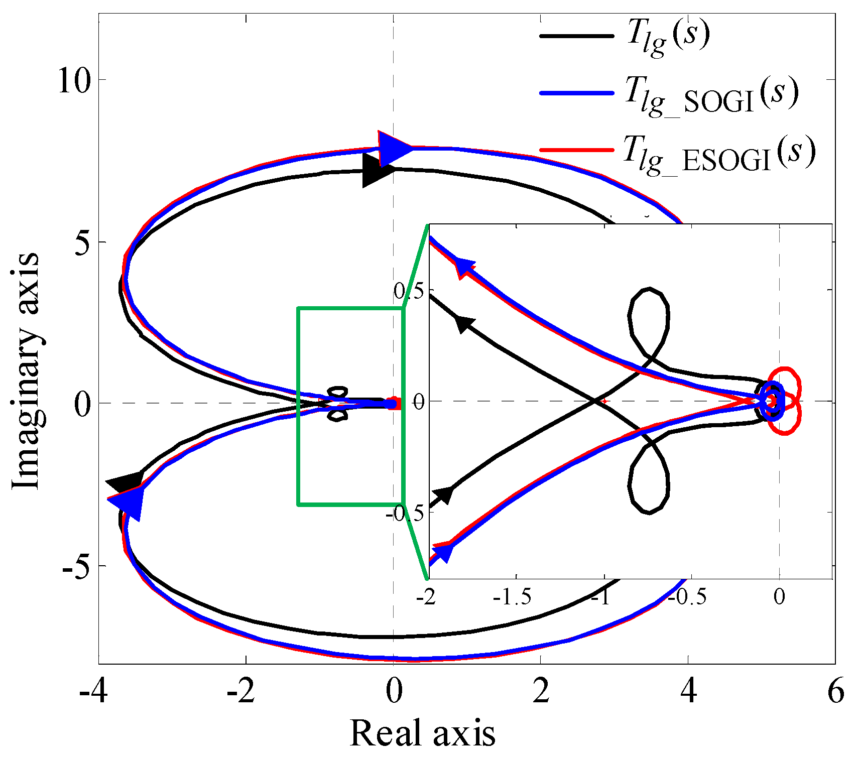
To validate the stabilizing efficacy of the improved SOGI-PLL on the GFLI system, Nyquist stability criteria are evaluated under different PLL bandwidth conditions. Specifically, Figure 6 presents the Nyquist diagrams of the open-loop transfer functions Tlg(s), Tlg_SOGI(s), and Tlg_ESOGI(s), configured with Lg = 10.0 mH and k = 1.414. The corresponding analytical expressions for these transfer functions are formulated as:
T l g s = Y inv s Z g s T l g _ SOGI s = Y inv _ SOGI s Z g s T l g _ ESOGI s = Y inv _ ESOGI s Z g s
where Yinv(s), Yinv_SOGI(s), Yinv_ESOGI(s) denote the output admittances of the three-phase GFLI when utilizing the SRF-PLL, SOGI-PLL, and the phase-shifted ESOGI-PLL, respectively.
From Figure 6, it can be observed that for Lg = 10.0 mH, the Nyquist trajectory of Tlg(s) under the SRF-PLL encloses the critical point (−1, j0), indicating that the GFLI becomes unstable under PLL-induced frequency coupling. By comparison, the trajectories of Tlg_SOGI(s) and Tlg_ESOGI(s) do not encircle this critical point, implying that the SOGI-based schemes can alleviate the coupling effect to some extent. For smaller values of k, both SOGI-PLL and ESOGI-PLL are capable of maintaining stability; however, the dynamic response of the GFLI is degraded under these conditions.
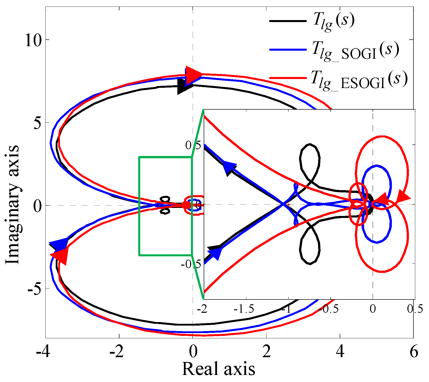
When the bandwidth coefficient k is elevated to 20, the corresponding open-loop Nyquist trajectories for Tlg(s), Tlg_SOGI(s) and Tlg_ESOGI(s) at Lg = 10.0 mH are depicted in Figure 7. (In this study, k = 1.414 is selected as a typical PLL parameter, whereas k = 20 is used to represent a high-bandwidth operating condition. A larger bandwidth coefficient leads to a faster synchronization response. Therefore, the case of k = 20 is considered to examine whether the proposed ESOGI-PLL can retain stable operation while providing improved dynamic performance. Theoretical analysis and simulation results confirm its effectiveness under such conditions.) Notably, the contour of Tlg_SOGI(s) now encircles the critical point (−1, j0), indicating that the conventional SOGI-PLL drives the GFLI into instability at higher k values. In contrast, the Tlg_ESOGI(s) locus successfully bypasses this coordinate. This robustness is attributed to the low-to-mid-frequency phase compensation embedded within the ESOGI-PLL architecture. Consequently, the proposed structure not only secures the stability of the inverter-grid system but also facilitates further improvements in both transient response agility and harmonic mitigation.

4. Results

To corroborate the theoretical derivations and validate the proposed PLL design, a comprehensive simulation model of the GFLI system based on MATLAB 2012/Simulink is constructed. The simulation is performed using a fixed-step ode2 (Heun) solver, with the fundamental step size automatically determined according to the sampling configuration of the implemented control system.

4.1. Performance Evaluation of the Proposed ESOGI-PLL

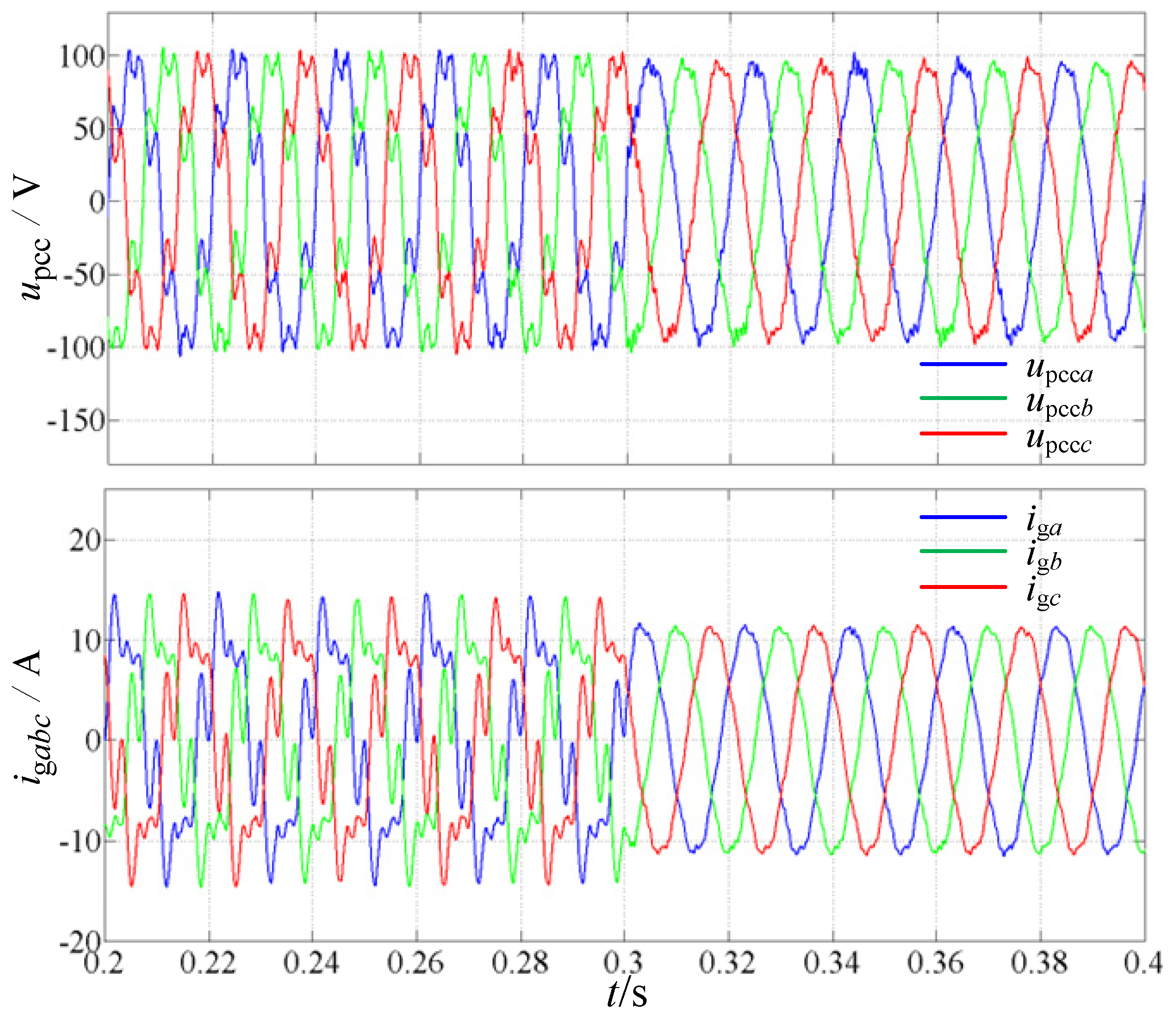
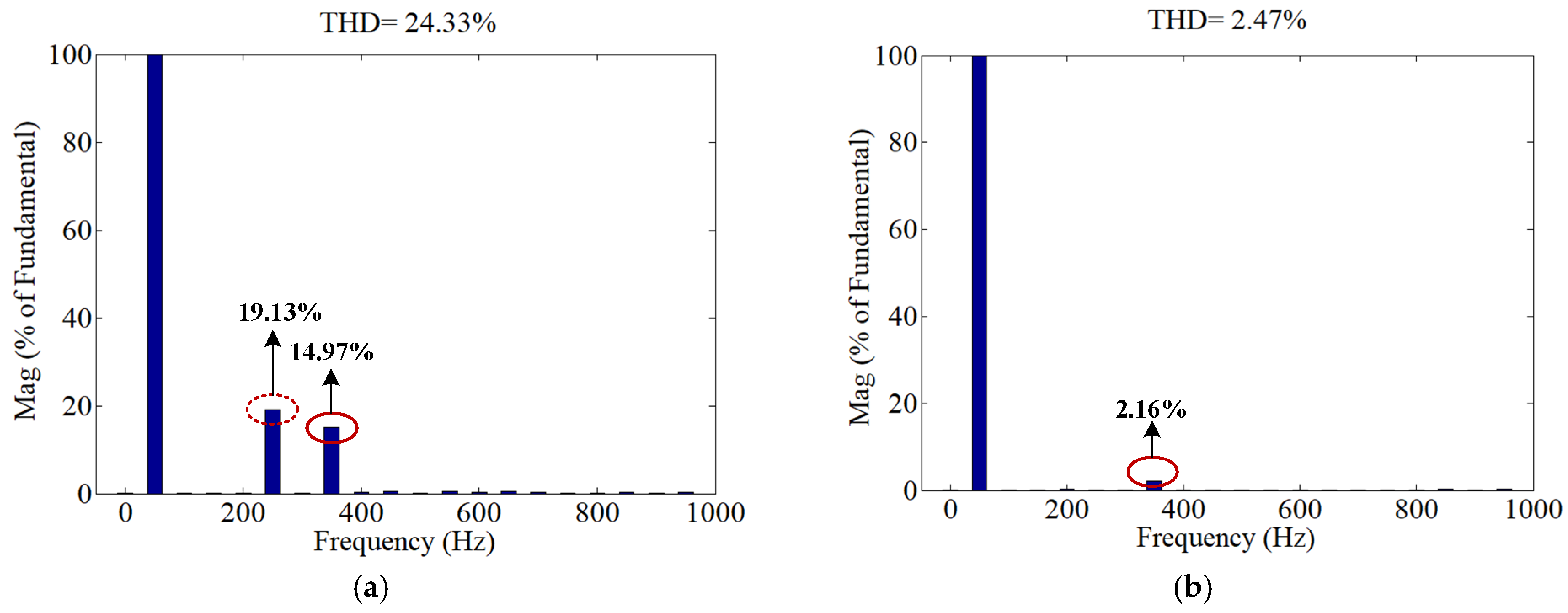
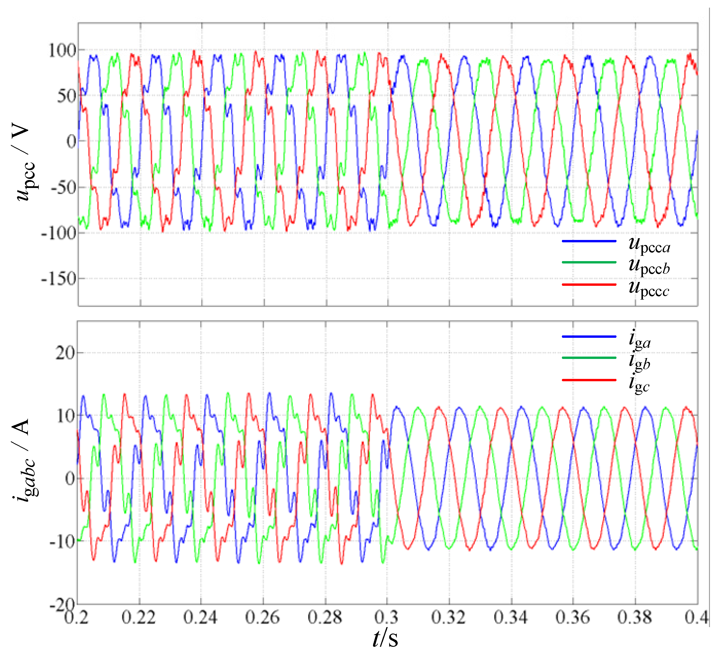
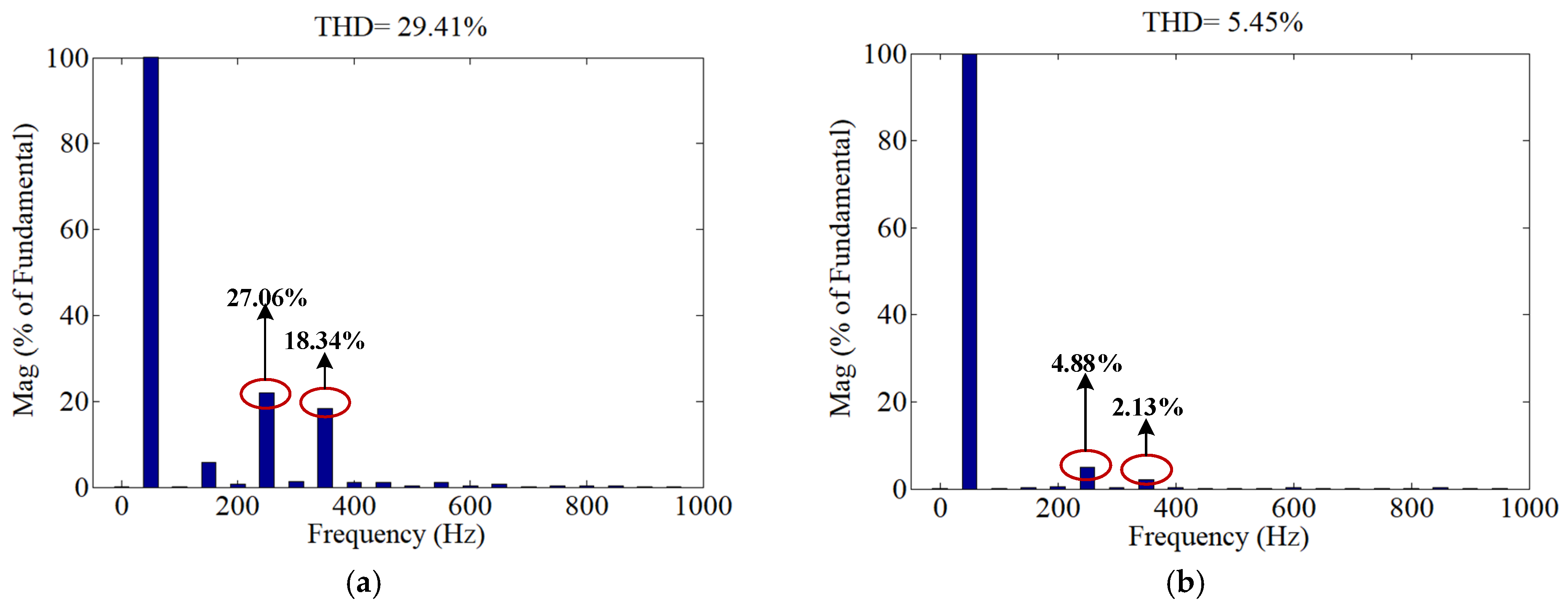
Initially, the frequency coupling behavior of the PLL is evaluated. Under a stable operating scenario with Lg = 2.0 mH, a 3% 7th-harmonic voltage is injected at the PCC to emulate background grid distortion. Subsequently, the control scheme transitions from the SRF-PLL to the proposed ESOGI-PLL at t = 0.3 s. Figure 8 depicts the transient waveforms of the grid-injected current ig during this switch-over under the harmonically polluted PCC voltage. The corresponding spectral evaluations of the current before and after this transition are detailed in Figure 9.
As illustrated in Figure 9, pronounced spectral components are observed at 250 Hz and 350 Hz in the grid current. This indicates that, when a 7th-order harmonic is present in the PCC voltage, the FCE introduces not only the original harmonic component but also an additional coupled component at (2ω0-ω1). These results demonstrate that background grid harmonics, once processed through the PLL, give rise to new harmonic components at the inverter output, thereby increasing the distortion level of the injected current and deteriorating the output power quality of the GFLI. In severe cases, the harmonic distortion may deteriorate the power quality and even trigger protective actions, potentially resulting in inverter disconnection.
Furthermore, the harmonic component at 250 Hz is markedly reduced when the ESOGI-PLL is adopted. This observation indicates that the proposed ESOGI-PLL effectively attenuates frequency-coupled components, thereby suppressing the associated current harmonics and enhancing the output power quality of the grid-following inverter.
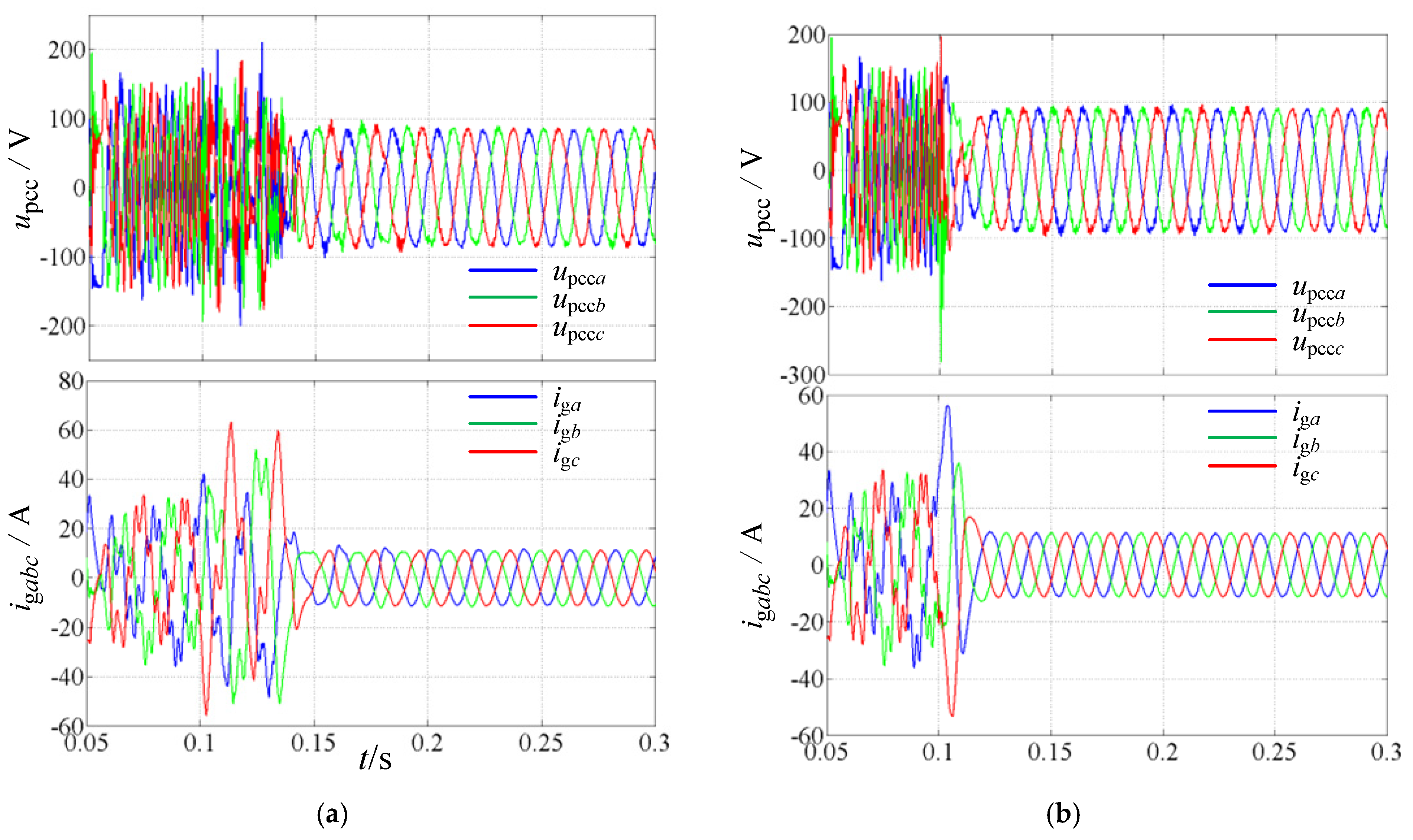
As the grid impedance is further escalated to 6 mH, Figure 10 illustrates the waveforms of upcc and igabc during the transition from the SRF-PLL to the ESOGI-PLL with Lg = 6.0 mH (SCR = 4.8).
Owing to the reduced SCR associated with the large grid impedance, the inverter operating with the SRF-PLL becomes unstable. By contrast, the proposed ESOGI-PLL successfully suppresses the instability and restores the system to a stable operating state. The results confirm that the proposed PLL structure improves the robustness of the grid-connected inverter against weak-grid conditions and enlarges the stable operating range under high grid impedance.
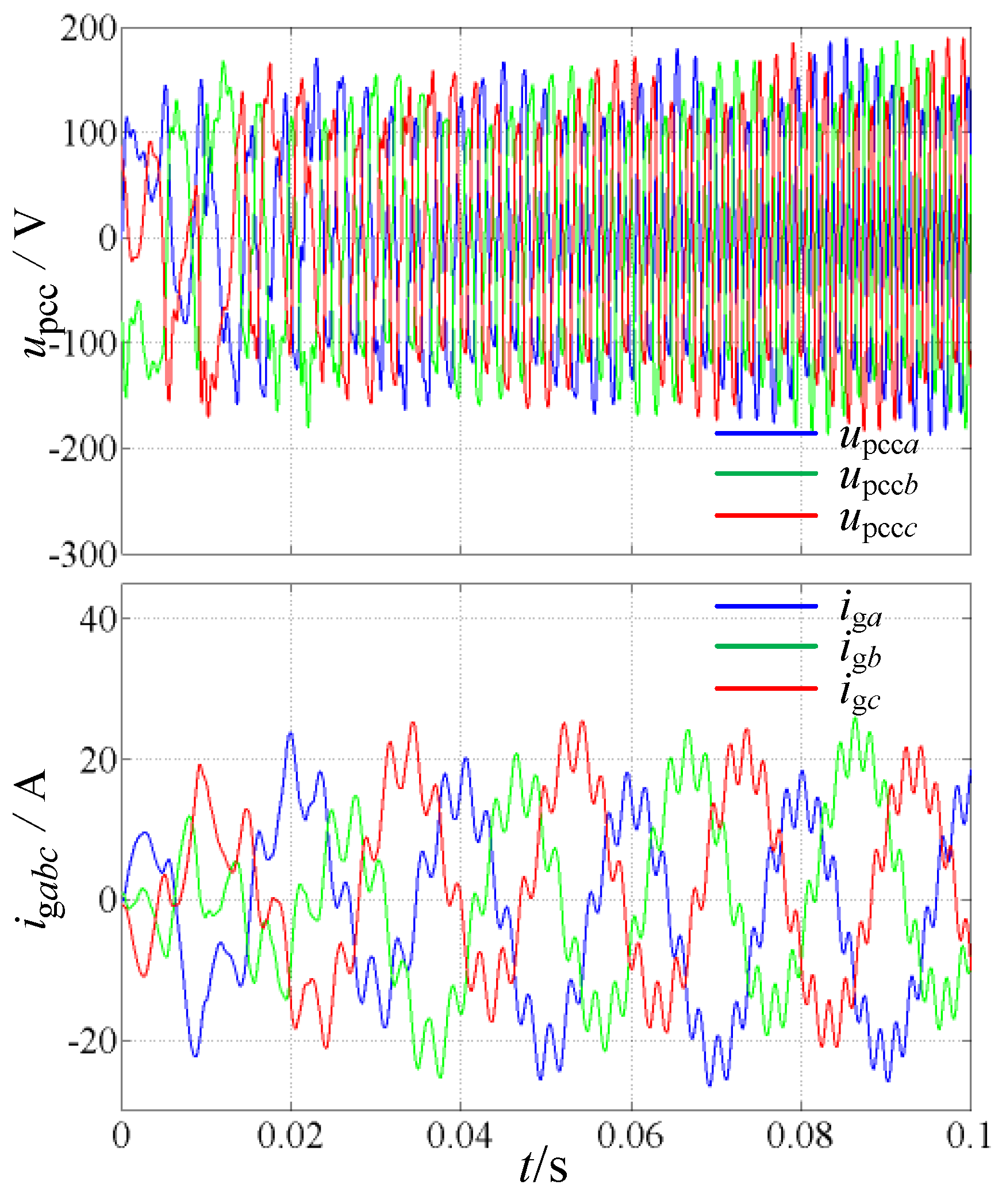
To further evaluate the performance of ESOGI-PLL under weaker grid conditions, the grid impedance is increased to 10.0 mH. Figure 11 presents the simulated waveforms of the PCC voltage upcc and the grid current ig under a conventional PLL. Under this condition, pronounced low-frequency oscillations appear in the grid current, indicating that the GFLI operates in an unstable regime.
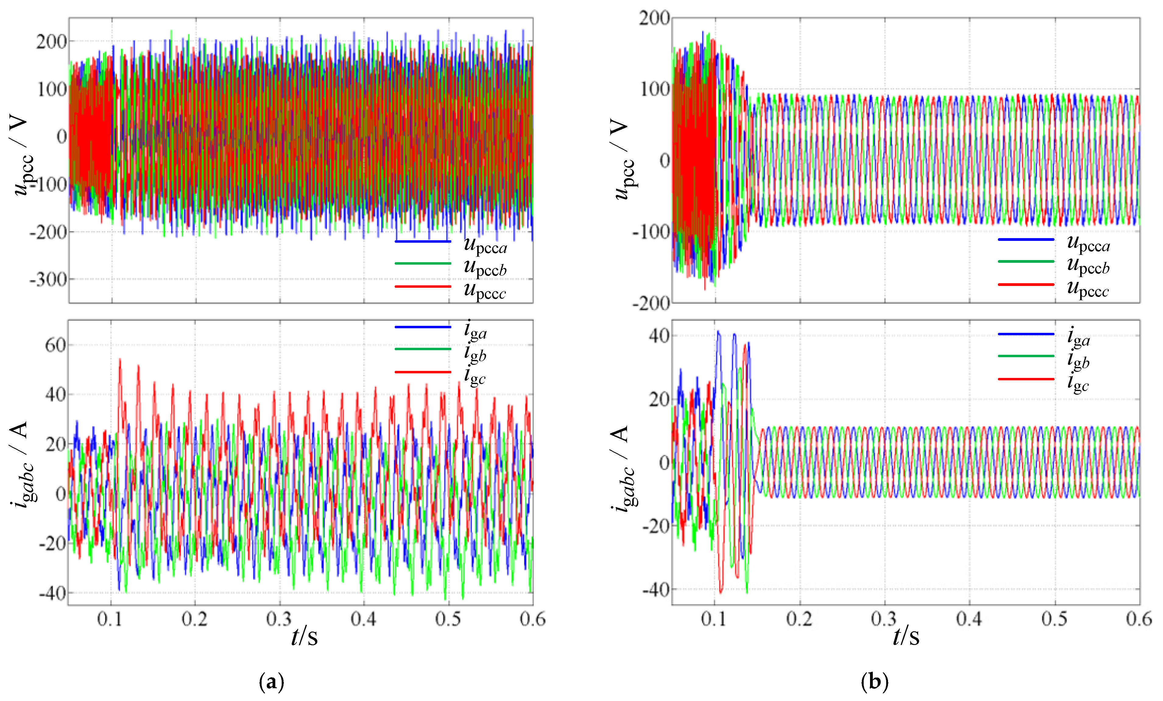
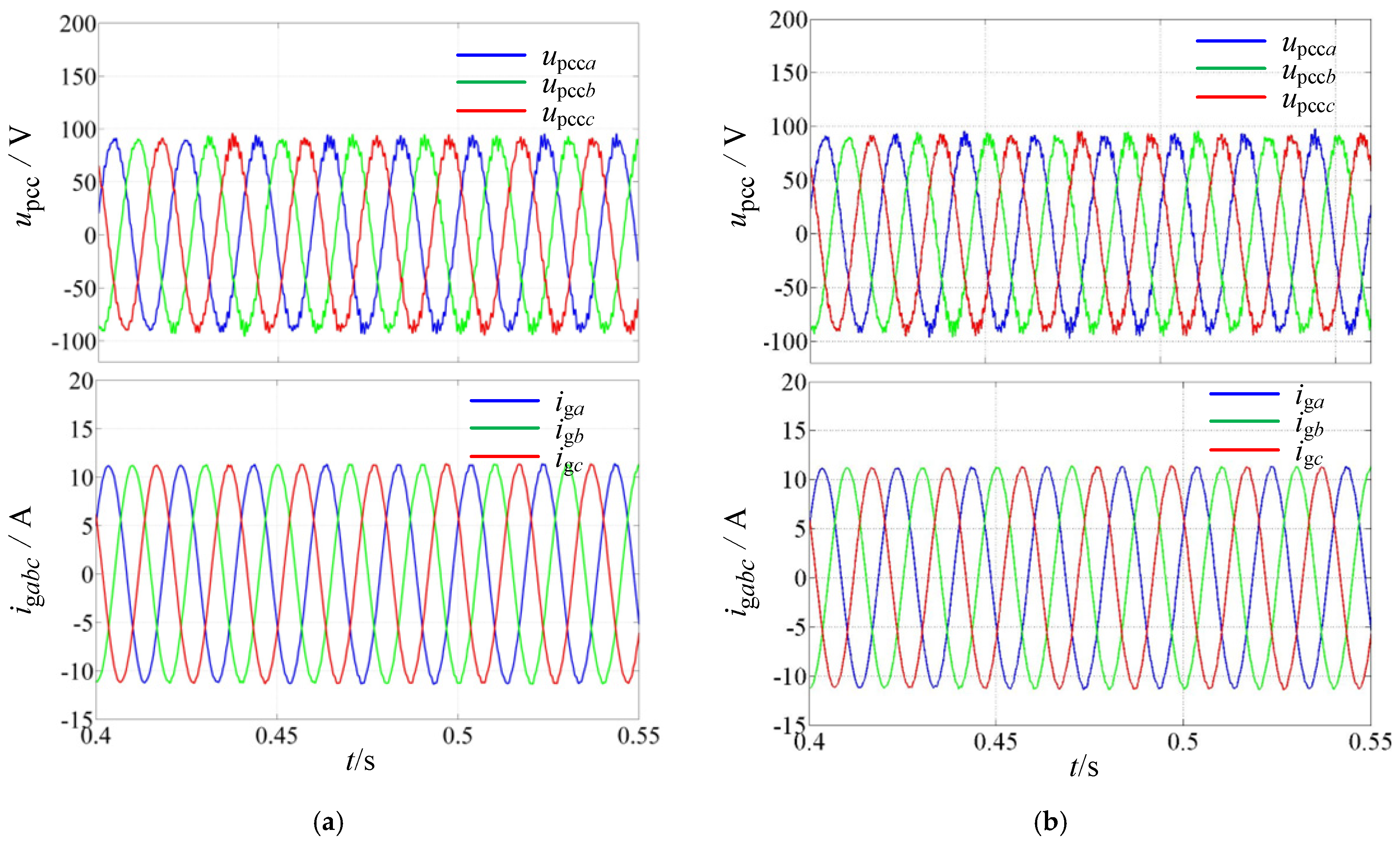
To address the instability of SRF-PLL-based inverter systems under weak grid conditions, two configurations based on SOGI-PLL and ESOGI-PLL are implemented. By exploiting the harmonic attenuation capability of the second-order generalized integrator and its phase-shift-enhanced counterpart, the PLL-induced FCE is mitigated, thereby improving the stability of grid-following inverters in weak grids. Figure 12 illustrates the transient responses at t = 0.1 s for Lg = 10.0 mH and k = 1.414. Specifically, Figure 12a corresponds to the case with SOGI-PLL, while Figure 12b presents the results obtained with ESOGI-PLL.
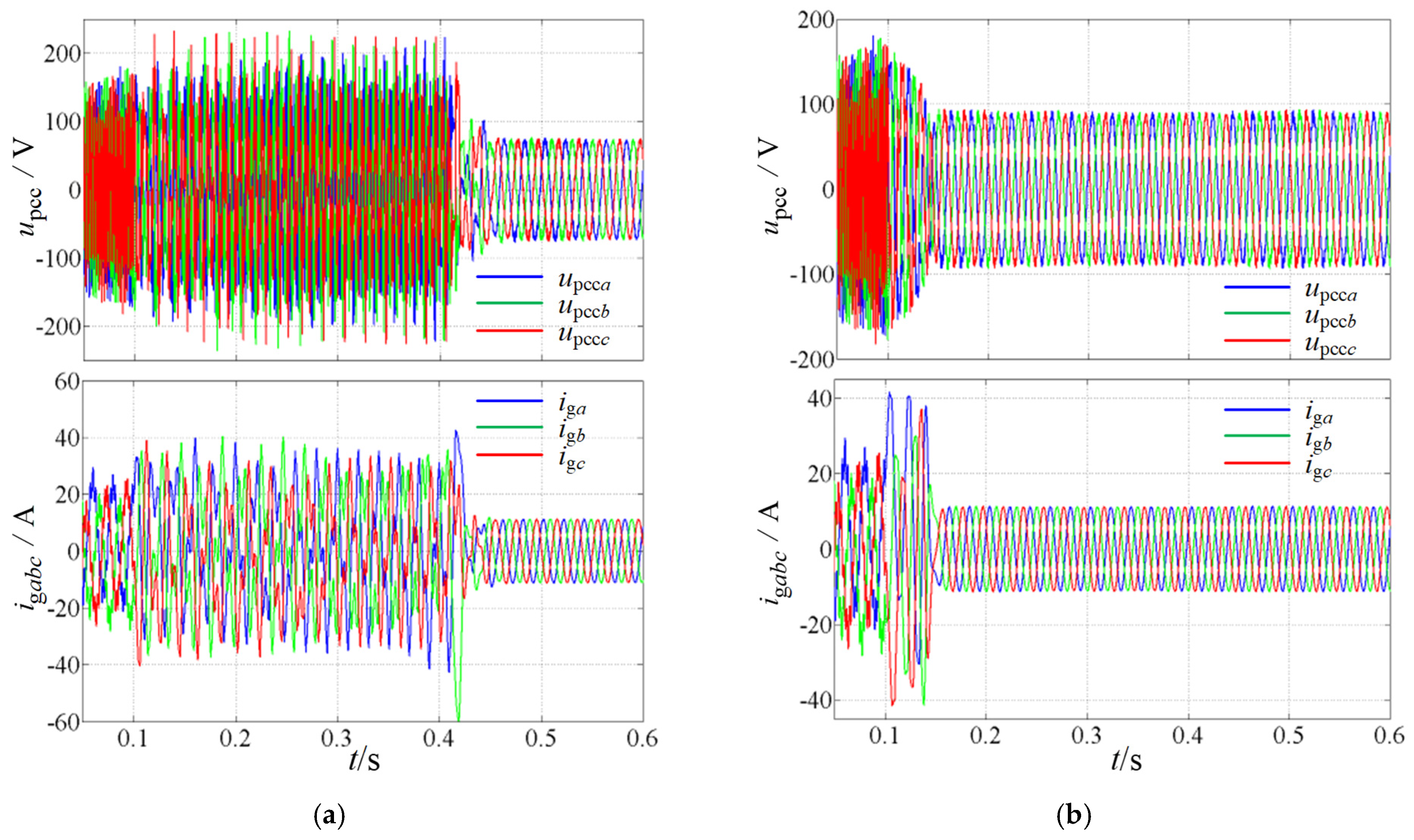
The bandwidth coefficient k is used to characterize the dynamic response speed of the PLL. A larger value of k results in a wider bandwidth and faster synchronization dynamics. Then, the bandwidth coefficient is increased to k = 20; the corresponding transient waveforms are shown in Figure 13. Figure 13a depicts the results for the SOGI-PLL, whereas Figure 13b shows those for the ESOGI-PLL under the same conditions.
As shown in Figure 12, the GFLI remains stable, indicating that both SOGI-PLL and ESOGI-PLL can effectively suppress PLL-induced frequency coupling and enhance system robustness when a small k is adopted. In contrast, Figure 13 reveals that, at larger k, the SOGI-PLL fails to prevent instability associated with PLL-induced coupling effects. By comparison, the ESOGI-PLL, benefiting from phase compensation, improves the negative impedance characteristics of the GFLI in the low- and medium-frequency ranges, thereby maintaining stable operation under weak grid conditions. Overall, these results demonstrate that the ESOGI-PLL provides a wider stability range, confirming the effectiveness of the proposed approach.
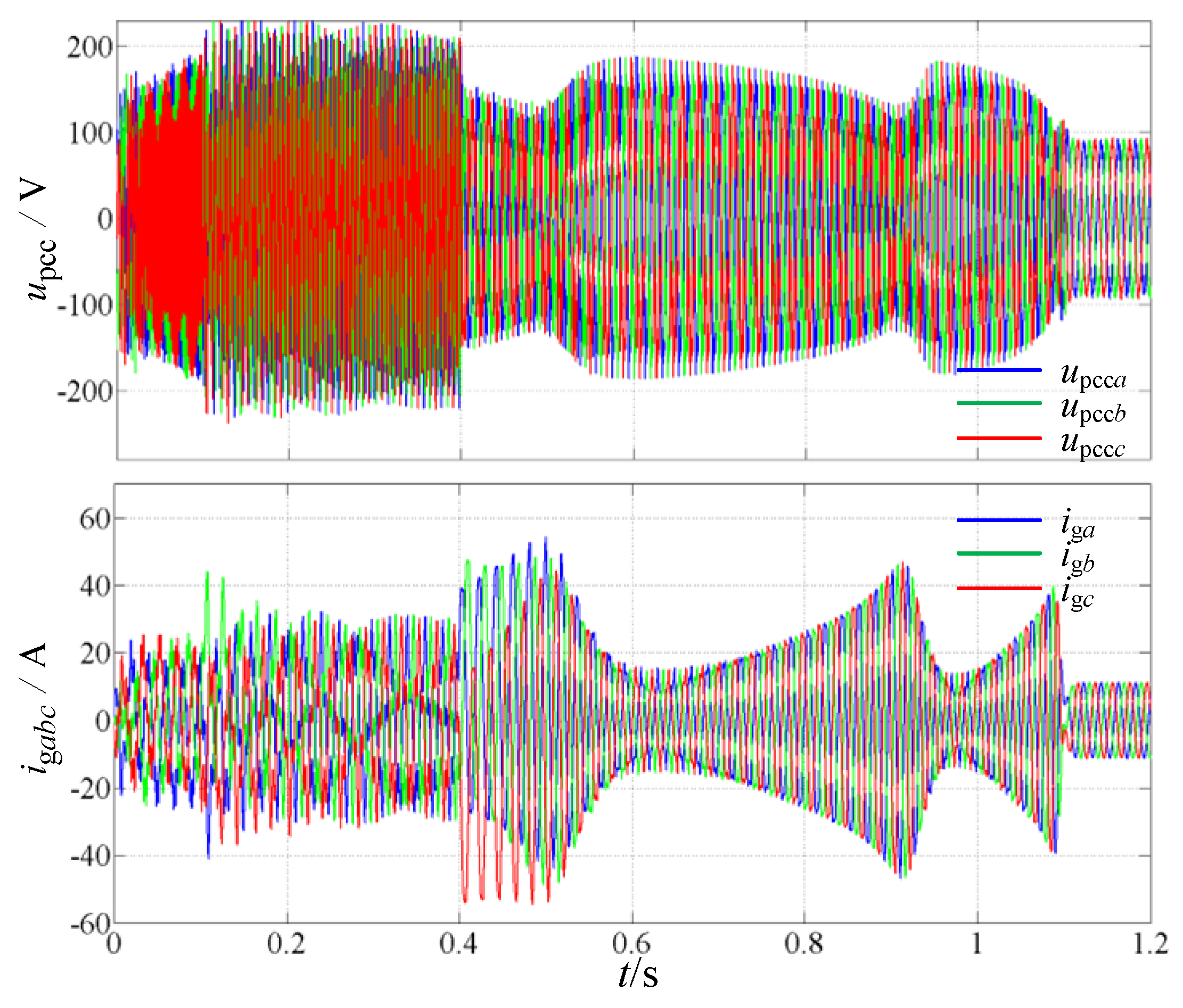
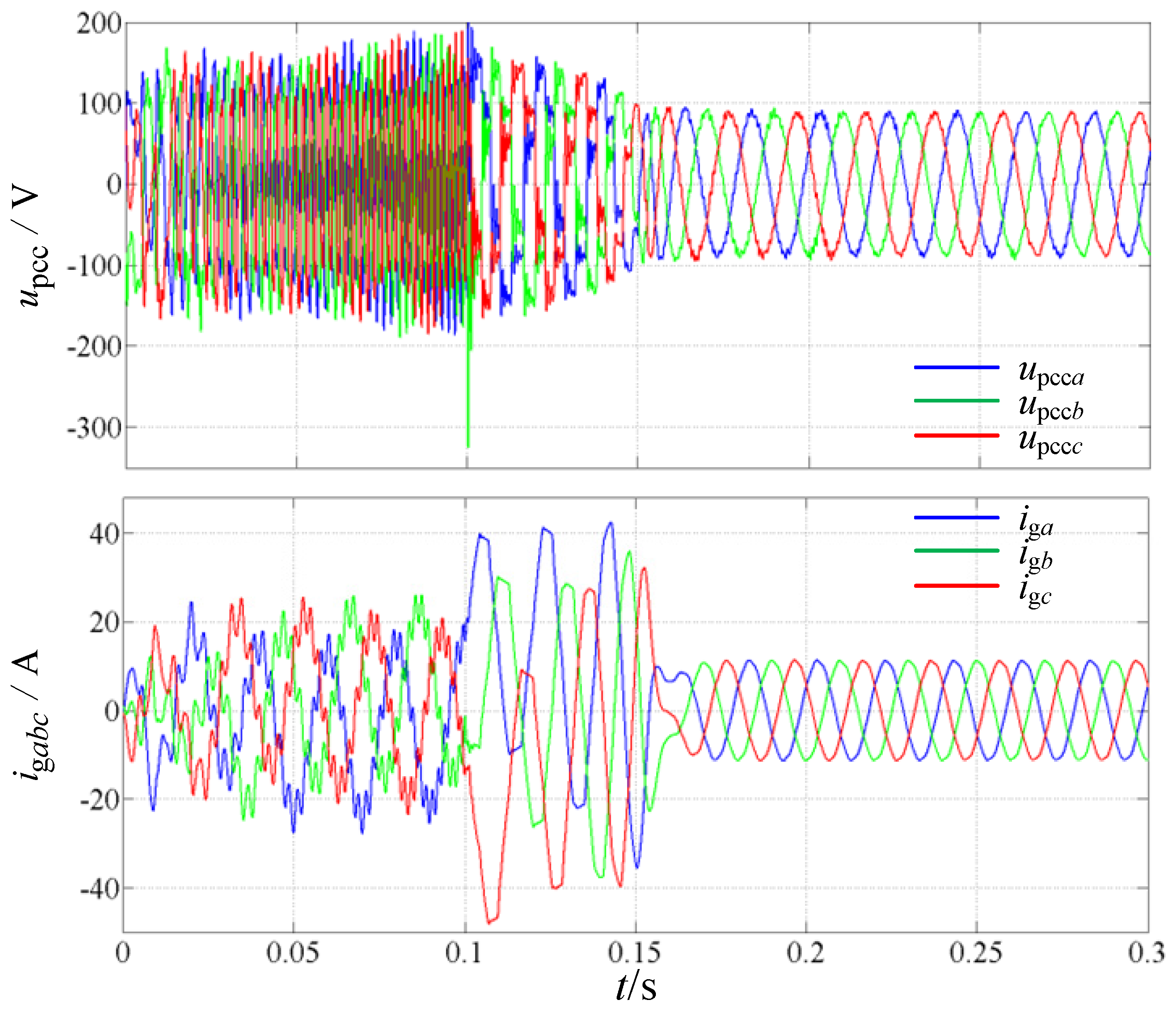
Figure 14 compares the dynamic performance of the SRF-PLL, a second-order low-pass-filter-based PLL reported in [19], and the proposed ESOGI-PLL under a weak-grid condition (Lg = 10 mH). When the PLL is switched from the SRF-PLL to the low-pass-filter-based PLL at t = 0.1 s, the oscillatory behavior of the inverter is not fundamentally eliminated, indicating that the frequency-coupling effect remains significant. In contrast, when the proposed ESOGI-PLL is activated at t = 0.4 s, the upcc and t ig quickly converge to stable waveforms. The results reveal that, although the low-pass-filter-based PLL can provide partial improvement, its ability to mitigate PLL-induced frequency coupling is still insufficient under severe weak-grid conditions. The proposed ESOGI-PLL achieves a more effective suppression of the coupling effect and provides a substantially improved stability margin.
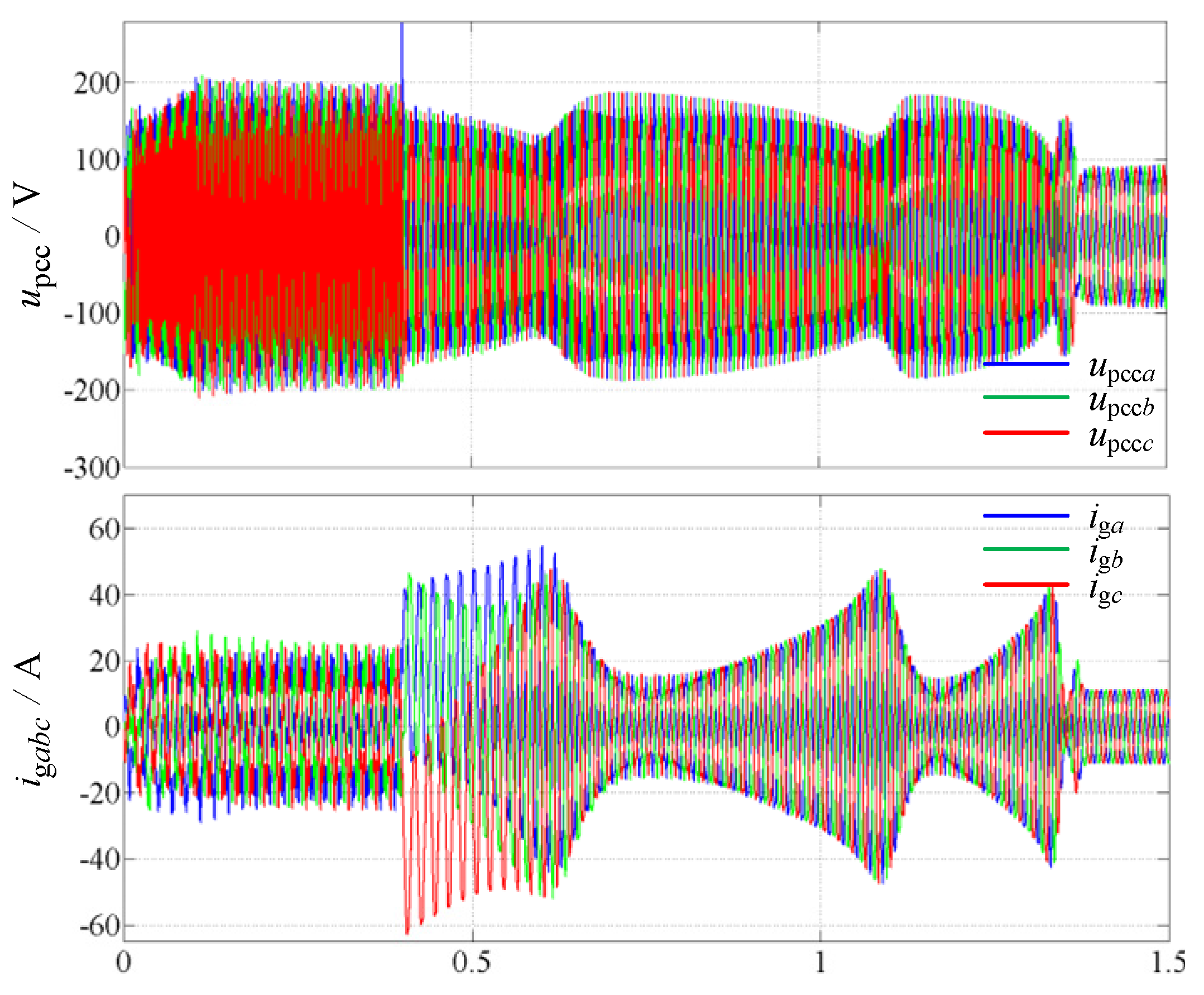
A further comparison with the BPF-based PLL is provided in Figure 15. Under the same grid condition (Lg = 10 mH), the synchronization structure is changed from SRF-PLL to BPF-PLL at t = 0.1 s and subsequently to the proposed ESOGI-PLL at t = 0.4 s. The BPF-PLL reduces the oscillatory components to some extent owing to its harmonic attenuation capability; however, the inverter still suffers from instability in the extremely weak-grid environment. This phenomenon is mainly related to the phase characteristics introduced by the filtering process. Although harmonic components in the synchronization loop can be attenuated, the additional phase delay may deteriorate the output impedance phase of the inverter and weaken the damping effect required to counteract FCE-induced instability. After adopting the proposed ESOGI-PLL, the oscillatory components are gradually eliminated and the grid current returns to a stable state, verifying the effectiveness of the proposed phase-compensation-based synchronization strategy.

4.2. Robustness Verification

Robustness was further assessed by considering both parameter variations and operating-condition disturbances.
To further evaluate the effectiveness of the proposed ESOGI-PLL under more practical distorted grid conditions, multiple background harmonics are considered. Figure 16 and Figure 17 present the transient responses of the upcc and ig, as well as the corresponding harmonic spectra, when 5th- and 7th-order harmonics are simultaneously introduced into the PCC voltage under Lg = 2.0 mH. Compared with the conventional SRF-PLL, the proposed ESOGI-PLL effectively suppresses the current distortion induced by PLL-FCE under the multi-harmonic disturbance condition, demonstrating its capability to mitigate harmonic propagation through the synchronization loop.
Furthermore, the grid impedance is increased from Lg = 2.0 mH to Lg = 10 mH while maintaining the same multi-harmonic voltage disturbance. As shown in Figure 18, the proposed ESOGI-PLL still maintains stable inverter operation and achieves improved current quality under this more challenging condition. These results indicate that the proposed method preserves effective frequency-coupling suppression capability under complex grid conditions.
Figure 19 presents the PCC voltage and grid current waveforms obtained when the grid-side inductance is increased and decreased under the condition of Lg = 10 mH, which are derived from independent simulation cases, rather than from an online inductance variation during a single simulation. Despite the variation in the filter parameter, the inverter operating with the proposed ESOGI-PLL maintains stable operation without noticeable deterioration in the dynamic behavior, indicating a low sensitivity to inductance deviations.
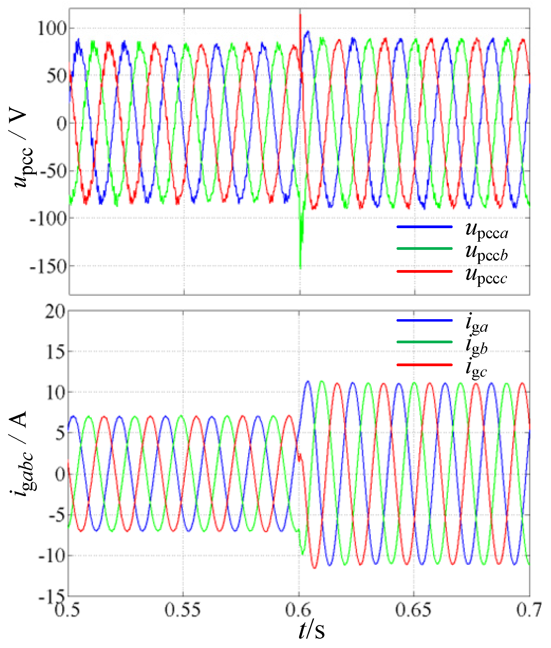
The transient behavior of the proposed ESOGI-PLL is further examined under a sudden load-current variation. As illustrated in Figure 20, the grid current is stepped from half-rated operation to full-load condition with the PLL coefficient k set to 20. Although this relatively large k value increases the synchronization bandwidth, the proposed ESOGI-PLL preserves stable operation without apparent oscillatory amplification. Following the load transition, the system restores its steady-state condition within approximately 0.005 s, indicating that the proposed phase-compensation scheme can achieve rapid dynamic response while maintaining stability under high-bandwidth settings.
The above results demonstrate that the proposed ESOGI-PLL preserves stable operation under both parameter perturbations and transient operating conditions.

5. Conclusions and Discussion

This paper investigates the influence of PLL-induced frequency coupling on the stability and output-current quality of GFLIs operating under weak-grid conditions with background harmonics. Based on disturbance analysis and impedance modeling, a phase-compensated ESOGI-PLL is developed to mitigate frequency-coupling effects. The main conclusions are summarized as follows.
The results indicate that background grid harmonics are transferred to the inverter output current through the PLL coupling pathway, which serves as a primary source of current distortion. Meanwhile, frequency coupling introduces a strong interaction between the inverter output impedance and the grid impedance. Under weak grid conditions, a pronounced phase reduction in the low- and medium-frequency ranges is observed, leading to a higher likelihood of instability. This observation complements conventional impedance-based analyses by explicitly accounting for coupling dynamics, thereby improving the reliability of stability evaluation.
The proposed enhanced SOGI-PLL incorporates a phase-lead compensation mechanism to offset the inherent phase lag of the filtering stage, achieving a balance between harmonic attenuation and dynamic bandwidth. Simulation results confirm that this approach effectively alleviates the adverse influence of frequency coupling while improving the stability margin.
In contrast to impedance reshaping and feedforward compensation schemes that rely on additional estimation mechanisms or auxiliary control paths, the proposed ESOGI-PLL mitigates the FCE through an inherent phase-compensation strategy embedded in the synchronization loop. Specifically, a fixed 90° phase shift is introduced into the SOGI-generated orthogonal component, which modifies the phase characteristics of the PLL output impedance in the low- and medium-frequency regions. This structural modification avoids additional compensation units and parameter adjustment procedures while maintaining a simple implementation framework. Moreover, only one extra multiplication operation is introduced per sampling interval compared with the conventional SOGI-PLL, whereas the number of addition operations remains unchanged, demonstrating the computational efficiency of the proposed approach for digital controller implementation. Therefore, the proposed method can be readily implemented on standard digital control platforms, providing favorable potential for practical engineering applications.

6. Limitations and Future Work

The present work evaluates the proposed ESOGI-PLL through analytical and simulation studies over a range of weak-grid conditions, operating scenarios, and filter-parameter variations, demonstrating its effectiveness in improving synchronization performance and system stability. Although the proposed method has been validated through analytical analysis and comprehensive simulation studies, experimental and hardware-in-the-loop (HIL) evaluations are still needed to further examine its real-time implementation performance and engineering applicability. Moreover, the current investigation focuses on a single grid-following inverter, while the potential interactions among multiple converter systems have not yet been considered. In addition, future studies will further extend the robustness evaluation by incorporating a wider range of grid conditions, including diverse grid-impedance characteristics, PLL bandwidths, controller configurations, voltage disturbances, and frequency variations. These aspects will be addressed in future work to further evaluate the applicability of the proposed ESOGI-PLL under more complex grid environments.

Author Contributions

Conceptualization, Y.Z. and H.P.; methodology, Y.Z. and H.P.; software, X.Z.; validation, Y.Z., H.P. and X.Z.; formal analysis, L.D. and K.Y.; investigation, Y.Z. and H.P.; resources, L.D. and K.Y.; data curation, L.D. and K.Y.; writing—original draft preparation, Y.Z.; writing—review and editing, Y.Z. and H.P.; visualization, X.Z.; supervision, H.P.; project administration, Y.Z. and H.P.; funding acquisition, H.P. All authors have read and agreed to the published version of the manuscript.

Funding

This research was funded by the National Natural Science Foundation of China, grant number 52304088.

Data Availability Statement

The original contributions presented in this study are included in the article. Further inquiries can be directed to the corresponding author.

Conflicts of Interest

Author Xiaoyu Zhang was employed by Emergency Science Research Institute, China Coal Research Institute (China). The remaining authors declare that the research was conducted in the absence of any commercial or financial relationships that could be construed as potential conflicts of interest.

Abbreviations

The following abbreviations are used in this manuscript:
PLLPhase-Locked Loop
FCEFrequency Coupling Effect
GFLIGrid-following inverter
SISOSingle Input Single Output
MIMOmulti-input multi-output
BPFband-pass filter
PCCPoint of Common Coupling
SRFSynchronous Reference Frame
PWMPulse Width Modulation
OSGOrthogonal Signal Generator
SOGI-PLLSecond-Order Generalized Integrator-based Phase-Locked Loop
ESOGI-PLLEnhanced Second-Order Generalized Integrator-based Phase-Locked Loop

References

  1. Whazaei, J.; Tu, Z.; Asrari, A.; Liu, W. Feedback linearization control of converters with LCL filter for weak AC grid integration. IEEE Trans. Power Syst. 2021, 36, 3740–3750. [Google Scholar] [CrossRef] [Scilit]
  2. Chand, S.S.; Hredzak, B.; Farhangi, M.; Prasad, R.; Kumar, D.M.; Fagiolini, A. Adaptive control of grid-following inverter-based resources under low network short circuit ratio. IEEE Trans. Ind. Appl. 2025, 61, 1828–1838. [Google Scholar] [CrossRef] [Scilit]
  3. Mittal, R.; Miao, Z.; Fan, L.; Ramasubramanian, D. Oscillation risks of grid-following and grid-forming inverter-based resources in series-compensated networks. IEEE Trans. Power Deliv. 2025, 40, 2426–2438. [Google Scholar] [CrossRef] [Scilit]
  4. Hu, Q.; Fu, L.; Ma, F.; Ji, F. Large signal synchronizing instability of PLL-based VSC connected to weak AC grid. IEEE Trans. Power Syst. 2019, 34, 3220–3229. [Google Scholar] [CrossRef] [Scilit]
  5. Wang, X.; Harnefors, L.; Blaabjerg, F. Unified impedance model of grid-connected voltage-source converters. IEEE Trans. Power Electron. 2018, 33, 1775–1787. [Google Scholar] [CrossRef] [Scilit]
  6. Cecati, F.; Becker, J.K.M.; Pugliese, S.; Zuo, Y.; Liserre, M.; Paolone, M. LTP modeling and analysis of frequency coupling in PLL-synchronized converters for harmonic power flow studies. IEEE Trans. Smart Grid 2022, 14, 2890–2902. [Google Scholar] [CrossRef] [Scilit]
  7. Qian, Q.; Zhang, L.; Xie, S.; Zhang, L. Research on the modeling of single-phase grid-connected system based on the harmonic transfer function matrix. Proc. CSEE 2021, 41, 4132–4143. [Google Scholar] [CrossRef]
  8. Wang, Z.; Cheng, P.; Pan, H.; Jia, L. Impedance-circuit-based stability analysis for PLL-synchronized voltage source converter in weak grid. IEEE Trans. Circuits Syst. I Reg. Pap. 2024, 71, 4323–4336. [Google Scholar] [CrossRef] [Scilit]
  9. Wang, G.; Du, X.; Zou, X.; Yang, Y.; Ji, L. Self and accompanying admittance model for three-phase grid-tied inverter stability analysis. Proc. CSEE 2017, 37, 3973–3981+4275. [Google Scholar] [CrossRef]
  10. Nian, H.; Xu, Y.; Chen, L.; Li, H. Frequency coupling characteristic modeling of grid-connected inverter and system stability analysis. Proc. CSEE 2019, 39, 1421–1432. [Google Scholar] [CrossRef]
  11. Chen, Y.; Chen, Y. Effect of voltage feedforward on stability of voltage source converter under weak grid. In Proceedings of the 2025 4th International Conference on EEEAC, Wuhu, China; IEEE: New York, NY, USA, 2025; pp. 114–123. [Google Scholar] [CrossRef] [Scilit]
  12. Zhao, H.; Zhang, Z.; Hu, L.; Li, H.; He, X.; Sun, H. Sequence impedance modeling method for LCL-Type grid-connected inverters considering frequency coupling. In Proceedings of the 2024 ECCE Europe, Darmstadt, Germany; IEEE: New York, NY, USA, 2024; pp. 1–6. [Google Scholar] [CrossRef] [Scilit]
  13. Li, X.; Zhu, X.; Sun, Q.; Dai, Y.; Xie, J.; Kou, J. SISO admittance reshaping and enhanced robustness of single-phase grid-connected inverter based on frequency-decoupling in weak grid. Int. J. Electr. Power Energy Syst. 2025, 172, 111197. [Google Scholar] [CrossRef] [Scilit]
  14. Tang, X.; Li, Z.; Wang, W.; Liu, L.; Qu, B.; Guerrero, J.M. A decoupling control method for converting DIDO sequence admittance model of grid-tied converter system into SISO. IEEE Trans. Energy Convers. 2023, 38, 2647–2661. [Google Scholar] [CrossRef] [Scilit]
  15. Tang, X.; Li, Z.; Li, Y.; He, Y. Frequency coupling oscillation analysis and decoupling control design of grid connected converter. Proc. CSEE 2023, 43, 3127–3137. [Google Scholar] [CrossRef]
  16. Yang, D.; Wang, X.; Liu, F.; Xin, K.; Liu, Y.; Blaabjerg, F. Symmetrical PLL for SISO impedance modeling and enhanced stability in weak grids. IEEE Trans. Power Electron. 2020, 352, 1473–1483. [Google Scholar] [CrossRef] [Scilit]
  17. Li, Y.; Cai, W.; Guo, Q.; Sun, J.; Yang, L. Design of a symmetric inertial phase-locked loop with frequency adaptation for stability enhancement of grid-connected inverter in weak grid. Electr. Eng. 2026, 108, 181. [Google Scholar] [CrossRef] [Scilit]
  18. Zhang, Y.; Tian, M.; Zhang, H.; Song, J.; Zhang, W. Admittance modeling and stability enhancement of grid-connected inverter considering frequency coupling in weak grids. Electr. Power Syst. Res. 2022, 209, 108034. [Google Scholar] [CrossRef] [Scilit]
  19. Zhang, Y.; Pen, H.; Zhang, X. Stability control of grid-connected converter considering phase-locked loop frequency coupling effect. Energies 2024, 17, 3438. [Google Scholar] [CrossRef] [Scilit]
  20. Yu, S.; Sun, Y.; Lin, J.; Li, H.; Li, X.; Su, M. Rethinking band-pass filter on frequency coupling effect in single-phase voltage source inverter. IEEE J. Emerg. Sel. Top. Ind. Electron. 2025, 6, 1425–1435. [Google Scholar] [CrossRef] [Scilit]
  21. Tu, C.; Gao, J.; Xiao, F.; Guo, Q.; Jiang, F. Impedance-phase and magnitude control method to improve stability of grid-connected inverters in weak grid. CSEE J. Power Energy Syst. 2025, 11, 1755–1769. [Google Scholar] [CrossRef] [Scilit]
  22. Guo, X.; Zhang, S.; Yan, Z.; Wei, Y.; Hu, X. A novel phase-locked loop structure to enhance converter stability in weak grids. IEEE Trans. Power Electron. 2023, 38, 13855–13865. [Google Scholar] [CrossRef] [Scilit]
  23. Zheng, Y.; Han, Y.; Wang, C.; Ren, Q.; Yang, P.; Zalhaf, A.S. Impact of phase-locked loop on grid-connected inverter stability under weak grid conditions and suppression measures. Comput. Electr. Eng. 2025, 123, 110249. [Google Scholar] [CrossRef] [Scilit]
  24. Guerreiro, J.F.; Busarello, T.D.C.; Guillardi, H.; Pomilio, J.A.; Mezaroba, M. Self-stabilization of grid-connected inverters by means of an impedance-based adaptive controller. IEEE Open J. Ind. Appl. 2025, 6, 366–381. [Google Scholar] [CrossRef] [Scilit]
  25. Xu, J.; Bian, S.; Qian, Q.; Qian, H.; Xie, S. Robustness improvement of single-phase inverters under weak grid cases by adding grid current feed-forward in delay-based phase-locked loop. IEEE Access 2020, 8, 124275–124287. [Google Scholar] [CrossRef] [Scilit]
  26. Xie, Z.; Chen, Y.; Wu, W.; Gong, W.; Guerrero, J.M. Stability enhancing voltage feed-forward inverter control method to reduce the effects of phase-locked loop and grid impedance. IEEE J. Emerg. Sel. Top. Power Electron. 2021, 9, 3000–3009. [Google Scholar] [CrossRef] [Scilit]
  27. Abdelrahem, M.; Hackl, C.M.; Kenne, R. Finite position set-phase locked loop for sensorless control of direct-driven permanent-magnet synchronous generators. IEEE Trans. Power Electron. 2018, 33, 3097–3105. [Google Scholar] [CrossRef] [Scilit]
  28. Abdelrahem, M.; Hackl, C.M.; Kennel, R.; Rodríguez, J. Computationally efficient finite-position-set-phase-locked loop for sensorless control of PMSGs in wind turbine applications. IEEE Trans. Power Electron. 2021, 36, 3007–3016. [Google Scholar] [CrossRef] [Scilit]
  29. Xin, Z.; Wang, X.; Loh, P.C.; Blaabjerg, F. Grid-current-feedback control for LCL-Filtered grid converters with enhanced stability. IEEE Trans. Power Electron. 2017, 32, 3216–3228. [Google Scholar] [CrossRef] [Scilit]
  30. Xu, Y.; Nian, H.; Wang, T.; Chen, L.; Zheng, T. Frequency coupling characteristic modeling and stability analysis of doubly Fed induction generator. IEEE Trans. Energy Convers. 2018, 33, 1475–1486. [Google Scholar] [CrossRef] [Scilit]
  31. Golestan, S.; Guerrero, J.M.; Vasquez, J.C. Single-phase PLLs: A review of recent advances. IEEE Trans. Power Electron. 2017, 32, 9013–9030. [Google Scholar] [CrossRef] [Scilit]
Figure 1. Mechanism diagram of grid current harmonic amplification considering FCE of the PLL.
Processes 14 02546 g001
Figure 2. Simplified Block Diagram of the GFLI.
Processes 14 02546 g002
Figure 3. Bode plots of Zsp(s) and Zinv(s) with different Lg.
Processes 14 02546 g003
Figure 4. SOGI gain attenuation effect with different k.
Processes 14 02546 g004
Figure 5. Structure of ESOGI-PLL.
Processes 14 02546 g005
Figure 6. Nyquist diagrams of Tlg(s), Tlg_SOGI(s) and Tlg_ESOGI(s) with k = 1.414 (Lg = 10.0 mH).
Processes 14 02546 g006
Figure 7. Nyquist diagrams of Tlg(s), Tlg_SOGI(s) and Tlg_ESOGI(s) with k = 20 (Lg = 10.0 mH).
Processes 14 02546 g007
Figure 8. Waveforms of upcc and ig under 7th harmonic voltage during the transition from the SRF-PLL to the ESOGI-PLL (Lg = 2.0 mH).
Processes 14 02546 g008
Figure 9. Frequency spectrum of ig under 7th harmonic voltage with SRF-PLL and ESOGI-PLL (Lg = 2.0 mH): (a) SRF-PLL; (b) ESOGI-PLL.
Processes 14 02546 g009
Figure 10. Waveforms of upcc and ig during the transition from the (a) SRF-PLL to the (b) ESOGI-PLL with Lg = 6.0 mH (SCR = 4.8).
Processes 14 02546 g010
Figure 11. Waveforms of upcc and ig using SRF-PLL (Lg = 10.0 mH).
Processes 14 02546 g011
Figure 12. Waveforms of upcc and ig using SOGI-PLL and ESOGI-PLL with k = 1.414 (Lg = 10.0 mH): (a) SOGI-PLL; (b) ESOGI-PLL.
Processes 14 02546 g012
Figure 13. Waveforms of upcc and ig using SOGI-PLL and ESOGI-PLL with k = 20 (Lg = 10.0 mH): (a) SOGI-PLL; (b) ESOGI-PLL.
Processes 14 02546 g013
Figure 14. Waveforms of upcc and ig during the transition from SRF-PLL to LPF-PLL and subsequently to ESOGI-PLL under the condition of Lg = 10.0 mH.
Processes 14 02546 g014
Figure 15. Waveforms of upcc and ig during the transition from SRF-PLL to BPF-PLL and subsequently to ESOGI-PLL under the condition of Lg = 10.0 mH.
Processes 14 02546 g015
Figure 16. Waveforms of upcc and ig under 5th and 7th harmonic voltage during the transition from the SRF-PLL to the ESOGI-PLL (Lg = 2.0 mH).
Processes 14 02546 g016
Figure 17. Frequency spectrum of ig under 5th- and 7th-harmonic voltage with SRF-PLL and ESOGI-PLL (Lg = 2.0 mH) (a) SRF-PLL; (b) ESOGI-PLL.
Processes 14 02546 g017
Figure 18. Waveforms of upcc and ig under 5th and 7th harmonic voltage during the transition from the SRF-PLL to the ESOGI-PLL (Lg = 10.0 mH).
Processes 14 02546 g018
Figure 19. Waveforms of upcc and ig using ESOGI-PLL when Lg = 10.0 mH: (a) L2 is increased from 1.5 mH to 2.0 mH; (b) L2 is decreased from 1.5 mH to 1.0 mH.
Processes 14 02546 g019
Figure 20. Waveforms of upcc and ig under a load step-up using ESOGI-PLL with Lg = 10.0 mH (k = 20).
Processes 14 02546 g020
Table 1. Parameters of three-phase GFLI.
ParameterSymbolValue/Unit
CapacityS1.65 kVA
DC sourceUdc200 V
Grid voltageupcc55 V
Inverter-side inductorL12.5 mH
Grid-side inductorL21.5 mH
Filter capacitorC5 μF
Sampling frequencyfs15 kHz
Switching frequencyfPWM15 kHz
Current controllerkp0.1
ki20
PLL controllerkp,pll34
ki,pll260
LPF cutoff frequencyfc70 Hz
BPF center frequencyf050 Hz
PCC voltageLg2.0 mH (SCR ≈ 9)
6.0 mH (SCR ≈ 4.8)
10.0 mH (SCR ≈ 1.8)
Disclaimer/Publisher’s Note: The statements, opinions and data contained in all publications are solely those of the individual author(s) and contributor(s) and not of MDPI and/or the editor(s). MDPI and/or the editor(s) disclaim responsibility for any injury to people or property resulting from any ideas, methods, instructions or products referred to in the content.