Article

High-Permeability Anti-Clogging Porous Polyurethane for Coal-Fine Control in Gas Drainage Borehole Completions


1
Xi’an Research Institute, China Coal Technology and Engineering Group Corporation, Xi’an 710077, China
2
School of Engineering and Technology, China University of Geosciences, Beijing 100083, China
*
Authors to whom correspondence should be addressed.
Processes 2026, 14(15), 2419; https://doi.org/10.3390/pr14152419
Submission received: 17 June 2026 / Revised: 14 July 2026 / Accepted: 22 July 2026 / Published: 27 July 2026

Abstract

Efficient gas drainage in soft coal seams is commonly impeded by two coupled issues: coal-fines-induced clogging of screens and boreholes, and instability of the borehole wall. To overcome these limitations, an in situ grouted porous polyurethane system was developed for borehole completion. The polyurethane slurry, consisting of isocyanate, polyether polyol, catalyst, foam stabilizer, cell-opening agent, cross-linker, and water as a blowing agent, was formulated to coordinate foaming and gelation kinetics. By adjusting the type and dosage of catalyst, the gel time could be precisely controlled within 10–1500 s to suit different construction requirements. After curing, the material exhibited an interconnected open-cell structure with a porosity of approximately 83%, permeability greater than 4 D, and a uniaxial compressive strength of about 1.72 MPa. Mercury intrusion porosimetry revealed a highly connected, multiscale pore network, with an accessible porosity of 78.9%, a median pore size of 125 μm, and a dominant pore-size range of 1–301 μm, indicating favorable conditions for gas flow. Flow-through experiments under simulated methane drainage showed that coal-fine production is strongly dependent on flow rate: fines generation was negligible at flow rates ≤20 L/min and became noticeable at around 30 L/min. Scanning electron microscopy confirmed that coal fines were confined to the upper ~5 mm of the consolidation layer, where bridging and straining within small near-surface pores limited deeper penetration. Although near-surface fines deposition reduced permeability from the intrinsic polyurethane value (~4.0 D) to ~2.0 D, the permeability stabilized above ~1.5 D under dynamic conditions. Overall, these laboratory-scale results demonstrate that the porous polyurethane can effectively intercept coal fines within a shallow surface zone, provide sufficient mechanical support to stabilize the borehole, and maintain high permeability under the tested conditions, suggesting its potential as a candidate material for enhancing methane drainage performance in soft coal seams. Further field validation and comparative studies against conventional completion systems are needed to assess its true engineering viability.

1. Introduction

Coal remains a major component of the global energy mix, supporting rising energy demands, particularly in high-consumption countries such as China [1]. During coalification, coalbed methane (CBM), or coal mine gas, is generated as an unconventional natural gas, primarily composed of methane [2,3]. CBM is recognized as a relatively clean energy resource suitable for industrial and domestic applications; however, it is simultaneously a major hazard, contributing significantly to coal mine accidents in countries such as China, the United States, Russia, Canada and Australia [4,5]. In China, geological conditions dictate that more than 95% of coal production originates from underground mining [6]. As mining depth and intensity increase, coal seam gas emissions rise markedly, greatly elevating the risk of gas disasters and posing a serious threat to safe production [7,8,9]. In this context, gas extraction is widely regarded as a fundamental measure for both disaster prevention and resource utilization [10,11].
Within underground operations, borehole gas extraction has become the predominant engineering method for gas control owing to its strong operational flexibility, mature technical procedures and cost-effectiveness. The effectiveness of borehole extraction directly affects compliance with safety regulations, overall mining efficiency and the mitigation of methane emissions [5,12,13]. In China, coalfield geological conditions are highly complex and heterogeneous. Fragmented and soft coal seams with a firmness coefficient of <1 account for more than 60% of national coal resources. These seams are typically characterized by high gas content, elevated gas pressure and poor mechanical stability. During drilling and completion, drilling-string friction, coal cutting, and erosion associated with hydraulic fracturing readily generate excessive coal fines and induce borehole collapse [14,15]. Owing to the inherently low stability of open-hole walls in such soft, broken seams, once the borehole is partially blocked after drilling and completion, the surrounding coal is prone to progressive instability and collapse [16]. This process can lead to partial or complete blockage, premature borehole failure, and a marked reduction in gas drainage performance. Consequently, coal-fines-induced blockage and related borehole instability have become major constraints on safe and efficient gas extraction in fragmented soft coal seams [17].
Screen-pipe completion is now the primary method for protecting underground coal mine gas drainage boreholes, as it effectively maintains clear flow channels. Research to date has mainly addressed material selection, structural design and functional enhancement. In terms of materials, commonly used screens include lightweight PVC, high-strength metal (iron/steel) and flexible polyethylene pipes [18,19]. Structurally, designs have progressed from simple single-layer slotted pipes and double casings to multi-channel composite screens for zonal drainage, telescopic or variable-diameter screens for large or deformed boreholes, and foldable screens to ease running-in [20,21,22]. Functionally, the focus has shifted from passive lining to active support and anti-blocking measures, such as adding barbs, damping blocks or fins to anchor the screen in the coal wall, and incorporating internal channels for reverse high-pressure water flushing. Overall, screen-pipe technology is evolving from passive liners to active, multifunctional systems that integrate anti-collapse, permeability enhancement and anti-blocking, with the central goal of ensuring sufficient strength while improving installation success, long-term stability and gas extraction efficiency [23].
However, currently prevalent PVC and metal screens face notable limitations. PVC screens suffer from low mechanical strength, deforming easily under stress, and their standard circular perforations permit excessive coal-fine inflow, causing severe plugging [24]. While stronger, metal screens are heavy, difficult to install, corrosion-prone, and incompatible with soft-coal deformation, leaving them vulnerable to damage under dynamic loads. In addition, construction procedures constrain the effectiveness of screen-pipe completion. The conventional “drill-then-run-screen” approach disturbs the unstable borehole wall, worsening collapse and often preventing screens from reaching target depth or leading to rapid plugging; some drainage holes become ineffective within about 15 days. In horizontal wells, these issues intensify: collapse around the screen causes stress concentration and deformation, while fines migration accelerates screen blockage, sharply reducing extraction life.
To address these limitations, this study proposes a novel screen-free completion method (Figure 1) as a complementary alternative to conventional screen-based solutions, specifically targeting the challenges encountered in broken and soft coal seams. After the gas drainage hole is drilled, a grouting pipe is lowered into the hole. While grouting, the pipe is gradually withdrawn, allowing the slurry to fill the entire borehole. The slurry rapidly expands and solidifies in situ, forming a porous medium that is highly permeable yet mechanically strong. This medium provides wall support, serves as a high-conductivity channel for gas extraction, and mitigates coal-dust clogging—functions that are difficult to achieve simultaneously with existing individual technologies such as screens, gravel packs, or cement-based grouting. The key to this technique lies in the grouting material.
Grouting materials commonly used in coal mines are primarily designed for water-blocking and ground reinforcement, with inorganic cement-based systems being the most widely applied. Cement-based grouts (including ordinary cement, cement-sodium silicate, and modified systems incorporating expansion agents, mineral admixtures, or bentonite) are typically used for peripheral fracture sealing, backfill support, and strata consolidation [25,26,27]. In sealing applications, a “two-plug-with-one-injection” strategy is often adopted, wherein cement-based materials form a load-bearing outer shell, and their properties are adjusted to reduce shrinkage and improve bonding to the borehole wall [9,28,29]. For sealing finer fractures and leakage pathways, organic polymer-based chemical grouts—especially polyurethane—are increasingly employed. Their low viscosity, controllable setting, and expansion characteristics make them suitable for sealing critical zones or micro-fractures. In some practices, a two-stage high-pressure grouting process is used, in which a highly expansive inorganic material first compacts the shallow zone, followed by a polyurethane-based grout to seal fine fissures near the borehole [30,31]. Ultrafine cement grouts are also utilized where higher injectability into narrow fractures is required, while bentonite-modified suspensions are added to control fluid loss or act as low-cost stabilizers. Lightweight materials such as foamed/foam cement [32] are applied in low-density filling scenarios, e.g., cavity filling. In summary, existing grout systems are optimized primarily for sealing, reinforcement, and gas-leakage prevention.
Porous media materials with combined permeability and filtration functions have received extensive attention in fields such as oil and gas sand control, underground backfilling, and particulate migration control. Sand control structures commonly used in oil and gas well completions—including slotted liners, stand-alone screens, and gravel packs—are typically designed based on formation particle size distribution, slot width, and sand retention criteria. However, their long-term service performance remains susceptible to fine particle migration, pore plugging, non-uniform inflow, and sustained permeability decline [14,33,34]. During coalbed methane development, drilling, dewatering, and gas flow also induce the generation and migration of coal fines, which can lead to bridging, deposition, and clogging phenomena, thereby reducing gas permeability and shortening the effective lifespan of drainage channels [35]. Pore-scale studies have further demonstrated that fine particle clogging behavior is governed by the coupled effects of pore throat geometry, particle size, flow velocity, and local bridging processes, ultimately determining the magnitude and spatial distribution of permeability impairment [36,37].
Meanwhile, studies on cemented backfill bodies and damage evolution in underground rock masses have revealed a close coupling relationship among pore structure evolution, damage development, and mechanical performance in underground engineering materials [38]. These findings suggest that completion media suitable for gas drainage boreholes in broken and soft coal seams must not only intercept migrating coal fines but also maintain a connected percolation network and sufficient mechanical integrity under in situ stress conditions.
However, existing technologies—such as screens, gravel packs, cement-based slurries, and conventional polymer foams—are typically designed to serve individual functions, including sand retention, plugging, reinforcement, or lightweight filling, and thus cannot simultaneously satisfy the combined requirements of high permeability, moderate load-bearing capacity, and shallow coal-fine interception. Therefore, developing a porous polyurethane medium that can be in situ grouted and cured, featuring interconnected pore structures, supporting capability, and anti-clogging functionality, holds significant importance for screenless completion of gas drainage boreholes in broken and soft coal seams.
To address this gap, this study develops a high-permeability, high-strength porous polyurethane-based material specifically designed for gas drainage holes. A systematic experimental approach is adopted, in which the pore structure, permeability, and mechanical properties of various polyurethane formulations modified with different additives and dosages are comprehensively compared and analyzed. Furthermore, the efficacy of the developed material in controlling coal-fine migration is rigorously evaluated using a purpose-built setup that simulates coal-dust clogging under drainage conditions. By integrating material design with performance validation, this work not only provides a viable material solution for screen-free completion in soft coal seams, but also offers theoretical insights and practical guidelines for enhancing the long-term productivity and operational efficiency of gas drainage systems in coalbed methane extraction.

2. Experimental Section

2.1. Experimental Materials

The polyurethane slurry primarily consists of polymethylene polyphenyl isocyanate (PAPI), polyether polyol, a foaming agent, tin and amine catalysts, cross-linkers (CR1, CR2), foam stabilizers (F1–F4), cell-opening agents (K1, K2), and other auxiliary additives like grease, as detailed in Table 1.

2.2. Preparation Process of Polyurethane Slurry and Its Consolidated Bodies

Polyurethane slurry preparation methods are well established and include solution casting, physical foaming, chemical foaming, and phase separation. The properties of the cured consolidated bodies are highly sensitive to the preparation methods, the selection and purity of raw materials, and key formulation parameters.
Considering the characteristics of the coal reservoir, this study employed a one-step, chemically blown polyurethane system [39]. First, a premix was prepared by blending the polyether polyol with the blowing agent, tin and amine catalysts, cross-linkers, foam stabilizers, cell-opening agents, and other reactive additives at 2000 rpm until homogeneous. Polymethylene polyphenyl isocyanate (PAPI) was then added to the premix and mixed thoroughly at 2000 rpm. In this study, the solidification time was defined as the interval from achieving a uniform mixture to the point at which the slurry lost flowability. The reactive slurry (approximately 12.5 g) was immediately poured into a polytetrafluoroethylene (PTFE) mold with an inner diameter of 38 mm and a length of 80 mm. After curing in a constant-temperature oven at 40 °C for 24 h, the specimens were demolded and trimmed into standard cylinders with a diameter-to-height ratio of 1:2 (38 mm × 76 mm). These specimens were subsequently used for compressive strength, permeability, and anti-clogging performance of coal-fine tests.
The proportions of the slurry components—particularly the isocyanate dosage—strongly influence the properties of the cured consolidated bodies. Accordingly, this study emphasizes the isocyanate index (R) and the hard-segment index (Hs) and uses these metrics to determine the required isocyanate content.
R is defined as the ratio of the total equivalent moles of isocyanate groups (–NCO) to hydroxyl groups (–OH) in the formulation [40]:
R = n ( NCO ) n ( OH ) = m i M i m a M a + m p M p
where n(–NCO) and n(–OH) are the equivalent moles (mol) of –NCO and –OH functionalities, respectively. In practice, these are obtained from the masses of the polyisocyanate, small-molecule alcohol (cross-linker), and polyol used (mi, ma, mp; g) together with their functionalities and equivalent weights.
The hard segment of polyurethane is formed by a combination of polyisocyanates and small-molecule alcohols (cross-linkers), which interconnect the short chains of polyurethane to form a complex network structure; the soft segment refers to oligomeric alcohols and polyols, which primarily control the elasticity, low-temperature performance, and stability of the solid structure. The hard-segment index (Hs) calculation formulas are as follows:
H s = m h m s = m i + m a m i + m a + m p
where mh and ms represent the masses of the polyurethane hard segment and soft segment, g; mi, ma and mp represent the masses of the diisocyanate, small-molecule alcohol, polyol required in the experiment, g.
In the preparation process of polyurethane foam, in addition to the quantities of polyol, water, and isocyanate used, the purity of isocyanate should also be considered. The formula for calculating the total amount of isocyanate used is as follows:
W = G × m p 56.1 × 1000 q + m a M a × R × 1 P
where W is the total mass of isocyanate, g; G is the isocyanate equivalent weight, i.e., the grams per equivalent of –NCO (the molecular weight per reactive –NCO group); q is the hydroxyl number of the polyol (mg KOH per g); Ma is the molar mass of the small-molecule alcohol (cross-linker), g/mol; and P is the isocyanate purity (mass fraction), which is commonly taken as 0.90 for calculations.

2.3. Performance Testing Methods for Porous Polyurethane Specimens

After curing, the slurry formed a porous polyurethane material. To assess its feasibility for coal mine methane extraction applications, we evaluated its permeability, compressive strength, and anti-clogging performance of coal fines.
Permeability of the porous polyurethane specimens was measured using a conventional core-holder system comprising a high-precision constant-flow pump, a pressure transducer (0–25 MPa, ±0.1%), a differential pressure transducer (0–100 kPa, ±0.1%), and a data-acquisition unit. Axial and confining pressures were independently applied to reproduce the target stress state. Prior to testing, the instruments were calibrated and the specimens were fully saturated with deionized water. Steady-state flow tests were then conducted at volumetric rates of 5, 10, and 15 mL/min. For each rate, the differential pressure was recorded after stabilization, and permeability was calculated from Darcy’s law using the measured pressure drop and flow rate together with the specimen dimensions and the water viscosity at the test temperature. The final permeability reported for each specimen is the average of the three steady-state values obtained at 5, 10, and 15 mL/min.
Compressive strength was measured using a calibrated electromechanical universal testing machine in accordance with GB/T 8813-2020 (rigid cellular plastics—determination of compressive properties [41]). Specimens were prepared with flat, parallel loading faces, and aligned between steel platens to ensure uniform loading. Tests were conducted at a crosshead speed of 5 ± 1 mm/min, with load and crosshead displacement recorded continuously. Compressive stress was calculated as the applied load divided by the initial cross-sectional area, and strain as the crosshead displacement divided by the initial specimen height. Compressive strength was defined as the peak compressive stress prior to failure; if no distinct failure occurred by 10% strain, the stress at 10% strain was reported as the compressive strength, per the standard. A minimum of three specimens were tested, and results are reported as the mean.
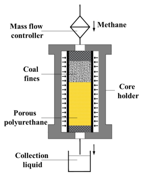
The anti-clogging performance of porous polyurethane against coal fines was evaluated using an in-house apparatus (Figure 2) built around a core holder instrumented with multiple pressure transducers (to monitor inlet, outlet, and differential pressures) and a gas mass flow controller. This setup simulates coal mine methane drainage, enabling continuous pressure monitoring, tracking of fines migration and potential clogging within the polyurethane, and collection of produced fines to quantify anti-clogging performance. Inside the core holder, the upper chamber comprised a thin-walled steel sleeve (outer diameter 38 mm, wall thickness 1 mm) packed with a 25 mm thick bed of loose coal fines, while the lower chamber housed a 50 mm thick porous polyurethane disk.
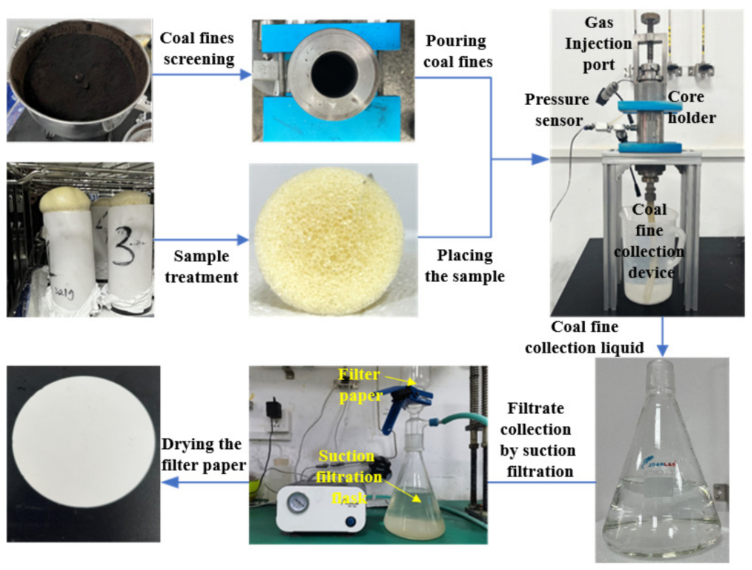
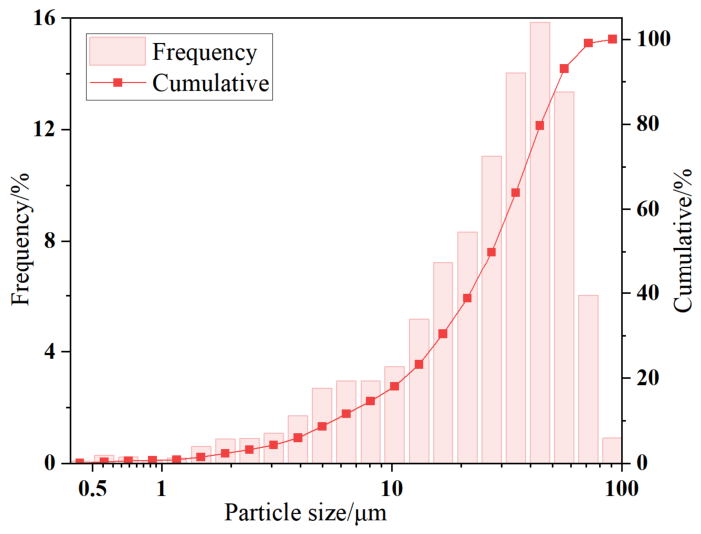
The experimental procedure (Figure 3) was as follows: the coal fines and polyurethane specimen were loaded into the core holder, all instrumentation was connected, and a confining pressure of 1 MPa was applied. The particle size distribution curve of the coal fines is presented in Figure 4. The D10, D50, and D90 values were 7 μm, 35 μm, and 67 μm, respectively, with the median size being close to the in situ median value of 38.55 μm [42]. Under room temperature conditions (20 °C), dry methane was then injected using a mass flow controller to simulate coal mine methane extraction, entraining coal fines toward and into the porous polyurethane. The inlet, outlet, and differential pressures were recorded continuously, and the effective permeability (K) of the fines–polyurethane assembly was calculated in real time using the compressible-gas form of Darcy’s law (Equation (4)). The outlet gas was bubbled through water to capture produced fines; the suspension was sampled every hour, vacuum filtered, oven-dried, and weighed to quantify coal-fine production over time. Based on field-measured methane extraction velocities (9 m/min) from a gas drainage project in Huainan, China, an initial methane injection rate of 10 L/min was used for four runs with planned durations of 3.0, 4.5, 6.0, and 7.5 h. Because no coal fines were recovered in the first three runs, the fourth run was conducted at higher flow rates while maintaining the same confining pressure and all other settings, 20.0 L/min for 4 h, during which no fines were observed, followed by 30.0 L/min. At the higher rate, coal fines were first detected at the outlet after approximately 3.5 h. To further verify the anti-clogging performance of the porous polyurethane, an additional experiment was conducted at a gas flow rate of 30.0 L/min for a continuous duration of 10 h under the same conditions. The detailed experimental parameters are summarized in Table 2.
K = 2 P 0 Q 0 μ L S ( P 1 2 P 1 P 2 )
where K is the effective permeability of the fines–polyurethane assembly, D·cm; P 0 is atmospheric pressure, 0.1 MPa; L is the length of fines–polyurethane assembly, cm; μ is the gas viscosity at the experimental temperature, mPa·s; Q 0 is the flow rate under atmospheric pressure, cm3/s; and S is the seepage area of the porous polyurethane, cm2. P 1 is the inlet pressure of the core holder, MPa; P is the pressure difference, MPa.
After the dynamic coal-fine injection phase, the methane supply was stopped, and the specimen was carefully removed from the core holder. The coal fines remaining on the upstream face were gently removed, and the specimen was reinstalled in the core holder. Clean, deionized water was then injected at steady-state flow rates of 5, 10, and 15 mL/min using a high-precision constant-flow pump. The differential pressure across the specimen was recorded after stabilization at each flow rate, and the post-test intrinsic permeability of the polyurethane itself was calculated using Darcy’s law for liquid flow. The final post-test permeability for each specimen is the average of the three steady-state values. The effective permeability measured during dynamic testing reflects the operational flow capacity of the fines–polyurethane assembly under active coal-fine loading, representing how the medium would perform during early to mid-term field gas extraction. The post-test intrinsic permeability, measured after fines deposition has stabilized, represents the residual flow capacity of the polyurethane itself after near-surface clogging.

3. Results and Discussion

The injectability of the polyurethane slurry is an important index for its application in coal mine methane extraction projects, which requires that the slurry can be smoothly injected into the well. The physical properties and foaming time of the polyurethane slurry are important criteria for evaluating the injectability of the slurry.

3.1. Performance of Polyurethane Slurry

3.1.1. Physical Properties of Polyurethane Slurry

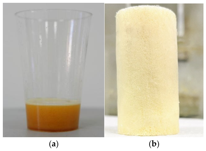
Polyurethane slurry was a yellow liquid, as shown in Figure 5, with low initial viscosity and a density of 1.127 g/cm3. At room temperature it underwent an exothermic foaming reaction: gas bubbles nucleated and grew within the matrix, driving volumetric expansion and rapid solidification. The onset of foaming occurred within 1500 s, and the rise produced an expansion factor of about five relative to the initial liquid volume. As the reaction proceeded, the viscosity increased sharply, the material gelled, and it reached a tack-free state within minutes.
The cured product was a light yellow cylindrical specimen (Figure 4) with a smooth surface free of visible defects such as cracks or voids. It exhibited a uniform, dense porous microstructure and a dry density of approximately 0.12 g/cm3. Densities were determined from mass-to-volume measurements of the molded samples; the large difference between slurry and foam densities reflected the high porosity created during foaming. The combination of low initial viscosity and rapid rise allowed the slurry to infiltrate fissures and voids before gelation, while the fast cure provides timely mechanical stabilization for reinforcement applications.

3.1.2. Foaming Time

Grouting in coal mine gas drainage boreholes requires a slurry with a controllable foaming and gelation profile so that it remains pumpable during placement and only rises once it reaches the target interval. This is achieved by tuning the catalyst system to balance the “blowing” reaction (CO2 generation) and the “gelling” reaction (urethane chain growth and cross-linking) [40]. Amines preferentially accelerate the water–isocyanate (blowing) reaction, increasing the rate of CO2 formation and foam rise [43,44]. Organotin catalysts, by contrast, favor urethane formation and cross-linking between isocyanates and polyether polyols, thereby accelerating gelation. If the blowing reaction is too fast, excessive CO2 is produced and bubbles coalesce or rupture, causing structural collapse [45]. If gelation is too rapid, gas generation and cell opening are suppressed, porosity decreases, and material performance (e.g., permeability and compliance) is compromised (see Table 3).
The catalyst dosage primarily affects the foaming time and gelation time. Tests with two catalyst types at different dosages showed clear differences in foaming kinetics. With an amine catalyst, increasing the catalyst mass fraction from 2% to 6% shortened the foaming time from approximately 40 s to 10 s. This reaction was too rapid at all tested dosages, producing swift volumetric expansion and frequent bubble collapse, which led to poor pore structure stability and repeatability in the cured specimens. In contrast, with a tin catalyst, the foaming reaction was significantly slower and more controllable: increasing the catalyst mass fraction from 2% to 6% reduced the foaming time from about 1500 s (~25 min) to 180 s (~3 min). It should be noted that the primary objective of this catalyst screening was to identify a catalyst system providing a workable time suitable for field mixing, transportation, and in situ curing, rather than to conduct a comprehensive performance optimization across all catalyst systems. Considering that downhole mixing and slurry injection through the borehole string typically take less than 5 min, the tin catalyst provides a more suitable processing window—long enough to ensure pumpability and placement, yet sufficiently fast to achieve timely gelation after emplacement. Therefore, a tin-catalyzed formulation (e.g., around 2% catalyst by mass, yielding a foaming onset of ~1500 s) was selected as the baseline catalytic system for subsequent formulation optimization and coal-fine control experiments.

3.2. Properties of Cured Porous Polyurethane

Building on the catalyst study used to control slurry foaming and gelation, we next investigated how adjusting additive types and dosages influences the properties of the cured porous polyurethane. Formulations were tuned by varying, for example, surfactants and cross-linkers/chain extenders while maintaining a practical foaming window for field injection. The resulting materials were then tested to quantify porosity, gas permeability, and uniaxial compressive strength. Porosity governs the pore architecture and directly controls permeability, which is critical for methane drainage efficiency. Uniaxial compressive strength reflects the mechanical integrity required to withstand in situ stresses and resist deformation or collapse after placement. In our study, porosity was derived from density measurements, permeability was determined from steady-state gas flow using Darcy’s law, and compressive strength was obtained from uniaxial compression tests following the applicable standard. Together, these metrics provide a balanced assessment of transport performance and structural reliability for downhole applications.

3.2.1. Impact of Additive Type on the Performance of Porous Polyurethane

To elucidate how different additives influence the properties of the cured polyurethane, we conducted a controlled comparison in which additives with distinct chemistries and functions were substituted at the same dosage under identical processing conditions. Using stoichiometric calculations based on Equations (1)–(3) and previous formulation work, the required amounts of isocyanate and polyol were determined to establish a baseline formulation. The basic formula for the polyurethane slurry, with the mass fractions of various additives, is as follows: PAPI (50%), polyether polyol (41%), catalysts (2%), foam stabilizer (3%), cell-opening agent (3%), cross-linker (5%), and foaming agent (3%). To isolate additive effects, the isocyanate index, total resin content, catalyst loading, and mixing/curing conditions were held constant unless otherwise noted. We then systematically varied the types of foam stabilizers, blowing agents, and cross-linkers to assess their impact on both the slurry behavior and the properties of the cured porous polyurethane. For each variable set, three replicate specimens were prepared and tested, and the reported values are the arithmetic means. The specific formulation adjustments and the corresponding average results are summarized in Table 4.
Foam stabilizers are incorporated to control bubble nucleation, growth, and stabilization during polyurethane foaming. By lowering interfacial tension, they facilitate cell formation while suppressing bubble coalescence and drainage, thereby reducing the likelihood of foam collapse and improving cell uniformity. Their effects are strongly dependent on chemistry and dosage. Different types of foaming stabilizers have significantly different effects. As shown in Table 4, compared with F2, F3, and F4, stabilizer F1 produced the most favorable pore architecture. At equal dosage, F1 decreased the closed-cell fraction, increased total porosity (and open-cell content), and consequently enhanced the gas permeability of the cured specimens. This behavior is consistent with an optimal balance between foam stabilization and controlled cell opening: F1 maintained stable thin films during early expansion to prevent premature coalescence, then permited selective film rupture as gelation progresses, generating a more interconnected pore network. While higher porosity can trade off against strength, within the evaluated range F1 yielded finer, more uniformly distributed cells that improved transport properties without discernible detriment to structural integrity.
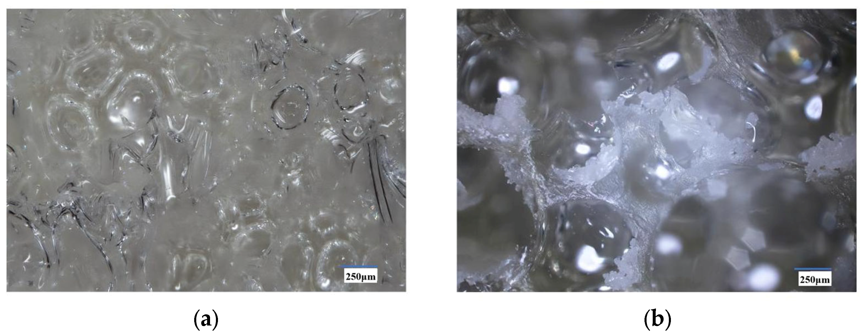
Cell-opening agents are employed to convert predominantly closed-cell foams into open-cell networks by promoting controlled film rupture during the foaming–gelation transition. By weakening cell membranes and adjusting surface energy, they increase pore connectivity, equalize internal gas pressures, and mitigate defects such as macroscopic diameter shrinkage and warpage [46]. These effects help maintain dimensional stability while enhancing transport pathways through the porous matrix. Building upon the S1–S4 baseline formulation, the introduction of a cell-opening agent under otherwise identical processing conditions resulted in a dramatic increase in the permeability of the cured specimens, from 0.04 D to 2.01 D—an improvement of approximately 50-fold (Table 4). Electron microscopy analysis (Figure 6) provides direct evidence of the underlying microstructural changes responsible for this performance enhancement. A comparison between the sample without the agent (Figure 6a) and the one containing it (Figure 6b) reveals key morphological differences: thinner cell walls, larger intercellular windows, and the formation of continuous channels, all indicative of a highly interconnected pore network. This optimized morphology not only accounts for the significant rise in permeability but also explains the effective suppression of shrinkage, as the improved connectivity reduces internal pressure differentials that would otherwise cause the collapse or contraction of closed cells.
Cross-linkers participate in intermolecular reactions that join polyurethane chains into a three-dimensional network, increasing gel strength and stiffness. As shown in Table 4, at the same dosage, the formulation with CR2 (glycerol) exhibited a permeability four times that of CR1 (1,4-butanediol). This result is consistent with the chemical differences between the two cross-linkers: CR2 (glycerol) has a functionality of three, whereas CR1 (1,4-butanediol) has a functionality of two. It is hypothesized that the higher functionality and/or lower equivalent weight of CR2 may accelerate network build-up and increase cross-link density at an earlier stage of foam rise. An earlier gel point could stabilize cell walls and struts, suppress excessive coalescence and collapse, and preserve intercellular windows, thereby yielding a higher open-cell fraction and improved permeability. Similarly, the potentially denser network provided by CR2 may contribute to enhanced compressive strength in the cured specimens.

3.2.2. Impact of Additive Dosage on the Performance of Porous Polyurethane

Building on the previous analysis, we proceeded to isolate the roles of isocyanate and the blowing agent in determining the structure and performance of the porous polyurethane. The baseline formulation was further refined based on the prior screening of additives, and the final set of reactants used in this stage is summarized as follows. The types of additives for the polyurethane slurry are as follows: PAPI (type DD-200), polyether polyol (type 4110), catalysts (type Tin), foam stabilizer (type F1), cell-opening agent (type K2), cross-linker (type CR2), and foaming agent (type Water). To identify the optimal levels of isocyanate and blowing agent, we systematically varied their loadings and evaluated the permeability and compressive strength of the cured porous polyurethane (Table 5). For each condition, three replicate specimens were prepared and tested; the reported values are arithmetic means (with variability reported where applicable). All other formulation variables (polyol blend, catalysts, foam stabilizer, cell opener/cross-linker) and processing parameters (mixing protocol, temperature, curing schedule) were held constant to isolate the effects of isocyanate index and blowing agent dosage.
According to Table 5, increasing the mass fraction of isocyanate in the polyurethane slurry raises the permeability of the cured porous polyurethane from roughly 2.0 D to about 4.0 D. This behavior reflects the dual role of isocyanate in gelation and foaming within the slurry:
~NCO + HO~ → ~NH-COO~ (gelation reaction)
~NCO + H2O → ~NHCOO-OH~ → ~NH2 + CO2↑ (gas generation)
The balance between these reactions controls pore morphology and connectivity. Under catalytic conditions, gelation can proceed very rapidly, consuming free NCO and leaving less available to react with water. When CO2 generation is insufficient to rupture thin films between cells, the material may exhibit high nominal porosity but predominantly closed cells and poor interconnectivity, which suppresses permeability. By increasing the isocyanate fraction (i.e., the NCO index), both processes are better satisfied: gelation proceeds to completion, giving a stronger, more rigid network that minimizes deformation under confining pressure and preserves pore geometry; simultaneously, adequate NCO remains to react with water, generating enough CO2 to open and interconnect pores. The result is a higher open-cell fraction and a marked increase in permeability.
As shown in Table 5, increasing the foaming-agent dosage from 2 to 5 wt% caused the permeability of the cured porous polyurethane to rise from 3.79 D to a peak of 4.72 D at 4 wt%, and then to drop to 2.58 D at 5 wt%. Over the same range, the compressive strength decreased from 1.86 MPa to 1.59 MPa. These trends indicated the existence of an optimal foaming-agent level. Mechanistically, when the foaming agent was insufficient, gas generation was inadequate and the water–isocyanate reaction did not proceed sufficiently to open intercellular windows, which limited both porosity and pore connectivity; permeability was therefore moderate. As the dosage increased toward approximately 4 wt%, gas generation became sufficient to open and interconnect pores while gelation still provided structural support, so permeability increased in step with porosity [47]. When the dosage was excessive, the rate and volume of CO2 evolution outpaced gelation, promoting bubble coalescence, film rupture, and localized foam collapse [48]. The resulting thin, discontinuous struts and deformed cells reduced compressive strength and diminished effective pore connectivity, ultimately lowering permeability. Within the studied range, maintaining a non-excessive foaming-agent level (≤4 wt%) achieved a favorable balance between open-cell fraction and mechanical integrity.

3.3. Coal-Fine Control Performance of Porous Polyurethane

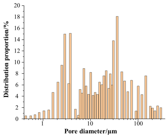
Based on the analysis of additive types and dosages, the performance of porous polyurethane was evaluated under conditions simulating practical coal mine methane extraction. A key challenge in this environment is the generation and migration of coal fines, which can clog pores and impede efficient gas recovery. This study specifically assessed the ability of porous polyurethane to mitigate coal-fine migration while maintaining adequate permeability for methane extraction. Mercury intrusion porosimetry (MIP) was used to characterize the material’s connected porosity and pore-size distribution (as shown in Figure 7). The results indicated a dominant pore-size range of 1–301 μm and a median pore diameter of 125 μm. The MIP-accessible porosity was measured at 78.9%, which was close to the total porosity estimated by density calculations (approximately 85%). This minor discrepancy suggests the presence of a small fraction of closed pores, confirming that the majority of the material’s pores were interconnected. These interconnected pores formed tortuous, multiscale flow channels that support enhanced permeability. Therefore, porous polyurethane demonstrated significant potential for controlling coal-fine migration while maintaining gas flow capacity, thereby contributing to more efficient methane extraction in coal mines.
To further evaluate the anti-clogging performance of porous polyurethane against coal fines, five flow-through experiments were conducted under simulated gas-extraction conditions at flow rates of 10, 20, and 30 L/min and durations of 3–10 h. Coal-fine production showed a clear dependence on flow rate; no fines were detected at 10 L/min over 3, 4.5, or 6 h (Runs 1, 2, and 3), and none were observed at 20 L/min over 4 h (Run 4), indicating the gas carrying capacity was insufficient to transport coal particles effectively through the complex pore network of the porous polyurethane at ≤20 L/min. Fines production began only at 30 L/min (Runs 4 and 5), with small but measurable amounts at the outlet, suggesting an onset threshold near this rate under the present conditions.
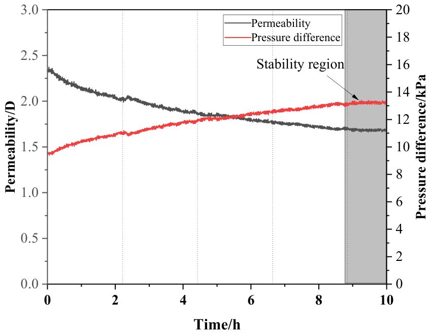
To quantify the impact of fines production on flow capacity, we examined the evolution of differential pressure and permeability across the porous polyurethane in Run 5. The results, shown in Figure 8, track the coupled changes in pressure drop and permeability during the simulated gas extraction and elucidate the permeability response associated with fines migration and deposition. The permeability of the coal-fines–polyurethane medium decreased gradually from an initial 2.35 D to 1.68 D, and then stabilized, consistent with fines migration and deposition within the pore network. As mentioned above, the median coal-fine size was 35 μm, whereas the median pore size of the polyurethane was 125 μm; therefore, coal fines will inevitably enter the internal pore space of the porous polyurethane. As extraction proceeded, two mechanisms governed the observed reduction and subsequent stabilization: (i) particle bridging at pore throats or constrictions, which limited further fines ingress; and (ii) internal deposition of particles that did enter, narrowing effective flow channels and increasing flow resistance. The ensuing stabilization indicates that the porous structure reached a quasi-steady state in which previously formed bridges and deposits constrained additional particle entry and transport, yielding a new equilibrium permeability with only limited ongoing fines release.
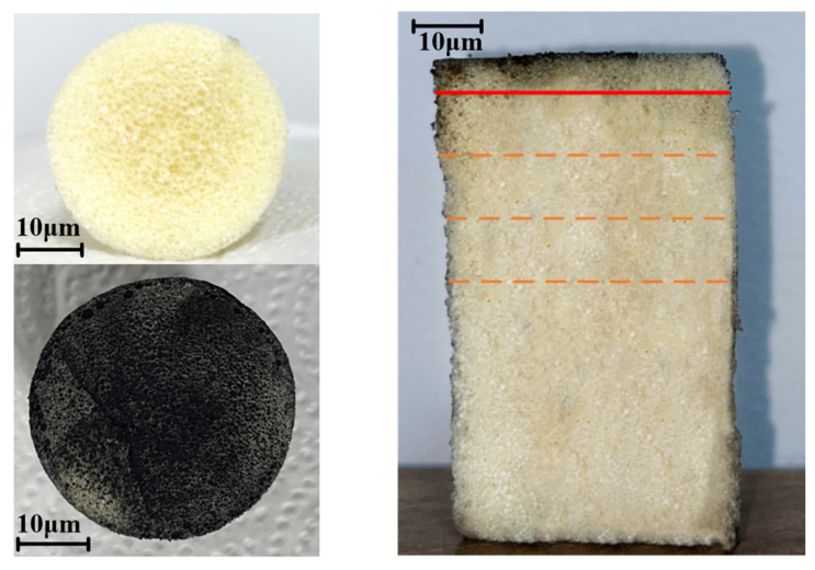
To investigate the infiltration of coal fines into porous polyurethane under simulated gas extraction, we performed a cross-sectional analysis on specimens exposed to a flow rate of 10 L/min. Cylindrical samples were sectioned along the diameter, and the spatial distribution of entrained particles within the pore network was examined (Figure 9). The sections reveal clear depth-dependent zonation from the gas-injection (upper) face. Within the first ~5 mm, the polyurethane exhibited relatively smaller pores and a densely interconnected network; coal fines were readily observed on internal surfaces and within pores, indicating advective entry and deposition during gas flow. At ~15 mm from the upper coal-fines–polyurethane interface (first dashed line in Figure 9), only trace amounts of fines were present, demonstrating a marked decrease in penetration with depth. In the lower portion of the specimen, no fines were detected, confirming that at 10 L/min coal fines did not migrate into the deeper regions of the material. The observed penetration gradient can be attributed to the combined effects of gas drag force and the porous microstructure. The complex, tortuous near-surface network acted as an efficient filter, promoting straining and early bridging. At the tested low flow rate, the gas-induced drag was insufficient to overcome adhesive/frictional interactions and geometric constrictions within narrow throats, thereby limiting deeper ingress.
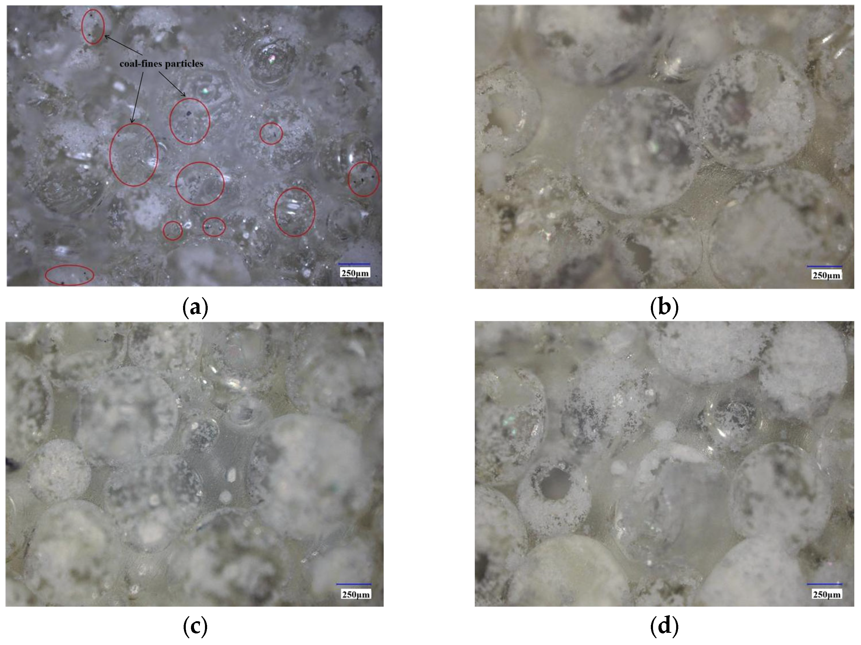
Figure 10 presents scanning electron microscopy (SEM) images acquired at distances of 5, 15, 25, and 35 mm from the coal fines–porous polyurethane interface. The cured porous polyurethane exhibited a highly open, interconnected pore network that facilitated gas flow. A pronounced depth-dependent zonation in pore morphology and fines distribution was evident. Within the first 5 mm of the interface (Figure 10a), pores were smaller and more densely distributed; coal fines were clearly trapped within the pores, especially along pore edges and throats, indicating effective near-surface interception that limited deeper migration. In contrast, at 15, 25, and 35 mm from the interface (Figure 10b–d), no coal fines were observed, demonstrating that particle transport was confined to the superficial layer under the tested conditions. This controlled penetration arises from the tortuous microstructure of the polyurethane. The dense, small-pore near-surface zone functions as a primary filtration layer, capturing particles by bridging and straining. Once partially occupied, the local reduction in pore-throat size and the rerouting of flow further suppress downstream transport, contributing to the stabilization of permeability noted above.
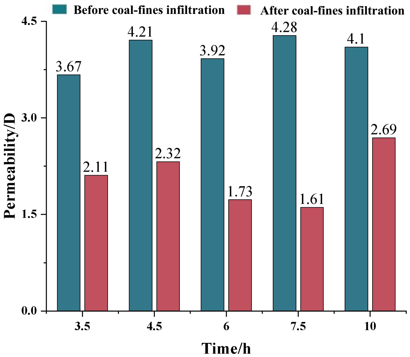
Following the coal-fine mitigation tests, the intrinsic permeability of the porous polyurethane was remeasured. Figure 11 compares permeability before and after coal-fine invasion. Across all experiments, the initial permeability was approximately 4.0 D, while the post-test permeability decreased to about 2.0 D, corresponding to an average reduction of roughly 50%. It should be noted that the four specimens in Figure 11 correspond to different coal-fine flushing durations rather than parallel replicates under identical conditions. Therefore, this comparison is intended to illustrate the general trend of permeability reduction induced by coal-fine migration and deposition, rather than to support a statistical significance test among replicate groups. The inter-test variability in permeability reduction was small, and the decrease was not strongly correlated with the mass of fines recovered at the outlet. This outcome further indicates that, under simulated gas-extraction conditions, coal fines were entrained by the flow and migrate into the near-surface layer of the polyurethane, where they were retained and impair flow capacity. The mechanism was consistent with size-selective filtration. Coarser particles were unable to pass through smaller pore throats and accumulate at pore entrances (sieving/bridging), whereas finer particles can enter the pore network but were immobilized by tortuous pathways and constrictions (straining). The accumulation and retention of fines reduced effective porosity and narrowed flow channels, leading to the observed permeability loss. Inter-test variability in permeability reduction was small, and the decrease was not strongly correlated with the mass of fines recovered at the outlet. This suggests that the primary cause of damage was near-surface deposition within the polyurethane rather than deep internal clogging or the total fines production. Despite the reduction, permeability subsequently stabilized above ~1.5 D, indicating that the fines-invaded polyurethane maintains relatively high flow capacity and remains suitable for gas drainage under the tested conditions [49]. The post-test permeability values reported here represent the stable-stage values calculated under steady differential pressure conditions, with variations of less than 0.001 D during the stabilization period. It should be noted that this study only considered the coal-fine retention behavior under dry methane gas conditions. In actual field gas drainage boreholes, however, water may be present in the borehole or in the soft coal seam itself. The seepage of water may enhance the agglomeration and adhesion of coal fines, which, relative to individual coal-fine particles, promotes deposition near the inlet end and reduces the transport and migration capacity of coal fines within the pores of the porous polyurethane. Comparative experiments under different gas–water co-flow conditions are planned for future work.

4. Conclusions

This study proposed an in situ grouting approach that forms a porous medium to control coal fines and prevent borehole clogging in methane drainage of soft coal seams. A novel polyurethane slurry was developed by optimizing key additives, and the cured porous polyurethane was characterized for compressive strength, gas permeability, and pore structure; its anti-clogging performance against coal fines was further quantified through simulated methane-extraction experiments. The main conclusions are as follows:
(1)
The polyurethane slurry exhibited good fluidity/injectability, and by adjusting the catalyst type and dosage its gel time was controllable between 10 and 1500 s. Microscopy of the cured porous polyurethane revealed an interconnected open-cell structure with favorable transport and mechanical properties: porosity ~83%, permeability >4 D, and uniaxial compressive strength of 1.5 Mpa.
(2)
Optimizing additive chemistry and dosage governed the gelation–foaming balance and pore connectivity: the formulation using F1 foam stabilizer, K2 cell-opening agent, and CR2 cross-linker with ~55 wt% isocyanate and ~4 wt% water produced an open-cell polyurethane (porosity ~87.8%) with peak permeability ~4.72 D and adequate compressive strength (~1.6 MPa). Its permeability is comparable to that of precision metal screens used in oilfield applications, while its mechanical strength is similar to that of PVC screens. Insufficient/excessive blowing or less effective additives led to poorer connectivity, lower permeability, and/or reduced strength.
(3)
The porous polyurethane possessed a highly interconnected, multiscale pore network (MIP porosity 78.9%, median pore size 125 μm, dominant range 1–301 μm) that enabled gas flow while filtering coal fines. Notably, conventional gas-drainage screens currently in use do not incorporate coal-fine prevention as a design criterion. Under simulated gas-extraction conditions, coal-fine production depended on flow rate: none occurred at ≤20 L/min, with onset near 30 L/min. Cross-sectional and SEM observations showed that fines were confined to the top ~5 mm, where smaller near-surface pores promoted bridging and straining, thereby preventing deep penetration.
(4)
Coal-fine ingress caused a moderate but acceptable loss of permeability. During dynamic testing, the coal fines–porous polyurethane medium declined from 2.35 D to ~1.68 D before stabilizing above ~1.5 D, while the intrinsic permeability of the porous polyurethane itself typically fell from ~4.0 D to ~2.0 D (a ~50% reduction). The reduction was governed primarily by near-surface deposition rather than deep clogging or the total fines mass, and the material retained sufficient permeability for methane drainage.
It should be noted that the above conclusions are drawn from laboratory-scale experiments conducted under dry methane gas conditions. Direct comparative studies against conventional screen-based completion systems under controlled conditions are needed to quantitatively evaluate relative performance in terms of clogging resistance, installation tolerance, support performance, and long-term extraction efficiency. Additionally, the influence of water presence in field boreholes on coal-fine migration and retention behavior warrants further investigation through gas–water co-flow experiments.

Author Contributions

Conceptualization, C.W. and G.Z.; methodology, C.W., J.W.; formal analysis, C.W., Y.S., S.M.; investigation, C.W., B.L., J.W. and G.Z.; data curation, S.M., W.L. and X.Z.; writing—original draft preparation, C.W., Y.S. and G.Z.; writing—review and editing, C.W. and G.Z.; supervision, C.W.; project administration, C.W.; funding acquisition, C.W. All authors have read and agreed to the published version of the manuscript.

Funding

This research was funded by the Shanxi Provincial Natural Science Basic Research Program Project, grant number 2025JC-QYCX-036 and the China Coal Technology and Engineering Group Scientific Research Project, grant number 2025-TD-QZ030.

Data Availability Statement

The original contributions presented in this study are included in the article. Further inquiries can be directed to the corresponding authors.

Conflicts of Interest

Authors Chuanliu Wang, Jiale Wang, Shaoming Ma and Weiwei Liu were employed by the Xi’an Research Institute, China Coal Technology and Engineering Group Corporation. The remaining authors declare that the research was conducted in the absence of any commercial or financial relationships that could be construed as a potential conflict of interest. The authors declare that this study received funding from the China Coal Technology and Engineering Group Corporation. The funder was not involved in the study design, collection, analysis, interpretation of data, the writing of this article or the decision to submit it for publication.

References

  1. Cheng, C.; Hu, Q.; Luo, Y.; Wang, B.; Tao, R.; Sun, Y. Experimental study of deformation evolution around the gas extraction borehole in a composite stratum. Fuel 2025, 381, 133296. [Google Scholar] [CrossRef]
  2. Xu, H.; Qin, Y.; Yang, D.; Wang, G.; Huang, Q.; Zhang, F. Experimental investigation of gas diffusion kinetics and pore-structure characteristics during coalbed methane desorption within a coal seam. Gas Sci. Eng. 2024, 121, 205173. [Google Scholar] [CrossRef]
  3. Zhang, Y.; Su, G.; Zheng, L.; Liu, D.; Guo, Z.; Wei, P. The environmental friendliness of fuzzy-ball drilling fluids during their entire life-cycles for fragile ecosystems in coalbed methane well plants. J. Hazard. Mater. 2019, 364, 396–405. [Google Scholar] [CrossRef] [PubMed]
  4. Xi, X.; Tao, Y.; Jiang, S.; Yin, C. Study on the formation mechanism and mechanical properties of composite foam slurry material for mine plugging. Energy 2023, 281, 128295. [Google Scholar] [CrossRef]
  5. Yi, M.; Wang, L.; Hao, C.; Liu, Q.; Wang, Z. Method for designing the optimal sealing depth in methane drainage boreholes to realize efficient drainage. Int. J. Coal Sci. Technol. 2021, 8, 1400–1410. [Google Scholar] [CrossRef]
  6. Lou, Z.; Wang, K.; Zhao, W.; Wei, G.; Yao, H.; Qin, H.; Wei, X.; Song, H. Experimental investigation on visualization and quantitative characterization of filling and plugging performances of fractures in coal. Phys. Fluids 2024, 36, 036609. [Google Scholar] [CrossRef]
  7. Deetjen, T.A.; Azevedo, I.L. Climate and Health Benefits of Rapid Coal-to-Gas Fuel Switching in the U.S. Power Sector Offset Methane Leakage and Production Cost Increases. Environ. Sci. Technol. 2020, 54, 11494–11505. [Google Scholar] [CrossRef] [PubMed]
  8. Xi, X.; Shi, Q.; Jiang, S.; Wang, K.; Wu, Z.; Shao, H. Effects of Graphene Oxide on the Mechanical and Microscopic Characteristics of Cement-Based Plugging Material for Preventing Spontaneous Combustion of Coal. Energy Fuels 2020, 34, 6346–6354. [Google Scholar] [CrossRef]
  9. Lou, Z.; Wang, K.; Kang, M.; Zhao, W.; Wei, G.; Yue, J.; Yao, H. Plugging methods for underground gas extraction boreholes in coal seams: A review of processes, challenges and strategies. Gas Sci. Eng. 2024, 122, 205225. [Google Scholar] [CrossRef]
  10. Zhou, F.; Xia, T.; Wang, X.; Zhang, Y.; Sun, Y.; Liu, J. Recent developments in coal mine methane extraction and utilization in China: A review. J. Nat. Gas Sci. Eng. 2016, 31, 437–458. [Google Scholar] [CrossRef]
  11. Yuan, L. Theory and practice of integrated coal production and gas extraction. Int. J. Coal Sci. Technol. 2015, 2, 3–11. [Google Scholar] [CrossRef]
  12. Karacan, C.Ö.; Ruiz, F.A.; Cotè, M.; Phipps, S. Coal mine methane: A review of capture and utilization practices with benefits to mining safety and to greenhouse gas reduction. Int. J. Coal Geol. 2011, 86, 121–156. [Google Scholar] [CrossRef]
  13. Noack, K. Control of gas emissions in underground coal mines. Int. J. Coal Geol. 1998, 35, 57–82. [Google Scholar] [CrossRef]
  14. Awan, F.U.R.; Arif, M.; Iglauer, S.; Keshavarz, A. Coal fines migration: A holistic review of influencing factors. Adv. Colloid Interface Sci. 2022, 301, 102595. [Google Scholar] [CrossRef] [PubMed]
  15. Han, W.; Wang, Y.; Li, Y.; Ni, X.; Wu, X.; Yang, J.; Zhao, S. Coal fines migration, deposition, and output simulation during drainage stage in coalbed methane production. Energy Fuels 2021, 35, 4901–4913. [Google Scholar] [CrossRef]
  16. Liu, Q.; Cheng, Y.; Yuan, L.; Fang, Y.; Shi, D.; Kong, S. A new effective method and new materials for high sealing performance of cross-measure CMM drainage boreholes. J. Nat. Gas Sci. Eng. 2014, 21, 805–813. [Google Scholar] [CrossRef]
  17. Yang, Y.; Cui, S.; Ni, Y.; Zhang, G.; Li, L.; Meng, Z. Key technology for treating slack coal blockage in CBM recovery: A case study from multi-lateral horizontal wells in the Qinshui Basin. Nat. Gas Ind. B 2016, 3, 66–70. [Google Scholar] [CrossRef]
  18. Huang, Z.; Li, G.; Yan, X.; Wang, K.; Shen, R.; Jin, L. Comparison experiment on steel and non-steel slotted screen pipes used in coalbed methane wells. Pet. Explor. Dev. 2012, 39, 522–527. [Google Scholar] [CrossRef]
  19. Zhao, Y.; Shi, Z.; Hao, S.; Liu, J.; Yang, Z.; Wang, S. Well Completion Technology Using Screen Pipe for Horizontally-intersected Well in Soft Coal Seam. Procedia Eng. 2014, 73, 311–317. [Google Scholar] [CrossRef]
  20. Zhang, H. Application of high efficient gas drainage technology with double casing pipe to mining seam. Coal Sci. Technol. 2013, 41, 64–67. [Google Scholar] [CrossRef]
  21. Wang, L.; Yao, N.; Yao, Y.; Wang, Y.; Zhang, J.; Fang, J.; Wei, H. Research progress of drilling and borehole completion technologies in broken soft coal seam in underground coal mine. Coal Geol. Explor. 2021, 49, 285–296. [Google Scholar]
  22. Niu, D. Gas pre-drainage technology with full length casing for borehole drilled along low permeability soft seam. Coal Sci. Technol. 2013, 41, 90–92+116. [Google Scholar] [CrossRef]
  23. Orhan, N. Effect of Different Screen Types on Head Loss in Deep Wells Used for Irrigation. Turk. J. Civ. Eng. 2023, 34, 61–82. [Google Scholar] [CrossRef]
  24. Yang, S.; Wen, G.; Yan, F.; Zhang, M.; Zhao, X. Evaluating the maximum rate of penetration for drilling borehole in soft coal seam. Energy Sci. Eng. 2020, 8, 3273–3284. [Google Scholar] [CrossRef]
  25. Zheng, C.; Chen, Z.; Kizil, M.; Aminossadati, S.; Zou, Q.; Gao, P. Characterisation of mechanics and flow fields around in-seam methane gas drainage borehole for preventing ventilation air leakage: A case study. Int. J. Coal Geol. 2016, 162, 123–138. [Google Scholar] [CrossRef]
  26. Zhang, B.; Yu, Y.; Gao, X.; Wu, Q.; Zhang, Q.; Liu, C. Experimental Study on the Optimization of Polymer-Modified Cement-Based Composite Sealing Materials and Mechanical Properties and Permeability of Cemented Coal Bodies. Front. Mater. 2022, 9, 774887. [Google Scholar] [CrossRef]
  27. Wang, Z.; Sun, Y.; Wang, Y.; Zhang, J.; Sun, Z. A coupled model of air leakage in gas drainage and an active support sealing method for improving drainage performance. Fuel 2019, 237, 1217–1227. [Google Scholar] [CrossRef]
  28. Xiang, X.; Zhai, C.; Xu, Y.; Yu, X.; Xu, J. A flexible gel sealing material and a novel active sealing method for coal-bed methane drainage boreholes. J. Nat. Gas Sci. Eng. 2015, 26, 1187–1199. [Google Scholar] [CrossRef]
  29. Fu, J.; Li, X.; Wang, Z. A novel sealing material and a bag-grouting sealing method for underground CBM drainage in China. Constr. Build. Mater. 2021, 299, 124016. [Google Scholar] [CrossRef]
  30. Zhang, X.; Wang, E. Study on Ratio Optimization and Diffusion-Gelation Process of Polymer Grouting Materials for Fracture Filling in Underground Mines. Materials 2024, 17, 3064. [Google Scholar] [CrossRef] [PubMed]
  31. Zhang, Q.; Hu, X.; Wu, M.; Zhao, Y.Y.; Yu, C. Effects of different catalysts on the structure and properties of polyurethane/water glass grouting materials. J. Appl. Polym. Sci. 2018, 135, 46460. [Google Scholar] [CrossRef]
  32. Zhang, H.; Yao, S.; Wang, J.; Hou, C.; Guan, X.; Zou, D. A novel CO2 foaming agent for the preparation of foamed sulfoaluminate cement material: Application to coal mine filling. J. Build. Eng. 2022, 62, 105353. [Google Scholar] [CrossRef]
  33. Henrique, B.Z.J.; Mohammad, H.; Chenxi, W.; Mahmood, S.; Alireza, N. A novel laboratory technique for open-hole gravel-pack design. J. Pet. Sci. Eng. 2022, 215, 110713. [Google Scholar] [CrossRef]
  34. Wang, C.; Pang, Y.; Mahmoudi, M.; Haftani, M.; Salimi, M.; Fattahpour, V.; Nouri, A. A set of graphical design criteria for slotted liners in steam assisted gravity drainage production wells. J. Pet. Sci. Eng. 2020, 185, 106608. [Google Scholar] [CrossRef]
  35. Wang, C.; Pallares, J.D.M.; Haftani, M.; Nouri, A. Developing a methodology to characterize formation damage (pore plugging) due to fines migration in sand control tests. J. Pet. Sci. Eng. 2020, 186, 106793. [Google Scholar] [CrossRef]
  36. Dawson, M.A.; Germaine, J.T.; Gibson, L.J. Permeability of open-cell foams under compressive strain. Int. J. Solids Struct. 2006, 44, 5133–5145. [Google Scholar] [CrossRef]
  37. Wang, L.; Xue, Y.; Wang, X.; Zhu, L.; Cao, X.; Ge, R. Effect of aggregate gradation on pore structure evolution and mechanical performance of coal gangue-fly ash cemented backfill: Insights from NMR. Powder Technol. 2026, 482, 122775. [Google Scholar] [CrossRef]
  38. Xue, Y.; Wang, L.; Cai, Y.; Liu, J.; Ranjith, P.G.; Gao, F.; Xie, H.; Liu, Y. Effects of heating–cooling on the mechanical properties and damage evolution of granite for underground cryogenic storage. Acta Geotech. 2026, 1–21. [Google Scholar] [CrossRef]
  39. Barksby, N.; Dormish, J.F.; Haider, K.W. Polyurethane Synthesis. In Encyclopedia of Polymeric Nanomaterials; Kobayashi, S., Müllen, K., Eds.; Springer: Berlin/Heidelberg, Germany, 2015; pp. 2091–2103. [Google Scholar]
  40. Gertig, C.; Erdkamp, E.; Ernst, A.; Hemprich, C.; Kröger, L.; Langanke, J.; Bardow, A.; Leonhard, K. Reaction Mechanisms and Rate Constants of Auto-Catalytic Urethane Formation and Cleavage Reactions. ChemistryOpen 2021, 10, 534. [Google Scholar] [CrossRef] [PubMed]
  41. GB/T 8813-2020; Rigid Cellular Plastics—Determination of Compression Properties. China Standards Press: Beijing, China, 2020.
  42. Xue, A.; Gao, W.; Mao, T. Type selection and optimization of filtration and separation equipment in coalbed methane gathering station. Gas Heat 2015, 35, 21–23. [Google Scholar] [CrossRef]
  43. McKenna, S.T.; Hull, T.R. The fire toxicity of polyurethane foams. Fire Sci. Rev. 2016, 5, 3. [Google Scholar] [CrossRef]
  44. Gama, N.V.; Ferreira, A.; Barros-Timmons, A. Polyurethane Foams: Past, Present, and Future. Materials 2018, 11, 1841. [Google Scholar] [CrossRef] [PubMed]
  45. Wang, Y.; Liang, S.; Tian, C.; Wang, J. Synthesis and properties of biodegradable polyurethane foams. New Chem. Mater. 2011, 39, 57–59+79. [Google Scholar]
  46. Sauter, T.; Lutzow, K.; Schossig, M.; Kosmella, H.; Weigel, T.; Kratz, K.; Lendlein, A. Pore morphology as structural parameter to tailor the shape-memory effect of polyuetherurethane foams. In Abstracts of Papers of the American Chemical Society; American Chemical Society: Washington, DC, USA, 2013; Volume 245. [Google Scholar]
  47. Wang, Z.; Wang, Z.; Wang, X.; Yang, B.; Li, S. Effect of formula compositions on compressive strength of polyurethane grouting materials. China Plast. 2023, 37, 7–14. [Google Scholar] [CrossRef]
  48. Zhang, X.; Cao, Y. Effect of cross linkage on properties of transparent polyurethane elastomer. Polym. Mater. Sci. Eng. 2002, 18, 122–125. [Google Scholar] [CrossRef]
  49. Tiancheng, X.; Yingchun, W.; Ziliang, L.; Biao, L.; Daiyong, C.; Anmin, W. Experimental Investigation on the Impact of Coal Fines Migration on Pores and Permeability of Cataclastic Coal. ACS Omega 2023, 8, 31246–31255. [Google Scholar] [CrossRef]
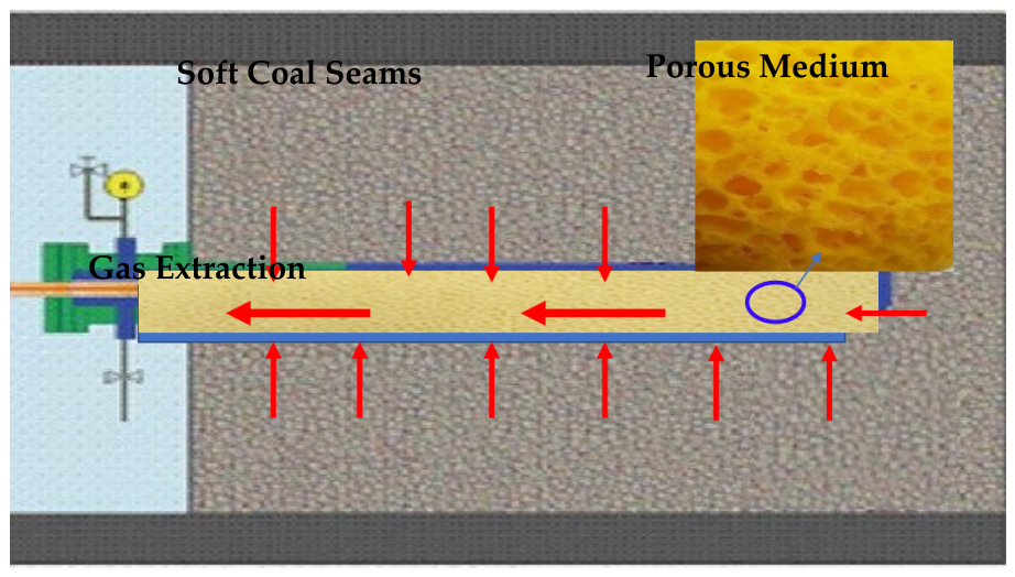
Figure 1. Schematic diagram of the screen-free completion method for gas extraction in soft coal seams.
Processes 14 02419 g001
Figure 2. Schematic diagram of the coal-fine control performance testing device.
Processes 14 02419 g002
Figure 3. Schematic diagram of experimental process.
Processes 14 02419 g003
Figure 4. The particle size distribution curve of the coal fines.
Processes 14 02419 g004
Figure 5. Photograph of porous polyurethane slurry: (a) polyurethane slurry; (b) prepared porous polyurethane.
Processes 14 02419 g005
Figure 6. Electron microscope image of pore structure in porous polyurethane: (a) without adding cell-opening agents; (b) after adding cell-opening agents.
Processes 14 02419 g006
Figure 7. Pore distribution of porous polyurethane.
Processes 14 02419 g007
Figure 8. Variation in gas permeability and pressure difference in coal fines and porous polyurethane during the simulated gas extraction process.
Processes 14 02419 g008
Figure 9. Porous polyurethane specimens before (upper left) and after (lower left) coal-fine infiltration, and the longitudinal cross-sectional view of the infiltrated polyurethane column (right). The solid red line indicates 5 mm from the upper coal-fines–polyurethane interface, and the dashed orange lines are spaced at 5 mm intervals.
Processes 14 02419 g009
Figure 10. Electron microscope images of porous polyurethane at different positions: (a) 5 mm from the top surface; (b) 15 mm from the top surface; (c) 25 mm from the top surface; (d) 35 mm from the top surface.
Processes 14 02419 g010
Figure 11. Permeability changes in porous polyurethane before and after coal-fine infiltration.
Processes 14 02419 g011
Table 1. Main raw materials used in the preparation of porous polyurethane slurry.
Reagent FunctionReagent NameSpecificationManufacture
Main componentsPAPIIndustrial gradeWanhua Energy Saving Technology Group Co., Ltd., Yantai, China
Polyether polyolIndustrial gradeTianjin Third Petrochemical Plant, Tianjin, China
Foaming agent99.99Ruixi Chemical Water Treatment Plant, Beijing, China
CatalystsT-9Industrial gradeWuhan Litai Chemical Co., Ltd., Wuhan, China
Cross-linkerCR1Industrial gradeShanghai McLean Biochemical Technology Co., Ltd., Shanghai, China
CR2Industrial gradeXilong Science Co., Ltd., Shanghai, China
Foam stabilizerF1Industrial gradeJiangsu MeiSide Chemical Co., Ltd., Nanjing, China
F2Industrial gradeBYK-Chemie GmbH, Shanghai, China
F3Industrial gradeGuangzhou Xinguan Chemical Technology Co., Ltd., Guangzhou, China
F4Industrial gradeGuangzhou Dejing Chemical Co., Ltd., Guangzhou, China
Cell-opening agentK1Industrial gradeJiangsu MeiSide Chemical Co., Ltd., Nanjing, China
K2Industrial gradeDongguan Guangsiyuan Polyurethane Materials Co., Ltd., Dongguan, China
Table 2. Experimental parameters for anti-clogging performance of coal-fine tests.
RunsInitial Permeability of Porous Polyurethane (D)Gas Injection Rate
(L·min−1)
Gas Injection
Duration (h)
Coal Fines Produced (Yes/No)
13.67103.0No
24.12104.5No
33.92106.0No
44.284 h @ 20 L/min;
next 3.5 h @ 30 L/min.
7.5Yes
54.1030 L/min10.0Yes
Table 3. Catalyst types and foaming time.
Types of CatalystsMass Fraction/%Foaming Time/s
Tin compounds21500
4600
6180
Amine240
415
610
Table 4. Permeability and uniaxial compressive strength of porous polyurethane specimens prepared with different additive types.
VariableRunsFoam Stabilizer TypeCell-Opening AgentCross-Linker TypePermeability
/D
Compressive Strength/MPa
Foaming agentS1F1No cell-opening agent addedCR10.07 ± 0.011.72 ± 0.15
S2F2
S3F3
S4F40.04 ± 0.011.70 ± 0.11
Cell-opening agentS4F1K1CR10.62 ± 0.021.62 ± 0.15
S5K20.61 ± 0.031.66 ± 0.12
Cross-linkersS6F1K1CR10.57 ± 0.011.65 ± 0.20
S7CR22.01 ± 0.021.78 ± 0.24
Note: S2 and S3 samples are not involved in subsequent performance tests due to their small foaming expansion volume.
Table 5. Permeability and uniaxial compressive strength of porous polyurethane specimens prepared with different additive amounts.
VariableNumberIsocyanate Mass Fraction/%Foaming Agent Mass Fraction/%Porosity/%Permeability/DCompressive Strength/MPa
Isocyanate dosageS150284.8 ± 0.32.12 ± 0.311.70 ± 0.14
S255285.0 ± 0.23.79 ± 0.201.86 ± 0.17
Blowing agent dosageS355386.2 ± 0.44.22 ± 0.081.70 ± 0.12
S455487.8 ± 0.34.72 ± 0.121.61 ± 0.16
S555585.0 ± 0.32.58 ± 0.061.59 ± 0.13
Disclaimer/Publisher’s Note: The statements, opinions and data contained in all publications are solely those of the individual author(s) and contributor(s) and not of MDPI and/or the editor(s). MDPI and/or the editor(s) disclaim responsibility for any injury to people or property resulting from any ideas, methods, instructions or products referred to in the content.