Article

Experimental Study on Atomization Characteristics of Droplet Field in the Downstream Region of Hydraulic Nozzles Under Co-Flow Disturbance


1
School of Energy and Building Environment, Guilin University of Aerospace Technology, Guilin 541004, China
2
University Engineering Research Center of Green Upgrade Key Technology for Energy Industry, Guilin 541004, China
3
School of Resource & Environment and Safety Engineering, Hunan University of Science and Technology, Xiangtan 411201, China
*
Author to whom correspondence should be addressed.
Processes 2026, 14(13), 2206; https://doi.org/10.3390/pr14132206
Submission received: 28 May 2026 / Revised: 25 June 2026 / Accepted: 3 July 2026 / Published: 6 July 2026
(This article belongs to the Section Energy Systems)

Abstract

Hydraulic nozzles are widely utilized for dust removal, cooling, and waste heat recovery in mining production. Nevertheless, the influence of co-flow disturbance on the atomization characteristics within the downstream region of droplet fields remains inadequately understood. In this study, three typical hydraulic nozzles were selected, and the atomization characteristics of the downstream region under different co-flow disturbance intensities were experimentally investigated. The results reveal that increasing co-flow disturbance velocity does not intensify the reduction in sauter mean diameter (SMD), but markedly reduces the dispersed phase fraction (DPF). Under four co-flow disturbance velocities (1.5, 3.0, 4.5, and 6.0 m/s), the relative reduction rates of mean SMD are 6.77%, 3.27%, 4.42% and 2.60%, while those of mean DPF are 13.86%, 35.85%, 52.88%, and 61.86% (e.g., hollow-cone nozzle), respectively. The variation in SMD is achieved through the redistribution of cumulative volume among CV1, CV2, CV3, and CV4. As the velocity increases from 0 to 3 m/s, the mean SMD of the three hydraulic nozzles exhibits a decreasing trend, which can be directly attributed to the continuous increase in the total cumulative volume of CV1 and CV2, and the continuous decrease in those of CV3 and CV4. For the hollow-cone and solid square-cone nozzles, the SMD first decreases and then increases, with the turning point occurring at 3.0 m/s, consistent with the variation trend of cumulative volume fractions. In contrast, for the solid-cone nozzle, the SMD continues to decrease at velocities exceeding 3.0 m/s. This work provides both a fundamental understanding of atomization characteristics in the downstream region of hydraulic nozzles under co-flow disturbance and practical guidance for velocity control in mine spray systems.

1. Introduction

The rapid adoption of mechanized and intelligent technologies in mine production has markedly boosted operational efficiency, accompanied by increased dust pollution and high-temperature thermal hazards in the mining process [1,2]. Such hazards impair workers’ occupational health and constrain green mine construction and the sustainable development of the mining industry [3,4,5]. Faced with this challenge, global researchers have fully considered engineering constraints including economic feasibility, spatial limitations, and adaptability to working conditions. It has been verified that atomizing continuous fluid media into discrete droplet groups via nozzles can expand droplet coverage and improve operational efficiency—a method that provides an effective approach to dust pollution control and airflow temperature reduction [6,7].
Studies have shown that the atomization performance of hydraulic nozzles is related to factors such as water supply pressure, atomization medium, and nozzle structure. Specifically, with increasing water supply pressure, the droplet size of the spray field decreases, thereby enhancing the efficiency of both spray cooling and waste heat recovery [8,9]. In terms of modifying the atomization medium, magnetized industrial water or water containing a certain proportion of micro/nano bubbles can significantly reduce the SMD of the nozzle [10,11]. In terms of nozzle structure optimization, new supersonic pneumatic atomization dust removal nozzles and gas–liquid mixed nozzles deliver superior atomization performance, enhancing the coagulation effect between droplets and dust particles and thereby improving dust removal efficiency [12,13,14].
Previous studies have clarified the correlations among droplet size, nozzle structure, and water supply pressure, providing crucial theoretical support for both experimental tests and engineering applications of hydraulic nozzles. Experimental studies have shown that the effective range of the spray droplet field extends up to 1000 mm from the nozzle outlet [15]. However, most studies mainly focus on the primary and secondary breakup regions near the nozzle outlet [16,17]. A single nozzle type is generally selected for investigation, with measuring points distributed axially 0–400 mm downstream of the nozzle outlet in the droplet field [18,19]. In contrast, the spray region further downstream—an important region for dust capture and cooling in underground mine roadways—has received considerably less research attention and warrants a systematic investigation of its atomization characteristics. In addition, to guarantee the air quality of roadways in mine production, forced ventilation measures are adopted, resulting in airflow velocity in underground roadways reaching up to 6 m/s [8,20,21,22]. Hydraulic nozzles are the most widely used atomization devices in mine dust suppression and cooling systems [23]. Some scholars have noticed the influence of co-flow disturbance on atomization performance and carried out comparative experiments under conditions with and without co-flow disturbance. The results show that, under a co-flow velocity of 0.4 m/s, the overall moving velocity of droplets in the entire flow field increases, while droplet size decreases slightly, and the droplet size distribution becomes more uniform [24,25].
In summary, current investigations into hydraulic nozzles mainly concentrate on macroscopic spray parameters near the nozzle outlet under static conditions, lacking systematic analyses on the atomization characteristics of different hydraulic nozzles in the downstream region under variable co-flow disturbances. Unlike prior studies focused primarily on the near-nozzle zone or weak airflow conditions, this work aims to systematically investigate atomization characteristics in the downstream region across a broad range of co-flow velocities.
Therefore, in this study, three typical hydraulic nozzles with different spray patterns were selected as atomization devices for comparative analysis. An experimental platform was established to explore the atomization characteristics of spray droplet fields under various co-flow disturbance intensities. The influence of co-flow airflow disturbance on atomization characteristics is clarified by analyzing the variation law of SMD and DPF, and the corresponding atomization mechanism of droplet groups under co-flow disturbance is revealed via piecewise analysis of particle size distribution. This study lays an important theoretical foundation for the formulation of technical measures related to dust control, high-temperature hazard mitigation, and waste heat recovery in mine production, as well as the co-flow velocity regulation of atomization equipment.

2. Materials and Methods

2.1. Experimental Platform

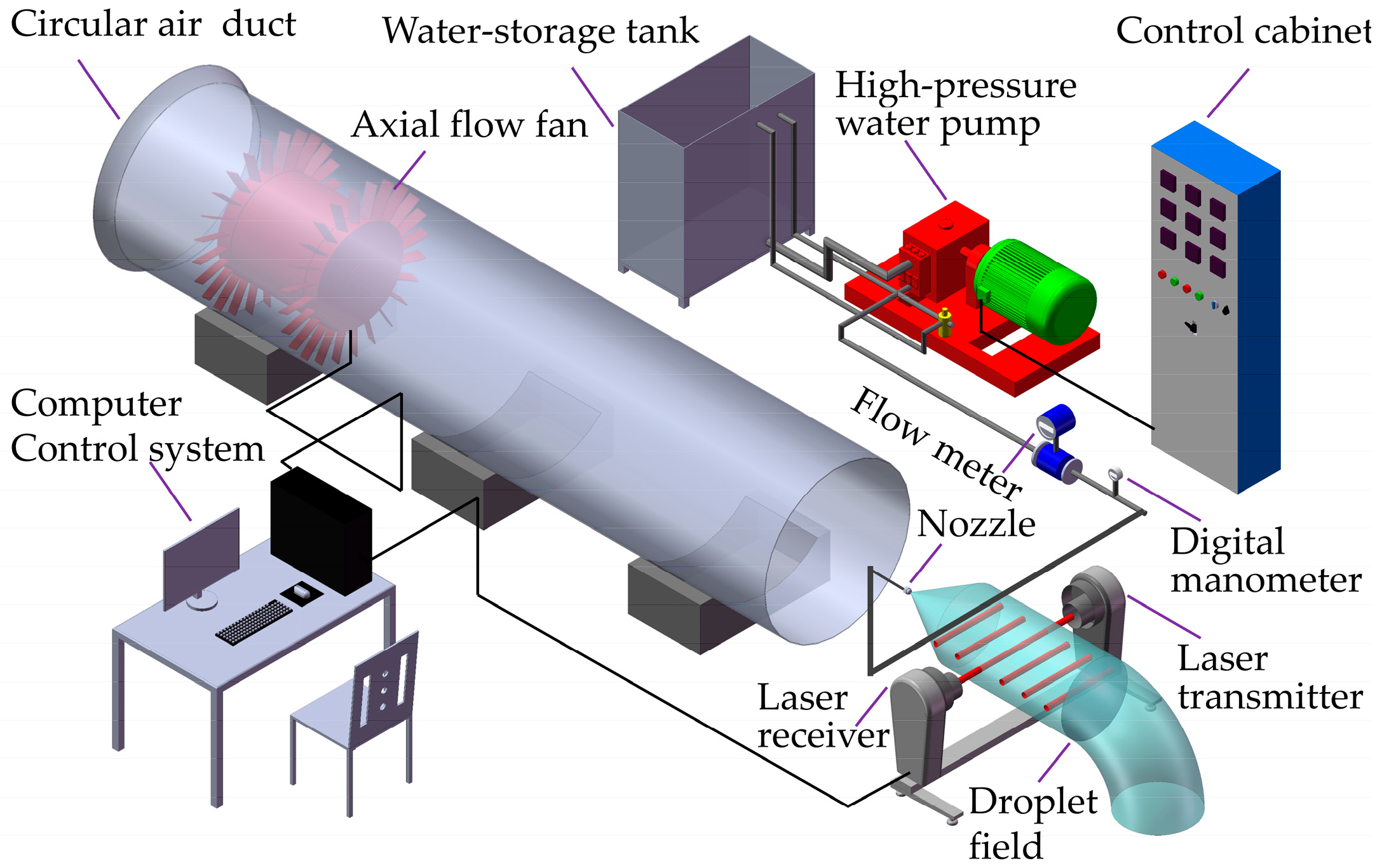
To investigate the effects of co-flow disturbance on the downstream region of the droplet field, an experimental system was established, as shown in Figure 1.
The experimental system comprises a spray generation unit, a controlled airflow supply system, and a Malvern spray particle size analyzer (Malvern Panalytical Co., Ltd., Malvern, UK). The spray generation unit includes a water storage tank, a BPZ75/12 high-pressure water pump, a frequency converter control cabinet, an intelligent electromagnetic flowmeter, a digital pressure gauge, piping, and experimental nozzles. The frequency converter enables stepless adjustment of the outlet water pressure to meet specific experimental requirements, and the entire system operates at a pressure control accuracy of ±0.01 MPa, with real-time feedback provided by the digital pressure gauge. The controlled airflow supply system comprises an axial flow fan, a circular air duct, and a computer control terminal. The computer control terminal regulates the airflow velocity inside the circular air duct by adjusting the rotational speed of the axial flow fan impeller. The system operates with a velocity control accuracy of ±0.2 m/s. The maximum adjustable air volume within the duct reaches 18.2 m3/s, with the circular air duct measuring 18,000 mm in length, the circular air duct having a diameter of 1000 mm, and the axial flow fan rated at 18.5 kW. The Malvern spray particle size analysis system is composed of a laser transmitter, a receiver, a computer, and data connection cables. The computer records atomization characteristics (e.g., SMD and DPF) in real time during measurements, outputting one set of data every second. The droplet size measurement range of the Malvern spray particle size analyzer spans 0.1–2500 μm. Prior to the experiments, the instrument was calibrated in accordance with the calibration procedures outlined in the user manual of the Malvern spray droplet size analyzer.
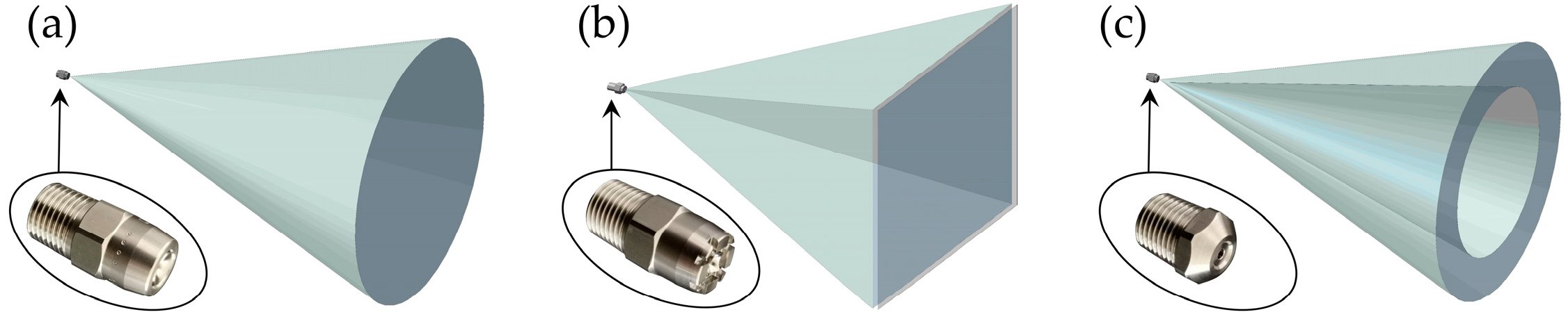
As shown in Figure 1, the high-pressure pump extracts water from the storage tank and pressurizes the fluid for delivery through pipelines. After flowing through the internal passages of the nozzle, the pressurized water atomizes at the nozzle outlet, generating a complete droplet field. Under the condition of co-flow disturbance, the Malvern spray particle size analysis system measures the atomization parameters of the droplet field generated by the experimental nozzle. To explore the influence of co-flow disturbance on the atomization parameters of different types of hydraulic nozzles, three hydraulic nozzles produced by Chinei Droplet Trading Co., Ltd., Shanghai, China, were selected, as shown in Figure 2. Specifically, both the solid conical nozzle and solid square conical nozzle are equipped with built-in X-shaped vanes, and both have an outlet diameter of 2.5 mm. The difference in outlet structure between these two solid nozzles results in distinct spray patterns. The hollow conical nozzle adopts a novel built-in vane structure and is less prone to clogging, with an outlet diameter of 2.5 mm.

2.2. Test Procedure

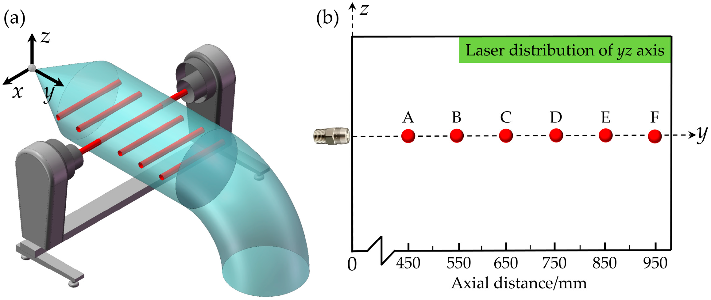
Figure 3 presents the arrangement of six measurement points along the y-axis of the yz reference plane in the downstream region. These points are designated as A, B, C, D, E, and F, and their coordinates (unit: mm) are (0, 450, 0), (0, 550, 0), (0, 650, 0), (0, 750, 0), (0, 850, 0), and (0, 950, 0), respectively. The Malvern spray particle size analyzer is installed downstream of the air duct, with a horizontal distance of 300 mm between the analyzer and the duct outlet. This arrangement enables accurate reproduction of the actual working condition where the spray droplet field is subjected to a uniform co-flow. Five co-flow velocities (0, 1.5, 3.0, 4.5, and 6.0 m/s) were set in the circular duct via the computer control terminal. The co-flow airflow is generated by ambient air driven by the impeller of an axial flow fan. The temperature and relative humidity of the ambient air are 26 °C and 35%, respectively. The airflow direction within the circular duct was aligned with the trajectory of spray droplets ejected from the nozzle. To ensure the experimental results align with actual engineering conditions, the water supply pressure was set to 0.7 MPa. This value is within the typical operating range of hydraulic nozzles, which is generally no more than 1 MPa in practical engineering applications [8,22,26,27]. The atomization medium was tap water at 20–22 °C, with physicochemical properties including a viscosity of 0.958–1.002 mPa·s, a surface tension of 0.0723–0.0726 N/m, and a conductivity of ~300–400 μS/cm. Considering the small temperature difference between the co-flow disturbance airflow and the atomizing medium, evaporation effects can be neglected under the experimental conditions.
Based on the experimental parameters defined above, the test procedure can be summarized as follows:
(1)
Fill the water tank of the spray system to two-thirds of its total capacity, check all pipeline connections for leakage, install the solid-cone nozzle, and set the co-flow velocity in the circular duct to 0 m/s through the computer control terminal.
(2)
According to the measurement point layout shown in Figure 3, adjust the position of the Malvern spray particle size analyzer so that the laser column coincides with measuring point A. Turn on the control cabinet, and adjust the water supply pressure to 0.7 MPa using the pressure regulating valve.
(3)
After measuring the droplet parameters via the computer control system, reset the water supply pressure to zero, then adjust the position of the Malvern spray particle size analyzer, and complete the atomization parameter measurements sequentially at measuring points B, C, D, E and F.
(4)
Adjust the co-flow velocity in the circular duct to 1.5 m/s and repeat the measurement procedure described in Steps (2)–(3). Then set the duct velocity to 3.0 m/s, 4.5 m/s, and 6.0 m/s in sequence, and perform the same measurements under each corresponding co-flow velocity condition.
(5)
For the solid square-cone nozzle and hollow-cone nozzle, repeat the measurement procedures described in Steps (1)–(4), respectively, thereby completing the atomization parameter measurements for each nozzle type under all five co-flow disturbance conditions.

2.3. Analytical Methods

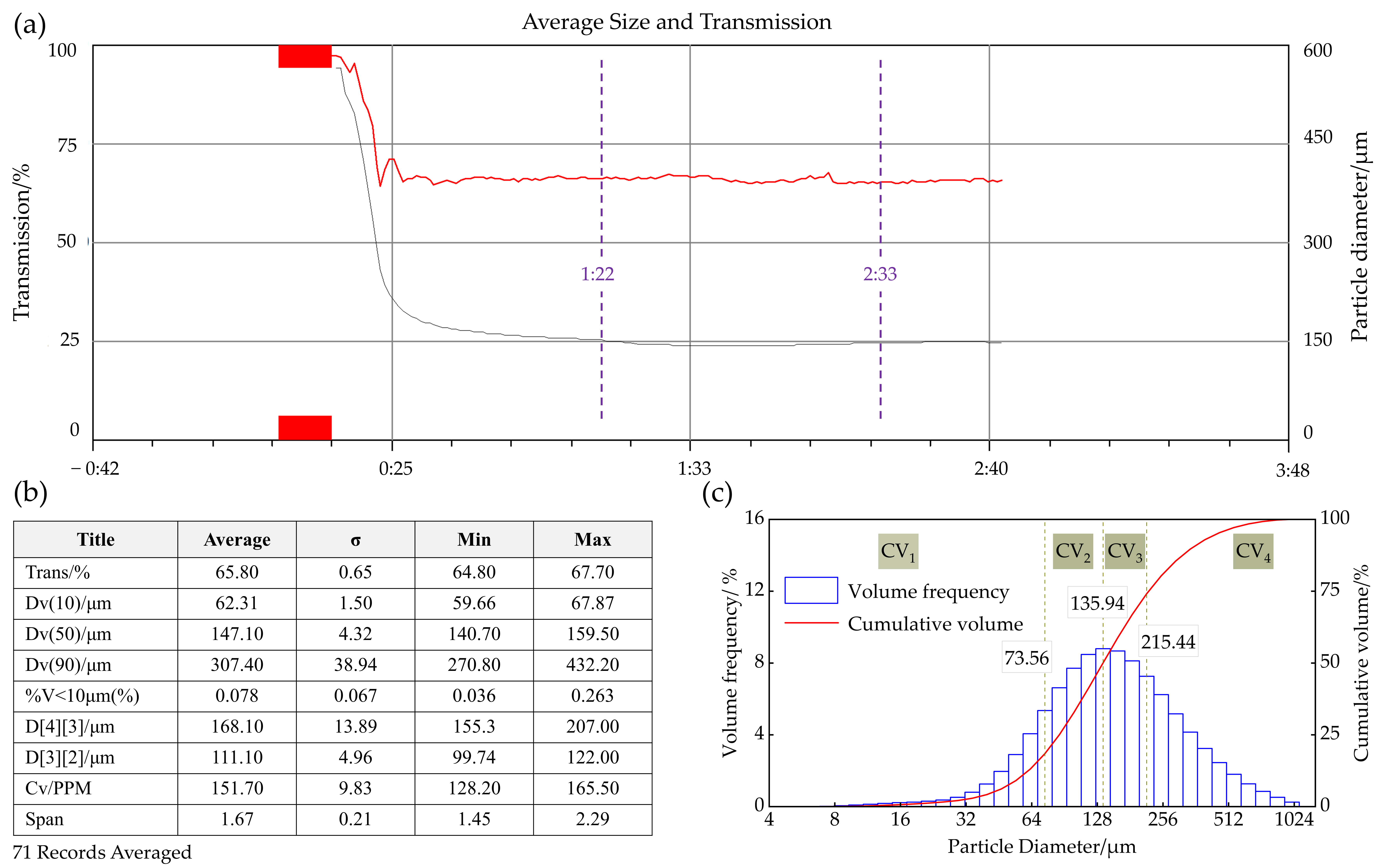
Figure 4 illustrates the experimental data processing procedure. To ensure the accuracy of the measured atomization parameters in the downstream region, the variation curves of laser transmittance and droplet diameter were used as validity criteria. The laser transmittance corresponds to the red curve in Figure 4a, and the droplet diameter corresponds to the black curve. Measured data were judged as reliable when both curves remained relatively stable on the software interface. Data within the stable period were selected for analysis. The atomization parameters during this period were calculated using the weighted average method via the Malvern Spraytec software (Version 3.20). Figure 4b presents the weighted average results calculated from the data in Figure 4a (from 1.22 s to 2.33 s), including characteristic diameter, mean diameter, and DPF. From Figure 4b, D[3][2] is the sauter mean diameter (SMD), and Cv is the dispersed phase fraction (DPF).
Specifically, the DPF values are obtained directly from the Malvern Spraytec software, which reports this parameter as the volume concentration Cv. The volume concentration is calculated from the measured laser transmission based on the Beer-Lambert law and is natively expressed in parts per million (PPM). One PPM corresponds to 1 µL of droplet volume per liter of gas, or equivalently, a volume fraction of 10−6. DPF represents the total droplet volume per unit volume of gas, thus directly reflecting the spatial density of droplets in the spray field.
Furthermore, to reveal the relationship between the characteristic droplet size (SMD) and droplet size distribution, the droplet size distribution was divided into four intervals, and their cumulative volumes were calculated and denoted as CV1, CV2, CV3, and CV4, as shown in Figure 4c. The corresponding size boundaries (unit: μm) are: CV1: (0, 73.56], CV2: (73.56, 135.94], CV3: (135.94, 215.44], and CV4: (215.44, 1000].

2.4. Droplet Motion and Breakup Theory in the Downstream Region

Based on the primary breakup theory of hydraulic nozzles, analyzing the correlation between droplet velocity decay and travel distance is essential to uncover the dependence of droplet size on co-flow disturbance in the downstream region of the droplet field. Studies have demonstrated that a pressure-driven liquid jet, upon exiting the nozzle orifice into ambient air, forms a continuous thin liquid film in the gas phase. Due to the significant velocity difference between the liquid film and the surrounding gas, gas-phase shear forces and ambient perturbations gradually induce characteristic-mode oscillatory waves on the film surface. As the wave amplitude amplifies progressively along the direction of film propagation, the liquid film undergoes necking and fragmentation, subsequently disintegrating into slender ligaments and large-scale droplets [25]. In this context, the droplet velocity at the hydraulic nozzle outlet can be formulated as follows [28,29,30]:
U d 0 = k u 2 P ρ u
where P is the water supply pressure, Pa; ρ u is the water density, kg/m3; ku stands for the dimensionless wave number for the most unstable disturbance in the liquid sheet constrained by the LISA model, which is expressed as follows [29,30]:
k u = max   [ 0.7 , 4 Q ρ u π d n 2 cos θ 2 P ]
where Q is the mass flow rate, kg/s; θ is the half of the spray angle, °; dn is the nozzle outlet diameter, mm.
The velocity of a single droplet in the co-flow disturbance airflow is described by a modified exponential decay model, derived from Newton’s drag law and the droplet motion equation, as follows:
U d x = U g + U d 0 U g e - 3 C d ρ a 4 ρ u d f   ·   U d 0 U d 0 - U g   ·   x
where Ug is the co-flow disturbance velocity, m/s; Udo is the initial droplet velocity, m/s; df is the droplet diameter, m; ρ a is the density of disturbance airflow, kg/m3; Cd is the dimensionless drag coefficient. Within the range of droplet Reynolds numbers Re from 1 to 1000 investigated in this work, the drag coefficient Cd equation for spherical liquid droplets is expressed as follows [31,32]:
C d   =   24 R e   1 + 0.15   Re 0.687
The Reynolds number is defined as follows:
R e   =   ρ a   d f   ( U d 0   U g ) μ a
where μa is the dynamic viscosity of disturbance airflow, Pa/s.
For droplets moving in co-flow, the aerodynamic drag force induced by the airflow tends to deform and break up the droplets, whereas the surface tension resists such deformation and restores them to a spherical shape. Accordingly, the dimensionless Weber number serves as a key criterion for determining whether the airflow can break up the droplets, and its expression is given as follows [1,18]:
W e   =   ρ a U d ( x )   U g 2 d f σ
where σ is the surface tension of droplets, N/m.

3. Results and Discussion

3.1. Theoretical Analysis of Droplet Motion and Breakup

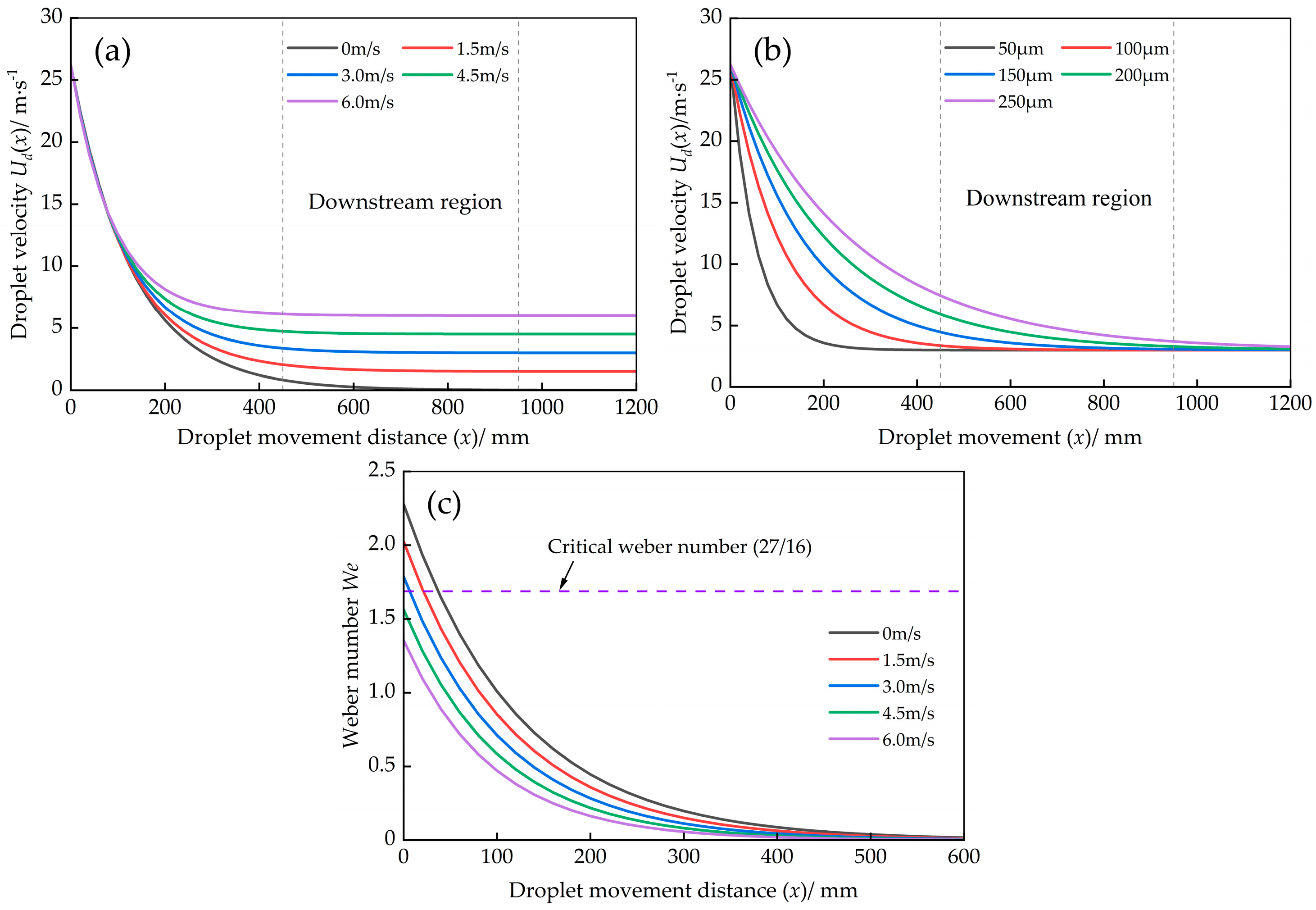
The experimental parameters are substituted into Equations (1)–(6) for numerical analysis. Figure 5 presents the schematic diagram showing the relationships among the velocity decay of a single droplet, the Weber number, and the droplet travel distance. As shown in Figure 5, three distinct laws can be summarized as follows: (1) When the droplet diameter is constant, the greater the co-flow disturbance velocity, the shorter the travel distance required for the droplet velocity to decay to the co-flow disturbance velocity. Compared with the condition without co-flow disturbance, the droplet velocity at the same travel distance increases with the enhancement of co-flow disturbance intensity, but the increase is less than 1%, indicating that the effect of co-flow disturbance on improving droplet velocity is negligible relative to the surrounding environment. (2) At a fixed co-flow disturbance intensity, the rate of droplet velocity decay decreases with increasing diameter, indicating that smaller droplets reach the disturbance velocity over a shorter travel distance. (3) According to the Kelvin–Helmholtz instability theory, under co-flow disturbance, the aerodynamic Weber number of droplets decreases with increasing disturbance velocity. Within the range of experimental conditions investigated in this study, the Weber number remains well below the critical value (27/16) for droplet breakup. This indicates that the observed variation in droplet diameter within the downstream region is not primarily caused by droplet breakup.
Furthermore, when the motion and breakup characteristics of a single droplet are extended to the entire droplet group in the downstream region, it can be concluded that the co-flow disturbance exerts a velocity coordination effect. Specifically, co-flow disturbance drives the overall velocity of the droplet group to gradually approach the co-flow velocity, and this coordination effect is likely a major contributor to the observed droplet size variation in the downstream region.

3.2. Sauter Mean Diameter

Table 1 shows the SMD values at the six measurement points under different co-flow disturbance intensities. Under the same water supply pressure, the hollow cone nozzle achieves the smallest SMD in the downstream region, indicating the best atomization performance among the three nozzles. The SMD variations with co-flow disturbance velocity do not follow a consistent trend across the three nozzles. This is reflected in two aspects: (1) The SMD trends with co-flow disturbance velocity differ significantly among the measurement points. For example, for the solid cone nozzle, the SMD at point B decreases continuously as velocity increases, whereas the SMD at point C first decreases and then increases. (2) At the same co-flow disturbance velocity, the SMD trend varies with the measurement point location along the downstream direction. For the solid square-cone nozzle, at a co-flow disturbance velocity of 1.5 m/s, the SMD at the six points decreases gradually with increasing distance. However, when the velocity was increased to 4.5 m/s, the SMD first decreased and then increased along the downstream direction.
Overall, co-flow disturbance velocity changes the SMD of droplets in the downstream region of the spray field for all three tested nozzles, and the SMD at most measuring points is reduced. The maximum reduction rates of SMD for the solid cone nozzle, solid square-cone nozzle, and hollow cone nozzle are 21.2%, 24.8%, and 7.9%, respectively.
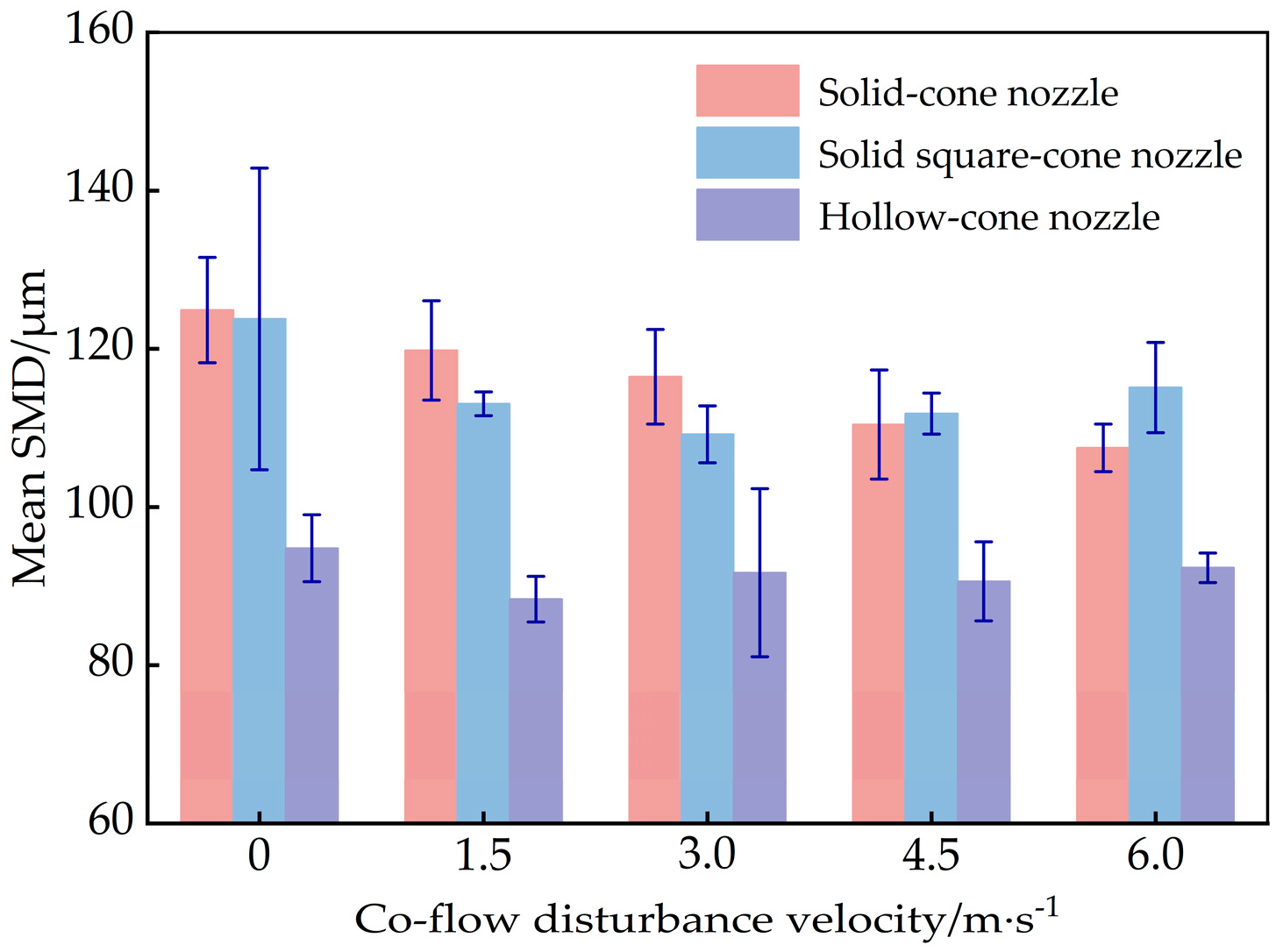
To reveal the mechanism of SMD variation in the downstream region under different co-flow disturbance intensities, and to evaluate its effect on the SMD across the entire downstream region, the mean and standard deviation of SMD at six measurement points were calculated for each co-flow disturbance velocity condition. The results are shown in Figure 6.
As observed in Figure 6, the mean SMD values of the three tested nozzles under four co-flow disturbance conditions are all smaller than those under the undisturbed condition. This indicates that the reduction in mean SMD induced by co-flow disturbance in the downstream region is a consistent trend in the present study. Specifically, the mean SMD of the hollow-cone nozzle decreases monotonically with increasing co-flow disturbance velocity. The mean SMD of the solid square-cone nozzle first decreases and then slightly increases with rising co-flow disturbance velocity. Similarly, that of the solid-cone nozzle decreases initially and then tends to stabilize. Combined with the previous theoretical analysis, these results suggest that the reduction in mean SMD within the downstream region is not primarily caused by droplet breakup, even though co-flow disturbance lowers the Weber number of moving droplets. Instead, the velocity coordination effect of co-flow disturbance on the droplet group appears to dominate droplet collision and coalescence.
Theoretically, the reduction in mean SMD under co-flow disturbance can be attributed to a velocity coordination effect. The co-flow drives the overall velocity of the droplet group toward the co-flow disturbance velocity, reducing the relative velocity between individual droplets. This suppresses droplet collision and coalescence, ultimately leading to a smaller mean droplet size. This mechanism is consistent with the experimental data in Table 1. Specifically, the SMD decreases under co-flow disturbance, yet the variation pattern is not strictly linear across different nozzles and measurement positions. In contrast, the droplet breakup induced by aerodynamic forces is unlikely to be the dominant mechanism in the present study. Aerodynamic droplet breakup occurs when the aerodynamic force exceeds the surface tension force. The surface tension force tends to maintain the droplet in a spherical shape. This condition is characterized by the Weber number exceeding a critical threshold. Since the co-flow is aligned with the droplet movement direction, the relative velocity between the droplet and the airflow decreases with increasing co-flow disturbance intensity, which in turn lowers the Weber number. According to the Kelvin–Helmholtz instability theory and the critical Weber number criterion, the Weber number under the present experimental conditions is far below the threshold for droplet breakup. Therefore, the observed SMD reduction is primarily governed by the velocity coordination effect of co-flow disturbance on droplet motion.
The above interpretation is established based on the theoretical analysis of droplet motion and breakup in the downstream region of the droplet field, which inevitably brings certain experimental limitations. In future research, advanced velocity measurement techniques such as Phase Doppler Anemometry (PDA) and Particle Image Velocimetry (PIV) can be adopted for further experimental verification.

3.3. Particle Size Distribution

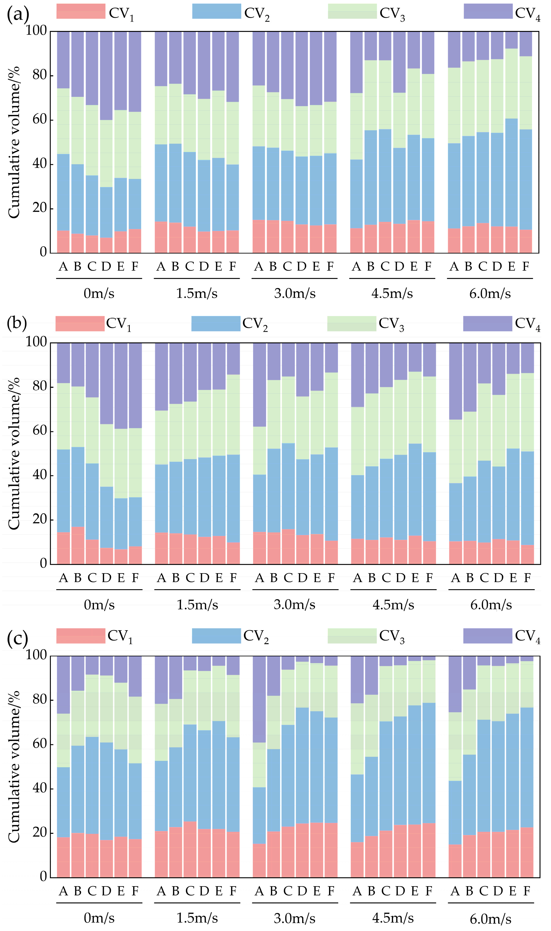
To explore the mechanism behind the co-flow disturbance-induced reduction in SMD in the downstream region, the synergistic response of the droplet size distribution was examined. Figure 7 presents the segmented statistical result of droplet size distribution for each experimental condition.
As illustrated in Figure 7, the influence of co-flow disturbance on the cumulative volumes of CV1, CV2, CV3, and CV4 is evident. Specifically, for the solid-cone nozzle, compared with the condition without co-flow disturbance, the four co-flow velocities (1.5, 3.0, 4.5, and 6.0 m/s) caused notable changes in the cumulative volumes. At the six measuring points, the total cumulative volume of CV1 and CV2 increased, while that of CV3 and CV4 decreased. Taking measuring point D as an example, as the co-flow disturbance velocity increases from 0 to 6.0 m/s, the total cumulative volume of CV1 and CV2 increases from 29.85% to 54.41%, while the corresponding SMD decreases from 132.2 μm to 104.4 μm. For the solid square-cone nozzle and hollow-conical nozzle, the four co-flow velocities (1.5, 3.0, 4.5, and 6.0 m/s) caused a notable increase in the total cumulative volume of CV1 and CV2 at measuring points C, D, E, and F. However, the total cumulative volume of CV3 and CV4 also increased at measuring points A and B. Taking the solid square-cone nozzle as an example, as the co-flow disturbance velocity increases, the total cumulative volumes of CV3 and CV4 at the measuring point A are 47.95%, 54.72%, 59.14%, 59.50%, and 63.07%, respectively, and the corresponding SMDs are 102.6 μm, 114.5 μm, 107.9 μm, 113.3 μm, and 118.1 μm, respectively. These observations indicate that the reduction in mean SMD under co-flow disturbance is accompanied by an increase in the cumulative volumes of CV1 and CV2, and a decrease in those of CV3 and CV4. Since the sum of the cumulative volumes of CV1, CV2, CV3, and CV4 is equal to 100%, the increase in the fine-droplet volume frequency necessarily corresponds to a decrease in the coarse-droplet volume frequency.
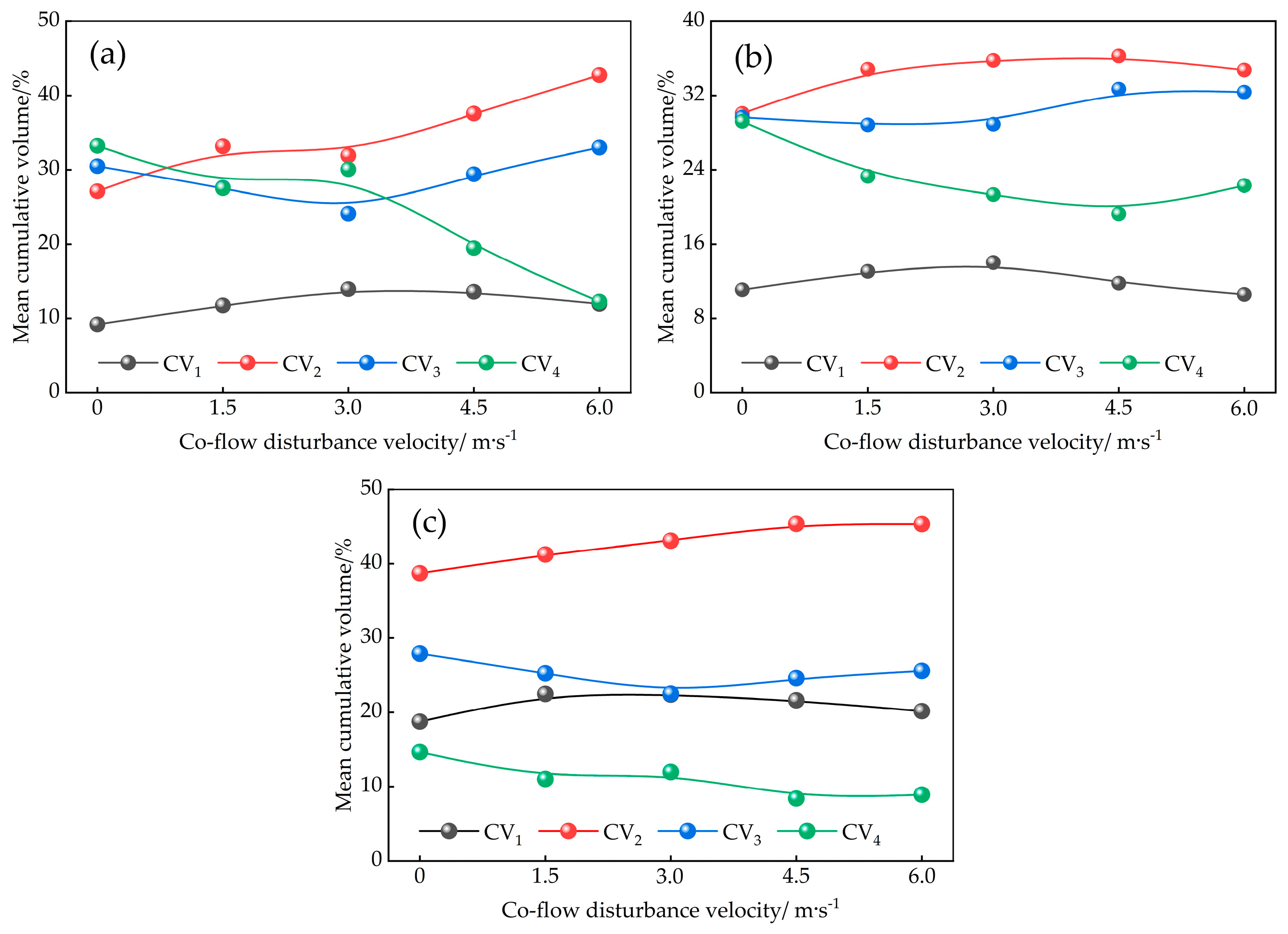
The experimental results above show that the mean SMD of the solid square-cone nozzle and the hollow-cone nozzle exhibits a trend of first decreasing and then increasing with increasing co-flow disturbance velocity. To further investigate the velocity inflection point corresponding to this trend, the mean values of the four cumulative volumes (CV1, CV2, CV3, and CV4) at the six measurement points under each co-flow disturbance velocity condition were calculated, and the results are presented in Figure 8. It should be noted that the sum of the mean cumulative volumes of CV1, CV2, CV3, and CV4 is equal to 100%.
As shown in Figure 8, with the co-flow disturbance velocity increase, the mean cumulative volumes of CV1, CV2, CV3, and CV4 for each of the three hydraulic nozzles exhibit two pairs of mirror-symmetric relationships. Specifically, CV1 mirrors CV3, and CV2 mirrors CV4. At co-flow disturbance velocities below 3 m/s, the three hydraulic nozzles exhibit a consistent trend in the mean cumulative volumes. The mean cumulative volumes of CV1 and CV2 increase, while those of CV3 and CV4 decrease, indicating a shift from the coarse-droplet volume frequency to the fine-droplet volume frequency. This feature directly explains the reduction in mean SMD within this velocity range. When the co-flow disturbance velocity exceeds 3 m/s, the mean cumulative volumes of CV1 and CV3 for the three hydraulic nozzles exhibit opposite trends. CV3 increases while CV1 decreases, which indicates that an increase in co-flow disturbance velocity leads to a shift in the mean cumulative volume from fine-droplet fractions to coarse-droplet fractions. Taking the solid square-cone nozzle as an example, at a co-flow velocity of 3 m/s, the mean cumulative volumes of CV1, CV2, CV3, and CV4 are 14.01%, 35.78%, 28.90%, and 21.31%, respectively, with a corresponding mean SMD of 109.2 μm. At a co-flow velocity of 6 m/s, these values are 10.56%, 34.75%, 32.38%, and 22.30%, respectively, with a corresponding mean SMD of 115.1 μm. This variation further confirms the above trend.
In summary, co-flow disturbance redistributes the droplet size distribution in the downstream region, which in turn results in variations in the SMD. For the solid square-cone and hollow-conical nozzles, the co-flow disturbance velocity of 3 m/s marks the inflection points of the cumulative volume trends. Beyond this velocity, further increases in co-flow disturbance velocity do not lead to a further reduction in the mean SMD.

3.4. Dispersed Phase Fraction

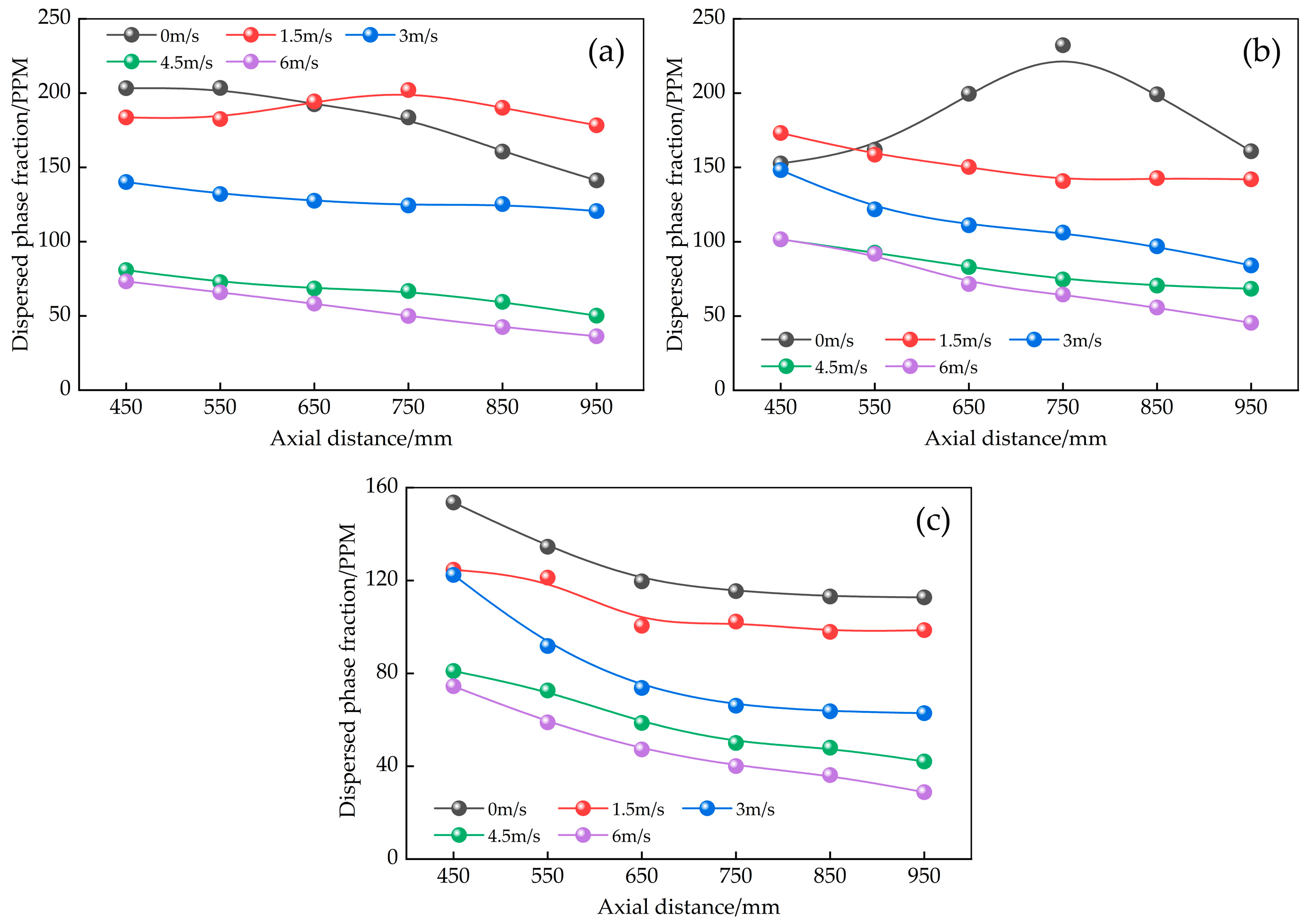
Figure 9 shows the variation pattern of the DPF at six measurement points for the three hydraulic nozzles under five co-flow disturbance conditions. In the absence of co-flow disturbance, the DPF of the solid-cone and hollow-cone nozzles decreases with increasing axial distance, with the maximum value at measuring point A, indicating that the droplet volume concentration decreases as the distance from the nozzle increases. In contrast, the DPF of the solid square-cone nozzle exhibits a trend of first increasing and then decreasing along the axial distance. The DPF values at the six measuring points are 152.7, 161.9, 199.6, 232.2, 199.2, and 160.9 PPM, respectively, with the peak value occurring at point D. When the co-flow disturbance velocity increases from 0 to 1.5 m/s, the DPF of the solid conical nozzle at measuring points D, E, and F increases by 18.5, 29.5, and 37.1 PPM, respectively. The standard deviation calculated from all six measuring points decreases from 25.07 to 8.79, indicating that a moderate disturbance velocity is beneficial for improving the uniformity of DPF distribution in the downstream region. Overall, the DPF of the three nozzles in the downstream region exhibits a decreasing trend with increasing axial distance. Co-flow disturbance generally reduces the DPF in the downstream region. For the solid-conical nozzle, a moderate increase in co-flow disturbance velocity contributes to a more uniform DPF distribution.
To further compare the effects of co-flow disturbance on SMD and DPF in the downstream region of the droplet field, the mean values of SMD and DPF were calculated based on the measurement data from six measuring points in the downstream region. The relative reduction rates (REA) of mean SMD and mean DPF under four disturbance velocities, relative to the static condition, are presented in Table 2. Specifically, the reference condition for the REA is the case with a co-flow disturbance velocity of 0 m/s.
As shown in Table 2, the relative reduction rate of the mean DPF is considerably higher than that of the mean SMD. For example, for the hollow-cone nozzle, under four co-flow disturbance velocities (1.5, 3.0, 4.5, and 6.0 m/s), the relative reduction rates of mean SMD are 6.77%, 3.27%, 4.42%, and 2.60%, respectively, while those for mean DPF are 13.86%, 35.85%, 52.88%, and 61.86%, respectively. In engineering applications such as dust suppression, cooling, and waste heat recovery, hydraulic nozzles are generally required to produce a small SMD and a high DPF, since a higher DPF indicates a greater droplet concentration per unit volume, which enhances heat and mass transfer efficiency. However, the co-flow disturbances commonly present in these engineering scenarios pose a challenge to meet this requirement. The experimental results of this study show that controlling the co-flow disturbance velocity within a reasonable range can simultaneously reduce SMD and improve the uniformity of DPF distribution. Taking the solid-cone nozzle as an example, when the co-flow disturbance velocity is controlled at 1.5 m/s, the mean SMD in the downstream region decreases by 4.08%, while the mean DPF increases by 4.27%, indicating that this velocity is a favorable control condition for this nozzle. In contrast, for the solid square-cone and hollow conical nozzles, when the disturbance velocity exceeds 3 m/s, the relative reduction rate of the mean SMD gradually decreases, while the relative reduction rate of the mean DPF exceeds 35.00%, indicating that excessive disturbance velocity has a more pronounced negative effect on DPF.

4. Conclusions and Outlook

4.1. Conclusions

This study experimentally investigated the effects and mechanisms of co-flow disturbance on the atomization characteristics of the downstream region in the droplet field of hydraulic nozzles. The main conclusions are as follows:
(1)
Theoretical analysis shows that the velocity coordination effect of co-flow disturbance reduces the relative velocity between droplets in the downstream region, thereby suppressing collision-induced coalescence. In addition, the calculated Weber numbers are well below the critical breakup threshold, excluding aerodynamic breakup as the primary cause of the SMD reduction. Therefore, the observed SMD decrease is mainly attributable to the velocity coordination effect rather than droplet breakup.
(2)
The co-flow disturbance exerts a significant regulatory effect on the mean SMD in the downstream region, and the responses vary notably among different nozzle types. For the solid-cone nozzle, the mean SMD decreases from 124.9 μm to 107.5 μm with increasing co-flow velocity. In contrast, for the solid square-cone and hollow-cone nozzles, the mean SMD first decreases and then slightly increases, with 3.0 m/s identified as the inflection point.
(3)
The co-flow disturbance redistributes the droplet size distribution. Specifically, the total cumulative volumes of CV1 and CV2 (0–135.94 μm) increase, while those of CV3 and CV4 (135.94–1000 μm) decrease, thereby reducing the mean SMD. As the co-flow disturbance velocity increases from 0 to 6.0 m/s, the total cumulative volume of CV1 and CV2 increases from 29.85% to 54.41%, while the corresponding SMD decreases from 132.2 μm to 104.4 μm (e.g., solid-cone nozzle).
(4)
The DPF response to co-flow disturbance is more sensitive than that of SMD. At a low disturbance velocity of 1.5 m/s, the solid-cone nozzle achieves a dual optimization of SMD reduction (by 4.08%) and DPF enhancement (by 4.27%). However, when the disturbance velocity exceeds 3 m/s, the relative reduction rates of DPF for the solid square-cone and hollow-cone nozzles both exceed 35%, indicating that excessive disturbance velocity has a pronounced negative effect on DPF.

4.2. Outlook

This paper has investigated the atomization characteristics of the downstream region under co-flow disturbance. However, the current study still has certain shortcomings and limitations, mainly including the following aspects:
(1)
Theoretical analysis and experimental results suggest that the velocity coordination effect of co-flow disturbance is the primary cause of SMD reduction in the downstream region. Without direct velocity measurements, however, this conclusion remains tentative. Future work will use PDA and PIV to validate this mechanism and extend the research to more complex flow fields and practical engineering conditions.
(2)
This study systematically investigated the effects of different disturbance velocities on the atomization performance of hydraulic nozzles, but did not consider variations in water supply pressure. On this basis, future work will extend the water pressure range and further examine the influence of co-flow disturbance on droplet fields with smaller droplet sizes, so as to validate and extend the applicability of the present conclusions.

Author Contributions

Methodology, Z.W. and C.L.; investigation, Z.W. and S.C.; data curation, W.L.; writing—original draft, Z.W.; writing—review and editing, Y.C.; supervision, C.L.; funding acquisition, Z.W. and Y.C. All authors have read and agreed to the published version of the manuscript.

Funding

This research was funded by Guangxi Natural Science Foundation (2025GXNSFBA069482, 2026GXNSFHA00640246) and Basic Ability Improvement Project for Young and Middle-Aged Teachers of the Education Department in Guangxi (2025KY0824), China.

Data Availability Statement

The original contributions presented in this study are included in the article. Further inquiries can be directed to the corresponding author.

Conflicts of Interest

The authors declare no conflicts of interest.

References

  1. Liu, F.; Nie, W.; Peng, H.; Xu, C.; Guo, L.; Niu, W.; Peng, Y.; Wang, Y. Characteristics of internal and external flow fields and the atomization mechanism of air-assisted atomizing nozzles determined by large eddy simulation and experiments. Energy 2025, 337, 138383. [Google Scholar] [CrossRef]
  2. Lu, X.; Xiao, J.; Miao, J.; Chen, Z.; Wang, S. Study on the mining dust release behavior under the top coal continuous caving coupling the dynamic hydraulic support advancing. Process Saf. Environ. Prot. 2025, 195, 106755. [Google Scholar] [CrossRef]
  3. Shu, H.; Li, N.; Dong, L.; Luo, Q.; Sabao, A.R. Thermal humidity risk assessment in high-temperature environment of mines based on uncertainty measurement theory. Case Stud. Therm. Eng. 2023, 50, 103401. [Google Scholar] [CrossRef]
  4. Yu, H.; Zahidi, I. Environmental hazards posed by mine dust, and monitoring method of mine dust pollution using remote sensing technologies: An overview. Sci. Total Environ. 2023, 864, 161135. [Google Scholar] [CrossRef] [PubMed]
  5. Lin, L.; Huo, Y.; Tian, L.; Liu, Y.; Song, Y.; Hu, U.; Liu, M.; Yang, G.; Gao, Y.; Liu, W.; et al. Emission Characteristics and Suppression Measures of Dust from Open-Pit Coal Mine: A Review. Energy Fuels 2026, 40, 7839–7861. [Google Scholar] [CrossRef]
  6. Xin, S.; Han, X.; Sun, Q.; Li, M.; Wu, Y.; Zhang, Z.; Yang, W. Numerical studies on the effects of the hybrid cooling and dust suppression solution in hot fully-mechanized mining face. Int. J. Refrig. 2024, 166, 73–83. [Google Scholar] [CrossRef]
  7. Jin, L.; Liu, J.; Lin, Q.; Zhou, Y.; Li, G.; Wang, S.; Wei, Y.; Ou, S.; Wang, T.; Wang, J. Review on the research and application of water spray dust-reduction technology in mines. Metal. Mine 2023, 07, 2–17. [Google Scholar] [CrossRef]
  8. Wang, H.; Wu, Z.; Chen, S.; Wang, P.; Huang, M. Experimental study and efficiency optimization on water film dust removal of wet chord grid. J. China Coal Soc. 2023, 48, 279–289. [Google Scholar] [CrossRef]
  9. Zhang, C.; Yuan, S.; Zhang, N.; Li, C.; Li, H.; Yang, W. Dust-suppression and cooling effects of spray system installed between hydraulic supports in fully mechanized coal-mining face. Build. Environ. 2021, 204, 108106. [Google Scholar] [CrossRef]
  10. Wu, G.; Wang, P.; Li, Y.; Chen, Y.; Li, S. Structural optimization of a magnetized water spray dust reduction device based on orthogonal experimental design. J. Clean. Prod. 2026, 553, 147993. [Google Scholar] [CrossRef]
  11. Wang, H.; Du, Y.; Wei, X.; He, X. An experimental comparison of the spray performance of typical water-based dust reduction media. Powder Technol. 2019, 345, 580–588. [Google Scholar] [CrossRef]
  12. Zhang, T.; Tao, S.; Ge, S.; Li, S.; Wang, C.; Mu, X.; Guo, Y. Study on structure optimization of supersonic aerodynamic spray device and synergistic control effect of dust and noise. J. China Coal Soc. 2025, 50, 2540–2549. [Google Scholar] [CrossRef]
  13. Zhang, T.; Mu, X.; Jing, D.; Ge, S.; Meng, X.; Zhao, S.; Zhang, X. Influence of aerodynamic pressure on dust removal by supersonic siphon atomization. Energy 2023, 282, 128727. [Google Scholar] [CrossRef]
  14. Fang, X.; Jiang, B.; Yuan, L.; Liang, Y.; Ren, B.; Tao, W.; Li, X. Experimental study on atomization characteristics of gas–liquid two-phase flow nozzle and Its dust removal effect. Materials 2022, 15, 565. [Google Scholar] [CrossRef] [PubMed]
  15. Wang, J.; Xu, C.; Zhou, G.; Zhang, Y. Spray structure and characteristics of a pressure-swirl dust suppression nozzle using a phase doppler particle analyze. Processes 2020, 8, 1127. [Google Scholar] [CrossRef]
  16. Jia, B.; Chao, Y.; Wang, J.; Jin, Q.; Leng, H.; Su, Y.; Gong, J.; Yu, Z.; Yu, Y.; Wu, Y. Atomization characteristics of gas–liquid internal mixing of non-Newtonian fluids. Phys. Fluids 2025, 37, 113107. [Google Scholar] [CrossRef]
  17. Han, Q.; Zhang, D.; Liu, X.; Sun, B.; He, X.; Shen, L.; Song, S. Experimental study on atomization characteristics of swirl nozzle under annular airflow impingement. Fluids 2024, 9, 80. [Google Scholar] [CrossRef]
  18. Xie, Z.; Zhao, Z.; Long, B.; Xiao, Y.; Wu, H. Atomization characteristics and axis correction coefficient of pressure atomizing nozzle for coal dust control. Build. Environ. 2025, 284, 113530. [Google Scholar] [CrossRef]
  19. Barbieri, M.R.; Achelis, L.; Fritsching, U. Effect of Y-jet nozzle geometry and operating conditions on spray characteristics and atomizer efficiency. Int. J. Multiph. Flow 2023, 168, 104585. [Google Scholar] [CrossRef]
  20. Shao, W.; Wang, S.; Wang, W.; Shao, K.; Xiao, Q.; Cui, Z. Experiment and Simulation on a Refrigeration Ventilation System for Deep Metal Mines. Sustainability 2023, 15, 7818. [Google Scholar] [CrossRef]
  21. Mo, J.; Ma, W. Researches on the numerical simulation of the dust pollution characteristics and the optimal dust suppression wind-speed on fully mechanised caving face. Energy Explor. Exploit. 2022, 40, 800–815. Available online: https://doi.org/10.1177/01445987211055807. [CrossRef]
  22. Wu, Z.; Wang, H.; Guo, H.; Gu, M.; Jiang, J.; Chen, S.; Huang, J.; Fan, S. Experimental investigation and application of mine airflow purification and reuse technology. Environ. Technol. Innov. 2021, 24, 102035. Available online: https://doi.org/10.1016/j.eti.2021.102035. [CrossRef] [PubMed]
  23. Sun, B.; Liu, C.; Yao, J.; Zhou, G.; Jia, J.; Liu, Z. Study on the nozzle high-pressure atomization characteristics and the influencing factors of fust mist coagulation under multi-factor perturbation conditions. Water Air Soil Pollut. 2026, 237, 240. [Google Scholar] [CrossRef]
  24. Qiu, H.; Zhu, L.; Fan, Q. Experiment on distribution of particle size and velocity in spray field under disturbance of airflow. Saf. Coal Mines 2016, 47, 20–23. [Google Scholar] [CrossRef]
  25. Nie, W.; Cheng, W.; Zhou, G.; Xie, J.; Cui, X. Experimental study on atomized particle size as affected by co-flow disturbance at the heading face. J. China Univ. Min. Technol. 2012, 41, 378–383. [Google Scholar]
  26. Li, H.; Xiao, L.; Wang, S.; Ren, G. Atomization Performance of Spray Nozzles and Their Influence on Fine Particle Collection in the Wet Electrostatic Precipitator. Coatings 2024, 14, 1599. [Google Scholar] [CrossRef]
  27. Huang, M.; Jin, H.; Li, C.; Xu, A.; Hao, X.; Chen, S. Investigation of the heat transfer characteristics of a combined spray and chord grille water film. Int. J. Therm. Sci. 2026, 220, 110417. [Google Scholar] [CrossRef]
  28. Chen, S.; Liu, C.; Wu, Z.; Yu, Q. Effects of co-current airflow on water atomization in a curved diffuser. Energy Explor. Exploit. 2021, 39, 657–668. [Google Scholar] [CrossRef]
  29. Schmidt, D.P.; Nouar, I.; Senecal, P.K.; Rutland, J.; Martin, J.K.; Reitz, R.D.; Hoffman, J.A. Pressure-Swirl Atomization in the Near Field. SAE Trans. 1999, 108, 471–484. [Google Scholar]
  30. Senecal, P.K.; Schmidt, D.P.; Nouar, I.; Rutland, C.J.; Reitz, R.D.; Corradini, M.L. Modeling high-speed viscous liquid sheet atomization. Int. J. Multiphas. Flow 1999, 25, 1073–1097. [Google Scholar] [CrossRef]
  31. Chen, Y.; Wang, L.; Chang, H.; Zhang, Q. A review of drag coefficient models in gas-liquid two-phase flow. Chem. Bio. Eng. 2022, 3, 311–325. [Google Scholar] [CrossRef]
  32. Li, H.; Wang, K.; Zhang, J. Verification and analysis of a new drag model based on bubbling fluidized bed. J. Chin. Soc. Power Eng. 2022, 48, 715–721. [Google Scholar] [CrossRef]
Figure 1. Experimental system.
Processes 14 02206 g001
Figure 2. Hydraulic nozzles used in the experiment. (a) Solid-cone nozzle; (b) Solid square-cone nozzle; (c) Hollow-cone nozzle.
Processes 14 02206 g002
Figure 3. Measurement point arrangement. (a) Distribution of laser in the downstream region of droplet field; (b) Testing points in the downstream region of droplet field.
Processes 14 02206 g003
Figure 4. Experimental data processing. (a) Measurement time period selected for data analysis; (b) Weighted average results; (c) Segmental statistics of cumulative volume.
Processes 14 02206 g004
Figure 5. Relationship between velocity decay, Weber number, and droplet movement distance of a single droplet. (a) df = 100 μm, ρ a   =   1.203 kg/m3; (b) Ug = 3 m/s; (c) df = 200 μm, σ = 0.07275.
Processes 14 02206 g005
Figure 6. Relationship between the mean SMD ± SD and co-flow disturbance velocity.
Processes 14 02206 g006
Figure 7. Relationship between co-flow disturbance velocity and cumulative volume of CV1, CV2, CV3, and CV4 at the six measuring points. (a) Solid-cone nozzle; (b) Solid square-cone nozzle; (c) Hollow-cone nozzle.
Processes 14 02206 g007
Figure 8. Relationship between co-flow disturbance velocity and mean cumulative volume of CV1, CV2, CV3, and CV4. (a) Solid-cone nozzle; (b) Solid square-cone nozzle; (c) Hollow-cone nozzle.
Processes 14 02206 g008
Figure 9. Dispersed phase fraction distribution along the axial direction under different co-flow disturbance velocities. (a) Solid-cone nozzle; (b) Solid square-cone nozzle; (c) Hollow-cone nozzle.
Processes 14 02206 g009
Table 1. The SMD of the six measuring points under different co-flow disturbance intensities.
Nozzle TypeVelocity/m·s−1Measuring Point
ABCDEF
Solid-cone nozzle0121.4127.7132.0132.2119.6116.5
1.5112.3112.3120.0127.0122.2125.0
3.0108.6111.0114.5121.0123.5120.2
4.5119.6109.8101.5117.3105.5108.9
6.0113.2106.1107.3104.4106.6107.3
Solid square-cone nozzle0102.6101.4117.7139.9142.5138.6
1.5114.5113.0115.0112.8111.9111.1
3.0107.9106.3104.2112.4111.1113.2
4.5113.3111.5110.5109.4109.9116.3
6.0118.1123.5115.8115.4107.2110.6
Hollow-cone nozzle0102.893.7290.895.793.292.6
1.590.690.1282.887.988.989.9
3.0112.593.087.786.686.284.2
4.597.695.390.486.087.486.5
6.094.794.2991.692.391.489.7
Table 2. Relative reduction rates of mean SMD and mean DPF for different nozzle types under various co-flow disturbance velocities.
Velocity
/m·s−1
Nozzle Type
Solid-Cone NozzleSolid Square-Cone NozzleHollow-Cone Nozzle
SMD
/μm
REA
/%
DPF
/PPM
REA
/%
SMD
/μm
REA
/%
DPF
/PPM
REA
/%
SMD
/μm
REA
/%
DPF
/PPM
REA
/%
0124.90180.78123.78 184.4294.79124.82
1.5119.804.08%188.50−4.27%113.058.67%151.2817.97%88.376.77%107.5213.86%
3.0116.476.75%128.3029.03%109.1811.80%111.3839.61%91.693.27%80.0735.85%
4.5110.4311.59%66.3863.28%111.819.67%81.7955.65%90.604.42%58.8252.88%
6.0107.4813.95%54.3569.94%115.107.01%77.0558.22%92.332.60%47.6161.86%
Disclaimer/Publisher’s Note: The statements, opinions and data contained in all publications are solely those of the individual author(s) and contributor(s) and not of MDPI and/or the editor(s). MDPI and/or the editor(s) disclaim responsibility for any injury to people or property resulting from any ideas, methods, instructions or products referred to in the content.