Review

A Review of Research on the Intelligent Design of Ferrofluid Seals for Ultra-High Vacuum Applications


1
School of Energy and Electrical Engineering, Qinghai University, Xining 810016, China
2
School of Engineering, Qinghai Institute of Technology, Xining 810016, China
3
School of Energy and Power Engineering, Lanzhou University of Technology, Lanzhou 730050, China
4
Key Laboratory of Fluid and Power Machinery of Ministry of Education, Xihua University, Chendu 610039, China
*
Author to whom correspondence should be addressed.
Processes 2026, 14(13), 2171; https://doi.org/10.3390/pr14132171
Submission received: 20 April 2026 / Revised: 25 June 2026 / Accepted: 1 July 2026 / Published: 3 July 2026
(This article belongs to the Section Chemical Processes and Systems)

Abstract

Ferrofluid sealing is an important non-contact sealing technology for ultra-high vacuum (UHV) equipment, but its reliability is affected by more than pressure-bearing capacity alone. This review shows that carrier-liquid evaporation, material outgassing, thermal degradation, magnetic-field distortion, and liquid-ring instability are the main factors limiting UHV ferrofluid seals. Multiphysics simulation and parametric optimization remain the most mature tools for analyzing magnetic-field distribution, pressure resistance, temperature rise, and structural deformation. Data-driven condition identification improves failure monitoring, whereas physics-informed neural networks, topology optimization, and multi-objective optimization are still emerging methods for low-sample prediction and collaborative design. Future studies should focus on low-vapor-pressure ferrofluids, bake-out compatibility, thermal management, lifetime prediction, and integrated model–data design frameworks.

1. Introduction

Ultra-high vacuum (UHV) systems are widely used in semiconductor manufacturing, space simulation, particle accelerators, surface analysis instruments, and high-end scientific equipment. In these systems, sealing components must satisfy strict requirements for low leakage, low outgassing, cleanliness, thermal stability, and long-term reliability [1,2,3]. These requirements are especially important for rotary feedthroughs, wafer-handling robots, transmission shafts, and multi-interface vacuum assemblies, where conventional contact seals may suffer from frictional wear, particle generation, limited service life, and poor compatibility with clean vacuum environments. Therefore, non-contact sealing technologies are important for reliable motion transmission in UHV equipment.
Ferrofluid sealing is a representative non-contact sealing technology based on the magnetic confinement of liquid sealing media. Under a magnetic-field gradient, ferrofluid is retained in the sealing gap and forms liquid sealing rings around the shaft or sealing interface. This mechanism provides low friction, self-healing capability, and high sealing performance [4,5,6,7]. Ferrofluid seals have been applied in clean robots, vacuum rotary feedthroughs, wafer-handling systems, and other high-cleanliness transmission devices [8,9,10]. Compared with traditional mechanical seals, ferrofluid seals reduce direct solid–solid contact and particle generation, making them attractive for vacuum and clean-environment applications.
However, UHV conditions impose stricter constraints on ferrofluid seals than ordinary vacuum environments. Carrier-liquid evaporation, material outgassing, thermal degradation, magnetic-property drift, and liquid-ring instability can increase the gas load and weaken the sealing reliability [11,12,13,14,15,16]. At the same time, gap variation, shaft eccentricity, assembly error, thermal expansion, and high-speed operation may distort the local magnetic field and accelerate liquid-film rupture or fluid loss [17,18,19,20,21]. These issues indicate that UHV ferrofluid seals cannot be evaluated only by static pressure-bearing capacity. Their design must also consider material compatibility, magnetic circuit configuration, structural tolerance, thermal behavior, and long-term service stability.
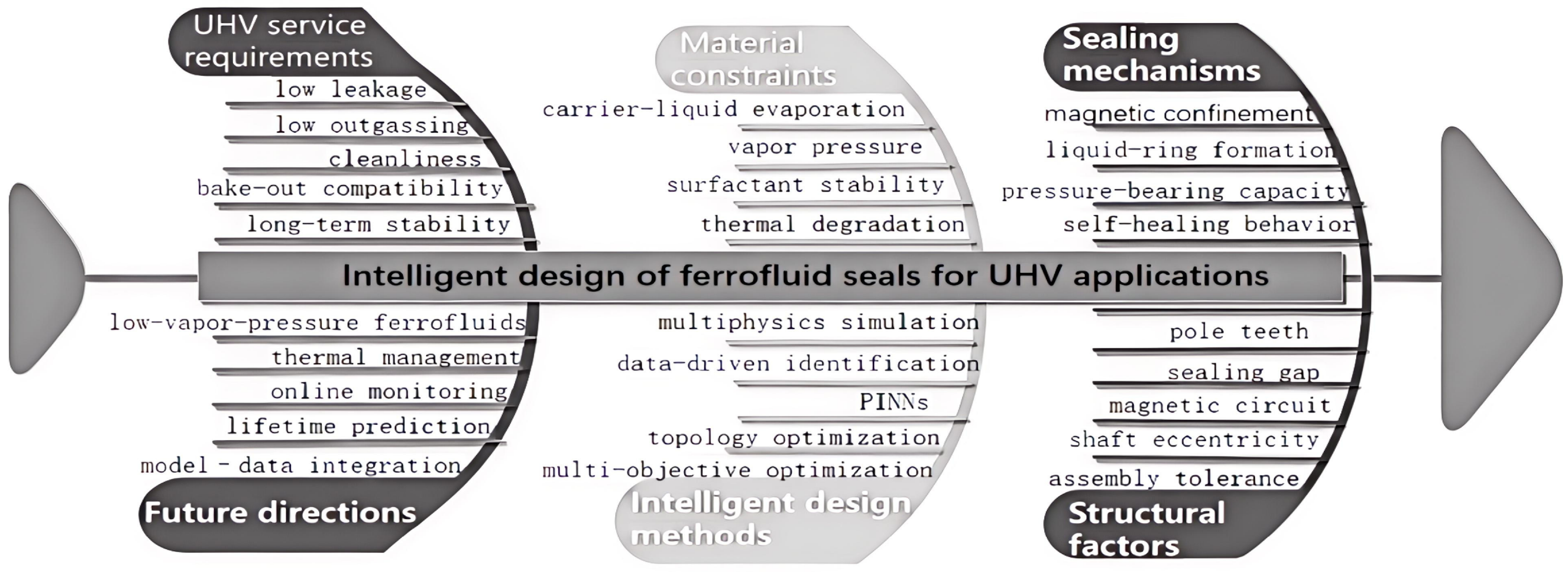
Recent studies have gradually shifted from empirical structural design to simulation- and data-assisted intelligent design, including multiphysics numerical simulation, parameter optimization, data-driven condition identification, physics-informed neural networks (PINNs), topology optimization, and multi-objective optimization [22,23,24,25,26,27,28]. Nevertheless, research on ferrofluid seals for UHV applications remains fragmented. Existing studies mainly focus on magnetic-field analysis, structural optimization, leakage behavior, or failure identification, while systematic reviews linking UHV service constraints with intelligent design methods are still limited. As shown in Figure 1, this review summarizes the field from five aspects: UHV service requirements, ferrofluid sealing mechanisms, key limiting factors, intelligent design methods, and future research directions. The aim is to clarify the key challenges and development routes for reliable ferrofluid seals in UHV applications.

2. Fundamentals, Industrial Applications, and UHV Characteristics of Ferrofluid Seals

2.1. Basic Principles of Ferrofluid Sealing

Ferrofluid is a stable colloidal suspension composed of nanoscale magnetic particles, a carrier liquid, and surfactants. It combines the flowability of a liquid with magnetic responsiveness, which provides the physical basis for ferrofluid sealing. Under an external magnetic field, the magnetic particles respond to the field gradient, while the carrier liquid allows the medium to remain deformable and mobile. This combination enables ferrofluid to act as a liquid sealing medium that can be spatially confined by magnetic forces [29].
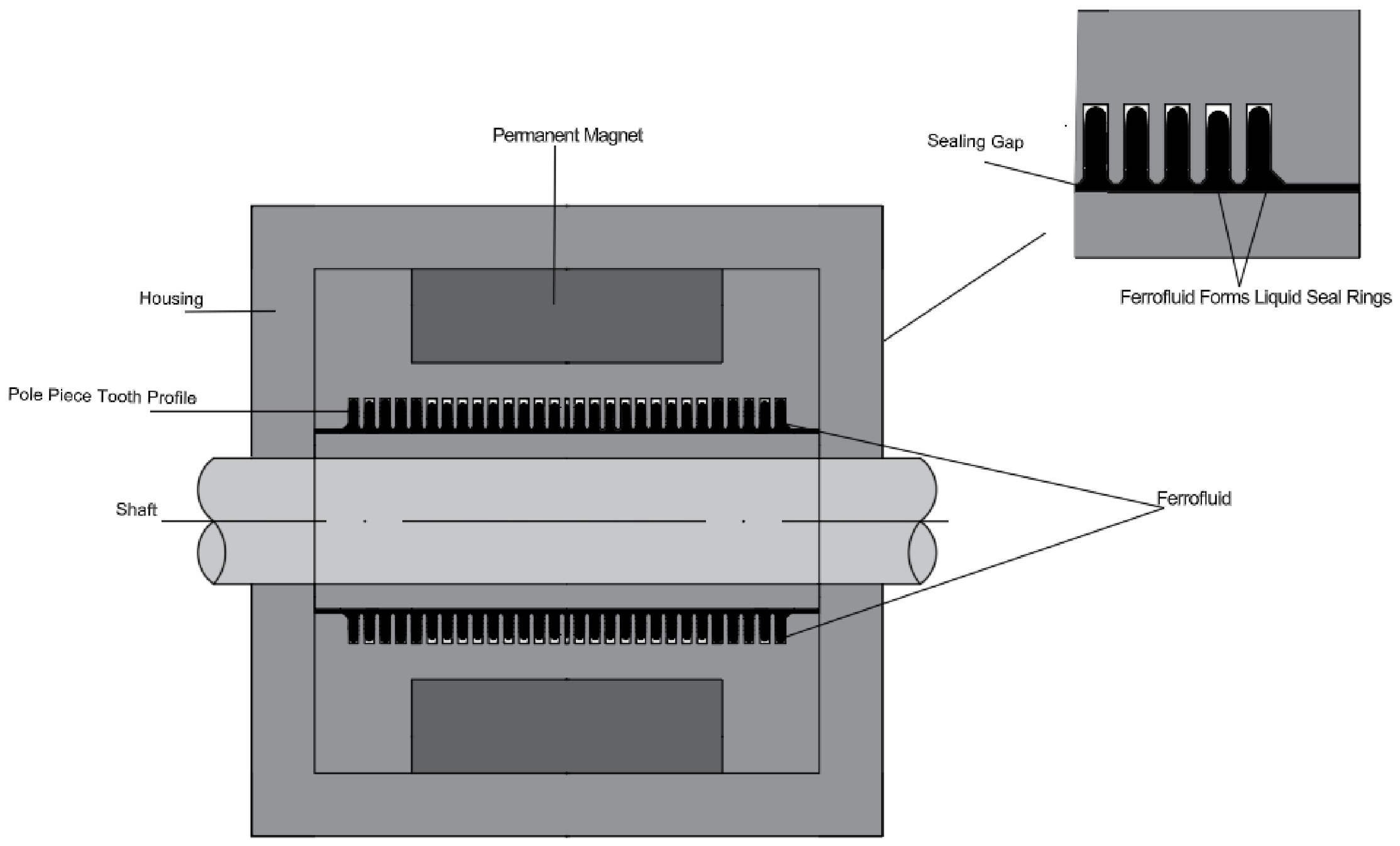
In a typical ferrofluid seal, a permanent magnet or an electromagnet provides the magnetic source, while the pole shoes, pole teeth, shaft, and sealing gap form the magnetic circuit. As shown in Figure 2, the magnetic field is concentrated near the pole teeth, and the ferrofluid is retained in the narrow sealing gap under the magnetic-field gradient. As a result, several liquid sealing rings are formed in series around the shaft or sealing interface. This mechanism enables the ferrofluid to form a magnetically retained liquid barrier in the sealing gap, which is the physical basis of ferrofluid sealing [30].
When a pressure difference is applied across the seal, the ferrofluid rings deform but remain confined by the magnetic field. The sealing state is governed by the balance among magnetic confinement, pressure difference, viscous resistance, interfacial effects, and structural boundary conditions. For static or low-speed operation, the ferrofluid Bernoulli equation is commonly used to describe the static or quasi-static equilibrium of ferrofluid seals:
p + 1 2 ρ v 2 + ρ g h μ 0 0 H M d H = C
where (p) is the local pressure of the ferrofluid, (ρ) is the ferrofluid density, (v) is the flow velocity, (g) is the gravitational acceleration, (h) is the height relative to the reference plane, ( μ 0 ) is the vacuum permeability, (M) is the magnetization intensity, (H) is the magnetic field intensity, and (C) is a constant [17,21].
For a static seal or a low-speed seal, the pressure-bearing capacity of the (i)-th pole tooth can be approximately expressed as follows:
P i = μ 0 M s ( H i , m a x H i , m i n )
where ( P i ) is the pressure-bearing capacity of the (i)-th pole tooth, ( M s ) is the saturation magnetization of the ferrofluid, ( H i , m a x ) is the maximum magnetic field intensity near the (i)-th pole tooth, and ( H i , m i n ) is the minimum magnetic field intensity near the same pole tooth [17,21].
For a multistage ferrofluid seal, the total pressure-bearing capacity can be approximately written as follows:
P i = 1 N p i
where ( P ) is the total pressure-bearing capacity of the multistage seal and (N) is the number of effective sealing stages. This expression is an idealized approximation and assumes that each sealing stage contributes effectively to the total pressure-bearing capacity. In practical designs, this approximation should be used with caution because the effective contribution of each stage depends on the magnetic circuit, gap size, and flux distribution [17,21].
This principle indicates that ferrofluid sealing is not simply the use of liquid to block a gap. Its core is the stable magnetic confinement of ferrofluid at effective sealing positions. The sealing capacity depends on the saturation magnetization and stability of the ferrofluid, the sealing gap, the pole-tooth geometry, the number of sealing stages, and the local magnetic-field gradient. If the magnetic-field gradient is weakened by gap variation, temperature rise, centrifugal effects, or medium loss, the liquid sealing rings may become unstable, leading to pressure transmission, local ruptures, and leakage.

2.2. Engineering Structures and Industrial Applications

The earliest mature engineering form of ferrofluid sealing was the vacuum rotary shaft seal. Bailey reported that magnetic liquid vacuum seals could be used in rotating vacuum shaft systems, indicating that multistage liquid-ring sealing had already shown practical feasibility in vacuum rotary feedthroughs at an early stage [31]. In the broader development of magnetic-fluid technology, sealing has also been recognized as one of the earliest and most successful commercial applications of ferrofluids [32].
A typical rotary ferrofluid seal consists of a rotating shaft, pole shoes, pole teeth, permanent magnets, ferrofluid, and a housing. The pole teeth divide the sealing gap into several stages, and each stage retains a ferrofluid ring under magnetic confinement. Therefore, the structural design of a ferrofluid seal is essentially a coupled design of the mechanical structure and the magnetic circuit.
Ferrofluid seals have been applied in several industrial and scientific systems. In semiconductor manufacturing, wafer-handling robots require reliable sealing when rotational motion is transmitted into a vacuum chamber, and magnetic-fluid rotary seals have been studied for such operating conditions [33]. In robot joints and modular vacuum transmission units, magnetic-fluid rotary seals have also been investigated to improve compactness, reduce wear, and maintain sealing reliability [34]. In precision machinery, magnetic-fluid-based seals have been used for high-speed and high-precision spindles because they can reduce friction torque while maintaining sealing capability [35]. In biomedical rotary devices, magnetic fluid seals have been applied to rotary blood pumps, showing their potential in liquid-contact rotating systems where conventional contact seals may introduce additional friction and wear [36].
For liquid-medium sealing, the main challenge is no longer only whether the seal can bear pressure, but whether the ferrofluid can remain stable when it is in direct contact with the sealed liquid. Liquid contact may cause washout, dilution, interface disturbance, or gradual loss of ferrofluid, thereby shortening the service life of the seal [37]. To address this problem, replenishment-type ferrofluid rotary seals have been proposed to compensate for ferrofluid degradation and loss during liquid-sealing operation [38]. For large-clearance or structurally complex conditions, studies have examined variable radial clearance and two-stage magnetic-fluid vacuum seals to improve sealing adaptability under non-ideal geometry [39]. Radial-charged magnet structures have also been investigated to enhance seal pressure and magnetic-field utilization under special magnetic-circuit configurations [40]. In large scientific facilities, ferrofluid rotating vacuum seals have been introduced in rotating target systems that require simultaneous rotation and vacuum maintenance [41].
Although not all of these applications operate under UHV conditions, they reveal the engineering advantages and practical limitations of ferrofluid sealing. These aspects are still relevant to the reliability design of ferrofluid seals for UHV applications, especially in relation to cleanliness, fluid retention, medium compatibility, thermal stability, and long-term operation.
Table 1 summarizes representative application fields of ferrofluid seals and their main engineering concerns.

2.3. Performance Characteristics and Practical Constraints of Ferrofluid Seals

The main advantages of ferrofluid seals arise from their non-contact liquid sealing mechanism. Since the sealing medium is retained by a magnetic field rather than by mechanical compression, direct solid–solid friction is reduced. This gives ferrofluid seals low wear, low friction torque, smooth operation, and relatively long service life. The liquid sealing rings may also show a certain recovery capability under magnetic confinement when the disturbance is small. These characteristics make ferrofluid seals attractive for clean vacuum equipment, precision rotary transmission, and systems in which particle contamination must be minimized.
However, ferrofluid seals also have inherent limitations. Their pressure-bearing capacity is strongly dependent on the magnetic-field gradient, sealing gap, ferrofluid magnetization, and stage arrangement. A small increase in the sealing gap or a decrease in magnetic-field strength can significantly reduce sealing performance. Numerical algorithms for magnetic-fluid seals and critical-pressure calculations have shown that geometric and magnetic parameters directly affect the pressure-bearing capability of ferrofluid seals [42,43].
Material stability is another major limitation. The ferrofluid itself may deteriorate because of carrier-liquid evaporation, oxidation, surfactant instability, particle agglomeration, or contamination. Under high-speed operation, temperature rise and centrifugal effects may cause fluid loss and uneven ring distribution. Numerical and experimental studies under high-speed conditions have shown that dynamic operation can substantially change sealing behavior compared with static or low-speed cases [44]. Thermal characteristics inside the sealing gap further indicate that the temperature field must be considered when evaluating seal stability [45]. In liquid-medium applications, medium compatibility and washout remain important problems, especially when the sealed liquid interacts directly with the ferrofluid [46].
Therefore, ferrofluid seals should not be regarded as universal replacements for conventional seals. Their advantages are most evident in clean, non-contact, rotary, and vacuum transmission conditions. Their weaknesses become more pronounced under high temperature, high speed, large gap variation, liquid-medium contact, long-term operation, and UHV processing procedures.
Table 2 summarizes the advantages and limitations of ferrofluid seals.

2.4. Key Constraints Under UHV Conditions

UHV conditions impose more stringent requirements on ferrofluid seals than ordinary vacuum environments. In conventional vacuum applications, the main concern is often whether the seal can withstand the required pressure difference. In UHV systems, however, sealing performance is also governed by gas load, material outgassing, surface cleanliness, thermal history, and long-term material stability. Vacuum materials used in accelerator and high-end scientific equipment must satisfy strict requirements related to material selection, cleanliness, heat treatment, outgassing, and leak-tightness [47,48].
The pressure at a given location in a vacuum system can be expressed as follows [47,49]:
P = Q S e f f
where (P) is the actual pressure at a given location in the vacuum system, (Q) is the total gas load, and ( S e f f ) is the effective pumping speed [1].
This relationship indicates that, even if there is no macroscopic leakage, an increase in gas load caused by material outgassing or carrier-liquid evaporation can still deteriorate the vacuum level. Analytical studies of accelerator vacuum systems also show that gas desorption, wall outgassing, and pumping conditions jointly determine the vacuum-state evolution in complex beamline structures [49].
The first constraint is carrier-liquid evaporation and material outgassing. The carrier liquid determines the flowability, viscosity, vapor pressure, and thermal stability of the ferrofluid. Under UHV conditions, slow evaporation may change the viscosity and magnetic response of the ferrofluid while increasing the background gas load. This issue is particularly important because medium-temperature bake-out and material treatment are often used to reduce outgassing rates in UHV systems [50]. For ferrofluid seals, low-vapor-pressure carrier liquids and vacuum-compatible magnetic fluids are therefore essential to reduce contamination and maintain sealing stability [51].
The second constraint is leakage-path sensitivity. Ferrofluid sealing relies on a stable liquid ring in a narrow gap, but UHV systems are also sensitive to microscopic leakage paths, surface defects, and contact-interface imperfections. Studies on metallic seals show that even non-magnetic conventional sealing structures can be affected by microscopic leakage channels formed by surface roughness and contact conditions [52]. This comparison indicates that UHV ferrofluid seals must be evaluated not only from the perspective of magnetic pressure capacity, but also from the perspective of leakage-path control and vacuum cleanliness.
The third constraint is magnetic-field distortion caused by geometric errors. Shaft eccentricity, radial runout, assembly error, thermal expansion, and deformation of thin-wall parts may change the local magnetic flux density. As a result, liquid rings may become unevenly distributed, and weak regions may develop into leakage paths.
The fourth constraint is thermal and high-speed coupling. A temperature rise can alter viscosity, accelerate carrier-liquid evaporation, reduce magnetic stability, and weaken liquid-ring retention. High-speed rotation may further induce centrifugal throwing and fluid loss. Therefore, UHV ferrofluid seal design must include thermal management rather than relying only on room-temperature magnetic-field analysis.
The fifth constraint is compatibility with UHV processing procedures. UHV systems often require leak detection, cleaning, baking, and long-term pumping before operation. Ferrofluid seals containing organic carrier liquids may have lower thermal tolerance than all-metal UHV components. Therefore, bake-out compatibility, low-vapor-pressure carrier liquids, low-outgassing materials, and differential pumping strategies are important for UHV-oriented ferrofluid seal design.
Overall, the key constraints on ferrofluid seals under UHV conditions can be summarized as medium stability, gas-load control, magnetic-field retention, thermal management, leakage-path control, and long-term reliability. These constraints explain why the design of UHV ferrofluid seals cannot remain limited to traditional pressure-bearing formulas. A more suitable design framework should integrate ferrofluid material selection, magnetic circuit configuration, structural tolerance, thermal behavior, industrial operating conditions, and reliability prediction.

3. Research Progress in Intelligent Design and Performance Prediction Methods for Ferrofluid Seals in UHV Applications

3.1. Multiphysics Simulation and Modeling

The design of ferrofluid seals was initially dominated by theoretical pressure-bearing formulas and static magnetic-field calculations. This approach is useful for estimating the basic pressure capacity of a sealing structure, but it cannot fully describe seal behavior under realistic rotary operation. In practical rotary seals, magnetic-field distribution, ferrofluid retention, viscous heating, shaft motion, gap variation, and structural deformation are coupled with each other. For UHV-oriented ferrofluid seals, these interactions become more critical because local magnetic-field weakening, temperature rise, or microscopic gap variation may directly affect liquid-ring stability and leakage-path formation. Therefore, ferrofluid seal modeling is gradually moving from single-field magnetic analysis toward coupled multiphysics simulation.
Finite element analysis remains the main numerical tool for this transition. In magnetic-fluid seal studies, finite element models are commonly used to calculate the magnetic flux density, magnetic-field gradient, and local magnetic force in the sealing gap. These quantities are then used to estimate the pressure-bearing capacity of each sealing stage. However, the value of finite element modeling is not limited to static pressure calculations. It also provides a basis for evaluating how structural parameters, shaft motion, and material properties influence the local field distribution. For example, numerical and experimental studies on magnetic fluid seals with large sealing gaps and multiple magnetic sources have shown that the relationship between theoretical pressure capacity and measured pressure capacity may become less consistent when the sealing gap increases beyond a certain range [53]. This result indicates that idealized magnetic-field models may lose accuracy under large-clearance or non-ideal geometric conditions.
For rotary ferrofluid seals, the rotating shaft should be treated as an active part of the magnetic circuit rather than a simple geometric boundary. The ferrofluid rings are retained between the pole teeth and the shaft surface; therefore, shaft eccentricity, radial runout, surface deformation, and centrifugal effects can disturb the local sealing gap and cause nonuniform magnetic confinement. Recent work on high-speed magnetic fluid sealers with shaft eccentricity further shows that shaft misalignment can change the magnetic field, velocity field, and pressure distribution in the working gap, thereby reducing the retained pressure difference in the seal [54]. This issue is especially important for UHV applications because even local weakening of the ferrofluid ring may increase the risk of pressure transfer, fluid thinning, or microscopic leakage. Therefore, magnetic-field simulation for UHV-oriented rotary seals should gradually move from ideal axisymmetric models to rotating-shaft-based models that include eccentricity, gap variation, centrifugal force, and thermal deformation.
In numerical modeling, multiphysics simulation of ferrofluid seals is usually constructed by coupling magnetostatic analysis, flow-field calculation, heat-transfer analysis, and, when necessary, structural deformation analysis. The specific governing equations and coupling terms depend on the modeling assumptions, such as whether the ferrofluid is treated as an incompressible Newtonian liquid, whether magnetization is assumed to be linear or nonlinear, whether thermal effects are solved in a steady or transient form, and whether shaft deformation and gap variation are included. Therefore, this review does not list a unified set of governing equations for all ferrofluid seal models. Instead, it focuses on the modeling strategies, coupled physical fields, and remaining limitations that are most relevant to UHV-oriented ferrofluid seal design.
Thermal effects are a necessary part of rotary ferrofluid seal modeling. A temperature rise may change the viscosity, magnetization, carrier-liquid stability, and evaporation tendency of the ferrofluid. In miniature rotary pump applications, thermal analysis has shown that the temperature of the magnetic fluid seal is affected by heat transfer conditions around the seal housing and by heat input from the motor, while the influence of viscous friction in the magnetic fluid may depend on the specific seal structure and operating conditions [55]. For large rotating equipment, thermal expansion becomes more important because temperature-induced radial displacement of the shaft and pole shoes can change the sealing gap. Recent coupled thermal–hydraulic–mechanical simulations of magnetic fluid seals for large centrifuges showed that rotational speed, thermal expansion, shaft material, and pole-shoe material can jointly affect the sealing gap and pressure response [56]. From the perspective of structural reliability, thermal and mechanical loads may further affect seal housing strength and fatigue life. Reliability-oriented thermal–mechanical modeling has therefore been introduced to evaluate and optimize magnetic fluid dynamic seal structures under coupled load conditions [57]. These studies indicate that thermal analysis should not be treated as an auxiliary calculation after magnetic-field simulation, but as part of the coupled performance evaluation of rotary ferrofluid seals.
From the perspective of UHV service, multiphysics simulation should also consider vacuum-related constraints. Static magnetic-field models can estimate pressure capacity, but they cannot directly predict the gas load, carrier-liquid evaporation, bake-out influence, or long-term degradation of ferrofluid properties. Similarly, purely thermal models cannot fully describe leakage-path formation if the magnetic field, gap evolution, and ferrofluid retention state are not included. Therefore, UHV-oriented simulation should gradually develop toward a coupled framework involving magnetic field, flow behavior, thermal response, structural deformation, gas-load evolution, and seal-state degradation. To clarify the modeling scope and remaining limitations of the existing approaches, Table 3 summarizes representative multiphysics simulation methods and their relevance to ferrofluid seal design.
Overall, multiphysics modeling provides the most mature technical basis for intelligent design of ferrofluid seals. Its role should not be limited to calculating theoretical pressure capacity. For UHV ferrofluid seals, future simulations should focus on rotating-shaft-based magnetic-field modeling, eccentricity-induced gap variation, thermal expansion, material-property changes, and vacuum-related gas-load behavior. A more scientific modeling framework should couple magnetic confinement, ferrofluid motion, heat transfer, structural deformation, and long-term degradation so that seal design can move from static pressure estimation to reliability-oriented prediction.

3.2. Data-Driven Condition Identification

Compared with structural design and multiphysics simulation, data-driven condition identification for ferrofluid seals is still at an early stage. However, it is an important prerequisite for intelligent design, online monitoring, and predictive maintenance. During operation, the sealing gap of a ferrofluid seal is usually very small, and the distribution, migration, thinning, and rupture of the ferrofluid rings are difficult to observe directly after assembly. For UHV-oriented ferrofluid seals, direct visualization becomes even more difficult because the sealing process occurs inside a closed vacuum system. Therefore, condition identification based on external sensing signals provides a possible route for evaluating the internal sealing state without disassembling the device.
Acoustic emission (AE) monitoring provides a useful sensing route for enclosed rotary systems because it is sensitive to transient elastic waves caused by friction, impact, leakage, crack initiation, and local failure events [58]. For ferrofluid seals, this method is relevant because liquid-ring rupture, pressure transfer, and local interface disturbance may produce indirect dynamic signals even when the sealing gap cannot be directly observed. From a broader intelligent fault-diagnosis perspective, machine learning and deep learning methods have been widely used to establish nonlinear mappings between monitoring signals and equipment health states [59,60]. Therefore, AE features, vibration signals, temperature signals, pressure signals, and vacuum-level signals may be used as external indicators for ferrofluid seal condition identification. However, direct application to UHV ferrofluid seals still requires dedicated datasets, controlled degradation tests, and validation under vacuum-related operating conditions.
For ferrofluid seals, data-driven condition identification has two main advantages. First, it improves the observability of an otherwise enclosed sealing system. Since the ferrofluid ring cannot be directly observed during operation, sensing signals such as AE, temperature, vibration, pressure, and vacuum level can provide indirect information about liquid–film rupture, pressure transfer, and seal degradation. Second, data-driven models can capture complex nonlinear relationships between external signals and internal sealing states, especially when the failure process is difficult to express using an explicit analytical model. These advantages make data-driven methods useful complements to multiphysics simulation, particularly for monitoring and diagnosis under operating conditions.
Nevertheless, current research remains limited. Most existing diagnostic models are trained in laboratory or controlled operating conditions. The available datasets are usually small, and the transferability of trained models across different seal structures, ferrofluid materials, rotational speeds, pressure ranges, and vacuum levels has not been fully verified. This issue is closely related to a domain shift in intelligent fault diagnosis, where models trained under one operating condition may show reduced accuracy when applied to different structures, speeds, loads, or environments. Deep transfer learning has therefore become an important direction for improving the generalization ability of diagnostic models across working conditions [61]. In addition, many diagnostic models output discrete condition categories rather than continuous health indicators. For UHV ferrofluid seals, continuous indicators such as remaining pressure-bearing margin, leakage probability, degradation rate, and remaining useful life are more useful for reliability-oriented maintenance. Remaining useful life prediction has been widely studied in prognostics and health management, but its application to ferrofluid seals remains insufficient [62]. The main data-driven condition identification methods and possible extensions for ferrofluid seals are summarized in Table 4.
The data–mechanism fusion row represents a possible extension summarized in this review, rather than a mature method already established for UHV ferrofluid seals.
Overall, data-driven condition identification has the potential to improve the monitoring capability of ferrofluid seals by converting indirect sensing signals into internal state information. Compared with multiphysics simulation, it is closer to online diagnosis and maintenance decision-making. However, the current stage of development is still mainly condition recognition, rather than true performance prediction. For UHV ferrofluid seals, future research should focus on establishing reliable datasets under vacuum and UHV-related conditions, developing transferable models across different seal structures and operating conditions, and integrating sensing data with physical models to predict continuous degradation indicators rather than only discrete leakage states.

3.3. From Mechanism-Constrained Surrogate Models to Low-Sample Performance Prediction Physics-Informed Neural Networks

Physics-informed neural networks (PINNs) provide a possible route for low-sample modeling and mechanism-constrained prediction. Unlike purely data-driven neural networks, PINNs incorporate governing equations, boundary conditions, initial conditions, and observational data into the loss function, thereby constraining model training with physical residuals when labeled data are limited [63,64]. This characteristic is particularly relevant to UHV ferrofluid seals, because experiments under UHV conditions are difficult, expensive, and often limited by closed structures, long pumping processes, and strict cleanliness requirements.
From the perspective of ferrofluid seal modeling, PINNs may be useful in three aspects. First, they can be used as surrogate models for magnetic-field prediction. In conventional design, the magnetic flux density and magnetic-field gradient in the sealing gap are usually obtained through finite element simulation. However, repeated finite element scans are computationally expensive when the pole-tooth geometry, sealing gap, magnet size, and material parameters are varied. A mechanism-constrained surrogate model could map design parameters to magnetic-field distribution and pressure-bearing indicators while reducing the number of repeated simulations. Second, PINNs may help establish coupled magnetic–flow–thermal models. Since ferrofluid sealing involves magnetic confinement, pressure transmission, viscous flow, and heat generation, a model that embeds flow and thermal equations into the training process could improve prediction under sparse experimental data. Third, PINNs may support inverse identification of uncertain parameters, such as effective viscosity, local heat source, boundary heat-transfer coefficient, and degradation-related material parameters.
However, direct applications of PINNs to ferrofluid seals are still scarce. Most available evidence comes from general physics-informed machine learning, fluid mechanics, magnetic-field modeling, and numerical methods for interface or conservation-law problems. Therefore, PINNs should not be described as a mature method for ferrofluid seal design at the present stage. Instead, they should be regarded as a mechanism-constrained modeling strategy that may be introduced into ferrofluid seal research by drawing on progress in related fields.
Karniadakis et al. summarized the concept of physics-informed machine learning and emphasized its value in combining data with physical laws for scientific computing [65]. Cuomo et al. further reviewed the development of PINNs and discussed their advantages and open challenges in solving differential equations and inverse problems [66]. In fluid mechanics, Cai et al. showed that PINNs can be used for flow-field reconstruction, inverse parameter identification, and data assimilation in systems governed by partial differential equations [65]. These studies provide methodological support for introducing PINNs into ferrofluid seal modeling, but they do not directly solve the specific problems of magnetic-fluid sealing.
A more closely related direction can be found in magnetic-field modeling. Hou et al. applied a physics-informed neural network to the magnetic-field simulation of coaxial magnetic gears. By incorporating governing equations and interface continuity conditions into the loss function, the model improved magnetic-field prediction and showed potential as a surrogate modeling tool for magnetic devices [66]. The key methodological point is not only the use of PINNs themselves, but also the treatment of material interfaces and discontinuous field properties. For ferrofluid seals, this issue is important because the seal contains multiple interfaces among permanent magnets, pole shoes, air gaps, shafts, and ferrofluid. Therefore, magnetic-field PINN studies should be used as methodological references rather than as direct evidence that PINNs have already matured in ferrofluid seal design.
The application of PINNs to UHV ferrofluid seals should therefore be understood as a future-oriented research direction rather than a mature design method. At the current stage, PINNs are more suitable as mechanism-constrained surrogate models, inverse-identification tools, or auxiliary models coupled with a finite element simulation. Their reliability depends on the correctness of the embedded governing equations, the treatment of discontinuous material interfaces, the quality of sparse experimental data, and the stability of training. Existing studies have shown that PINNs may suffer from training instability, imbalance among different loss terms, spectral bias, and reduced accuracy for multiscale or stiff problems [67]. These issues are especially important for ferrofluid seals, where magnetic-field gradients, narrow sealing gaps, and thermal–fluid coupling can produce strong spatial nonuniformity.
In addition to general PINN frameworks, several methodological developments are also relevant to ferrofluid seal modeling. DeepXDE provides a general framework for solving forward and inverse differential-equation problems, which is useful for building prototype PINN models [68]. Conservative PINNs introduce domain decomposition and flux-continuity constraints across subdomains, which may be useful for sealing problems involving narrow gaps, material interfaces, and localized field gradients [69]. For fluid-related problems, Navier–Stokes flow networks provide a direct example of embedding incompressible-flow equations into neural-network training [70]. These studies suggest that PINNs are not limited to solving isolated equations, but can be extended to coupled or domain-decomposed physical systems.
For UHV-oriented ferrofluid seals, a realistic development path is to combine PINNs with existing multiphysics simulation and sensing data. In the design stage, finite element simulation can provide baseline magnetic-field and temperature-field data for training a surrogate model. In the experimental stage, limited measurements of temperature, pressure, acoustic emission, and vacuum level can be introduced as additional constraints. In the prediction stage, the trained model can be used to estimate the pressure-bearing margin, thermal risk, or early leakage tendency under parameter variations. In this way, PINNs may help bridge the gap between mechanism-based modeling and data-driven diagnosis. Based on the above discussion, Table 5 summarizes the potential roles, physical constraints, methodological basis, relevance, and limitations of PINNs in ferrofluid seal modeling.
Overall, PINNs provide a promising but still immature route for ferrofluid seal performance prediction. Their main value lies in reducing dependence on large finite element datasets, incorporating physical constraints into low-sample learning, and enabling inverse identification of difficult-to-measure parameters. However, direct PINN applications in ferrofluid seal research remain limited. For UHV applications, future studies should avoid treating PINNs as a purely fashionable algorithm. Instead, they should focus on physically meaningful problem definitions, validated governing equations, reliable sparse measurements, interface treatment, and comparison with finite element and experimental results.

3.4. Topology Optimization: From Parametric Optimization to Magnetic Circuit Material Distribution Optimization

Topology optimization provides a design strategy that is different from conventional parameter optimization. In parameter optimization, the basic structure is usually fixed in advance, and only geometric dimensions such as the pole-tooth width, pole-tooth height, sealing gap, magnet thickness, or pole-shoe profile are adjusted. In topology optimization, by contrast, the material distribution within a prescribed design domain is optimized directly under specified objective functions and constraints. This approach can determine the spatial distribution of permanent magnets, ferromagnetic materials, nonmagnetic materials, and air regions with greater design freedom. For ferrofluid seals, this idea is particularly relevant because the pressure-bearing capacity depends strongly on the magnetic-field gradient and flux distribution in the sealing gap.
In related magnetic devices, topology optimization has already shown clear potential. General topology optimization theory and comparative reviews have established the methodological basis for material distribution design under structural, physical, and manufacturing constraints [71,72,73]. Bjørk et al. applied topology optimization to permanent magnet systems composed of permanent magnets, high-permeability iron, and air regions. Their study showed that topology optimization could improve magnetic efficiency and generate magnetic-field distributions that are difficult to obtain using conventional structural design [74]. Huber et al. further combined topology optimization with additive manufacturing of polymer-bonded permanent magnets, showing that optimized magnetic structures could be fabricated to generate predefined external magnetic fields [75]. In stellarator design, Zhu et al. developed a topology optimization approach for permanent magnet systems and used it to determine the spatial distribution of magnets under engineering constraints [76]. In electric motor design, multi-material topology optimization has also been introduced to distribute ferromagnetic materials, air regions, and permanent magnets while considering magnetization direction [77]. These studies indicate that topology optimization is especially suitable for magnetic systems in which field distribution, material utilization, and spatial constraints are strongly coupled. Recent reviews on topology optimization for magnetic devices further show that this method has become an important route for improving magnetic-field performance, material utilization, and structural innovation in electromagnetic systems [78].
For ferrofluid seals, however, topology optimization in the strict sense remains limited. Existing studies still mainly rely on candidate structure comparisons, dimensional optimization, and finite element verification. For example, large-clearance ferrofluid seals have been improved by introducing divergent magnetic circuits and dual magnetic sources, aiming to increase the magnetic flux density in the sealing gap and improve pressure-bearing capacity under non-ideal clearance conditions [79]. This type of work is important for structural innovation, but it is not yet topology optimization in the strict sense because the design domain and material distribution are not automatically optimized.
In addition to application-oriented studies, the methodological development of electromagnetic topology optimization should also be considered. Recent surveys on topology optimization for electromagnetics have shown that density-based methods, level-set methods, phase-field methods, evolutionary methods, and hybrid strategies have all been used in electromagnetic device design [80]. Among these approaches, level-set and phase-field methods are useful for generating clear material boundaries, while density-based methods are more convenient for continuous material interpolation and sensitivity analysis [81,82]. Hybrid strategies that combine global search with local topology refinement have also been proposed to improve the diversity and quality of optimized magnetic structures [83]. For practical magnetic-circuit design, nonlinear magnetic materials and manufacturability are also important. Material-density-based topology optimization with magnetic nonlinearity has been proposed to treat nonlinear iron-core behavior in realistic electromagnetic devices [84]. Multi-material topology optimization considering permanent-magnet nonlinearity further indicates that the interpolation of magnetic properties can significantly affect optimized geometry and performance [85]. In addition, the integration of topology optimization with additive manufacturing has opened the possibility of fabricating complex magnetic components that are difficult to obtain with conventional machining [86]. Level-set-based optimization of permanent magnets for generators also shows that topology optimization can be used to improve magnetic-field performance under engineering constraints [87].
The gap between structural innovation and topology optimization is important. In many ferrofluid seal studies, a new magnetic circuit or pole-tooth structure is proposed first, and then its performance is evaluated by a finite element simulation or experiment. This approach can improve specific designs, but it still depends heavily on designer experience. Topology optimization would allow the design process to start from a broader design domain, where the algorithm determines whether a local region should be occupied by permanent magnet material, soft magnetic material, nonmagnetic structural material, or air. In this way, it may discover magnetic-circuit layouts that are difficult to obtain through manual design.
From the perspective of objective functions, ferrofluid seals are suitable for topology optimization. The objective may be defined as maximizing the magnetic flux density difference in the sealing gap, increasing the magnetic-field gradient near the pole teeth, reducing magnetic leakage, improving the effective utilization of permanent magnet material, or enhancing the robustness of magnetic-field distribution under gap variation and shaft eccentricity. For UHV applications, additional constraints should also be considered, including compactness, manufacturability, thermal deformation, bake-out compatibility, low-outgassing material selection, and structural tolerance. Therefore, a UHV-oriented topology optimization framework should not only maximize pressure-bearing capacity, but also maintain magnetic-field stability under long-term operation, assembly deviation, and thermal loading.
A possible workflow for introducing topology optimization into ferrofluid seal design can be summarized as follows. First, the design domain is defined around the pole shoe, pole-tooth root, magnet region, magnetic-conducting region, and surrounding installation space. The sealing gap and shaft space should be treated as non-design domains or evaluation regions, because they must preserve the functional space required for ferrofluid retention and shaft rotation. Second, the candidate materials are specified, such as permanent magnet, soft magnetic material, nonmagnetic structural material, and air. Third, the objective function is constructed using magnetic-field indicators in the sealing gap, such as magnetic flux density difference, field-gradient strength, and leakage-flux penalty. Fourth, engineering constraints, including minimum feature size, manufacturability, thermal deformation, and available installation space, are introduced. Finally, the optimized material distribution is reconstructed into a manufacturable magnetic-circuit structure and verified using multiphysics simulations and experiments. Based on the above discussion, Table 6 summarizes topology optimization and related structural optimization methods for magnetic devices and ferrofluid seals.
Overall, topology optimization offers a promising but still underdeveloped route for ferrofluid seal design. Compared with traditional parameter optimization, it provides greater freedom for magnetic-circuit design and may improve magnetic-field utilization under compact or constrained geometries. However, current ferrofluid seal research has not yet established a mature topology optimization framework. Most studies remain at the levels of structural innovation, dimensional adjustment, and finite element comparison. For UHV applications, future work should focus on defining physically meaningful objective functions, incorporating manufacturability and material compatibility constraints, and combining topology optimization with multiphysics simulation and experimental validation.

3.5. Multi-Objective Optimization: From Single Pressure-Bearing Enhancement to Collaborative Performance Design

Multi-objective optimization is one of the most practical routes for intelligent design of ferrofluid seals. Traditional ferrofluid seal design often focuses on improving the pressure-bearing capacity by adjusting one or several structural parameters, such as the sealing gap, pole-tooth width, pole-tooth height, pole-tooth angle, magnet thickness, and ferrofluid volume. However, UHV-oriented ferrofluid seals cannot be evaluated only by maximum pressure resistance. They must also consider thermal stability, friction torque, structural compactness, material compatibility, manufacturing tolerance, outgassing risk, and long-term reliability. Therefore, the design problem gradually shifts from single-objective pressure enhancement to collaborative performance design.
Existing optimization studies on magnetic-fluid sealing systems have mainly focused on geometric parameter selection and pressure-bearing improvement. Parmar et al. optimized several design parameters affecting the performance of a magnetic fluid rotary seal by combining finite element magnetic-field calculation with regression-based analysis, showing that numerical simulation data can support parameter optimization and design decision-making [88]. This type of work indicates that ferrofluid seal design has moved beyond purely empirical parameter selection. However, it remains closer to multi-parameter single-objective optimization than strict multi-objective optimization, because the final objective is often still the improvement of pressure-bearing capacity.
For UHV applications, single-objective pressure enhancement is insufficient. A seal structure with high pressure-bearing capacity may still be unsuitable if it causes excessive temperature rise, high gas load, poor bake-out compatibility, or strong sensitivity to assembly error. In related magnetic-fluid sealing technologies, multi-objective optimization has begun to show clearer engineering value. Shen et al. proposed a multi-objective optimizer for magnetorheological fluid sealing structures, where maximum sealing pressure and minimum rotational friction torque were used as two objective functions [89]. Although this work is not a ferrofluid seal study in the strict sense, it provides a useful reference for magnetic-fluid-related sealing systems, because pressure capacity and rotational resistance are also conflicting objectives in many ferrofluid sealing applications. In general multi-objective optimization, Pareto-based algorithms have been widely used to obtain trade-off solution sets when objectives conflict with each other [90,91,92,93,94,95]. These characteristics are consistent with ferrofluid seal design, where finite element simulation, experiments, and reliability assessments are often costly.
For UHV ferrofluid seals, the objective functions should be expanded according to the service requirements. The first objective is still pressure-bearing capacity, which is usually related to the magnetic flux density difference and magnetic-field gradient in the sealing gap. The second objective is thermal safety, including temperature rise, heat dissipation, and thermal influence on viscosity and carrier-liquid evaporation. The third objective is low friction and low disturbance during rotation, especially for high-precision rotary feedthroughs and clean motion systems. The fourth objective is vacuum compatibility, including low vapor pressure, low outgassing, and reduced contamination risk. The fifth objective is robustness, including tolerance insensitivity, resistance to shaft eccentricity, and stability after thermal deformation. The sixth objective is service reliability, which involves lifetime retention, maintenance convenience, and degradation prediction.
The optimization objectives of ferrofluid seals should not be restricted to improving the instantaneous pressure-bearing capacity. A high initial pressure-bearing value does not necessarily indicate reliable long-term operation, especially in UHV equipment where maintenance is difficult and contamination risk must be strictly controlled. Under long-term rotary operation, the ferrofluid may suffer from carrier-liquid evaporation, thermal degradation, particle aggregation, centrifugal loss, or local depletion. Therefore, future optimization should gradually include service-life retention, a ferrofluid replenishment strategy, and maintenance convenience. Replenishment-oriented design is particularly meaningful for dynamic seals because it can compensate for fluid degradation and loss, maintain the effective liquid-ring volume, and reduce the frequency of disassembly or replacement. Studies on centrifugal magnetic fluid seals for rotating shafts also indicate that seal design should consider not only the sealing capacity, but also lifetime, friction torque, and performance under variable rotational speeds [96].
The design variables should also be extended from geometric dimensions to material and operating parameters. In addition to pole-tooth width, pole-tooth height, sealing gap, and magnet dimensions, future optimization should include ferrofluid volume, saturation magnetization, carrier-liquid viscosity, pole-shoe material, magnet grade, cooling structure, and operating speed. For UHV applications, constraints such as available installation space, manufacturability, minimum feature size, bake-out temperature, material outgassing rate, and allowable temperature rise should also be included. This means that the optimization framework should be built not only for magnetic-field enhancement, but also for the integrated design of structure, material, thermal behavior, and reliability.
Surrogate-assisted optimization may become useful when repeated finite element simulations are computationally expensive. Since multi-objective optimization usually requires many evaluations of objective functions, direct coupling with finite element simulation may lead to a high computational cost. Surrogate models, such as response surface models, Kriging models, Gaussian-process models, neural networks, or other regression-based approximations, can be introduced to approximate the relationship between design variables and performance indicators. In general engineering optimization, surrogate-based and surrogate-assisted evolutionary computation have been widely discussed as effective ways to reduce the cost of expensive objective-function evaluations [97,98,99,100,101]. For UHV ferrofluid seals, this idea is relevant because pressure-bearing capacity, temperature rise, leakage risk, and reliability indicators may all require repeated multiphysics simulations or difficult experiments. However, surrogate models should be used with caution because their prediction accuracy depends strongly on sample coverage, model validation, and extrapolation ability. Based on the above discussion, Table 7 summarizes representative optimization methods for ferrofluid seal design and related sealing systems.
Overall, multi-objective optimization provides a practical framework for moving ferrofluid seal design from isolated parameter improvement to collaborative performance design. Compared with topology optimization and PINNs, it is closer to current engineering practice because it can be directly combined with finite element simulation, experimental data, and design constraints. However, the field has not yet established a mature UHV-oriented multi-objective optimization framework. Most studies still focus on the pressure-bearing capacity and structural parameters, while the thermal behavior, outgassing, material degradation, tolerance robustness, and service life are not fully integrated. Future work should therefore develop optimization models that combine magnetic-field performance, thermal safety, vacuum compatibility, and reliability prediction, and should use Pareto analysis to clarify the trade-off relationships among these objectives.
Overall, the intelligent design and performance prediction methods reviewed in this section show different levels of maturity. Multiphysics simulation is currently the most mature approach and provides the main basis for pressure-bearing, thermal, and structural analysis. Data-driven condition identification has improved the observability of enclosed ferrofluid seals, but it remains limited by small datasets and poor transferability. PINNs and topology optimization are promising for low-sample modeling and magnetic-circuit innovation, but their direct use in ferrofluid seals is still exploratory. Multi-objective optimization is closest to engineering implementation because it can combine the pressure capacity, thermal safety, vacuum compatibility, and reliability requirements within a unified decision framework.

4. Conclusions and Future Directions

This review focuses on the intelligent design and performance prediction of ferrofluid seals for ultra-high vacuum (UHV) applications. Its main objective is to clarify how UHV service constraints, ferrofluid sealing mechanisms, failure factors, and intelligent design methods can be connected within a reliability-oriented framework. Compared with general reviews on ferrofluid sealing structures or magnetic-fluid applications, this review emphasizes the specific challenges imposed by UHV environments, including low outgassing, low vapor pressure, thermal stability, liquid-ring retention, leakage-path control, and long-term reliability. Instead of simply classifying ferrofluid seals by structure or discussing intelligent algorithms separately, the literature is organized according to the chain of “UHV service requirements–failure constraints–intelligent design methods–future reliability objectives.”
The analysis shows that UHV ferrofluid seals cannot be evaluated only by their static or instantaneous pressure-bearing capacity. Although pressure resistance remains a basic performance indicator, long-term reliability is also affected by carrier-liquid evaporation, material outgassing, thermal degradation, shaft eccentricity, magnetic-field distortion, liquid-ring instability, and ferrofluid loss. Therefore, the design objective should shift from single pressure enhancement to integrated reliability design.
Among the reviewed methods, multiphysics simulation is currently the most mature approach. It links magnetic-field distribution, pressure-bearing capacity, thermal behavior, structural deformation, and liquid-film failure. For rotary ferrofluid seals, future simulations should pay more attention to rotating-shaft-based magnetic-field modeling, because shaft eccentricity, radial runout, rotational speed, and thermal deformation can change the magnetic-field distribution in the sealing gap. Data-driven condition identification provides a route for online monitoring, but it remains limited by small datasets, laboratory test conditions, and insufficient prediction of continuous health indicators.
PINNs, topology optimization, and multi-objective optimization represent three emerging directions for intelligent design. PINNs may support low-sample prediction and inverse identification, but direct applications to ferrofluid seals are still scarce. Topology optimization may enable non-intuitive magnetic-circuit design, but current ferrofluid seal studies remain mainly at the stage of structural comparison and finite element verification. Multi-objective optimization is closer to engineering implementation because it can integrate the pressure capacity, thermal safety, vacuum compatibility, tolerance robustness, and reliability into one design framework.
Future research should focus on five aspects. First, low-vapor-pressure and low-outgassing ferrofluids should be developed together with UHV-compatible structural materials, because heat treatment, coating, bake-out history, and material surface state can directly affect the gas load and attainable vacuum level [102]. Second, thermal management should be strengthened by coupling magnetic fields, flow behavior, temperature rise, structural deformation, evaporation, outgassing, and leakage-path evolution. Third, long-term reliability and durability should be evaluated under realistic operating conditions, including shaft eccentricity, clearance variation, thermal cycling, ferrofluid loss, and service-life retention. Fourth, online monitoring and fault diagnosis should be developed by integrating acoustic emission, temperature, vibration, pressure, and vacuum-level sensing with data–mechanism fusion models and condition-based maintenance strategies [96,103,104]. Fifth, intelligent optimization and reliability-oriented design methodologies should move beyond instantaneous pressure capacity and include thermal safety, low gas load, ferrofluid replenishment, maintenance convenience, shaft-tolerance robustness, and long-term reliability.
In conclusion, ferrofluid seals remain attractive for UHV rotary transmission because of their non-contact operation, low wear, and clean sealing potential. However, their future development depends on whether intelligent design can move beyond static pressure-bearing evaluation and address long-term reliability under realistic UHV service conditions. A reliable UHV ferrofluid seal should be designed not only to resist pressure at the initial state, but also to retain ferrofluid, suppress gas load, tolerate shaft and thermal deviations, support monitoring and prediction, and remain maintainable throughout its service life.

Author Contributions

Conceptualization, Y.Z. and Z.L.; methodology, Y.Z., Y.S. and S.L.; investigation, Y.Z., Y.S., W.L. and S.W.; formal analysis, Y.Z., Y.S. and M.S.; resources, S.L., M.S. and Z.L.; writing—original draft preparation, Y.Z.; writing—review and editing, Y.S., S.L., W.L., S.W., M.S. and Z.L.; supervision, Z.L.; project administration, Z.L.; funding acquisition, Z.L. All authors have read and agreed to the published version of the manuscript.

Funding

This research was funded by the Qinghai Provincial Department of Science and Technology, grant number 2025-ZJ-958M.

Data Availability Statement

No new data were created or analyzed in this study.

Conflicts of Interest

The authors declare no conflicts of interest.

References

  1. Umrath, W. (Ed.) Fundamentals of Vacuum Technology; Leybold GmbH: Cologne, Germany, 2016. [Google Scholar]
  2. Chiggiato, P. Outgassing properties of vacuum materials for particle accelerators. arXiv 2020, arXiv:2006.07124. [Google Scholar]
  3. Okabe, T.; Kondo, Y.; Yoshimoto, S.; Sasaki, S. Outgassing performance of an ionic liquid-based magnetic fluid. Vacuum 2019, 164, 34–40. [Google Scholar] [CrossRef]
  4. Rosensweig, R.E. Ferrohydrodynamics; Cambridge University Press: Cambridge, UK, 1985. [Google Scholar]
  5. Shliomis, M.I. Magnetic fluids. Sov. Phys. Usp. 1974, 17, 153–169. [Google Scholar] [CrossRef]
  6. Li, D.; Li, Y.; Li, Z.; Wang, Y. Theory analyses and applications of magnetic fluids in sealing. Friction 2023, 11, 1771–1793. [Google Scholar] [CrossRef]
  7. Zeng, Q.F.; Deng, Z.W.; Li, J.C.; Zhang, W. Advances in magnetic fluid seal and structures. J. Magn. Magn. Mater. 2024, 603, 172232. [Google Scholar] [CrossRef]
  8. Mizumoto, M.; Inoue, H. Development of a magnetic liquid seal for clean robots. J. Magn. Magn. Mater. 1987, 65, 385–388. [Google Scholar] [CrossRef]
  9. Cong, M.; Wen, H.; Du, Y.; Dai, P. Coaxial twin-shaft magnetic fluid seals applied in vacuum wafer-handling robot. Chin. J. Mech. Eng. 2012, 25, 706–714. [Google Scholar]
  10. Kanno, T.; Kouda, Y.; Takeishi, Y.; Minagawa, T.; Yamamoto, Y. Preparation of magnetic fluid having active-gas resistance and ultra-low vapor pressure for magnetic fluid vacuum seals. Tribol. Int. 1997, 30, 701–705. [Google Scholar] [CrossRef]
  11. Yu, W.; Li, D.; Zang, G.; Wang, D.; Zhang, Z. Influence of magnetic fluid evaporation on pressure resistance of magnetic fluid seal. Front. Mater. 2022, 9, 930124. [Google Scholar] [CrossRef]
  12. Yang, X.; Lei, Y.; Guan, Y. Experimental study on pressure transfer mechanism of magnetic fluid seal in the vacuum environment. Vacuum 2023, 207, 111609. [Google Scholar]
  13. Yang, X.; Dou, X.; Liu, Y.; Liu, Y.; Huang, Y. Failure mechanism and sealing performance investigation of magnetic fluid seals with opposite pole teeth in different environments. Vacuum 2024, 222, 113091. [Google Scholar] [CrossRef]
  14. Yang, X.; Dou, X.; Liu, Y.; Xie, G. Influence of temperature on the sealing mechanism and sealing performance for magnetic fluid seal with opposite pole teeth in different environments. Phys. Fluids 2024, 36, 032003. [Google Scholar] [CrossRef]
  15. Yang, J.; Li, D.; Jin, L. Failure mechanisms of ester-based magnetic fluid seals at high speeds: Thermal dissipation and fluid loss. Magnetochemistry 2025, 11, 18. [Google Scholar] [CrossRef]
  16. He, X.; Li, Z.; Qing, J.; Min, J.; Cheng, C.; Shen, C. Thermal characteristics analysis and experimental study of magnetic fluid in sealing gap. Lubricants 2025, 13, 33. [Google Scholar] [CrossRef]
  17. Liu, S.; Li, D.; He, X.; Zhang, Z. Structure design study of vacuum magnetic fluid seal. Front. Mater. 2022, 9, 932697. [Google Scholar] [CrossRef]
  18. Parmar, S.; Ramani, V.; Upadhyay, R.V.; Parekh, K. Two stage magnetic fluid vacuum seal for variable radial clearance. Vacuum 2020, 172, 109087. [Google Scholar] [CrossRef]
  19. Guo, Y.; Li, D.; Zang, G.; Qi, Z.; Zhang, Z. Research on a large diameter magnetic fluid seal with thin-wall parts. Front. Mater. 2022, 9, 932662. [Google Scholar] [CrossRef]
  20. Li, Z.; Wang, Z.; Shen, C.; Li, W.; Jiao, Y.; Cheng, C.; Min, J.; Li, Y. Simulation and experimental design of magnetic fluid seal safety valve for pressure vessel. Processes 2024, 12, 2040. [Google Scholar] [CrossRef]
  21. Qiao, Y.J.; Li, D.C.; Ge, Y.; Liu, S.; Li, X. Numerical and experimental investigation of magnetic fluid sealing under high-speed conditions. Vacuum 2025, 239, 114366. [Google Scholar] [CrossRef]
  22. Li, Z.; Li, D. Error analysis in numerical simulation of the static pressure capability of magnetic fluid seals. Front. Mater. 2022, 9, 932964. [Google Scholar] [CrossRef]
  23. Wang, L.; Zhang, Z.; Li, D.; Liang, Z.; Di, N.; Li, L. Research on parameters optimization of rectangular pole teeth for magnetic fluid seals. Chin. J. Mech. Eng. 2024, 37, 148. [Google Scholar] [CrossRef]
  24. Jiang, Y.; Chen, Y.; Lv, L.; Lu, J.; Li, D.; Zhou, H. Multi-parameter optimization of ferrofluid seal pole teeth based on magnetic-flow coupling and taboo genetic algorithm. J. Magn. Magn. Mater. 2023, 587, 171364. [Google Scholar]
  25. Chen, N.; Li, D.; Xue, J.; Yin, Y.; Li, Y. Magnetic fluid sealing status estimation based on acoustic emission monitoring. Front. Mater. 2022, 9, 957446. [Google Scholar] [CrossRef]
  26. Dai, A.; Xiao, Y.; Li, D.; Xue, J. Status recognition of magnetic fluid seal based on high-order cumulant image and VGG16. Front. Mater. 2022, 9, 929795. [Google Scholar] [CrossRef]
  27. Raissi, M.; Perdikaris, P.; Karniadakis, G.E. Physics-informed neural networks: A deep learning framework for solving forward and inverse problems involving nonlinear partial differential equations. J. Comput. Phys. 2019, 378, 686–707. [Google Scholar] [CrossRef]
  28. Wu, J.; Sigmund, O.; Groen, J.P. Topology optimization of multi-scale structures: A review. Struct. Multidiscip. Optim. 2021, 63, 1455–1480. [Google Scholar] [CrossRef]
  29. Scherer, C.; Figueiredo Neto, A.M. Ferrofluids: Properties and applications. Braz. J. Phys. 2005, 35, 718–727. [Google Scholar] [CrossRef]
  30. Odenbach, S. Ferrofluids and their applications. MRS Bull. 2013, 38, 921–924. [Google Scholar] [CrossRef]
  31. Bailey, R.L. Magnetic liquid vacuum seals. Vacuum 1978, 28, 419–420. [Google Scholar] [CrossRef]
  32. Raj, K.; Moskowitz, R. Commercial applications of ferrofluids. J. Magn. Magn. Mater. 1990, 85, 233–245. [Google Scholar] [CrossRef]
  33. Cong, M.; Shi, H. A study of magnetic fluid rotary seals for wafer handling robot. Int. J. Intell. Syst. Technol. Appl. 2010, 8, 158–169. [Google Scholar] [CrossRef]
  34. Chen, J.Z.; Guan, Y.S.; Xu, W.; Zhang, T. Structural design and parameter analysis of a modular magnetic fluid rotary seal for robot joints. Vacuum 2023, 212, 112037. [Google Scholar] [CrossRef]
  35. Urreta, H.; Aguirre, G.; Kuzhir, P.; de Lacalle, L.N.L. Seals based on magnetic fluids for high precision spindles of machine tools. Int. J. Precis. Eng. Manuf. 2018, 19, 495–503. [Google Scholar] [CrossRef]
  36. Mitamura, Y.; Arioka, S.; Sakota, D.; Sekine, K.; Azegami, M. Application of a magnetic fluid seal to rotary blood pumps. J. Phys. Condens. Matter 2008, 20, 204145. [Google Scholar] [CrossRef] [PubMed]
  37. Mitamura, Y.; Sekine, K.; Okamoto, E. Magnetic fluid seals working in liquid environments: Factors limiting their life and solution methods. J. Magn. Magn. Mater. 2020, 500, 166293. [Google Scholar] [CrossRef]
  38. van der Wal, K.; van Ostayen, R.A.J.; Lampaert, S.G.E. Ferrofluid rotary seal with replenishment system for sealing liquids. Tribol. Int. 2020, 150, 106372. [Google Scholar] [CrossRef]
  39. Parmar, S.; Ramani, V.; Upadhyay, R.V.; Parekh, K. Design and development of large radial clearance static and dynamic magnetic fluid seal. Vacuum 2018, 156, 325–333. [Google Scholar] [CrossRef]
  40. Liu, J.; Li, D.; Zhang, Z. Experimental study and simulation on the seal pressure of a ferrofluid seal using radial-charged magnets. Front. Mater. 2022, 9, 879699. [Google Scholar] [CrossRef]
  41. Omori, T.; Yokoya, K.; Urakawa, J.; Takahashi, T.; Kuriki, M.; Washio, M.; Kuribayashi, M.; Yamakata, M.; Nakaishi, C. Development of rotating target with ferrofluid seal for ILC electron-driven positron source. arXiv 2024, arXiv:2407.00587. [Google Scholar]
  42. Park, G.S.; Kim, D.H.; Hahn, S.Y.; Lee, K.S. Numerical algorithm for analyzing the magnetic fluid seals. IEEE Trans. Magn. 1994, 30, 3351–3354. [Google Scholar] [CrossRef]
  43. Szczęch, M. Magnetic fluid seal critical pressure calculation based on numerical simulations. Simulation 2020, 96, 403–413. [Google Scholar]
  44. Wang, H.; Gao, Z.; He, X.; Li, Z.; Zhao, J.; Luo, Z.; Wei, Y. Performance of magnetic fluid and back blade combined seal for sealing water. Magnetochemistry 2023, 9, 38. [Google Scholar] [CrossRef]
  45. Cheng, Y.; Su, Z.; Zhou, J.; Liu, Z.; Li, D.; Zhang, C.; Xu, J. Calculation of the maximum temperature of diester-based magnetic fluid layers in high-speed seals. Nanomaterials 2023, 13, 1019. [Google Scholar] [PubMed]
  46. Zhang, C.D.; Tian, X.; Li, D.C.; Jin, L.; Yu, R.; Yang, J. Research on the nano magnetic fluid seal for ethylene glycol coolant medium. Appl. Mater. Today 2025, 47, 102988. [Google Scholar] [CrossRef]
  47. Sgobba, S. Vacuum for accelerators: Introduction to materials and properties. arXiv 2020, arXiv:2006.02212. [Google Scholar]
  48. Bregliozzi, G. Vacuum acceptance tests for particle accelerator equipment. arXiv 2020, arXiv:2006.10367. [Google Scholar]
  49. Aichinger, I.; Kersevan, R.; Chiggiato, P. Analytical methods for vacuum simulations in high energy accelerators for future machines based on the LHC performance. arXiv 2017, arXiv:1707.07525. [Google Scholar]
  50. Sefa, M.; Fedchak, J.A.; Scherschligt, J.; Barker, D.S.; Eckel, S.P. Investigations of medium-temperature heat treatments to achieve low outgassing rates in stainless steel ultrahigh vacuum chambers. J. Vac. Sci. Technol. A 2017, 35, 041601. [Google Scholar] [CrossRef] [PubMed]
  51. Okabe, T.; Moritaka, D.; Miyatake, M.; Kondo, Y.; Sasaki, S.; Yoshimoto, S. Development and performance of a magnetic ionic liquid for use in vacuum-compatible non-contact seals. Precis. Eng. 2017, 47, 97–103. [Google Scholar] [CrossRef]
  52. Fischer, F.J.; Schmitz, K.; Tiwari, A.; Persson, B.N.J. Fluid leakage in metallic seals. arXiv 2020, arXiv:2007.13576. [Google Scholar]
  53. Yang, X.L.; Zhang, Z.L.; Li, D.C. Numerical and experimental study of magnetic fluid seal with large sealing gap and multiple magnetic sources. Sci. China Technol. Sci. 2013, 56, 2865–2869. [Google Scholar] [CrossRef]
  54. Nesterov, S.A.; Baklanov, V.D. Effect of motor shaft eccentricity on the performance of a high-speed magnetic fluid sealer. Probl. Energ. Reg. 2024, 1, 26–33. [Google Scholar] [CrossRef]
  55. Mitamura, Y.; Nishimura, I.; Yano, T. Thermal analysis of a miniature magnetic fluid seal installed in an implantable rotary pump. J. Magn. Magn. Mater. 2022, 548, 168977. [Google Scholar] [CrossRef]
  56. Li, W.; Zhu, W.; Liang, X.; Wang, H.; Yan, Z. Performance study of thermal expansion in magnetic fluid seals for large centrifuges. Lubricants 2025, 13, 544. [Google Scholar] [CrossRef]
  57. Mi, C.; Liu, J.; Zhang, C.; Deng, Y.; Zhang, L.; Yuan, S.; Tang, J. Reliability analysis and optimization design of magnetic fluid dynamic seal shell structure under thermal/mechanical load. J. Magn. Magn. Mater. 2024, 597, 172027. [Google Scholar] [CrossRef]
  58. Mba, D.; Rao, R.B.K.N. Development of acoustic emission technology for condition monitoring and diagnosis of rotating machines: Bearings, pumps, gearboxes, engines, and rotating structures. Shock Vib. Dig. 2006, 38, 3–16. [Google Scholar] [CrossRef]
  59. Lei, Y.; Yang, B.; Jiang, X.; Jia, F.; Li, N.; Nandi, A.K. Applications of machine learning to machine fault diagnosis: A review and roadmap. Mech. Syst. Signal Process. 2020, 138, 106587. [Google Scholar] [CrossRef]
  60. Hoang, D.T.; Kang, H.J. A survey on deep learning based bearing fault diagnosis. Neurocomputing 2019, 335, 327–335. [Google Scholar] [CrossRef]
  61. Li, W.; Huang, R.; Li, J.; Liao, Y.; Chen, Z.; He, G.; Yan, R.; Gryllias, K. A perspective survey on deep transfer learning for fault diagnosis in industrial scenarios: Theories, applications and challenges. Mech. Syst. Signal Process. 2022, 167, 108487. [Google Scholar] [CrossRef]
  62. Wu, F.; Wu, Q.; Tan, Y.; Xu, X. Remaining useful life prediction based on deep learning: A survey. Sensors 2024, 24, 3454. [Google Scholar] [CrossRef] [PubMed]
  63. Karniadakis, G.E.; Kevrekidis, I.G.; Lu, L.; Perdikaris, P.; Wang, S.; Yang, L. Physics-informed machine learning. Nat. Rev. Phys. 2021, 3, 422–440. [Google Scholar] [CrossRef]
  64. Cuomo, S.; Di Cola, V.S.; Giampaolo, F.; Rozza, G.; Raissi, M.; Piccialli, F. Scientific machine learning through physics-informed neural networks: Where we are and what’s next. J. Sci. Comput. 2022, 92, 88. [Google Scholar] [CrossRef]
  65. Cai, S.; Mao, Z.; Wang, Z.; Yin, M.; Karniadakis, G.E. Physics-informed neural networks (PINNs) for fluid mechanics: A review. Acta Mech. Sin. 2021, 37, 1727–1738. [Google Scholar] [CrossRef]
  66. Hou, S.; Hao, X.; Pan, D.; Wu, W. Physics-informed neural network for simulating magnetic field of coaxial magnetic gear. Eng. Appl. Artif. Intell. 2024, 133, 108302. [Google Scholar] [CrossRef]
  67. Wang, S.; Yu, X.; Perdikaris, P. When and why PINNs fail to train: A neural tangent kernel perspective. J. Comput. Phys. 2022, 449, 110768. [Google Scholar] [CrossRef]
  68. Lu, L.; Meng, X.; Mao, Z.; Karniadakis, G.E. DeepXDE: A deep learning library for solving differential equations. SIAM Rev. 2021, 63, 208–228. [Google Scholar] [CrossRef]
  69. Jagtap, A.D.; Kharazmi, E.; Karniadakis, G.E. Conservative physics-informed neural networks on discrete domains for conservation laws: Applications to forward and inverse problems. Comput. Methods Appl. Mech. Eng. 2020, 365, 113028. [Google Scholar] [CrossRef]
  70. Jin, X.; Cai, S.; Li, H.; Karniadakis, G.E. NSFnets (Navier–Stokes flow nets): Physics-informed neural networks for the incompressible Navier–Stokes equations. J. Comput. Phys. 2021, 426, 109951. [Google Scholar] [CrossRef]
  71. Bendsøe, M.P.; Sigmund, O. Topology Optimization: Theory, Methods, and Applications; Springer: Berlin/Heidelberg, Germany, 2003. [Google Scholar]
  72. Sigmund, O.; Maute, K. Topology optimization approaches: A comparative review. Struct. Multidiscip. Optim. 2013, 48, 1031–1055. [Google Scholar] [CrossRef]
  73. Deaton, J.D.; Grandhi, R.V. A survey of structural and multidisciplinary continuum topology optimization: Post 2000. Struct. Multidiscip. Optim. 2014, 49, 1–38. [Google Scholar]
  74. Bjørk, R.; Bahl, C.R.H.; Insinga, A.R. Topology optimized permanent magnet systems. J. Magn. Magn. Mater. 2017, 437, 78–85. [Google Scholar] [CrossRef]
  75. Huber, C.; Abert, C.; Bruckner, F.; Pfaff, C.; Kriwet, J.; Groenefeld, M.; Teliban, I.; Vogler, C.; Suess, D. Topology optimized and 3D printed polymer-bonded permanent magnets for a predefined external field. J. Appl. Phys. 2017, 122, 053904. [Google Scholar] [CrossRef]
  76. Zhu, C.; Hammond, K.; Brown, T.; Gates, D.; Zarnstorff, M.; Corrigan, K.; Sibilia, M.; Feibush, E. Topology optimization of permanent magnets for stellarators. Nucl. Fusion. 2020, 60, 106002. [Google Scholar] [CrossRef]
  77. Gauthey, T.; Gangl, P.; Hage Hassan, M. Multi-material topology optimization with continuous magnetization direction for permanent magnet synchronous reluctance motors. In Proceedings of the 2022 International Conference on Electrical Machines (ICEM), Valencia, Spain, 5–8 September 2022; IEEE: New York, NY, USA, 2022; pp. 1505–1511. [Google Scholar]
  78. Wu, J.; Ren, Z.; Zhang, D. Literature reviews of topology optimal design methods and applications in magnetic devices. Energies 2025, 18, 3295. [Google Scholar] [CrossRef]
  79. Yang, X.; Song, Y.; Sun, P.; Li, Y. Design and experimental study on divergent magnetic fluid seal with large clearance and dual magnetic sources. Adv. Mater. Sci. Eng. 2022, 2022, 4637689. [Google Scholar] [CrossRef]
  80. Lucchini, F.; Torchio, R.; Cirimele, V.; Alotto, P.; Bettini, P. Topology optimization for electromagnetics: A survey. IEEE Access 2022, 10, 98593–98611. [Google Scholar] [CrossRef]
  81. Yamada, T.; Izui, K.; Nishiwaki, S.; Takezawa, A. A topology optimization method based on the level set method incorporating a fictitious interface energy. Comput. Methods Appl. Mech. Eng. 2010, 199, 2876–2891. [Google Scholar] [CrossRef]
  82. Lim, S.; Yamada, T.; Min, S.; Nishiwaki, S. Topology optimization of a magnetic actuator based on a level set and phase-field approach. IEEE Trans. Magn. 2011, 47, 1318–1321. [Google Scholar] [CrossRef]
  83. Hidaka, Y.; Sato, T.; Igarashi, H. Topology optimization method based on on–off method and level set approach. IEEE Trans. Magn. 2014, 50, 7015204. [Google Scholar] [CrossRef]
  84. Okamoto, Y.; Matsubayashi, Y.; Wakao, S.; Sato, S. Material-density-based topology optimization with magnetic nonlinearity by means of stabilized sequential linear programming: SLPSTAB. IEEE Trans. Magn. 2015, 51, 7093522. [Google Scholar] [CrossRef]
  85. Cherrière, T.; Vancorsellis, T.; Hlioui, S.; Laurent, L.; Louf, F.; Ben Ahmed, H.; Gabsi, M. A multimaterial topology optimization considering the PM nonlinearity. IEEE Trans. Magn. 2023, 59, 8101009. [Google Scholar] [CrossRef]
  86. Pham, T.Q.; Kwon, P.; Foster, S. Additive manufacturing and topology optimization of magnetic materials for electrical machines: A review. Energies 2021, 14, 283. [Google Scholar] [CrossRef]
  87. Tian, J.; Zhuang, R.; Cilia, J.P.; Rangarajan, A.; Luo, F.; Longtin, J.; Chen, S. Topology optimization of permanent magnets for generators using level set methods. In Proceedings of the ASME 2022 International Design Engineering Technical Conferences and Computers and Information in Engineering Conference, St. Louis, MO, USA, 14–17 August 2022. [Google Scholar]
  88. Parmar, S.; Ramani, V.; Upadhyay, R.V.; Parekh, K. Optimization of design parameters affecting the performance of a magnetic fluid rotary seal. Arab. J. Sci. Eng. 2021, 46, 2343–2348. [Google Scholar]
  89. Shen, Y.; Li, W.; Liu, X.; Deng, L.; Gołdasz, J.; Kang, M.; Królczyk, G.; Li, Z. An optimal design method for magnetorheological fluid sealing structure for beam director using multi-objective optimizer. Arch. Civ. Mech. Eng. 2024, 24, 165. [Google Scholar] [CrossRef]
  90. Miettinen, K. Nonlinear Multiobjective Optimization; Springer: New York, NY, USA, 1999. [Google Scholar]
  91. Deb, K.; Pratap, A.; Agarwal, S.; Meyarivan, T. A fast and elitist multiobjective genetic algorithm: NSGA-II. IEEE Trans. Evol. Comput. 2002, 6, 182–197. [Google Scholar] [CrossRef]
  92. Fonseca, C.M.; Fleming, P.J. Genetic algorithms for multiobjective optimization: Formulation, discussion and generalization. In Proceedings of the Fifth International Conference on Genetic Algorithms, University of Illinois at Urbana-Champaign, IL, USA, 17–21 July 1993; Forrest, S., Ed.; Morgan Kaufmann: San Mateo, CA, USA, 1993; pp. 416–423. [Google Scholar]
  93. Coello Coello, C.A.; González Brambila, S.; Figueroa Gamboa, J.; Tapia, M.G.C.; Gómez, R.H. Evolutionary multiobjective optimization: Open research areas and some challenges lying ahead. Complex Intell. Syst. 2020, 6, 221–236. [Google Scholar]
  94. Zhang, Q.; Li, H. MOEA/D: A multiobjective evolutionary algorithm based on decomposition. IEEE Trans. Evol. Comput. 2007, 11, 712–731. [Google Scholar] [CrossRef]
  95. Emmerich, M.T.M.; Deutz, A.H. A tutorial on multiobjective optimization: Fundamentals and evolutionary methods. Nat. Comput. 2018, 17, 585–609. [Google Scholar] [CrossRef] [PubMed]
  96. Lee, J.; Wu, F.; Zhao, W.; Ghaffari, M.; Liao, L.; Siegel, D. Prognostics and health management design for rotary machinery systems—Reviews, methodology and applications. Mech. Syst. Signal Process. 2014, 42, 314–334. [Google Scholar] [CrossRef]
  97. Jones, D.R.; Schonlau, M.; Welch, W.J. Efficient global optimization of expensive black-box functions. J. Glob. Optim. 1998, 13, 455–492. [Google Scholar] [CrossRef]
  98. Queipo, N.V.; Haftka, R.T.; Shyy, W.; Goel, T.; Vaidyanathan, R.; Tucker, P.K. Surrogate-based analysis and optimization. Prog. Aerosp. Sci. 2005, 41, 1–28. [Google Scholar] [CrossRef]
  99. Forrester, A.I.J.; Sóbester, A.; Keane, A.J. Engineering Design via Surrogate Modelling: A Practical Guide; Wiley: Chichester, UK, 2008. [Google Scholar]
  100. Knowles, J. ParEGO: A hybrid algorithm with on-line landscape approximation for expensive multiobjective optimization problems. IEEE Trans. Evol. Comput. 2006, 10, 50–66. [Google Scholar] [CrossRef]
  101. Jin, Y. Surrogate-assisted evolutionary computation: Recent advances and future challenges. Swarm Evol. Comput. 2011, 1, 61–70. [Google Scholar] [CrossRef]
  102. Mamun, M.A.; Elmustafa, A.A.; Stutzman, M.L.; Adderley, P.A.; Poelker, M. The effect of heat treatments and coatings on the outgassing rate of stainless steel chambers. J. Vac. Sci. Technol. A 2014, 32, 021604. [Google Scholar] [CrossRef]
  103. Jardine, A.K.S.; Lin, D.; Banjevic, D. A review on machinery diagnostics and prognostics implementing condition-based maintenance. Mech. Syst. Signal Process. 2006, 20, 1483–1510. [Google Scholar] [CrossRef]
  104. Sikorska, J.Z.; Hodkiewicz, M.; Ma, L. Prognostic modelling options for remaining useful life estimation by industry. Mech. Syst. Signal Process. 2011, 25, 1803–1836. [Google Scholar] [CrossRef]
Figure 1. Fishbone diagram showing the review framework for the intelligent design of ferrofluid seals in UHV applications.
Processes 14 02171 g001
Figure 2. Basic working principle of a multistage ferrofluid seal.
Processes 14 02171 g002
Table 1. Representative industrial applications and engineering concerns for ferrofluid seals.
Application FieldTypical Sealing ConditionMain Engineering Requirement
Semiconductor equipmentRotary motion under clean or vacuum environmentsLow contamination, compact structure, stable vacuum isolation
Precision spindles and rotary feedthroughsHigh-speed or high-precision shaft rotationLow friction, low wear, stable liquid-ring retention
Biomedical rotary pumpsMiniature rotary sealing in liquid or biological environmentsBiocompatibility, compactness, long-term operational stability
Liquid-medium sealingDirect contact between ferrofluid and sealed liquidResistance to washout, dilution, and ferrofluid loss
Large-clearance and special-geometry sealsVariable clearance, large-diameter shafts, or non-ideal structuresAdaptability to gap variation and structural deformation
Large scientific facilities and vacuum equipmentRotary transmission with vacuum maintenanceLong-term vacuum reliability and structural robustness
Table 2. Advantages and limitations of ferrofluid seals.
AspectMain FeatureEngineering Significance
Non-contact sealingThe ferrofluid is retained in the sealing gap by magnetic force, avoiding direct solid–solid contactReduces mechanical wear and is suitable for rotary sealing applications
Clean operationNo mechanical contact is required between the sealing elements during normal operationHelps reduce particle generation and contamination in clean or vacuum systems
Stable pressure resistanceMultistage pole teeth can form several ferrofluid rings and improve pressure-bearing capacityProvides reliable pressure isolation under proper magnetic-circuit design
Structural compactnessThe seal can be integrated into compact rotary feedthroughs or special shaft structuresUseful for vacuum robots, precision equipment, and limited installation spaces
Material instabilityThe ferrofluid may degrade due to evaporation, oxidation, surfactant failure, or particle agglomerationMay reduce long-term pressure resistance and shorten service life
Liquid-medium sensitivityDirect contact with sealed liquids may cause washout, dilution, or ferrofluid lossLimits long-term operation in liquid environments unless replenishment or compatibility design is introduced
Thermal sensitivityHigh speed, frictional heating, or poor heat dissipation may increase the temperature in the sealing gapCan change viscosity, magnetization, evaporation behavior, and liquid-ring stability
Geometric and assembly sensitivityClearance variation, shaft eccentricity, and structural deformation may disturb the magnetic-field distributionMay cause local weakening of magnetic confinement and reduce sealing reliability
UHV compatibility challengeVapor pressure, outgassing, bake-out resistance, and contamination control become critical under UHV conditionsRequires materials and ferrofluids with low gas load and high long-term stability
Table 3. Representative multiphysics simulation methods for ferrofluid seals.
Method or ModelMain Coupled FieldsResearch ObjectMain Contribution
Magnetostatic finite element analysisMagnetic fieldPole teeth, sealing gap, and magnetic circuitCalculates magnetic flux density, field gradient, and theoretical pressure-bearing capacity
Large-gap magnetic-field simulationMagnetic field and structural clearanceLarge-clearance magnetic fluid seal with multiple magnetic sourcesShows that theoretical and experimental pressure capacities may diverge under large clearance conditions
Rotating-shaft eccentricity modelingMagnetic field, velocity field, and pressure fieldHigh-speed magnetic fluid sealer with shaft misalignmentReveals the influence of shaft eccentricity and centrifugal effects on retained pressure difference
Thermal analysis of miniature rotary sealsThermal field and magnetic-fluid temperatureMagnetic fluid seal in a rotary pumpEvaluates heat transfer and temperature control in compact rotary sealing systems
Thermal–hydraulic–mechanical couplingMagnetic field, thermal field, structural deformation, and pressure responseLarge rotating magnetic fluid sealLinks temperature rise, thermal expansion, material selection, gap variation, and sealing performance
Thermal–mechanical reliability modelingThermal field, mechanical load, and structural reliabilityMagnetic fluid dynamic seal structureEvaluates seal structural reliability under coupled thermal and mechanical loads
UHV-oriented coupled simulation frameworkMagnetic field, flow, thermal, structural, and gas-load behaviorUHV ferrofluid rotary sealProvides a future route for reliability-oriented design and degradation prediction
Table 4. Data-driven condition identification methods and possible extensions for ferrofluid seals.
MethodSignal or FeatureFunction in Ferrofluid Seal MonitoringCurrent Limitation
Acoustic emission monitoringRMS value, transient response, and spectral featuresMay infer liquid-film rupture, pressure transfer, and local interface disturbanceNeeds validation under actual ferrofluid seal degradation conditions
Machine-learning-based diagnosisStatistical, spectral, or learned featuresProvides nonlinear mapping between sensor signals and health statesDepends on sufficient data and stable feature distribution
Deep-learning-based diagnosisAutomatically learned signal or image featuresReduces dependence on manual feature extractionRequires labeled samples and may suffer from poor interpretability
Transfer-learning-based diagnosisSource-domain and target-domain feature adaptationMay improve model transfer across different structures and operating conditionsHas not yet been fully validated for UHV ferrofluid seal datasets
RUL-oriented predictionTime-series health indicators and degradation trendsCan support prediction of pressure-bearing margin and remaining service lifeRequires long-term degradation data under realistic operating conditions
Potential extension: data–mechanism fusionSensing data combined with magnetic, thermal, or pressure-transfer constraintsMay improve interpretability and early warning abilityRequires validated physical models and synchronized multi-source data
Table 5. Potential roles and limitations of PINNs in ferrofluid seal modeling.
Potential RolePhysical ConstraintMethodological BasisRelevance to Ferrofluid SealsMain Limitation
Magnetic-field surrogate modelingMagnetostatic equations and interface continuityMagnetic-field PINNs [66,69]Reduces repeated finite element simulationsInterface discontinuity and nonlinear materials
Coupled-field predictionFlow, heat-transfer, and magnetic-force constraintsPINNs for fluid mechanics [65,70]Supports magnetic–flow–thermal modelingRequires reliable equations
and boundary conditions
Inverse parameter identificationPhysical residuals and sparse dataPINN inverse modeling [63,65,68]Identifies viscosity, heat-transfer, or degradation parametersParameter non-uniqueness
Narrow-gap/interface modelingSubdomain and flux-continuity constraintsConservative PINNs [69]Improves treatment of sealing gaps and material interfacesComplex implementation
UHV degradation
prediction
Physical constraints and degradation indicatorsPINN-based surrogate modeling [64,67,69]Supports leakage and thermal-risk predictionLack of long-term UHV datasets
Table 6. Topology optimization and related structural optimization methods for magnetic devices and ferrofluid seals.
Method or StrategyDesign Focus and VariablesMain ContributionRelevance to Ferrofluid SealsMain Limitation
General topology
optimization
Structural domains; material distribution and boundariesProvides theoretical and numerical basis [71,72,73,81,82,83]Supports pole-shoe and pole-tooth contour designRequires problem-specific objectives
Permanent-magnet and multi-material optimizationMagnetic devices; magnet, iron, air, magnetization directionImproves magnetic efficiency and field layout [74,76,77,80,84,85]Relevant to magnet–pole–gap distributionMaterial interpolation remains difficult
Additive-manufacturing-
assisted design
Magnetic components; printable magnetic-material layoutLinks optimized magnetic fields with fabrication [75,86]Useful for compact customized seal structuresUHV material compatibility must be verified
Divergent magnetic
circuit design
Large clearance seals; magnetic circuit geometryEnhances magnetic-field concentration in large gaps [79]Shows value of non-standard magnetic circuitsNot automatic topology optimization
UHV-oriented topology
optimization
Seal structures; magnetic and structural material layoutImproves field gradient, leakage flux, compactness, and tolerance robustnessDirectly matches UHV ferrofluid seal design needsRequires coupled magnetic, thermal, structural, and material validation
Table 7. Representative optimization methods for ferrofluid seal design and related sealing systems.
Optimization MethodDesign Focus and VariablesMain ContributionRelevance to UHV Ferrofluid SealsMain Limitation
FEM-based regression
optimization
Seal geometry, magnetic field, ferrofluid volumeSupports parameter optimization using simulation data [88]Provides a practical route for pressure-capacity designAccuracy depends on sample coverage
Multi-objective optimization for magnetic-fluid sealsMagnetic circuit, seal structure, pressure–torque objectivesDemonstrates trade-off optimization [89]Useful for balancing pressure capacity and friction torqueNot directly validated for
UHV ferrofluid seals
Pareto-based evolutionary optimizationStructural, material, and operating variablesProvides trade-off solution sets [90,91,92,93,94,95]Suitable for balancing pressure, heat, torque, and reliabilityRequires many evaluations
Surrogate-assisted optimizationSimulation or experimental samples; surrogate modelsReduces the cost of expensive evaluations [97,98,99,100,101]Useful for high-fidelity UHV simulations and testsRequires strict validation
UHV-oriented collaborative optimizationGeometry, magnet, ferrofluid, material, and cooling parametersIntegrates pressure, thermal safety, outgassing, and robustnessMatches reliability-oriented UHV seal designRequires coupled models and experimental verification
Disclaimer/Publisher’s Note: The statements, opinions and data contained in all publications are solely those of the individual author(s) and contributor(s) and not of MDPI and/or the editor(s). MDPI and/or the editor(s) disclaim responsibility for any injury to people or property resulting from any ideas, methods, instructions or products referred to in the content.