Article

Event-Triggered Asymmetric Gain RBF-PID Control Strategy for Operational Trajectory Tracking of Unmanned Excavators

College of Field Engineering, Army Engineering University of PLA, Nanjing 210007, China
*
Authors to whom correspondence should be addressed.
Processes 2026, 14(13), 2163; https://doi.org/10.3390/pr14132163
Submission received: 27 April 2026 / Revised: 3 June 2026 / Accepted: 13 June 2026 / Published: 2 July 2026
(This article belongs to the Section Automation Control Systems)

Abstract

Valve-controlled asymmetric hydraulic cylinders inherently exhibit bidirectional dynamic asymmetry attributable to differential chamber areas and heterogeneous gravitational coupling. This study proposes an event-triggered asymmetric gain RBF-PID strategy, wherein real-time directional identification enables differentiated gain scheduling between extension and retraction strokes to compensate for direction-dependent dynamic discrepancies inherent to asymmetric actuators. A sparse RBF mechanism with heterogeneous event-triggering thresholds is further introduced to achieve synergistic coordination between adaptive compensation and computational lightweighting. Uniform ultimate boundedness of the closed-loop tracking errors is rigorously established via Lyapunov-based stability analysis. Simulation results demonstrate that steady-state errors of the three joints are constrained within ±1°; compared with standard PID, the root-mean-square error is reduced for all joints, with directional switching overshoot suppressed below 2%. Relative to conventional RBF-PID, the proposed strategy achieves an event-triggering rate below 5% while reducing FLOPs by approximately 86%, effectively reconciling the inherent conflict between tracking accuracy and computational burden.

1. Introduction

As the core equipment in earthmoving engineering, the operational efficiency and trajectory control precision of hydraulic excavators directly determine construction quality [1,2]. With the advancement of robotics and intelligent control theory, hydraulic excavators are progressively transitioning from conventional manual operation toward intelligent and autonomous modes. High-precision trajectory tracking enables unmanned excavators to rigorously adhere to predefined paths during complex operations—including grading, excavation, and loading—thereby ensuring that operational quality satisfies engineering design specifications [3,4]. Furthermore, the reliability of trajectory tracking control constitutes the technical foundation for advanced functionalities such as multi-machine coordination, remote teleoperation, and autonomous obstacle avoidance, and is of critical significance for enhancing the environmental adaptability of unmanned excavators [5,6,7].
Extensive exploratory investigations into trajectory tracking control for unmanned excavators have been conducted by researchers domestically and internationally. Owing to its straightforward structure and convenient implementation, PID control has been extensively applied in the domain of excavator trajectory tracking. Zhang et al. [8] achieved PID parameter tuning for excavators through experimental testing methodologies. Wang et al. [9] developed an intelligent integrated control strategy synergizing fuzzy PID with a variable-speed fixed-displacement pump for electro-hydraulic excavators, achieving a 44.3% energy reduction while maintaining rapid dynamic response and stability, as corroborated through co-simulation and experimental validation. Zhao et al. [10] proposed a radial basis function (RBF) neural network fuzzy PID control strategy, realizing adaptive control of electro-hydraulic servo systems with satisfactory tracking performance. In recent years, to address the requirements for continuous operation and high-precision tracking in unmanned excavators, researchers have further explored the engineering applicability of advanced control strategies. To overcome the limitation that existing excavator arm trajectory planning is typically confined to single digging cycles and thus fails to satisfy continuous operation demands, Yao et al. [11] proposed a real-time task-oriented continuous digging trajectory planning methodology based on multi-objective particle swarm optimization (PSO) and physics-informed neural networks (PINN). To address the coordinated tracking challenge for multi-actuator mining excavators subject to model uncertainties and time-varying external digging force disturbances, Fan et al. [12] proposed a super-twisting nonsingular sliding mode coordination strategy integrating adaptive RBF neural network compensation with cross-coupling control, which effectively enhances multi-joint synergy and disturbance rejection capability. To tackle the challenge that complex nonlinear dynamics of hydraulic excavators render conventional control methods inadequate for high-precision tracking, while learning-based approaches suffer from low interaction efficiency, Zou et al. [13] proposed the EfficientTrack methodology integrating model learning with closed-loop dynamics; this approach achieves the highest tracking accuracy and smoothness with minimal interaction effort in both simulation and real-prototype experiments, and possesses continuous learning capability under load conditions. In the domain of sliding mode control, Feng et al. [14] designed an adaptive sliding mode controller for electro-hydraulic position servo systems based on fuzzy rules, effectively suppressing chattering phenomena. Zhou et al. [15] developed a fractional-order adaptive super-twisting sliding mode control strategy, achieving reductions in root-mean-square error (RMSE) of 60% and 64.2% under nominal and load-mutation conditions, respectively. Regarding model predictive control (MPC), Bender et al. [16] developed an offset-free model predictive controller for small-scale hydraulic excavators, employing an accelerated proximal gradient method for real-time solution of constrained optimization problems, thereby validating the effectiveness of virtual development and automated testing. In the context of reinforcement learning (RL), Molaei et al. [17] adopted a model-free reinforcement learning approach based on the proximal policy optimization (PPO) algorithm and guided reward functions, resolving the model-free control problem for standard excavators autonomously grasping irregular rocks in unstructured environments. Additionally, Some researchers have fuzzy PID combined with RBF neural networks, sliding mode control, and backpropagation neural networks (BPNN) to formation coordination [18], pneumatic actuation [19], and adaptive time-varying systems [20], respectively. Their approaches to online parameter adaptation and robust compensation provide methodological references for this study. Nevertheless, the aforementioned studies exhibit significant deficiencies in addressing hydraulic actuator asymmetric characteristics and computational resource optimization. For valve-controlled asymmetric hydraulic cylinder modeling, Wang et al. [21] addressed the challenge of characterizing the nonlinear behavior of asymmetric cylinders in the vicinity of the valve null by proposing a generalized X-factor analytical solution based on the component connection method, which describes the asymmetric state within the valve underlap region. For asymmetric compensation control, Xu et al. [22] tackled the inconsistent dynamic characteristics between extension and retraction strokes in proportional valve-controlled asymmetric hydraulic cylinder systems by proposing a PID control strategy based on structural-load effect invariance compensation; by equivalently transforming the asymmetric state into a fundamental state to obtain symmetric load-flow characteristics, this approach significantly improves bidirectional response consistency and stability. For event-triggered control in hydraulic systems, Chen et al. [23] addressed excessive continuous communication bandwidth consumption caused by parameter uncertainties and system nonlinearities in hydraulic actuators by proposing an adaptive robust motion control strategy based on an adjustable-threshold event-triggered mechanism; this strategy achieves global boundedness of closed-loop signals and asymptotic tracking of reference trajectories while rigorously excluding Zeno behavior, and was validated on an aero-engine hardware-in-the-loop (HIL) experimental platform. Although these studies have achieved positive progress in their respective application scenarios, two deficiencies persist regarding control of hydraulic excavator working devices. First, existing research generally treats extension and retraction strokes symmetrically, neglecting the bidirectional dynamic asymmetry arising from differential effective areas of the actuator chambers and heterogeneous gravity coupling, and fails to exploit directional information for differentiated scheduling. Second, the substantial computational overhead incurred by cycle-by-cycle updating of standard RBF networks creates a pronounced mismatch with the limited computational resources of unmanned excavator embedded platforms, urgently necessitating improvement in real-time adaptability.
To address the aforementioned deficiencies, this paper proposes an event-triggered asymmetric gain RBF-PID (ET-AGRP) control strategy for operational trajectory tracking of unmanned excavators. Departing from conventional symmetric and direction-agnostic paradigms, the proposed scheme synergistically integrates direction-discriminative asymmetric gain scheduling with an event-triggered sparsification mechanism. This unified framework concurrently compensates for the bidirectional heterogeneous characteristics inherent to asymmetric actuators and reconciles the inherent conflict between tracking accuracy and computational burden.
The principal contributions of this work are summarized as follows:
(1)
This paper develops an asymmetric gain-scheduling architecture based on motion-direction identification. Differentiated parameter configurations are established for extension and retraction to compensate for the inherent bidirectional dynamic asymmetry of valve-controlled hydraulic cylinders arising from differential chamber areas and heterogeneous gravitational coupling.
(2)
This paper designs an event-triggered sparse RBF mechanism predicated on direction-differentiated thresholds. Heterogeneous triggering thresholds are tailored to the distinct dynamic sensitivities of extension and retraction strokes, preserving the adaptive compensation capability while effectively reconciling the inherent conflict between tracking accuracy and computational burden.
(3)
A composite Lyapunov function is constructed, rigorously establishing the uniformly ultimately boundedness (UUB) of tracking errors and parameter estimation errors, and proving the existence of a positive lower bound for event-triggered intervals, thereby providing strict theoretical guarantees for the robustness of the proposed strategy under uncertainties such as load mutations.
The remainder of this paper is organized as follows. Section 2 establishes the kinematic model of the unmanned excavator working device and the dynamic model of the electro-hydraulic servo system, and presents the technical formulation of the trajectory tracking control problem. Section 3 elaborates on the design procedure of the ET-AGRP controller, encompassing the asymmetric gain scheduling architecture, the event-triggered sparse RBF network design, and stability analysis. Section 4 conducts simulation studies to analyze the dynamic response characteristics and robustness performance of the proposed strategy. Section 5 summarizes the principal conclusions, discusses model limitations, potential engineering applications, and future research directions.

2. Modeling and Analysis of the Unmanned Excavator System

2.1. Kinematics Model of the Excavator Working Device

The working device of the unmanned excavator comprises the boom, the arm, the bucket, the swing mechanism, and the hydraulic drive system. As shown in Figure 1, the Denavit–Hartenberg (D–H) coordinate system of the working device was established. Fixed coordinate systems were sequentially assigned to each joint link. The homogeneous transformation matrix was employed to describe the spatial relationship between adjacent link coordinate systems, and the position and orientation of each joint of the working device were expressed through successive homogeneous transformations [24,25,26]. Based on the known physical parameters of the working device and the established D–H coordinate system, the D–H parameter table and the joint parameters were derived, as listed in Table 1 [27,28].
In the D-H coordinate system, the relationship between adjacent link coordinate systems is described by homogeneous transformation matrices. The coordinate transformation T i i 1 from link coordinate system Q i X i Y i Z i to coordinate system Q i 1 X i 1 Y i 1 Z i 1 is can be expressed as:
T i i 1 = cos θ i cos α i sin θ i sin α i sin θ i a i cos θ i sin θ i cos α i cos θ i sin α i cos θ i a i sin θ i 0 sin α i cos α i d i 0 0 0 1
From the D-H parameters, the homogeneous transformation matrix for each joint is calculated. Multiplying these matrices together yields the overall transformation matrix from the base coordinate frame Q i X i Y i Z i to the bucket coordinate frame Q i 1 X i 1 Y i 1 Z i 1 , as given by the following equation:
T 4 0 = T 1 0 T 2 1 T 3 2 T 4 3
It is calculated from Equations (2) and (3):
T 4 0 = c 0 c 123 c 0 s 123 s 0 c 0 ( L 3 c 123 + L 2 c 12 + L 1 c 1 + a 0 ) s 0 s 123 s 0 s 123 c 0 s 0 ( L 3 c 123 + L 2 c 12 + L 1 c 1 + a 0 ) s 123 c 123 0 L 3 s 123 + L 2 s 12 + L 1 s 1 + d 0 0 0 0 1
In the equation: c 12 = cos ( θ 1 + θ 2 ) , c 123 = cos ( θ 1 + θ 2 + θ 3 ) , s 12 = sin ( θ 1 + θ 2 ) , c 1 = cos θ 1 , c 0 = cos θ 0 , s 1 = sin θ 1 , s 0 = sin θ 0 , s 123 = sin ( θ 1 + θ 2 + θ 3 ) ,   L 1 denotes the boom length, L 2 denotes the stick length, and L 3 denotes the bucket length. θ 1 denotes the slewing angle, θ 2 denotes the boom joint angle, θ 3 denotes the stick joint angle, θ 4 denotes the bucket joint angle, a0 denotes the distance between coordinate system 0 and coordinate system 1 in the X-direction, and d0 is the distance between coordinate system 0 and coordinate system 1 in the Y-direction.
According to Equations (2)–(4), the position of the bucket tip is expressed as the vector [x,y,z]T, where ξ is the attitude angle of the tip:
ξ = θ 1 + θ 2 + θ 3
x = cos θ 1 ( L 3 cos ( θ 1 + θ 2 + θ 3 ) + L 2 cos ( θ 1 + θ 2 ) + L 1 cos θ 1 + a 0 )
y = sin θ 0 ( L 3 cos ( θ 1 + θ 2 + θ 3 ) + L 2 cos ( θ 1 + θ 2 ) + L 1 cos θ 1 + a 0 )
z = L 3 sin ( θ 1 + θ 2 + θ 3 ) + L 2 sin ( θ 1 + θ 2 ) + L 1 sin θ 1 + d 0
Differentiating Equations (4)–(7) yields the velocity-level kinematic equation p . = J ( θ ) θ . , where J ( θ ) 3 × 4 denotes the geometric Jacobian matrix. This mechanism exhibits pronounced joint coupling, and the Jacobian undergoes rank deficiency when θ 1 + θ 2 + θ 3 = k π . Such singular configurations must therefore be deliberately circumvented in both trajectory planning and controller design.

2.2. Dynamic Model of Electro-Hydraulic Servo System

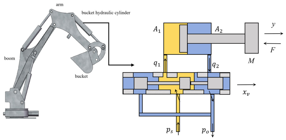
The actuator of a hydraulic excavator is driven by a valve-controlled asymmetric hydraulic cylinder [29], and its dynamic characteristics exhibit significant bidirectional asymmetry. In establishing the mathematical model of the hydraulic system for the working device of the hydraulic excavator, the following simplified assumptions are adopted: the oil supply system is treated as an ideal constant-pressure source; the oil supply pressure ps is assumed constant, the oil return pressure po is approximately zero, and the electromagnetic proportional valve is dynamically simplified to a static gain. Additionally, the flow through the valve port is assumed to be turbulent, the bulk modulus of hydraulic oil is considered constant, and the distributed parameter effects of hydraulic pipelines and the inertia of oil mass are neglected. The asymmetric valve-controlled hydraulic cylinder is modeled accordingly, and the schematic diagram is presented in Figure 2.
In the hydraulic excavator system, the response speed of the main valve is much higher than that of other hydraulic systems, ignoring the main valve dynamics, and simplifying the control input voltage u is proportional to the position of the valve core [30].
x v = K z u f
where xv denotes the piston displacement of the main valve, Kz denotes the amplification factor, and u is the input voltage.
The turbulence assumption is used for the flow of the asymmetric hydraulic cylinder valve port. The pressure of the rodless cavity is p1, the pressure of the rod cavity is p2, and the throttling equation under the extension condition is:
Q 1 = C d w x v 2 ρ ( p s p l )
Q 2 = C d w x v 2 ρ p 2
where Cd denotes the flow coefficient, w denotes the valve port area gradient, ρ denotes the oil density, ps denotes the oil supply pressure, pl denotes the load pressure, A1 denotes the rodless cavity area, and A2 denotes the rod cavity area.
Due to the continuity of piston motion, the volume flow of the two chambers satisfies:
p l = p 1 n p 2 n = A 1 A 2 = Q 1 Q 2
Combining Equations (13)–(15), the explicit expression of the pressure [22,31] of the two chambers with respect to the oil supply pressure and the load pressure is obtained:
p 1 = p s + n p l 1 + n p 2 = p s p l n ( 1 + n )
Substituting Equation (16) into Equation (13), the display relationship of the load flow curve under the extension condition can be obtained:
Q L ext = C d w x v 2 ρ n ( p s p l ) 1 + n
The throttling equation under the retraction condition is:
Q 1 = C d w x v 2 ρ p 1
Q 2 = C d w x v 2 ρ ( p s p 2 )
The continuity of piston motion satisfies the following formula:
p s p 2 = n 2 p 1 n = A 2 A 1 = Q 2 Q 1
Joint Form (18)–Form (20) gets:
p 2 = p s n p l 1 + n p 1 = p s + p l n ( 1 + n )
Substituting into the second formula of Equation (19), the load flow under retraction condition is obtained:
Q L ret = C d w x v 2 ρ p s p l n ( 1 + n )
Comparing the load flow under the extension and retraction conditions, under the same valve opening xv and the same pressure drop p s p l …, the flow gain ratio of the extension/retraction condition is:
Q L ext Q L ret = n
This ratio indicates the asymmetry of the velocity gain. In the retraction phase, the velocity is n times that of the extension phase under the same control input due to the small A2.
In order to facilitate the design of the subsequent controller, the nonlinear dynamic model of the excavator manipulator needs to be transformed into the form of a state space equation. The state space expression is not only beneficial to the stability analysis and control rate design of the control system, but also can intuitively describe the dynamic behavior of the system. The state variable z = [ y T , y ˙ T , p l T ] T is selected, where y is the displacement of the hydraulic cylinder piston, y ˙ is the velocity of the piston, and pl is the equivalent load pressure.
From the kinematic relationship:
z ˙ 1 = z 2
According to the force balance equation [31]:
A 1 p 1 A 2 p 2 = m t y ¨ + F L
The speed dynamic:
z ˙ 2 = A 1 z 3 F L m t = A 1 m t z 3 1 m t w ( t )
Among them, mt denotes the equivalent mass of the piston, FL denotes the external load force acting on the piston, and ω ( t )   =   F L denotes the time-varying external load regarded as a bounded disturbance.
The continuity equation and the load pressure definition are substituted into the two-cavity flow expression to obtain the pressure dynamics:
Stretching condition:
z ˙ 3 = 2 β e V eq C d w K z u f 2 ρ · n ( p s z 3 ) 1 + n A 1 z 2 q leak ( z 3 )
retraction phase:
z ˙ 3 = 2 β e V eq C d w K z u f 2 ρ · p s z 3 n ( 1 + n ) A 1 z 2 q leak ( z 3 )
where V eq = V 1 + n 2 V 2 denotes the equivalent volume and q leak = C i ( p 1 p 2 ) + C o p 1 , 2 denotes the leakage flow.
The state space equation is written as a standard control-affine form:
z ˙ = f ( z , σ ) + g ( z , σ ) u f + d ( t )
z ˙ = z 2 A 1 m t z 3 2 β e A 1 V eq z 2 + φ ( z 3 , σ ) + 0 0 ψ ( z 3 , σ ) u f + 0 ω ( t ) m t 0
Here, σ denotes the condition identifier, φ ( z 3 , σ ) = 2 β e V eq q leak ( z 3 ) denotes the state-depend ent nonlinear function, and ψ ( z 3 , σ ) = 2 β e C d w K z V eq 2 ρ · γ ( σ ) ( p s z 3 ) 1 + n denotes the direction-dependent control gain.

3. Design of Event-Triggered Asymmetric Gain RBF-PID Controller

3.1. The Overall Structure of the Controller

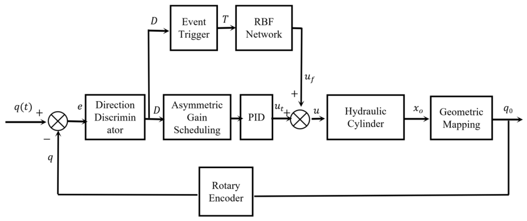
The proposed ET-AGRP controller comprises five functional modules: direction identification, asymmetric gain scheduling, PID, event-triggered sparse RBF, and control synthesis, with the overall architecture depicted in Figure 3. The direction identification module determines the extension/retraction states of hydraulic cylinders in real time from joint angular velocities and generates a directional signal D. This signal drives the asymmetric gain scheduling module to differentially configure PID parameters and establish direction-dependent thresholds for the event-triggered module. The event-triggered module determines whether to activate RBF network weight updates based on the tracking error variation and the current directional threshold; the six-node RBF network outputs an adaptive compensation term uf. The output u of the asymmetric gain scheduling module and the RBF compensation term uf are aggregated through a synthesizer to constitute the total control command ut, which actuates the asymmetric hydraulic cylinders via the kinematic mapping of the mechanism to achieve joint trajectory tracking.

3.2. Design of an Asymmetric Control Mechanism Based on Velocity Direction

The asymmetric dynamic characteristics of the joint actuators of a hydraulic excavator are fundamentally governed by the difference in the effective areas of the two chambers of the hydraulic cylinder and the coupling effect of the gravity load [32,33,34]. Owing to the distinct geometric installation poses of the boom, arm, and bucket, the mapping relationship between the telescopic motion and the gravity direction exhibits significant heterogeneity. Consequently, it is imperative to establish a differentiated control mechanism based on real-time motion direction recognition to achieve the adaptive dynamic reconstruction of parameters. In this paper, the working condition of the hydraulic cylinder Is identified by real-time monitoring of the joint angular velocity polarity, and the hierarchical asymmetric control strategy is triggered accordingly. Direction-dependent parameter space constraints and rate-of-change limits are imposed to accommodate the heterogeneous characteristics, such as the reduction in gravity superposition during boom retraction and the increase in gravity overcoming during arm and bucket retraction, thereby suppressing the speed loss caused by gravity coupling while ensuring response sensitivity.
Accurate condition discrimination is the prerequisite for implementing asymmetric control. Assuming that the measured value of the joint angle at the kth sampling instant is θ ( k ) and the sampling period is T s , the raw angular velocity signal is obtained through the differential operation:
v ( k ) = θ ( k ) θ ( k 1 ) T s  
To suppress the high-frequency jitter induced by measurement noise and load disturbance, a first-order low-pass filter is employed to smooth the angular velocity signal:
v f ( k ) = α v v ( k ) + ( 1 α v ) v f ( k 1 )  
In the above equation, α v ( 0 , 1 ) denotes the filtering coefficient, which is typically set in the range of 0.05 to 2 to balance the requirements of response sensitivity and noise suppression.
Based on the smoothed angular velocity signal v f ( k ) , a direction discrimination logic with hysteresis characteristics is constructed to prevent the oscillation of working conditions near zero speed. The speed threshold v t h > 0 and the hysteresis width Δ v are specified, and the direction identifier σ ( k ) { 1 , 1 } is defined to correspond to the extension and retraction conditions:
σ ( k ) = 1 , if   v f ( k ) < v t h     ( σ ( k 1 ) = 1     v f ( k ) < Δ v ) 1 , if   v f ( k ) > v t h     ( σ ( k 1 ) = 1     v f ( k ) > Δ v ) σ ( k 1 ) , otherwise
For the boom joint, the retraction motion corresponds to the superposition effect of the descending gravity of the entire machine, which causes the system to exhibit the characteristics of “low damping and easy acceleration.” The uplift corresponding to the extension movement must overcome gravity to perform work. Therefore, a significantly asymmetric gain limitation is implemented:
K p [ 60 , 135 ] , σ = 1 [ 20 , 100 ] , σ = 1  
For the arm and bucket joints, the coupling relationship between the direction of motion and gravity is opposite to that of the boom. The retraction stage corresponds to the upward retraction. It is necessary to overcome the weight of the connecting rod and the load gravity, and the system exhibits the characteristics of “high damping and slow response.” The extension stage corresponds to the downward expansion. For such heterogeneous characteristics, a relatively mild but direction-differentiated parameter scheduling is implemented:
Arm joint:
K p [ 15 , 90 ] , σ = 1 [ 12 , 60 ] , σ = 1  
Bucket joint:
K p [ 35 , 100 ] , σ = 1 [ 25 , 85 ] , σ = 1
To mitigate the risk of integral saturation induced by gravity coupling, a direction-dependent integral separation strategy is adopted, and the integral term I ( k ) is formulated as:
I ( k ) = I ( k 1 ) + γ i ( σ ) · K i · e ( k ) · T s  
In the formula, γ i ( σ ) denotes the direction-dependent integral gain coefficient:
γ i ( σ ) = 1.0 , σ = 1 0.5 , σ = 1  
At the same time, the direction-dependent integral saturation limit is set:
| I ( k ) | I max σ = 800 , σ = 1 600 , σ = 1  
For the differential term, the speed damping needs to be strengthened in the retraction stage to suppress gravity acceleration or prevent overshoot, especially for the boom retraction condition:
K d σ = 1 K d min , ret = 0.5
The gain boundaries and saturation parameters for each joint in Equations (30)–(36) are determined through a systematic procedure integrating physical-constraint estimation and step-response parameter sweeping. The initial feasible interval of the proportional gain Kp is first established by estimating the directional driving torques and gravitational load torques based on the hydraulic cylinder asymmetric area ratio n, the system supply pressure Ps, and the respective joint moment arms. The upper bound of Kp is then identified via step-response sweeping on the linearized valve-controlled cylinder model, adopting half the critically stable gain as a safety margin. Finally, the parameters γ i σ , I max σ , and K d min , r e t are configured according to the anti-windup and damping suppression requirements for gravity-assist and gravity-resist directions.
Through the aforementioned asymmetric control mechanism based on velocity direction identification, the system achieves dynamic parameter reconstruction tailored to the gravity coupling characteristics of each joint. The boom adopts a highly conservative strategy during retraction to suppress descent acceleration. The arm and bucket operate with moderate gains, and the rate of change is strictly constrained during retraction to prevent response lag or overshoot during upward folding. This mechanism establishes the foundational framework for subsequent non-gain-scheduled and RBF adaptive compensation strategies.

3.3. Event-Triggered Sparse RBF Network Design

The velocity-direction-based asymmetric control mechanism improves bidirectional dynamic response by imposing fixed parameter space constraints. However, fixed architectures struggle to guarantee adaptive accuracy when confronted with load variations and unmodeled dynamics. Although the standard RBF neural network possesses the universal approximation property [35], there is a structural contradiction between its cycle-intensive computing and the limited computing power of the embedded platform. To this end, this paper constructs an event-triggered sparse RBF network and optimizes the trade-off between adaptive accuracy and computational load by establishing a condition-aware non-uniform sampling mechanism and a six-node sparse topology.
The sparse RBF network adopts a three-layer feed forward network structure. The three-dimensional input vector is composed of system error e, error change rate e ˙ and reference instruction r. The network input vector x ( k ) is as follows:
x ( k ) = [ e ( k ) , e ˙ ( k ) , r ( k ) ] T
where e ˙ ( k ) = ( e ( k ) e ( k 1 ) ) / T s .
Through sensitivity analysis, the hidden layer is configured with six radial basis neurons employing Gaussian activation functions. The Gaussian basis function for the j-th hidden-layer node is given by:
h j ( x ) = exp x c j 2 2 b j 2 , j = 1 , 2 , , 6  
In the formula, c j = [ c j 1 , c j 2 , c j 3 ] T denotes the center vector of the jth basis function, which is optimized in the effective workspace according to the motion range of each joint. b j   denotes the base width parameter to ensure local sensitivity and coverage uniformity.
The output layer is the online estimation of the Jacobian information of the controlled object:
J ^ ( k ) = j = 1 6 w j ( k ) h j ( x ( k ) ) = w T ( k ) h ( x ( k ) )  
In the formula, w ( k ) = [ w 1 ( k ) , , w 6 ( k ) ] T denotes the weight vector of the output layer, h ( x ) = [ h 1 ( x ) , , h 6 ( x ) ] T . The Jacobian estimate J ^ = y / u characterizes the sensitivity of the control input to the system output and provides gradient information for PID parameter adaptation.
Due to the time-varying parameters and load disturbances in the hydraulic system, it is difficult to guarantee the accuracy of Jacobian estimation for static weights, and an online adaptive law of weights is needed. Therefore, the Jacobian identification error is constructed by using the input and output data of the system, and the dynamic optimization of the weights is realized by minimizing the error. The following defines the control increment and output increment at adjacent sampling times:
Δ u ( k ) = u ( k ) u ( k 1 ) , Δ y ( k ) = y ( k ) y ( k 1 )  
When | Δ u ( k ) | > ϵ u , the true Jacobian is estimated to be:
J ˜ ( k ) = Δ y ( k ) Δ u ( k )  
This value represents the local dynamic sensitivity between input and output in the actual control process. The identification error between the network estimate J ^ ( k ) and the real estimate J ˜ ( k ) is constructed:
e J ( k ) = J ˜ ( k ) J ^ ( k )  
To minimize the error, the performance index function is defined:
E ( k ) = 1 2 e J 2 ( k )  
According to the gradient descent principle, the weight adjustment direction aligns with the negative gradient of the performance index:
Δ w j ( k ) = η w E w j  
In the formula, η w denotes the learning rate. By taking the partial derivative of Equation (52) and substituting it into Equations (46) and (51), we can obtain:
E w j = e J ( k ) e J w j = e J ( k ) h j ( x ( k ) )  
The adaptive weight update law is thereby derived as follows:
w j ( k + 1 ) = w j ( k ) + η w e J ( k ) h j ( x ( k ) )
In the formula, η w denotes the learning rate to determine the convergence rate of the weight; h j ( x ( k ) ) is the hidden layer output, and g represents the degree of local activation in the input space. The adaptive mechanism enables the network to update its Jacobian estimation online in response to actual control effects, thereby furnishing accurate gradient information for PID parameter tuning and effectively compensating for the limited adaptability of asymmetric gain mechanisms to temporal parameter variations.
In order to avoid the above update calculation in each control period, an event triggering mechanism based on error variation is established. The control period is set to T s , and the system tracking error at time k is e ( k ) . The trigger time sequence { k t } t = 0 is defined, and its trigger logic is determined by the error variation and the direction dependence threshold. The triggering discriminant function is constructed as follows:
ξ ( k ) = | e ( k ) e ( k t ) | δ e ( σ ( k ) )  
In the formula, e ( k t ) denotes the memorized error value at the last trigger instant k t , and δ e represents the direction-dependent error threshold. The trigger instant is updated to k t + 1 = k when ξ ( k ) > 0 or the forced trigger count N ( k ) N max is satisfied.
The threshold δ e implements differentiated configuration according to asymmetric control requirements. The boom needs to respond quickly to overcome the strict threshold of gravity setting:
δ e ( 1 ) = 0.2  
Under the retraction condition, gravitational superposition decreases; therefore, the computational overhead is substantially suppressed by adopting a loose threshold:
δ e ( 1 ) = 1.2  
When the arm and bucket retract, a moderate threshold is maintained to overcome the increased gravitational effect:
δ e ( 1 , arm ) = 0.5 δ e ( 1 , bucket ) = 0.8
The trigger mechanism is embedded in the weight update law, and network calculation and weight correction are performed only at the trigger moment:
w j ( k + 1 ) = w j ( k ) + τ ( k ) · η w e J ( k ) h j ( x ( k ) )  
At the same time, the weight saturation constraint is implemented to prevent parameter drift:
w j ( k ) = sat w j ( k ) , 2.0 , 2.0  
Through the integration of event-triggered mechanisms with sparse RBF networks, the system utilizes a six-node RBF architecture to perform online fine compensation for time-varying parameters during boom extension and bucket/arm retraction phases, while transitioning to low-computational-overhead gain modes during boom retraction and bucket/arm extension phases, thereby achieving an asymmetric optimal trade-off between adaptive accuracy and computational efficiency.

3.4. Asymmetric Gain Scheduling Mechanism

This section introduces an expert-knowledge-based nonlinear gain scheduling mechanism as the front-end stage of parameter adaptation, generating baseline corrections for PID parameters that hierarchically synergize with the fine compensation delivered by the RBF network to constitute graded adaptation. At the implementation level, the mechanism employs a deterministic algebraic mapping of normalized tracking error E(k) and its rate of change EC(k); this analytical formulation reduces the per-cycle computational overhead to a magnitude comparable to that of conventional PID, thereby satisfying the real-time constraints of embedded platforms.
The tracking error e(k) and its difference ec(k) are adopted as scheduling inputs. To unify the input domain and facilitate the scheduling rules, a normalization mapping is implemented:
  E ( k ) = sat k e · e ( k ) , 1 , 1   E C ( k ) = sat k e c · e c ( k ) , 1 , 1  
In the formula, k e and k e c are quantization factors, sat ( · ) denotes the saturation function, which ensures the normalized characteristic quantity E , E C [ 1 , 1 ] and facilitates the standardization of subsequent gain scheduling.
According to the direction identification σ ( k ) { 1 , 1 } identified in Section 3.2, the differential reasoning rules of the extension and retraction conditions are established, respectively, to realize the asymmetric parameter scheduling.
Predicated on the motion-direction identifiers identified in Section 3.2, differentiated scheduling protocols are established for extension and retraction strokes, thereby enabling asymmetric parameter adjustment. During upward boom motion in extension operations and upward arm and bucket motions in retraction operations, a high-gain rapid-response strategy is employed to counteract gravitational loading. The bucket joint serves as a representative case.
Δ K p f = 1.2 · E · 1 0.5 | E C |   Δ K i f = 0.2 · 1 | E | · ( sign ( E ) )   Δ K d f = 0.2 · E C  
In the formula, Δ K p f denotes in the same direction as the error E to accelerate the elimination of deviation, and at the same time, the proportional gain is automatically suppressed by the ( 1 0 . 5 | EC | ) term when the error changes greatly to prevent overshoot. The integral correction Δ K i f weakens the integral effect to avoid saturation when the error is large, and eliminates the static error according to the reverse adjustment of the symbol when the error is small. The differential correction Δ K d f is reversed to the error change rate to provide damping.
During boom descent in the retraction phase and arm/bucket descent in the extension phase, the system encounters compounded gravity-assist effects, necessitating an extremely conservative tuning strategy. For the bucket joint in particular, the proportional gain correction is drastically attenuated:
Δ K p f = 0.02 · E   Δ K i f = 0   Δ K d f = 0  
At this tuning point, the integral and differential compensation terms are annihilated while the proportional correction coefficient is attenuated to 0.02, yielding extremely conservative outputs from the gain scheduling layer. Constrained non-zero outputs are preserved for the boom and arm joints during retraction strokes in accordance with their inertial characteristics, with smoothing coefficients imposed to suppress parameter chattering. The event-triggered RBF network is explicitly deactivated during retraction phases. Accordingly, the controller degenerates to the baseline PID configuration to preserve stability during boom retraction and extension strokes of the arm and bucket.
Once the gain scheduling layer generates the baseline correction term Δ K f , hierarchical superposition is performed with the gradient correction Δ K R B F delivered by the RBF network elaborated in Section 3.3. During extension strokes, when the event-triggering flag τ ( k ) = 1 , the synergistic correction is executed:
K ( k ) = K ( k 1 ) + Δ K f ( k ) + η ( σ ) · Δ K R B F ( k )  
Δ K f = [ Δ K p f , Δ K i f , Δ K d f ] T
Here, η ( σ ) denotes the scaling factor.
When retracting the working condition or τ ( k ) = 0 , the control strategy degenerates into conventional gain scheduling:
K ( k ) = K ( k 1 ) + Δ K f ( k )  
This hierarchical synergistic mechanism ensures that the gain scheduling layer furnishes rapid coarse adjustment grounded in expert heuristics, whereas the RBF layer contributes data-driven fine optimization. Through directional identifiers and event-triggered coordination, the two layers achieve asymmetric fusion, effectively reconciling transient responsiveness with steady-state precision.

3.5. System Stability Analysis

To validate the closed-loop stability of the proposed event-triggered asymmetric gain RBF-PID control strategy [36], this section establishes the uniform ultimate boundedness (UUB) of tracking errors and parameter estimation errors based on Lyapunov stability theory [37]. Accounting for the nonlinear dynamics of hydraulic servo systems, the intermittent update characteristics introduced by the event-triggering mechanism, and the nonlinear mapping of the asymmetric gain scheduling mechanism, a composite energy function is constructed to demonstrate system stability under parametric time variation and bounded disturbances. Both the gain scheduling layer and the RBF network are discretely updated with period TS on the embedded platform, with control outputs maintained via zero-order hold (ZOH) after D/A conversion. To rigorously bridge continuous-time dynamics and discrete-time implementation, the input error induced by ZOH and gain chattering are incorporated into the aggregated disturbance term, drawing upon Nesic and Teel’s sufficient conditions for input-to-state stability (ISS) small-gain theorem [38] for sampled-data systems. As revealed by the electro-hydraulic servo system model in Section 2, hydraulic actuators are subject to physical bandwidth constraints, with state variation rates bounded within compact set Ω x ; when the sampling period is sufficiently small relative to this local dynamic, the decay characteristics of the continuous-time Lyapunov function remain valid within the sampling interval, and the UUB conclusion of Equation (68) can be directly extended to ZOH implementation [39,40]. Consequently, merely relaxing the disturbance upper bound ρ to absorb the sampling hold error, the uniform ultimate boundedness of the system remains rigorously valid.
Based on the dynamic model of the electro-hydraulic servo system in Chapter 2, the control affine form is considered:
x . = f ( x ) + g ( x ) u + d ( t )  
In the formula, x denotes the system state vector, u denotes the control input, f ( · ) and g ( · ) are continuous, differentiable nonlinear functions, d ( t ) denotes the lumped disturbance, and is assumed to be bounded d ( t ) d max .
For the trajectory tracking problem, the tracking error e ( t )   =   θ d ( t )   θ ( t ) is defined, where θd denotes the desired trajectory and θ denotes the joint angle output. From the system output equation h ( x ) and the PID control law u = K p e + K i 0 t e ( τ ) d τ + K d e ˙ , the error dynamics can be expressed as:
e ˙ = θ ˙ d J ( x ) u δ ( x , t )  
In the formulation, J ( x ) denotes the system Jacobian, and δ ( · ) denotes the lumped uncertainty including disturbance and modeling error.
Assumption 1.
In the compact set  Ω x , there exists an optimal weight  w *  such that the RBF network can approach the real Jacobian with the same accuracy  ε J  [41], that is:
J ( x ) = w * T h ( x ) + ε J ( x ) , | ε J | ε max
In the formula, h ( x ) denotes the Gaussian basis function vector and ε max denotes the upper bound of the approximation error.
Assumption 1 provides an upper bound ε max on the RBF network approximation error with respect to the true Jacobian; however, the specific magnitude of this bound directly governs the engineering significance of the ultimate tracking accuracy μ e . Accordingly, a quantitative calibration of the six-node network adopted herein is indispensable. The RBF network input is defined as x = [ e , e ˙ , r ] T . Under excavator trajectory-tracking conditions, the admissible variation ranges of each component within the compact set Ω x are prescribed by | e | e max , | e ˙ | e ˙ max , and | r | r max , respectively. The centers c j ( j = 1 , , 6 ) of the six Gaussian basis functions are strategically positioned at key characteristic points selected from typical operating conditions within Ω x , with the kernel width set to σ = 50 . The six-node configuration inherently suffers from limited coverage density in the three-dimensional input space. To verify that the approximation error remains controllable within actual operating regions, this paper conducts calibration through dense sampling as follows.
By densely sampling N s grid points within this compact set and computing the true Jacobian via the analytical dynamic model presented in Chapter 2, the optimal weight vector w * is solved to minimize the mean square error between the network output w * T h ( x ) and the true Jacobian, yielding the maximum absolute approximation error ε max = max x Ω x J ( x ) w * T h ( x ) . The calibration results indicate that ε max accounts for approximately 97–104% of the Jacobian magnitude, reflecting that the multi-valued gain mapping induced by asymmetric cylinder chamber characteristics at identical operating points has exceeded the global offline fitting capacity of the six-node Gaussian basis functions. Nevertheless, this magnitude remains a finite constant, and the approximation boundedness within the compact set μ e postulated in Assumption 1 remains strictly valid; it merely renders the numerical value of the ultimate error bound Ω x relatively conservative. The collaborative interaction between the event-triggered online adaptation mechanism and the underlying PID control law compresses this conservative theoretical bound to an engineering-acceptable range.
Therefore, despite the coverage gaps of the six-node network at peripheral regions of the input space, the working-device Jacobian exhibits multi-valued nonlinearities within typical excavator operating regions due to hydraulic asymmetric characteristics. This configuration, combined with event-triggered sparse updates and the underlying PID control law, provides local adaptive corrections for the system, while the ultimate tracking accuracy is guaranteed by the underlying PID control law. Should further improvement in approximation accuracy or expansion of the operating range be required, the node count may be increased subject to the computational resource constraints of the embedded platform, albeit at the cost of elevated event-triggering frequencies and computational overhead.
Assumption 2.
Predicated on the motion-direction identifiers in Section 3.2 and the asym metric gain-scheduling mechanism in Section 3.4, the PID gains and gain-scheduling correction terms are uniformly bounded. Through the saturation mapping of Equation (53) and the deterministic algebraic rule of Equation (54), the gain-scheduling outputs satisfy  | Δ K p f | Δ K p , max f ,  | Δ K i f | Δ K i , max f , and  | Δ K d f | Δ K d , max f ; consequently, there exist positive constants  K _ p , K ¯ p  such that  K _ p K p ( t ) K ¯ p , with  K i ( t ) ,   K d ( t )  being similarly bounded.
Considering the tracking error, integral error, and RBF weight estimation error, the following positive definite Lyapunov function candidates are constructed:
V ( t ) = 1 2 e 2 ( t ) + K i ( t ) 2 0 t e ( τ ) d τ 2 + 1 2 η w w ˜ T ( t ) w ˜ ( t )  
In the formula, w ˜ = w * w denotes the weight estimation error and η w denotes the learning rate. Derivation of time along the system trajectory:
V ˙ = e e ˙ + K i e e d τ + K ˙ i 2 e d τ 2 1 η w w ˜ T w .  
Substituting the error dynamics and PID control law, and considering w . = τ ( t ) η w e J h , we can get:
V ˙ = e y ˙ d J u δ + K i e e d τ τ ( t ) w ˜ T e J h + K ˙ i 2 e d τ 2  
In order to deal with the event trigger item, it is discussed in two cases. The RBF network is updated at the trigger time. Substitute J = J ^ + w ˜ T h + ε J and e J = J ˜ J ^ J J ^ = w ˜ T h + ε J , assuming that the difference quotient estimation h is close enough to the real value into Equation (68), and sort out the control input item:
V ˙ = K p e 2 K d e e ˙ + e y ˙ d K i e e d τ δ ε J u + K i e e d τ w ˜ T h h T w ˜ w ˜ T h ε J + K ˙ i 2 e 2
The cross terms in Equation (65) are treated via Young’s inequality 2 a b a 2 / γ + γ b 2 ( γ > 0 ). Scaling coefficients γ 1 , γ 2 , γ 3 > 0 are assigned to the cross terms containing e, with quadratic portions absorbed into the e 2 -term coefficients and bounded disturbances relegated to constant terms. Rearrangement yields the e 2 -term coefficient λ 1 = K p K d 2 4 γ 1 1 2 γ 2 1 2 γ 3 . Given the proportional-gain lower bound K _ p > 0 in Assumption 2, sufficiently small γ i are chosen such that K _ p > K d 2 / ( 4 γ 1 ) + j = 2 3 1 / ( 2 γ j ) , ensuring λ 1 > 0 . The weight-estimation error coefficient λ 2 stems from the term w ˜ T h h T w ˜ = ( w ˜ T h ) 2 in Equation (65); its positivity is guaranteed by the non-zero boundedness of Gaussian basis function h ( x ) within compact set per Assumption 1. Since there exists h min > 0 satisfying h ( x ) h min , it follows Ω x that ( w ˜ T h ) 2 h min 2 w ˜ 2 , whence λ 2 = h min 2 > 0 . The integral-term coefficient λ 3 = κ i / 2 follows directly from the bounded parameter-variation rate | K ˙ i | κ i in Assumption 2. Consequently, positive constants λ 1 , λ 2 , λ 3 exist such that Equation (66) holds. For the highly conservative gain scenario under retraction conditions addressed in Section 3.4, numerical verification is performed using the parameter set of the hydraulic excavator working device studied herein. With appropriately selected scaling coefficients γ 1 , γ 2 , γ 3 and substitution of the lower-bound total-gain values under retraction, all computed coefficients λ 1 , λ 2 , λ 3 are positive, thereby guaranteeing that the error energy remains dissipative under this condition. The verification results are summarized in Table 2, λ 2 = h min 2 > 0 which is uniquely determined by the RBF network nodes and is independent of operating conditions; it λ 3 = κ i / 2 is computed from the global upper bound κ i of the variation rate of integral gain K i ( t ) derived from simulation data, covering the complete phases of extension, retraction, and zero-position transition, so that identical values apply to the same joint across different conditions. This global upper-bound selection satisfies the uniform boundedness requirement on parameter variation rates mandated by the Lyapunov stability proof.
V ˙ λ 1 e 2 λ 2 w ˜ 2 + λ 3 e d τ 2 + ρ  
In ρ = 1 2 λ 1 ( y ˙ d , max + d max + ε max u max ) 2 + ε max 2 4 λ 2 denotes the upper bound of the lumped per-turbation.
At non-triggering instants, the weights remain frozen, and the Jacobian estimate is held at its last triggered value J ^ l a s t . Define the estimation error as J ˜ l a s t = J J ^ l a s t , which is decomposed into the approximation error at the previous triggering instant and the state drift accumulated over the inter-event interval: J ˜ l a s t = [ J ( x ( t k ) ) J ^ l a s t ] + [ J ( x ( t ) ) J ( x ( t k ) ) ] . The first term represents the RBF network approximation error at the triggering instant, whose upper bound is given ε max by Assumption 1. For the second term, Assumption 1 guarantees that it J ( x ) is continuously differentiable on the compact set Ω x and satisfies the Lipschitz condition. The event-triggering condition | e e τ | δ e ensures that the system state does not deviate significantly from the operating point at the last trigger during the inter-event interval; hence, J ( x ( t ) ) J ( x ( t k ) ) L J δ e . Incorporating the limited-bandwidth characteristic of the hydraulic system as a constraint on the state variation rate yields | J ˜ l a s t | L J δ e + ε max , upon which Equation (64) degenerates to:
V ˙ λ 1 e 2 + ρ  
Furthermore, pursuant to the asymmetric gain scheduling mechanism elaborated in Section 3.4, the event-triggered RBF network is explicitly suspended during retraction strokes, whereby the system degenerates into pure gain-scheduled PID control. During this phase, the network weights are frozen and the triggering condition ceases to be evaluated; the control input is generated exclusively by the gain scheduling layer. Owing to Assumption 2, which ensures bounded gains throughout this phase, the closed-loop system satisfies input–output stability, and the attenuation of error energy is guaranteed by standard time-varying PID theory. Moreover, this phase is exempt from Zeno behavior risks. At event-triggering instants, the RBF network weights are updated according to w . = τ ( t ) η w e j h   , engendering a finite jump in the third term of Equation (62) at the switching instant. By Assumption 1, the basis function vector h ( x ) remains bounded within the compact set Ω x , and the learning rate η w is a design constant; consequently, the weight update Δ w   is finite. Meanwhile, the triggering condition | e e τ | δ e ensures that the system state at the triggering instant does not deviate markedly from the condition at the preceding triggering instant. In conjunction with the bounded error variation rate in Equation (67), it follows that the Lyapunov function jump Δ V ( t k ) = V ( t k + ) V ( t k ) at the switching instant is finite. Since the uniform ultimate boundedness conclusion established in this work permits finite jumps of the Lyapunov function at discrete update instants, and both Equations (66) and (67) guarantee the decay trend of error energy within triggered and non-triggered intervals, the switching process does not undermine the practical stability of the closed-loop system. Accordingly, the Lyapunov function jump Δ V ( t k ) induced by mode switching is finite, and Equations (66) and (67) guarantee the decay trend of error energy in both triggered and non-triggered intervals; the switching process preserves closed-loop stability and does not induce sustained oscillations. This conclusion permits finite jumps of the Lyapunov function at discrete update instants, conforming to the definition of practical stability within the sampled-data system ISS small-gain theorem framework.
Synthesizing both scenarios, define λ = min { λ 1 , λ 1 } . From Equation (62), it follows that V ( t ) 1 2 e 2 ( t ) , whence λ e 2 2 λ · 1 2 e 2 . Accounting for the boundedness of the integral term and weight estimation errors, Equations (66) and (67) are consolidated as:
V ˙ 2 λ V + β
where β = ρ ¯ + λ · 1 2 η w w ˜ max 2 + λ · K ¯ i 2 E max 2 is a constant, with w ˜ max being the upper bound on the weight estimation error and E max = max t 0 t e ( τ ) d τ the upper bound on the integral error. The existence of both bounds is guaranteed by the compact set Ω x in Assumption 1 and the parameter boundedness in Assumption 2.
Solving this differential inequality yields:
V ( t ) V ( 0 ) e 2 λ t + β 2 λ ( 1 e 2 λ t )  
At that time, t , V ( t ) β / ( 2 λ ) . Therefore, the tracking error and the weight estimation error are ultimately uniformly bounded:
lim sup t | e ( t ) | β λ μ e  
The size of the bounded set depends on the disturbance upper bound d max , the RBF ap proximation error ε max , the trigger threshold δ e and the minimum proportional gain. Because the asymmetric control mechanism ensures that the gain of the extended condition is large enough, although the gain of the retracted condition is low, the gravity-assisted motion reduces the tracking accuracy requirements, and the system meets the stability requirements in the full operating range.
In order to ensure that the event triggering mechanism does not lead to infinite triggering, the lower bound of the triggering interval needs to be verified. From the error dynamic Formula (64) and Assumptions 1 and 2, the error change rate satisfies:
| e ˙ | L e | e | + L u | u | + d max + y ˙ d , max v max
Herein, the theoretical upper bound on v max is contingent upon the control input, which is in turn influenced by adaptive gains, thereby engendering a circular dependency between the gain and the triggering frequency. To circumvent this circularity, the inherent physical velocity limit of the hydraulic actuator is introduced. As elucidated by the electro-hydraulic servo system model in Section 2, the rated flow of the servo valve and the effective area of the hydraulic cylinder constrain the joint angular velocity to a physical saturation bound | q ˙ | q ˙ max , phys , which is dictated exclusively by intrinsic hardware characteristics and remains completely decoupled from control gains and event-triggering logic. Since e = y d y , it follows that | e ˙ | = | y ˙ d q ˙ | y ˙ d , max + q ˙ max , phys v phys , where v phys is a finite constant dependent solely on the desired trajectory and hydraulic hardware, independent of the triggering mechanism. Consequently, substituting v phys for the gain-dependent v max in Equation (67) furnishes a conservative estimate, and the inter-trigger interval satisfies.
T min = δ e ( σ ) v max > 0
Since the triggering threshold δ e ( σ ) > 0 is positive and bounded, and v p h y s is finite, T min admits a strictly positive lower bound, thereby precluding Zeno behavior. Furthermore, as established in Section 3.4, the RBF network is suspended during the retraction phase, and the triggering condition is not evaluated in this interval. Consequently, the foregoing Zeno-exclusion argument applies exclusively to the extension phase with active RBF adaptation, ensuring the physical realizability of the event-triggered mechanism on embedded platforms.
Regarding potential oscillations induced by mode switching, this study addresses the issue through three hierarchical mitigation measures: (1) Assumption 2 ensures that the asymmetric gain scheduling output K p f satisfiest | K p f |     K p , max f , wherein such boundedness constrains the gain jump amplitude at switching instants, thereby precluding drastic variations in control inputs; (2) as implied by Equations (67) and (68), hydraulic actuators exhibit physical velocity limits v p h y s , and the event-triggering interval admits a strictly positive lower bound T min ; the inherent finite-bandwidth characteristics of the system thereby function as a natural low-pass filter against high-frequency components introduced during switching and event updates; (3) directional discrimination employs Schmitt hysteresis to circumvent frequent directional chattering in the vicinity of zero velocity. Collectively, the control input jumps triggered by mode switching are confined within bounded ranges, while the physical inertia of the hydraulic system further attenuates oscillation risks. This stability conclusion furnishes theoretical guarantees for the synergistic operation among the asymmetric control mechanism, the event-triggered sparse RBF network, and gain-scheduling adaptation, substantiating the robustness and implementability of the proposed strategy in hydraulic excavator trajectory tracking control.

4. Simulation Verification and Performance Analysis

4.1. Simulation Platform Construction

The simulation platform was established in the MATLAB R2020b/Simulink environment, encompassing the kinematic model of the excavator manipulator, the hydraulic actuator model, and the control system. The RBF neural network adopts the Gaussian basis function. The centers of the six hidden-layer neurons were uniformly distributed along the error dimension within the normalized input space [−1, 1]3, and the basis-function width was set to 0.5. The weight of the network is updated online by the gradient descent method of the driving term. The network weights were updated online via gradient descent driven by the tracking-error term. A learning rate η of 0.1 and an inertia coefficient α of 0.05 were adopted to suppress high-frequency oscillations and accelerate convergence. Concurrently, a projection operator confined the weights to the interval [−2, 2] to prevent parameter drift. The simulation solver sets a fixed step size for a total simulation of 60s, using the ode23t algorithm, and the controller sampling period and the simulation step size are synchronized to ensure real-time performance.

4.2. Trajectory Tracking Performance Analysis

To verify the effectiveness of the proposed event-triggered asymmetric-gain RBF-PID control strategy for operational trajectory tracking, an integrated simulation model of the hydraulic excavator working device was constructed in the MATLAB/Simulink environment. A composite sinusoidal reference trajectory, encompassing diverse variable-velocity motion regimes and periodic directional reversals, was formulated; its mathematical expression is presented in Equation (73).
In the simulation, the tracking accuracy and robustness of the controller for each joint trajectory were assessed by comparing the reference trajectory with the actual output response, together with the time-domain error convergence curve and quantitative metrics including the root-mean-square error (RMSE) and the maximum absolute error (MAE).
q ref , 1 = 5 + 73 sin π 15 t q ref , 2 ( t ) = 25 + 55 sin π 15 t q ref , 3 ( t ) = 27.5 42.5 cos 2 π 15 t
Herein, subscripts 1, 2, and 3 denote the boom, arm, and bucket joints, respectively.
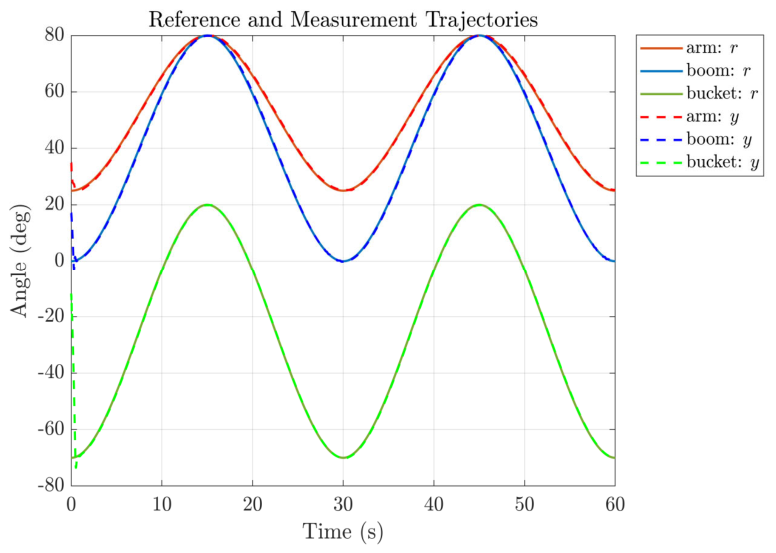
Figure 4 presents the trajectory tracking results of the three joints under the proposed ET-AGRP-C strategy. As illustrated, all joints effectively tracked the sinusoidal reference trajectory throughout the entire 60 s simulation cycle. Notably, the measured trajectories of the boom and the arm exhibited close agreement with the reference trajectories, with negligible deviation even within the wide angular range of ±80°. These findings validate the effectiveness and robustness of the asymmetric gain scheduling strategy for large-amplitude motion.
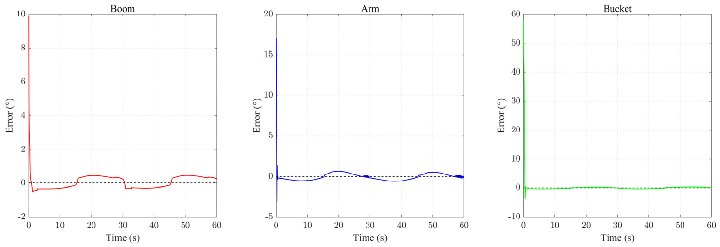
As shown in Figure 5, the time-domain error curves revealed a consistent convergence pattern across the three joints: initial error spikes arising from pose discrepancies underwent rapid attenuation and subsequently stabilized at near-zero levels. The bucket and arm exhibited relatively pronounced initial transient spikes, whereas the boom displayed comparatively subdued initial transients. In the steady-state regime, the tracking errors of all three joints remained tightly bounded; the bucket exhibited minimal residual fluctuations, while the boom showed slight deviations at isolated time instants. These observations demonstrated that the proposed strategy achieved effective suppression of tracking errors for each joint. The observed differences in initial deviations were predominantly attributable to disparate initial pose offsets from the reference trajectory among the joints, rather than to intrinsic differences in the underlying convergence mechanism.
Table 3 presents the full-cycle trajectory-tracking error statistics and computational-cost comparison for the three control strategies under 60 s simulations. For the boom joint, the RMSE values of standard PID and standard RBF-PID are 0.9676°and 1.0750°, respectively, whereas ET-AGRP reduces this metric to 0.8363°—corresponding to reductions of 13.6% and 22.2%; the overshoot decreased from 20.96–21.10% to 1.686%, representing the most pronounced improvement. For the bucket joint, the large initial deviation near −58°dominates the response, yielding comparable full-duration RMSE across the three controllers; however, after excluding the initial 1 s transient, the steady-state RMSE of ET-AGRP was merely 0.2419°, representing reductions of 14.4% and 44.1% relative to standard PID and standard RBF-PID, respectively, thereby corroborating its accuracy superiority in steady-state tracking. Regarding computational cost, standard RBF-PID demanded 135 FLOPs per cycle, approximately nine times that of standard PID; ET-AGRP constrained the weighted-average computational load to 18–19 FLOPs through event-triggered sparsification, representing only a 20–27% increase over standard PID while achieving an approximately 86% reduction relative to standard RBF-PID. The triggering proportions for all three joints remain below 1.5%, dropping to as low as 0.22% during steady-state phases, significantly alleviating the real-time computational burden on embedded platforms. In summary, ET-AGRP delivers tracking accuracy superior to standard RBF-PID while maintaining computational overhead comparable to standard PID, and reduces direction-switching overshoot by one order of magnitude.
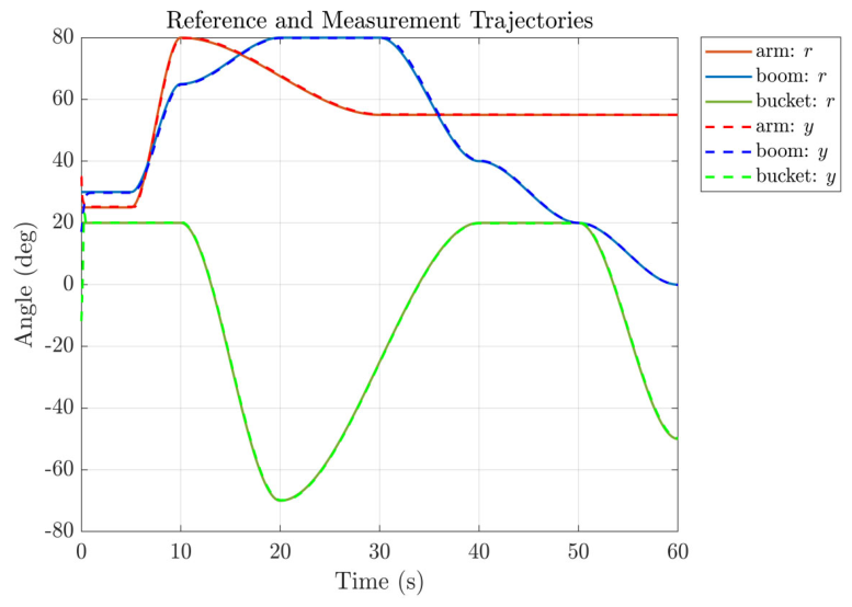
To validate the coordinated kinematic behavior of the three joints throughout the complete operational cycle, Figure 6 presents a comparative visualization of the reference and measured trajectories in joint space. Over the entire excavation cycle, the measured trajectories formed two closely coincident open curves that sequentially traversed five operational phases without exhibiting trajectory divergence or kinematic knotting. During the excavation penetration phase (10–30 s), the three joints maintained synchronism under large-range, highly dynamic variations, thereby attesting to the control strategy’s adaptability to strongly coupled operating conditions. During the loaded-bucket lifting and dump-positioning phase (30–50 s), the three joints cooperatively executed a smooth transition from the low-position excavation posture to the dumping posture. In the discharge-and-reset phase (50–60 s), the three joints underwent synchronous retraction, with the measured and reference trajectories converging concordantly toward the terminal point in joint space.
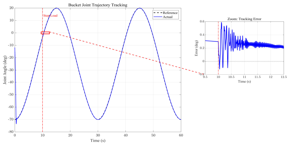
Figure 7 presents the tracking response of the bucket joint under a composite sinusoidal reference trajectory, together with a magnified view of the error dynamics in the vicinity of the step-load injection instant. The main plot indicates that the actual trajectory maintained close adherence to the reference counterpart throughout the 0–60 s interval, signifying favorable steady-state tracking performance under nominal operating conditions. Upon the injection of a 50 kN step disturbance at t = 10 s, the actual trajectory exhibited a transient excursion. The inset error magnification revealed that the tracking error remained quiescent at approximately 0.3° prior to the load application; at the instant of disturbance inception, the error underwent violent oscillation, attaining a positive peak approaching 0.6° and a negative trough of approximately −0.2°. Subsequently, the error exhibited an attenuating trend and progressively converged to a steady-state band near 0.2° after approximately t = 11 s. This result demonstrated that, although the step disturbance induced pronounced tracking deviation during the transient phase, the controller was capable of re-suppressing the error within a finite time, thereby manifesting robust recuperative capability against abrupt load perturbations.
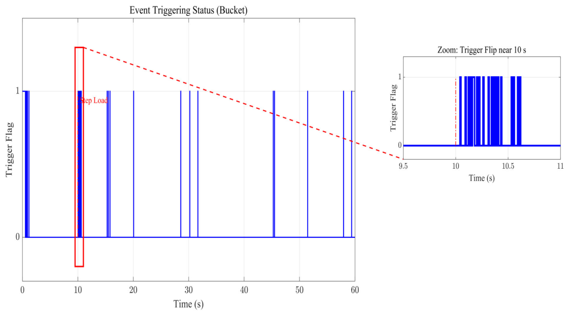
Figure 8 presents the event-triggering status over the corresponding interval, together with a magnified view in the vicinity of 10 s. The full-duration triggering profile revealed that the system resided predominantly in the non-triggered state during routine tracking, with the triggering condition satisfied only at sporadic time instants. This demonstrated that the event-triggered strategy effectively sparsified the computational and parameter-update frequency of the controller. In the magnified view, the triggering flag remained at 0 prior to the step-load injection a t = 10 s, indicating sparse-computation operation; upon disturbance occurrence, the flag immediately transitioned to 1, and a burst of dense triggering occurred within approximately 10–10.5 s before the flag rapidly reverted to 0. This phenomenon indicated that when the step disturbance drove the tracking error beyond the preset triggering threshold, the event-triggering condition was activated to enable online compensation of the unknown disturbance; once the error re-entered the threshold band, the system returned to the non-triggered state, thereby reconciling disturbance-rejection capability with computational resource conservation. By synthesizing Figure 7 and Figure 8, it was observed that immediately after disturbance injection, the triggering flag switched from 0 to 1 and maintained dense triggering throughout the period of severe error oscillation. As the error gradually converged, the triggering frequency diminished rapidly, and the system reverted to the non-triggered state. This result validated that when an abrupt disturbance caused the tracking error to exceed the preset threshold, the controller instantaneously exited the sparse mode, effectively eliminating the potential response blind zone inherent in pure event-triggered strategies during non-triggered intervals and ensuring disturbance-rejection capability under computationally constrained conditions.

4.3. Simulation Results Analysis of Asymmetric Control Strategy

To validate the efficacy of the proposed asymmetric control scheme and event-triggering mechanism, simulation studies were conducted in this section to investigate the bidirectional dynamic asymmetries inherent to the actuator joints of the hydraulic excavator. Independent extension–retraction cycle conditions were constructed for each joint, and the dynamic response differences of the boom, arm, and bucket joints during folding and unfolding were compared and analyzed, together with the computational load distribution and network weight convergence behavior under the event-triggered mechanism. These analyses comprehensively evaluated the adaptability of the asymmetric control architecture to heterogeneous bidirectional dynamics and the optimization effect on computational resources.
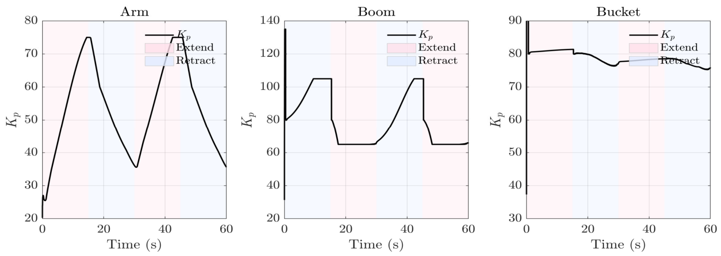
Figure 9 shows the asymmetric time-varying trajectory of the three-joint proportional gain Kp under the extend/retract conditions. The asymmetric scheduling verifies the actual execution of differential limiting in the code. The Kp curves of the three joints exhibited stepwise intermittent adjustment characteristics, confirming the sparse parameter update mode achieved through the synergistic interaction between the event-triggering mechanism and the RBF network. Furthermore, this validated the effectiveness of the rate-of-change limitation and conservative adjustment strategy, which effectively suppressed parameter overshoot induced by the coupling between the reduced chamber area and gravitational loading, thereby achieving a favorable balance between responsiveness and stability.
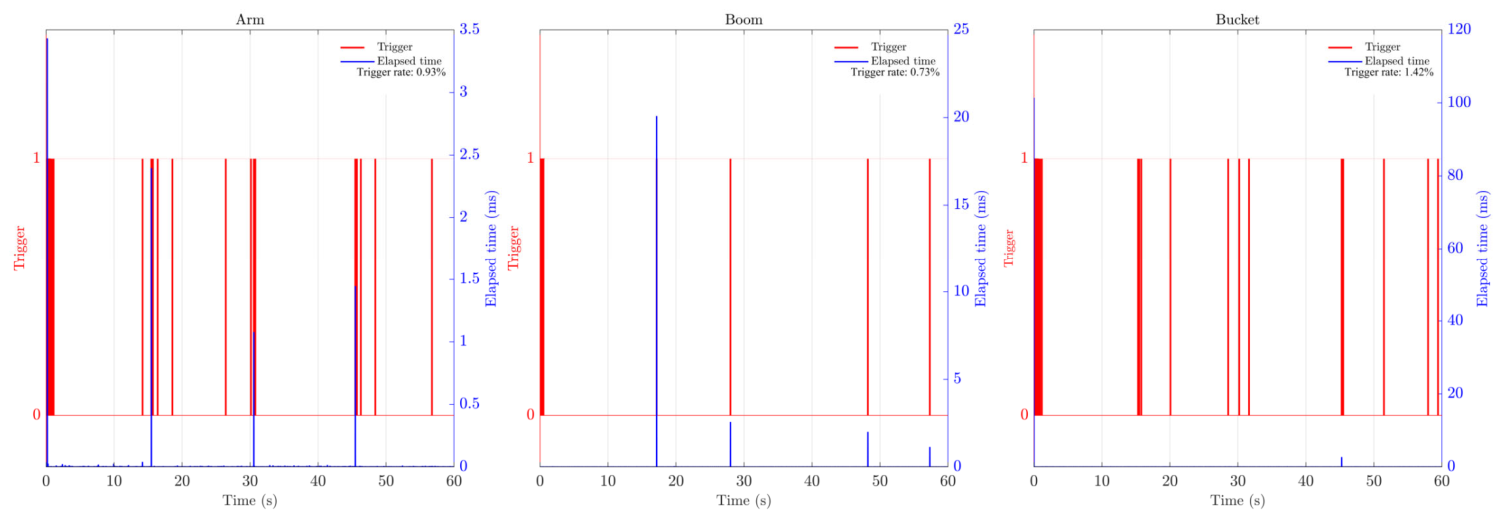
Based on the event-triggering and execution-latency profiles shown in Figure 10, the computational lightweightness and real-time applicability of the proposed strategy on embedded platforms are analyzed as follows. The simulation adopted a control cycle of 10 ms. The event-triggering rates of the three joints were 0.93%, 0.73%, and 4.23%, respectively, indicating that the RBF neural network remained dormant for over 95% of the control cycles, during which the controller merely executed underlying PID operations and asymmetric gain scheduling, thereby significantly reducing computational resource occupancy. The algorithmic latency during non-triggered cycles approached the lower bound of the MATLAB timing resolution and was therefore negligible. At triggering instants, the latency exhibited intermittent pulse characteristics, with peak values of approximately 3.5 ms for the boom joint, and sporadic high spikes reaching 25 ms and 45 ms for the arm and bucket joints, respectively; however, such extreme-latency events accounted for less than 0.1%. Weighted by the respective triggering rates, the average per-cycle latencies of the three joints were 0.03 ms, 0.02 ms, and 0.08 ms, all substantially below 1% of the control cycle. Compared with a conventional 15–20-node RBF-PID, which necessitates Gaussian kernel computation and weight updates in every cycle, the proposed six-node sparse architecture, coupled with the event-triggered mechanism, reduced the equivalent computational load. This, in principle, satisfied the real-time constraints of millisecond-scale embedded platforms, thereby validating the engineering implementability of the proposed strategy in resource-constrained environments.
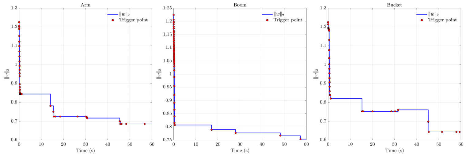
Figure 11 shows the time-varying convergence characteristics of RBF network weight w1 under the event-triggered mechanism. Unlike the continuous smooth convergence of the standard RBF, the curve exhibited pronounced stepwise intermittent updating characteristics, with the weight undergoing abrupt jumps at trigger instants indicated by red markers and maintaining constant-value plateaus between consecutive triggers. This pattern intuitively verified the sparsification effect of the differentiated threshold. The triggering density of the three joints showed significant variation. Owing to its pronounced inertial characteristics, the boom joint was configured with a relaxed threshold and rapidly entered a plateau phase lasting up to tens of seconds following the initial disturbance. The arm and bucket joints maintained intermediate-frequency updating. Prolonged plateau segments were observed for each joint, confirming the highly conservative strategy for RBF computation and weight updating during retraction strokes, which effectively suppressed the risk of parameter oscillation induced by the coupling between the reduced chamber area and gravitational loading. Finally, all weights converged to bounded steady-state values, thereby precluding parameter drift and indirectly corroborating the stability guarantee derived from the Lyapunov analysis.

5. Conclusions and Discussion

Conventional trajectory-tracking controllers for hydraulic excavators typically assume symmetric actuator dynamics and apply a uniform control law regardless of stroke direction, thereby neglecting the inherent bidirectional deviations arising from differential chamber areas and configuration-dependent gravitational coupling. To address the dynamic asymmetry induced by chamber area disparities and heterogeneous gravitational coupling during bidirectional motion of valve-controlled asymmetric hydraulic cylinders, this paper proposes an ET-AGRP control strategy for unmanned excavator autonomous operation. The strategy incorporates a hierarchical asymmetric gain-scheduling mechanism predicated on motion-direction identification to directly compensate for the bidirectional dynamic mismatch caused by the chamber area ratio and configuration-dependent gravitational coupling; distinct event-triggering configurations are established for extension and retraction strokes to achieve synergy between adaptive capability and computational lightweighting; and closed-loop uniform ultimate boundedness together with the existence of a positive lower bound on the event-triggering minimum inter-event interval are rigorously proven via a composite Lyapunov function. The following conclusions are drawn from MATLAB simulations:
(1)
By establishing a differentiated gain scheduling mechanism for extension and retraction strokes, the proposed approach addresses the overshoot and phase lag issues arising from differential chamber areas inherent to conventional symmetric control during stroke transitions. This enables synergistic configuration of the baseline PID control and RBF adaptive compensation within a direction-dependent parameter space. Simulation results demonstrate that this mechanism enables the arm and boom to maintain tight tracking across large angular motion ranges, with directional switching overshoot markedly reduced relative to standard PID. Although the bucket trajectory is dominated by substantial initial pose deviations, the steady-state RMSE diminishes to the order of 0.24° once the initial transient is excluded, thereby substantiating the compensatory efficacy of asymmetric scheduling in the steady-state regime.
(2)
An event-triggered sparse RBF mechanism based on differentiated thresholds is designed. By employing a six-node RBF network with optimized center-point coverage and a conservative update strategy during retraction phases, the mechanism preserves adaptive capability while substantially reducing computational load. The event-triggering rates for the three joints (boom, arm, and bucket) are only 0.93%, 0.73%, and 4.23%, respectively, indicating that the RBF network remains dormant for over 95% of the control cycles. The per-cycle FLOPs are reduced by approximately 86% compared with the standard RBF-PID, and the RMSE and MAE indices of ET-AGRP outperform those of the standard PID. This demonstrates that sparse computation and adaptive compensation can be synergistically optimized through judicious threshold design.
(3)
A composite Lyapunov function is constructed to rigorously establish the uniform ultimate boundedness of closed-loop tracking errors and parameter estimation errors, while guaranteeing the existence of a strictly positive lower bound on the event-triggering intervals. This addresses the system stability and parameter convergence issues inherent to event-triggered mechanisms. In simulations, the RBF weights exhibit staircase-like intermittent updates and ultimately converge to bounded steady-state values, which is qualitatively consistent with the theoretical expectation of bounded parameter estimation errors. Under step load injection, the system suppresses the error to within the steady-state band in approximately 1 s, verifying the disturbance-rejection capability during non-triggered phases.
Nevertheless, these conclusions remain predicated exclusively on a simplified hydraulic model and limited test conditions, without accounting for the spool mass, flow forces, and solenoid dynamics that induce phase lag and bandwidth limitations in actual proportional valves; the load-sensing characteristics of variable-displacement pumps and attendant 10–20% pressure fluctuations in multi-actuator parallel configurations; and the flow resistance contributed by long return pipelines, oil filters, and coolers. These omissions constitute the principal uncertainty boundary in migrating the current research to physical prototypes. While these idealizations facilitate the abstraction of secondary factors and the elucidation of the ET-AGRP compensation mechanism for bidirectional asymmetry during the theoretical stage, their cumulative effect implies that the reported accuracy metrics represent merely performance upper bounds under idealized conditions. Upon introduction of actual perturbations, the actuator velocity–pressure characteristics will exhibit nonlinear deviations, and the robustness of tracking accuracy requires further experimental validation.
Despite the aforementioned model limitations, the velocity-direction-identification-based differential gain scheduling mechanism of the ET-AGRP strategy exhibits cross-system universality in principle. The essence of this strategy lies in compensating for the dynamic asymmetry induced by differential effective areas of actuator chambers during bidirectional motion of valve-controlled actuators—a physical phenomenon not confined to excavator hydraulic manipulators. In the construction machinery domain, hydraulic crane telescopic booms, concrete pump truck distribution booms, and shield machine thrust cylinders widely employ valve-controlled asymmetric cylinders for bidirectional actuation. Their extension and retraction strokes similarly face flow-pressure gain mismatch arising from effective area discrepancies. The ET-AGRP direction-dependent gain scheduling framework can be directly embedded into the motion control layer of such systems, thereby enhancing trajectory tracking accuracy and operational smoothness under bidirectional load variations. Technology migration merely requires recalibrating the gain boundaries and RBF center coverage in accordance with the inertia matrix and supply pressure rating of the specific target system. In the aerospace and marine domains, aircraft and marine rudder hydraulic actuators exhibit asymmetric load characteristics during bidirectional deflection. Their uncertainty structure shares similarity with soil–machine interaction in excavators; migrating the proposed control strategy to such actuators could enhance the robustness of high-bandwidth electro-hydraulic servo systems against asymmetric disturbances. Nevertheless, these actuators impose substantially higher frequency-response requirements, necessitating recalibration of the event-triggering thresholds based on the sampling period and dynamic bandwidth, followed by hardware-in-the-loop validation. In vehicle active suspension systems, asymmetric actuator responses arising from valve-port area discrepancies similarly manifest during compression and rebound phases; consequently, the scheduling concept of ET-AGRP is theoretically extensible to such scenarios. The direction-identification-based gain scheduling in the proposed strategy provides a structured approach to compensating for asymmetric damping forces during compression and rebound strokes, which is expected to improve force-tracking consistency and thereby enhance ride comfort. Concurrently, the event-triggered sparse adaptive mechanism is anticipated to alleviate the computational burden on the onboard ECU, a consideration of critical importance for embedded control subject to stringent real-time constraints and limited power budgets. Nevertheless, active suspension systems exhibit markedly higher-frequency vibrational characteristics, significantly stronger stochasticity of road disturbances, and entirely distinct performance evaluation metrics. The direct migration of this strategy to such contexts currently remains a theoretical conjecture, and its feasibility necessitates in-depth investigation in future work.
In light of the aforementioned model inadequacies, subsequent research will be structured into two sequential phases. Phase I is dedicated to parametric sensitivity investigations at the simulation level: first-order valve lag dynamics, deterministic and stochastic supply pressure perturbations of ±5–10%, and non-zero return-line backpressure of 0.2–0.5 MPa will be systematically incorporated into the existing Simulink framework. This enables quantitative assessment of the governing laws through which individual and coupled disturbance factors influence tracking error RMSE and steady-state accuracy, thereby establishing a quantitative relationship between model fidelity and controller robustness. Phase II will advance toward the physical experimental platform, with the following primary objectives: (i) multi-actuator coordinated asymmetric control for full-scale excavators to address multi-joint coupling and hydraulic supply contention; (ii) integration of online parameter identification mechanisms to construct an adaptive ET-AGRP strategy, thereby enhancing adaptability to diverse machine configurations, hydraulic fluid temperatures, and soil conditions; (iii) hardware-in-the-loop testing and field experiments to provide reliable validation evidence for practical engineering deployment. The completion of these parametric sensitivity analyses and prototype validations will provide reliable benchmark data and parameter-tuning guidelines for the engineering migration of ET-AGRP to construction machinery, aerospace actuators, and other asymmetric drive systems.

Author Contributions

Conceptualization, T.W. and X.H.; methodology T.W. and X.H.; software, T.W.; validation, T.W., X.Z. and F.S.; formal analysis, X.Z. and Y.Z.; investigation, X.H. and Y.Z.; resources, X.H.; data curation, T.W., F.S. and X.H.; writing—original draft preparation, T.W. and X.H.; writing—review and editing, T.W., F.S., X.Z., Y.Z. and X.H.; visualization, T.W. and X.H.; supervision, X.Z. and F.S.; project administration, X.H. and F.S.; funding acquisition, X.H. and Y.Z. All authors have read and agreed to the published version of the manuscript.

Funding

This research was funded by Youth Independent Innovation Fund of Army Engineering University.

Data Availability Statement

The data that support the findings of this study are available from the corresponding authors upon reasonable request.

Acknowledgments

Thanks to all the authors for their participation and efforts in completing this manuscript.

Conflicts of Interest

The authors declare no conflicts of interest.

Nomenclature

A1Rodless cavity effective area
A2Rod cavity effective area
CdFlow coefficient
Ci, CeInternal/external leakage coefficients
FlExternal load force
KzAmplification factor/gain factor
nArea ratio
P1Rodless cavity pressure
P2Rod cavity pressure
λ 1 , λ 2 , λ 3 Coefficients of Lyapunov function terms
mtEquivalent mass of piston and load
PoEquivalent load pressure
PsOil supply pressure
Q1Rodless cavity flow rate (extension condition)
Q2Rod cavity flow rate (extension condition)
Q 1 Rodless cavity flow rate (retraction condition)
Q 2 Rod cavity flow rate (retraction condition)
qleakLeakage flow
ufInput voltage
v p h y Physical velocity limit
zState vecto
xvMain valve spool displacement
yHydraulic cylinder piston displacement
βeEffective bulk modulus of oil
γ(σ)Direction-dependent gain coefficient
ρOil density
σOperating mode identifier,
dmaxDisturbance upper bound
e(t)Tracking error
v max Upper bound of error change rate
d(t)Lumped disturbance,
h(x)Gaussian basis function vector
hminNon-zero lower bound of basis function vector
J(x)Input-output sensitivity
Kp, Ki, KdProportional/integral/derivative gains
K _ p , K ¯ p Lower and upper bounds of proportional gain
w . Weight estimation erro
κ i Upper bound of parameter change rate
Ω x Compact set of state space
T min Positive lower bound of triggering interval

References

  1. Li, Y.; Qi, X. Adaptive Funnel Control of Hydraulic Excavator Based on Neural Network. Machines 2025, 13, 1132. [Google Scholar] [CrossRef]
  2. Yang, J.; Gao, Y.; Guo, R.; Gao, Q.; Zhao, J. Research on excavator trajectory control based on hybrid interpolation. Sustainability 2023, 15, 6761. [Google Scholar] [CrossRef]
  3. Gong, J.; Chen, J.; Cai, D.; Wei, W.; Long, Y. Disturbance observer-based passivity and impedance control for trajectory tracking in autonomous hydraulic excavators. Autom. Constr. 2025, 170, 105898. [Google Scholar]
  4. Lee, D.; Jang, I.; Byun, J.; Seo, H.; Kim, H.J. Real-time motion planning of a hydraulic excavator using trajectory optimization and model predictive control. In Proceedings of the 2021 IEEE/RSJ International Conference on Intelligent Robots and Systems (IROS), Prague, Czech Republic, 27 September–1 October 2021. [Google Scholar]
  5. Hanafi Sheikhha, F.; Afzalaghaeinaeini, A.; Seo, J. Collaborative tracking control strategy for autonomous excavation of a hydraulic excavator. Eng. Proc. 2021, 10, 43. [Google Scholar] [CrossRef]
  6. Tao, X.; Liu, K.; Yang, J.; Chen, Y.; Chen, J.; Zhu, H. Sliding mode backstepping control of excavator bucket trajectory synovial in particle swarm optimization algorithm and neural network disturbance observer. Actuators 2025, 14, 9. [Google Scholar] [CrossRef]
  7. Muzayin, D.A.; Ataka, A.; Utomo, D.R. Vision-based MPC Trajectory Planning and Gain-Scheduled PID Control for Pick-and-Place Operation of an Autonomous Excavator. In Proceedings of the 2025 17th International Conference on Information Technology and Electrical Engineering (ICITEE), Bangkok, Thailand, 20–22 October 2025. [Google Scholar]
  8. Zhang, S.; Minav, T.; Pietola, M.; Kauranne, H.; Kajaste, J. The Effects of Control Methods on Energy Efficiency and Position Tracking of an Electro-Hydraulic Excavator Equipped with Zonal Hydraulics. Autom. Constr. 2019, 100, 129–144. [Google Scholar] [CrossRef]
  9. Wang, X. Fuzzy-PID Control in Electro-Hydraulic Proportional Valve System. In Proceedings of the 2010 IEEE 11th International Conference on Computer-Aided Industrial Design & Conceptual Design, Yiwu, China, 17–19 November 2010; IEEE: Piscataway, NJ, USA, 2010; Volume 2, pp. 1454–1457. [Google Scholar]
  10. Zhao, Y.; Zhou, Q.Y.; Shao, N.F.; Lu, R.R.; Hu, X.Z. Electro-hydraulic servo system based on RBF neural network fuzzy PID control. J. Mech. Electr. Eng. 2022, 39, 244–249. [Google Scholar]
  11. Yao, Z.; Zhao, S.; Tan, X.; Wei, W.; Wang, Y. Real-time task-oriented continuous digging trajectory planning for excavator arms. Autom. Constr. 2023, 154, 105043. [Google Scholar]
  12. Fan, R.; Li, Y.; Yang, L.; Qin, T.; Zhang, Y.; Wang, Z. Coordinated trajectory tracking control for mining excavator with oscillating external disturbance. J. Field Robot. 2024, 41, 352–368. [Google Scholar]
  13. Zou, Z.; Wang, C.; Hu, Y.; Liu, X.; Xu, B.; Xiong, R.; Fan, C.; Chen, Y.; Wang, Y. High-precision and high-efficiency trajectory tracking for excavators based on closed-loop dynamics. In Proceedings of the 2025 IEEE/RSJ International Conference on Intelligent Robots and Systems (IROS), Hangzhou, China, 19–25 October 2025; pp. 5617–5624. [Google Scholar]
  14. Feng, H.; Jiang, J.; Chang, X.; Yin, C.; Cao, D.; Yu, H.; Li, C.; Xie, J. Adaptive sliding mode controller based on fuzzy rules for a typical excavator electro-hydraulic position control system. Eng. Appl. Artif. Intell. 2023, 126, 107008. [Google Scholar] [CrossRef]
  15. Zhou, S.; Liu, Z.; Li, M.; Liu, D.; Wang, C.; Li, H. A Study on Fractional-Order Adaptive Super-Twisting Sliding Mode Control for an Excavator Working Device. Appl. Sci. 2025, 15, 12581. [Google Scholar]
  16. Bender, F.A.; Göltz, S.; Bräunl, T.; Sawodny, O. Modeling and offset-free model predictive control of a hydraulic mini excavator. IEEE Trans. Autom. Sci. Eng. 2017, 14, 1682–1694. [Google Scholar] [CrossRef]
  17. Molaei, A.; Heravi, M.; Ghabcheloo, R. Learning to Capture Rocks using an Excavator: A Reinforcement Learning Approach with Guiding Reward Formulation. arXiv 2025, arXiv:2510.04168. [Google Scholar]
  18. Karam, Z.A.; Hassan, M.Y.; Humaidi, A.J. Intelligent Leader–Follower Formation Control Using an Interval Type-2 Fuzzy Logic Controller and Adaptive Radial Basis Function Neural Networks. J. Intell. Fuzzy Syst. 2025, 18758967251409366. [Google Scholar] [CrossRef]
  19. Humaidi, A.J.; Hashim, A.A.; Al-Shuwaili, A.; Kadhim, S.K. Particle swarm optimization of adaptive backstepping sliding mode control for a PAM-actuated hanging mass. Int. Rev. Appl. Sci. Eng. 2025, 16, 345–360. [Google Scholar]
  20. Hasan, A.F.; Raheem, F.A.; Humaidi, A.J. Improving Pressure Control in Artificial Ventilation Systems Using a Neural Network-Based Adaptive PID Controller. Automation 2026, 7, 37. [Google Scholar] [CrossRef]
  21. Wang, H.; Xu, M.; Cao, Z. Analysis of underlapped symmetrically ported valve-controlled asymmetric cylinder drive. Appl. Sci. 2024, 14, 2870. [Google Scholar] [CrossRef]
  22. Xu, W.; Zeng, L. Invariance compensation PID control for a proportional valve-controlled asymmetric cylinder system. Adv. Mech. Eng. 2025, 17. [Google Scholar] [CrossRef]
  23. Chen, J.; Fei, Z.; Lyu, L.; Xia, W.; Sun, X.-M. Adaptive robust motion control for hydraulic actuators with an adjustable event trigger. IEEE Trans. Syst. Man Cybern. Syst. 2025, 55, 1846–1858. [Google Scholar] [CrossRef]
  24. Semwal, V.B.; Gupta, Y. Determining homogenous transformation matrix from DH parameter table using deep learning techniques. Res. Rep. Comput. Sci. 2023, 2, 23–34. [Google Scholar] [CrossRef]
  25. Jia, L.; Liu, S.; Cao, C.; Kang, Y.; Zhu, Y.; Wang, L.; Xu, D.; Cheng, R. Kinematics and spatial structure analysis of TBM gunite robot based on D–H parameter method. Sci. Rep. 2024, 14, 13649. [Google Scholar] [CrossRef] [PubMed]
  26. Lu, Z.; Lin, S.; Chen, J.; Gu, T.; Xie, Y. A multi-objective collaborative optimization method for the excavator working device to support energy consumption reduction. Energies 2023, 16, 7056. [Google Scholar] [CrossRef]
  27. Li, S.; Zhou, G.; Wang, S.; Jia, X.; Hou, L. Multi-sensor data fusion and deep learning-based prediction of excavator bucket fill rates. Autom. Constr. 2025, 171, 106008. [Google Scholar]
  28. Ding, H.; Sang, Z.; Li, Z.; Shi, J.; Wang, Y.; Meng, D. Trajectory planning and control of large unmanned excavators based on inclination-displacement mapping. Autom. Constr. 2024, 158, 105209. [Google Scholar]
  29. Jin, Z.; Gong, M.; Zhao, D.; Zhang, Y.; Liu, W.; Zhu, J.; Su, B. MPC motion control of boom descending of unmanned excavator based on regenerative valve. Heliyon 2024, 10, e29915. [Google Scholar] [CrossRef] [PubMed]
  30. Feng, H.; Zhong, Y.; Zhou, C.; Ji, S.; Yin, C.; Cao, D. Collaborative high-precision trajectory control for heavy excavators based on an improved particle swarm optimization algorithm. Autom. Constr. 2025, 180, 106546. [Google Scholar] [CrossRef]
  31. Xu, C.; Xu, X.; Liu, Z.; Wang, X. Research on multi-cylinder synchronous control system of multi-directional forging hydraulic press. J. Phys. Conf. Ser. 2022, 2338, 012081. [Google Scholar]
  32. Li, W.; Han, H.Y.; Liu, C. Analysis on hydraulic dynamic stiffness characteristics and experimental research of asymmetric valve-controlled asymmetric cylinder system. Sci. Rep. 2026, 16, 3601. [Google Scholar] [CrossRef]
  33. Xia, Y.; Qi, M.; Lyu, L.; Jin, Z.; Zhang, L.; Chen, Z.; Yao, B. Advanced motion control of hydraulic manipulator with precise compensation of dynamic friction. IEEE Trans. Ind. Inform. 2024, 20, 9375–9384. [Google Scholar] [CrossRef]
  34. Wang, M.; Li, L.; Wang, A.; Ren, H.; Gao, Y. Multiple quadrants displacement tracking control of independent metering electro-hydraulic system. Sci. Rep. 2024, 14, 21951. [Google Scholar] [CrossRef]
  35. Li, B.; Li, L.; Ge, G. Response of an Oscillator with Shape Memory Alloy Element Under Gaussian White Noise and Colored Noise Excitation Based on Radial Basis Function Neural Network. J. Nonlinear Math. Phys. 2025, 32, 57. [Google Scholar] [CrossRef]
  36. Wu, M.; Yan, C.; Xia, J. Adaptive Fuzzy Event-Triggered Tracking Control of Flexible-Joint Robot Systems: Design and Experiment. Int. J. Fuzzy Syst. 2025, 27, 1625–1635. [Google Scholar]
  37. Yang, Y.; Zhang, L. Event-triggered adaptive tracking control of a class of nonlinear systems with asymmetric time-varying output constraints. Front. Inf. Technol. Electron. Eng. 2024, 25, 1134–1144. [Google Scholar]
  38. Vallarella, A.J.; Cardone, P.; Haimovich, H. Semiglobal exponential input-to-state stability of sampled-data systems based on approximate discrete-time models. Automatica 2021, 131, 109742. [Google Scholar] [CrossRef]
  39. Huff, D.D.; Fiacchini, M.; Da Silva, J.M.G. Stability and stabilization of aperiodic sampled-data systems subject to control input saturation: A set invariant approach. IEEE Trans. Autom. Control 2021, 67, 1423–1429. [Google Scholar] [CrossRef]
  40. Lanza, L.; Dennstädt, D.; Worthmann, K.; Schmitz, P.; Şen, G.D.; Trenn, S.; Schaller, M. Sampled-data funnel control and its use for safe continual learning. Syst. Control Lett. 2024, 192, 105892. [Google Scholar] [CrossRef]
  41. Wei, Y.; Hao, M.; Yu, X.; Ou, L. Asymmetric time-varying integral barrier Lyapunov function based adaptive optimal control for nonlinear systems with dynamic state constraints. Front. Inf. Technol. Electron. Eng. 2024, 25, 887–902. [Google Scholar] [CrossRef]
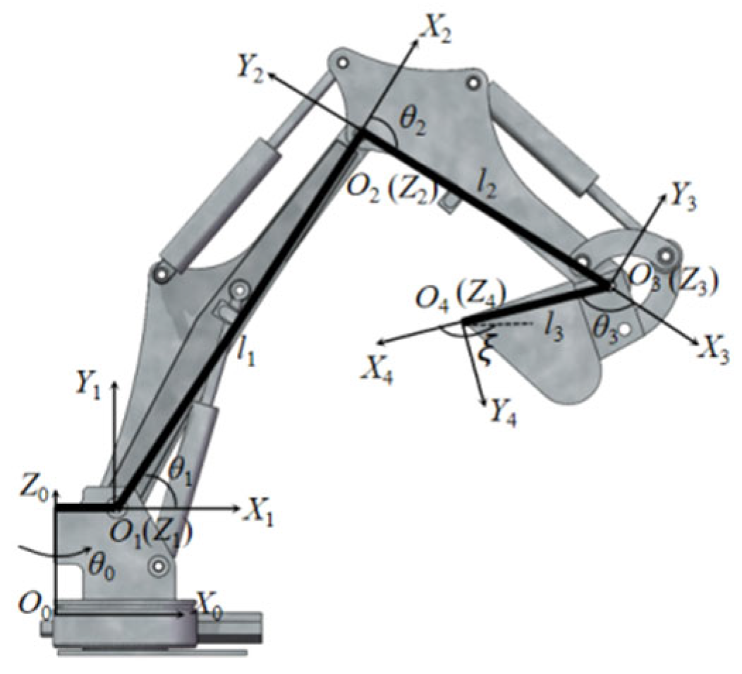
Figure 1. D-H coordinate system of unmanned excavator.
Processes 14 02163 g001
Figure 2. Structure diagram of valve-controlled hydraulic cylinder system.
Processes 14 02163 g002
Figure 3. Controller block diagram.
Processes 14 02163 g003
Figure 4. Three-joint trajectory tracking curve.
Processes 14 02163 g004
Figure 5. Error time domain curve.
Processes 14 02163 g005
Figure 6. Three-joint trajectory tracking profiles during excavation operations.
Processes 14 02163 g006
Figure 7. Trajectory Tracking Curves Under Step-Load Disturbance.
Processes 14 02163 g007
Figure 8. Event-triggered state under step-load disturbance.
Processes 14 02163 g008
Figure 9. Three-joint proportional gain.
Processes 14 02163 g009
Figure 10. Triggering and time-consuming characteristics.
Processes 14 02163 g010
Figure 11. RBF network weight.
Processes 14 02163 g011
Table 1. D-H Parameters of the Working Mechanism.
Joint i θ i a i d i α i
1 θ 1 a 0 d 0 π 2
2 θ 2 L 1 00
3 θ 3 L 2 00
4 θ 4 L 3 00
Table 2. Positivity Analysis of λ.
Operating ConditionJointKp γ 1 γ 2 γ 3 λ 1 λ 2 λ 3
extensionBoom65.01.01.01.063.980.175014.90
Arm15.01.01.01.013.340.01438.83
Bucket35.01.01.01.033.750.083319.59
retractionBoom20.01.01.01.018.000.175014.90
Arm12.01.01.01.010.440.01438.83
Bucket25.01.01.01.023.440.083319.59
Table 3. Trajectory tracking error statistics.
JointActuatorRMSEMAEMaxAEMaxOvFLOPs
ArmPID0.58550.41639.945016.713715
ArmRBF-PID0.54170.29409.969517.1425135
ArmET-AGRP0.49370.35699.87490.99618
BoomPID0.96760.578217.293520.957715
BoomRBF-PID1.07500.490817.397121.1048135
BoomET-AGRP0.83630.397417.0791.68618
BucketPID3.45233.45230.54550.739915
BucketRBF-PID3.30403.30400.59251.4205135
BucketET-AGRP3.27923.27920.48240.62319
BucketET-AGRP
SS (t > 1 s)
0.24190.22210.44030.26419
Disclaimer/Publisher’s Note: The statements, opinions and data contained in all publications are solely those of the individual author(s) and contributor(s) and not of MDPI and/or the editor(s). MDPI and/or the editor(s) disclaim responsibility for any injury to people or property resulting from any ideas, methods, instructions or products referred to in the content.