Article

Particle Size Distribution Characteristics of Drilled Cuttings During Horizontal Section Drilling in Coal-Rock Gas Wells


1
State Key Laboratory of Petroleum Resources and Engineering, China University of Petroleum (Beijing), Beijing 102249, China
2
CNPC Engineering Technology R&D Company Limited, Beijing 102206, China
3
Postdoctoral Workstation, CNPC Bohai Drilling Engineering Company Limited, Tianjin 300457, China
*
Author to whom correspondence should be addressed.
Processes 2026, 14(13), 2049; https://doi.org/10.3390/pr14132049
Submission received: 24 May 2026 / Revised: 15 June 2026 / Accepted: 23 June 2026 / Published: 24 June 2026
(This article belongs to the Section Petroleum and Low-Carbon Energy Process Engineering)

Abstract

During horizontal drilling in coal-rock gas reservoirs, the particle size distribution (PSD) of drilled cuttings directly affects drilling efficiency, hole cleaning, and wellbore stability. However, the evolution of cuttings PSD and its controlling mechanisms during coal-rock fragmentation remain insufficiently understood. In this study, a drill bit–coal-rock interaction model was established using the discrete element method (DEM) and calibrated against uniaxial compression experiments. The effects of weight on bit (WOB), rotational speed, and depth of cut (DOC) on cuttings PSD were quantitatively investigated. The results show that the relative influence on the maximum cutting size followed the order of DOC > WOB > rotational speed, whereas the influence on the average cutting size followed the order of rotational speed > WOB > DOC. Increasing DOC from 0.5 mm to 1.5 mm increased the maximum cutting size from 11.6 mm to 29.4 mm. Increasing WOB promoted the generation of medium- and large-sized cuttings, thereby increasing hole-cleaning requirements. Meanwhile, increasing rotational speed from 40 rpm to 90 rpm reduced the average cutting size and shifted the dominant cutting fraction from 4–6 mm to 1–4 mm. DEM observations reveal that cutting PSD evolution is jointly controlled by primary brittle fracture and secondary particle breakage through a five-stage fragmentation process involving stress concentration, microcrack initiation, crack propagation and coalescence, fragment detachment, and secondary fragmentation. Field validation using 146 cutting samples demonstrated the applicability of the proposed optimization strategy. Under the investigated drilling conditions, a DOC of approximately 0.5 mm and a rotational speed of 70–90 rpm were found to effectively limit oversized cutting generation. These findings improve the mechanistic understanding of cutting PSD evolution and provide practical guidance for drilling parameter optimization and hole-cleaning management in coal-rock gas horizontal wells.

1. Introduction

Coal-rock gas is a critical unconventional natural gas resource, and its efficient development largely relies on an integrated strategy of horizontal drilling combined with volume fracturing. In field practice, the horizontal sections of coal-rock gas wells are predominantly drilled using polycrystalline diamond compact (PDC) bits driven by a downhole motor assembly [1,2]. However, coal-rock formations are typically characterized by well-developed cleats and microfractures, strong structural heterogeneity, and highly complex mechanical behavior. These intrinsic properties lead to the generation of drilled cuttings with irregular morphologies and highly dispersed particle size distributions during drilling. Furthermore, the tendency of coarse particles to accumulate and agglomerate further exacerbates hole cleaning inefficiency and reduces cutting transport capacity. This induces severe drilling complications such as pipe sticking and wellbore collapse, ultimately constraining both drilling efficiency and wellbore quality [3,4].
Within this context, the particle size distribution of drilled cuttings serves as a direct indicator of coal-rock breaking intensity, and its evolution is governed by the coupled interaction of multiple drilling parameters, including WOB, RPM, and DOC. Improper parameter configurations may generate excessively coarse cuttings, increasing the risk of poor hole cleaning, stuck pipe, and wellbore instability, whereas overly fine cuttings may reflect inefficient energy utilization and reduced rate of penetration (ROP). Accordingly, elucidating the evolution of cutting size under varying drilling conditions is essential for optimizing drilling parameter design, enhancing rock-breaking efficiency, and ensuring wellbore stability [5,6].
From a methodological perspective, DEM has been widely recognized as an effective numerical framework for simulating the mechanical response of discontinuous media under large deformation and nonlinear failure conditions [7]. Specifically, particle flow code (PFC) represents rock as an assembly of bonded rigid particles interacting through contact mechanics, enabling the explicit reproduction of fracture initiation and propagation processes [8,9,10]. Previous studies have demonstrated that cutter shape significantly affects coal-rock breaking behavior, and optimized PDC cutter designs have been proposed for soft coal formations based on PFC simulations [11]. In addition, the synergistic effects of WOB and RPM on rock-breaking efficiency under different lithological conditions have been clarified, while fractal-based approaches have been introduced to characterize rock breaking and cutting size distribution [12,13]. Nevertheless, existing studies are still largely limited to single-parameter or simplified coupling analyses, and systematic investigations into cutting size evolution under multi-parameter interactions during horizontal drilling remain insufficient to capture complex field conditions involving the dynamic adjustment of multiple drilling parameters [14,15].
To address these limitations, this study develops a DEM-based PFC numerical model for coal-rock gas formations in a selected block of the eastern Ordos Basin to simulate the rock-breaking process during horizontal drilling. The influences of WOB, RPM, and DOC on coal-rock breaking behavior and the resulting drilled cutting particle size distribution are systematically investigated. Furthermore, field cutting samples collected under different drilling parameter conditions are analyzed and compared with numerical results. This comparison validates the model and reveals the evolution characteristics of cutting size distribution in coal-rock gas horizontal wells. The findings provide theoretical support for bit selection, drilling parameter optimization, and hole-cleaning control, and are expected to contribute to improved drilling efficiency, reduced downhole risks, and lower overall drilling costs.
Despite these contributions, it is necessary to acknowledge the limitations of the present study. First, the current DEM framework focuses primarily on the mechanical fragmentation process of the coal-rock mass, thereby simplifying the complex fluid–solid coupling effects induced by drilling mud circulation. Second, the simulations do not fully account for the extreme downhole temperature variations, which may influence the geomechanical properties of the coal formations. Therefore, while the current model reliably captures the geometric evolution of drilled cuttings under multi-parameter interactions, future research should integrate thermo-hydro-mechanical (THM) coupling to further bridge the gap between numerical simulations and actual downhole environments.

2. Geological Setting and Reservoir Characteristics

2.1. Geological Background and Drilling Characteristics

The study area is located in the northeastern Yishan Slope of the Ordos Basin, where the regional structure is relatively gentle and characterized by a west-dipping monocline with limited fault development, providing favorable geological conditions for coal-rock gas accumulation. The coal-bearing strata are generally buried at depths greater than 3000 m. The horizontal section of Well W1 is located at depths ranging from 3185 to 4685 m, representing a typical deep coal-rock gas reservoir. The reservoir exhibits a dual-porosity system dominated by micropores and cleat fractures, accompanied by high in situ stress and ultra-low permeability (averaging approximately 0.054 mD). These characteristics classify the reservoir as a typical deep, overpressured, and low-permeability unconventional gas system.
The well was drilled using a three-string casing program. During drilling in the deep coal-rock formations, the combined effects of highly developed fractures, poor wellbore stability, and inefficient cutting transport frequently promote cutting bed accumulation in the horizontal section, thereby increasing operational risks during tripping and casing running [16,17]. To mitigate these challenges, well trajectory design was optimized based on inclination survey data and natural formation deflection tendencies to improve wellbore smoothness. Additionally, the inclination control capacity of BHA was optimized to reduce sliding drilling and increase the proportion of compound drilling, thereby improving directional drilling efficiency. A nano-plugging composite organic salt drilling fluid system with a density ranging from 1.30 to 1.45 g/cm3 was employed to achieve low fluid loss, strong lubrication, and drag reduction while simultaneously balancing wellbore stabilization and lost circulation control requirements. In addition, drilling, circulation, and tripping parameters were optimized to improve rock-breaking efficiency and hole-cleaning performance and to reduce casing running friction [18,19].

2.2. Coal-Rock Characteristics and Mechanical Properties

The coal-rock reservoirs in the study area exhibit a spatial distribution pattern characterized by greater thickness in the central zone and thinner intervals toward the margins. Reservoir pore structures are dominated by micropores, which account for approximately 73.31% of the total pore volume. In contrast, macropores mainly serve as gas migration pathways, indicating a typical low-porosity and low-permeability reservoir system. The fracture network is primarily composed of endogenous tensile fractures, and the reservoirs exhibit relatively high gas saturation, providing favorable conditions for gas accumulation and production.
The deep coal-rock formations, buried at depths ranging from 3000 to 4700 m, are subjected to high in situ stress conditions dominated by a normal-faulting stress regime. The coal-rock exhibits moderate mechanical strength overall, with significantly higher compressive strength in the dry state than in a water-saturated state. A relatively low softening coefficient indicates pronounced mechanical weakening upon water exposure. Mechanical parameters, including tensile strength and cohesion, are strongly influenced by coal structure and gangue distribution. In addition, negative structural zones generally exhibit higher in situ stress levels than positive structural zones due to greater overburden loading and tectonic stress concentration.

3. Numerical Modeling of Coal-Rock Breaking

3.1. Modeling Methodology

Rock fragmentation during drill-bit cutting involves crack initiation, crack propagation, crack coalescence, and subsequent fragment detachment, leading to the formation of discrete drilled cuttings. Crack evolution is generally treated as a continuous damage process, whereas fragment separation and interaction are inherently discontinuous. Therefore, a numerical framework capable of representing both fracture evolution and discrete particle behavior is required.
Compared with continuum-based approaches such as the finite element method (FEM), the discrete element method (DEM) offers distinct advantages for simulating drilling-induced fragmentation. FEM is highly effective for analyzing stress distribution, deformation, and failure initiation in continuous media; however, the simulation of large-scale fracture propagation, fragment separation, and cutting generation often requires predefined crack paths, element deletion techniques, or repeated remeshing procedures. In contrast, DEM explicitly represents rock as an assembly of bonded particles and naturally reproduces crack initiation, propagation, coalescence, fragment detachment, and particle interaction through progressive bond breakage. More importantly, DEM enables direct tracking and quantitative characterization of generated fragments, including their number, size distribution, and morphology, which constitute the primary objectives of this study. Therefore, DEM-PFC was used for the numerical simulation of coal-rock fragmentation and drilled cuttings generation.
In DEM, rock is modeled as an assembly of rigid particles interacting through contact and bonding models, enabling simulation of force transmission, deformation, and fracture under external loading [20]. Particle motion satisfies Newton’s second law and rotational equilibrium, while inter-particle forces are updated through force–displacement laws. These interactions include normal and tangential elastic forces, damping, and bond failure criteria governing cohesion and fracture. Common contact formulations include the linear contact model and the linear parallel bond model.
In PFC simulations, the contact and bonding models jointly define the macroscopic response of granular assemblies and form the core constitutive framework for cemented geomaterials such as coal rock [21]. The contact model governs frictional sliding, elastic response, and energy dissipation. Normal and tangential stiffness control contact elasticity, while the friction coefficient determines shear resistance and influences macroscopic behavior such as shear strength and repose angle. In drilling simulations, the contact model primarily describes cutting transport, collision, and accumulation within the annulus.
The bonding model provides cohesion, tensile resistance, and stiffness to the particle assembly, enabling the representation of intact rock failure behavior. Bond stiffness and bond strength in both normal and tangential directions determine the load-bearing capacity of bonded contacts, while the bond radius multiplier controls the effective bonding range and influences the macroscopic brittleness of the material. Therefore, the bonding model is the primary representation of intact coal-rock strength and integrity.
During PFC simulations, the bonding and contact models operate cooperatively. Bonded particles initially behave as a continuous solid medium; once the local stress exceeds the bond strength, bond breakage occurs, and the interaction transitions to a pure contact model, which subsequently governs sliding, collision, and separation along newly generated fracture surfaces. This mechanism enables a realistic simulation of the progressive transition from intact coal rock to fragmented cuttings under drilling action [22].
Accurate calibration of microscopic parameters associated with both contact and bonding models is essential for reproducing realistic macroscopic mechanical behavior of coal-rock materials [23]. Together, these models establish the physical basis for simulating the entire process from drill-bit rock-breaking to drilled cutting generation and transport, thereby bridging geological characteristics and computational modeling. Compared with conventional continuum-based approaches, DEM-PFC not only captures the progressive evolution of fracture networks and fragment separation but also provides direct quantitative information on cutting size distribution and morphology. These capabilities make DEM-PFC particularly suitable for investigating the mechanisms governing drilled cutting generation and particle size evolution in coal-rock drilling.

3.2. Numerical Modeling of Uniaxial Compression

Uniaxial compression tests were performed on three coal-rock specimens and three coal-gangue rock specimens in this study. The resulting mechanical parameters are summarized in Table 1. Table 1 shows that coal-rock formations in the study area exhibit significant heterogeneity in mechanical properties. Coal density ranges from 1.32 to 1.35 g/cm3, with uniaxial compressive strength (UCS) varying between 7.9 and 13.2 MPa. In contrast, gangue density ranges from 1.93 to 2.12 g/cm3, with UCS values of 21.3–24.3 MPa. The horizontal section of W1 (3185–4685 m, approximately 1500 m long) is located within these coal-rock intervals. These measured mechanical parameters provide the experimental basis for subsequent numerical modeling and parameter calibration.
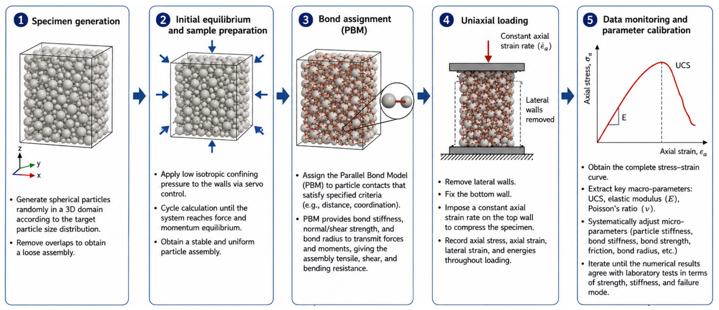
In PFC simulations, numerical modeling of uniaxial compression tests represents a critical prerequisite for calibrating microscopic mechanical parameters and constructing mechanically equivalent coal-rock specimens. The objective is to iteratively adjust particle-scale parameters through virtual experiments until the simulated macroscopic mechanical responses, including stress–strain behavior and failure patterns, closely match laboratory measurements.
The microscopic parameters were determined through an iterative calibration procedure. Numerical uniaxial compression simulations were repeatedly performed while systematically adjusting particle stiffness, bond stiffness, bond strength, and friction parameters. The calibration targets included the elastic modulus, peak strength, stress–strain response, and failure characteristics measured in the laboratory tests. The calibration process was considered converged when further adjustments of microscopic parameters resulted in less than a 5% variation in the simulated elastic modulus and peak strength, and when the overall stress–strain response and failure pattern remained stable. The final parameter set was subsequently adopted for the drill-bit cutting simulations.
The detailed DEM-PFC modeling workflow for the uniaxial compression tests is shown in Figure 1.
The establishment of the coal-rock uniaxial compression model provides a reliable foundation for subsequent investigations of dynamic processes such as drill-bit cutting and drilled cutting generation. Through iterative calibration, a mechanically equivalent “numerical coal-rock” specimen was successfully developed, with microscopic parameter sets that are highly consistent with the macroscopic mechanical properties of the target formations.
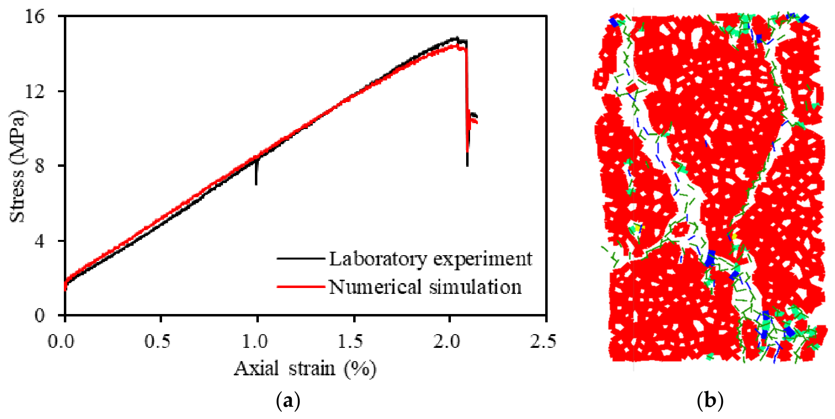
As shown in Figure 2, the numerical stress–strain curves exhibit close agreement with the laboratory measurements. It should be noted that this high consistency is primarily attributed to the DEM–PFC calibration procedure rather than an independent prediction. Prior to the drilling simulations, the microscopic contact and bond parameters were systematically calibrated using the experimentally measured macroscopic mechanical properties of the coal-rock specimens, including the elastic modulus, peak strength, post-peak response, and failure characteristics. Through iterative numerical testing and parameter adjustment, the simulated stress–strain response gradually converged toward the laboratory results. Therefore, the high degree of similarity between the numerical and experimental curves shown in Figure 2 reflects the effectiveness of the calibration process and confirms that the calibrated numerical specimens can reliably reproduce the mechanical behavior of the target coal-rock formations.
The establishment of such mechanically equivalent numerical specimens provides a physically representative basis for subsequent simulations of cutter–rock interaction and drilled cutting generation. By introducing appropriate bond-strength distributions and material heterogeneity, the calibrated model reproduces the dominant brittle splitting failure characteristics observed in laboratory experiments rather than homogeneous plastic deformation. These results demonstrate that the model captures the essential mechanical behavior of the target coal-rock formations, thereby providing confidence in its application to investigate cuttings generation mechanisms and the relative influence of drilling parameters.

3.3. Numerical Modeling of Coal-Rock Cutting by Drill Bit

Based on the calibrated coal-rock mesoscopic parameters obtained from the uniaxial compression experiments and subsequent DEM-PFC simulations, a numerical drilling model was developed to simulate the dynamic coal-rock cutting process induced by the drill bit. This model aims to reproduce the rock fragmentation behavior during drilling and quantitatively characterize the evolution of the drilled cutting PSD. Consequently, the drilling model serves as a critical link between the static mechanical properties of the coal-rock and the dynamic drilling response.
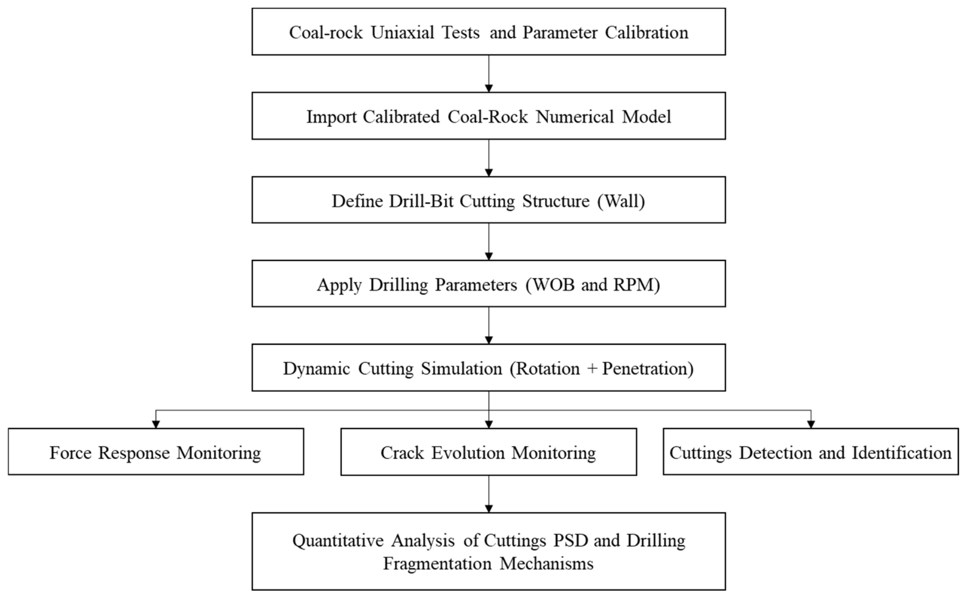
After validating the reliability of the calibrated numerical coal-rock model, a two-dimensional coal-rock specimen with dimensions of 30 mm × 10 mm was constructed in PFC. Different drilling operating conditions, including WOB and RPM, were applied to investigate their influences on coal-rock fragmentation characteristics and the evolution of the cutting PSD. The modeling procedure mainly consisted of four stages: coal-rock model importation, drill-bit definition, dynamic loading, and process monitoring, as illustrated in Figure 3.
First, the calibrated coal-rock numerical specimen was imported as the cutting target. Its mesoscopic parameters, including bond strength and particle stiffness, were inherited directly from the validated uniaxial compression model. This ensured that the macroscopic mechanical behaviors, such as brittleness and strength, were accurately reproduced. Second, the drill-bit cutting structure was simplified using combined wall elements in PFC. The geometric shape and spatial position of the PDC cutter were precisely defined to represent the actual cutting configuration during drilling. Third, drilling parameters were converted into dynamic boundary conditions. The WOB was applied through a servo-control mechanism in the form of a constant normal force, while the RPM was transformed into the tangential rotational velocity of the cutter. The drill bit simultaneously performed rotational and axial feeding motions to simulate the coupled cutting trajectory within the coal-rock medium.
Finally, the entire cutting process was continuously monitored and recorded. Throughout the simulation, mechanical responses, including cutting force and drilling velocity, were collected throughout the simulation. Meanwhile, the initiation and propagation of microcracks were characterized by tracking the breakage of parallel bonds between particles. In addition, a customized identification algorithm was developed to automatically recognize detached particle clusters based on particle displacement, velocity, and bonding states. This enabled the real-time identification and statistical analysis of drilled cuttings.
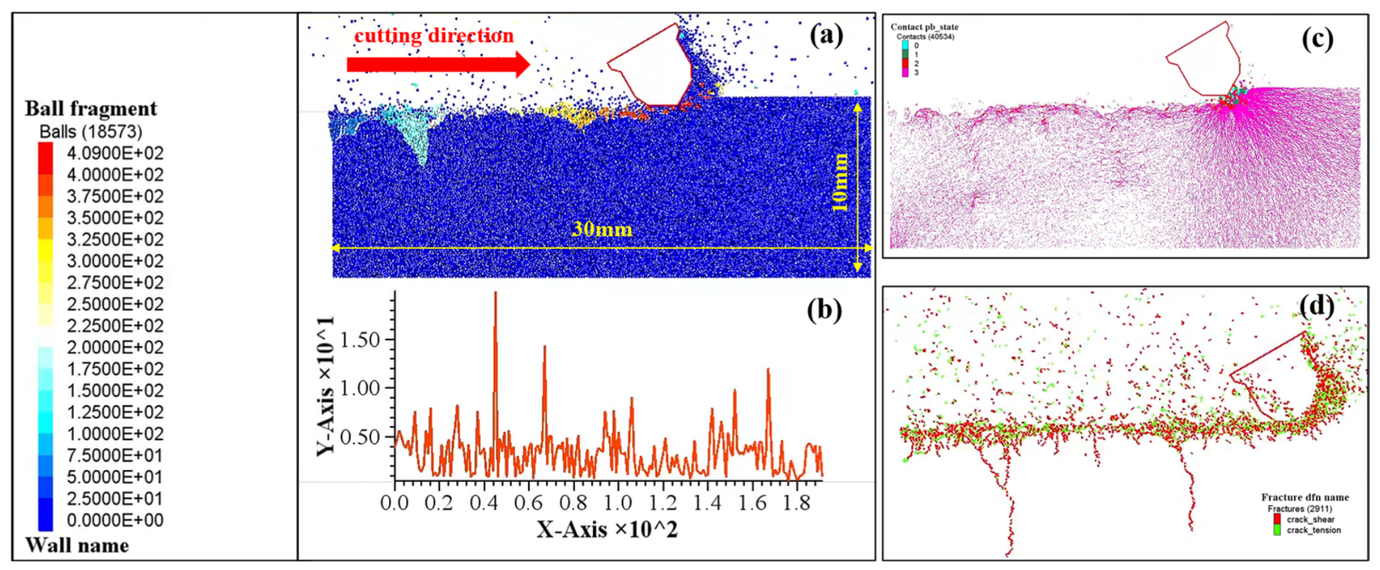
As shown in Figure 4, the proposed numerical model enables the visualization of the complete coal-rock fragmentation process, including crack initiation, crack propagation, and cutting detachment. More importantly, it quantitatively outputs both process parameters (e.g., cutting force) and outcome parameters (e.g., cuttings number, equivalent particle size distribution, and morphological characteristics). By systematically varying drilling parameters, deterministic relationships among drilling operational parameters, mesoscopic fragmentation mechanisms, and macroscopic cutting characteristics can be established. This provides a mechanistic basis for drilling parameter optimization in coal-rock gas reservoirs.

3.4. DOC as an Engineering Indicator: Calculation and Field Control

In conventional drilling practice, DOC is often regarded as a derived parameter resulting from the combined effects of WOB, RPM, bit geometry, and formation properties. However, from the perspective of rock-breaking mechanics, DOC represents the actual penetration achieved by individual cutters and directly reflects the intensity of the cutter–rock interaction. While WOB and RPM influence rock breaking indirectly through loading and cutting frequency, DOC provides a more direct physical description of the rock-removal process.
The engineering significance of DOC lies in its close relationship with rock fragmentation behavior. The penetration depth achieved by a cutter during a single engagement determines the initial rock-removal volume, crack propagation extent, and fragmentation scale, thereby influencing the resulting cutting size distribution. Consequently, DOC serves as an important link connecting drilling parameters, cutter–rock interaction mechanisms, and drilled cutting characteristics. Therefore, monitoring and controlling DOC provides a practical basis for predicting cutting size, evaluating hole-cleaning performance, and optimizing drilling efficiency.
Under steady drilling conditions, DOC can be estimated using the mechanical rate of penetration (ROP), drill bit rotary speed (RPM), and the number of actively engaged cutting teeth:
D O C = R O P R P M × N
where DOC is the depth of cut per tooth (mm), ROP is the mechanical rate of penetration (mm/min), RPM is the rotary speed (rev/min), and N is the number of actively engaged cutting teeth. The parameter N depends on bit geometry, including blade number, cutter arrangement, cutter density, and cutter spacing.
Mechanically, DOC is primarily influenced by WOB. Increasing WOB amplifies the normal force acting on the cutters and generally leads to a larger DOC. Conversely, increasing RPM elevates the frequency of cutter–rock interactions and reduces the penetration achieved during each engagement, resulting in a smaller DOC. Bit geometry also plays an important role because a larger number of active cutters distributes the applied load among more cutting elements and reduces the DOC per cutter.
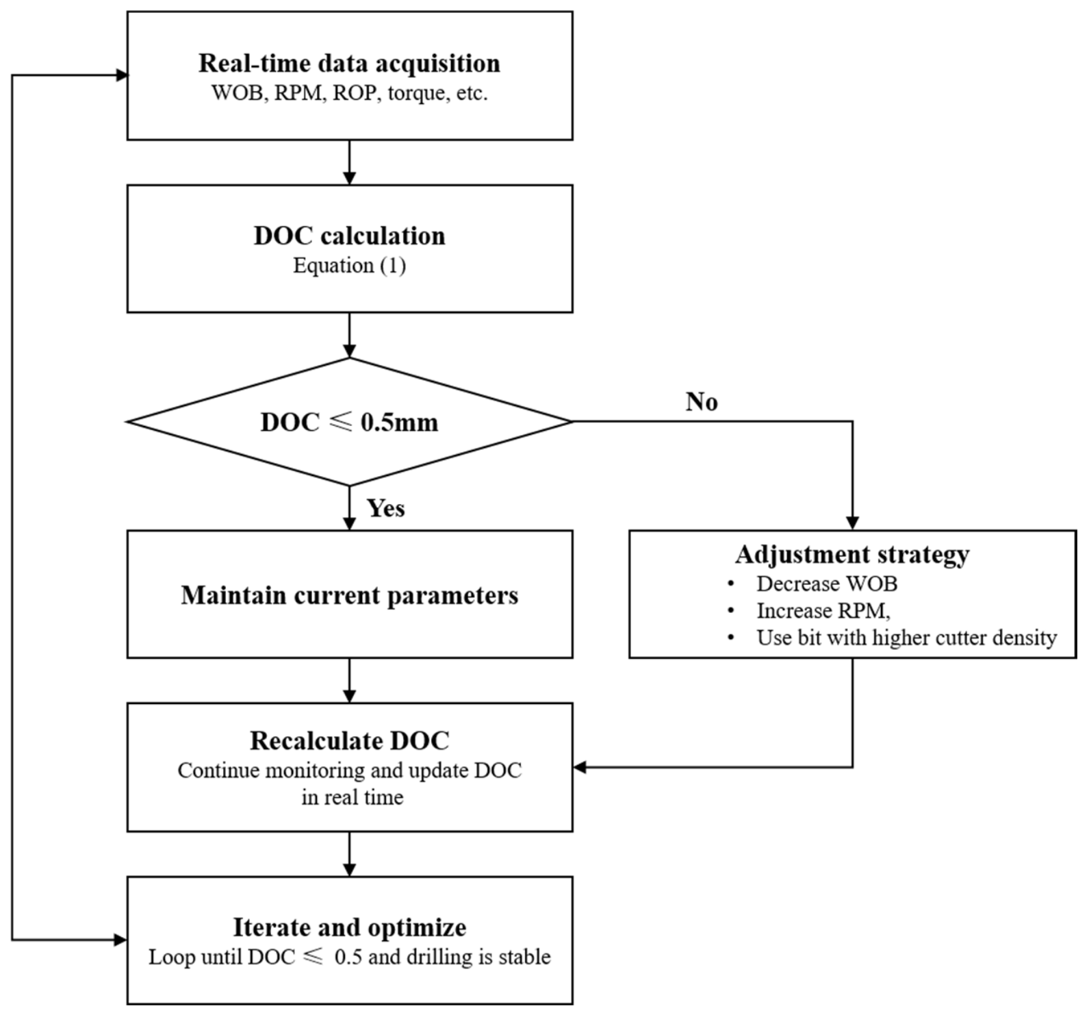
Although DOC is not directly measured in field operations, it can be dynamically estimated in real time using routinely monitored drilling parameters and bit configuration information. Consequently, DOC can be used as a practical engineering indicator for diagnosing drilling performance and evaluating cutter–rock interaction conditions. When the calculated DOC deviates from the desired operating range, corrective actions may be implemented. If DOC is too low, WOB can be increased, or RPM reduced, to enhance cutter penetration and improve rock-breaking efficiency. Conversely, if DOC becomes excessively high and is accompanied by severe vibration, torque fluctuations, or unstable drilling behavior, WOB may be reduced, or RPM increased, to maintain stable cutting conditions.
Therefore, rather than being regarded solely as an outcome parameter, DOC can serve as a diagnostic and optimization indicator that links surface drilling parameters with downhole rock-breaking behavior. A practical workflow for real-time DOC diagnosis and adjustment during drilling is illustrated in Figure 5.

4. Results and Analysis

4.1. Effects of WOB

Rock cutting size plays a critical role in determining borehole cleaning efficiency and drilling safety. To investigate the particle size distribution characteristics of coal-rock cuttings under different WOB conditions, the RPM and DOC were maintained at 55 rpm and 0.5 mm, respectively. The selected RPM represents a moderate rotary speed within the operational range commonly used in the study area. This ensures stable cutter–rock interaction while avoiding the excessive secondary fragmentation associated with high rotary speeds. Furthermore, the selected DOC of 0.5 mm corresponds to the shallowest penetration condition considered in this study. It was adopted as a reference case to provide stable cutting behavior and minimize penetration-depth effects. This experimental design facilitates a clearer evaluation of the independent influence of WOB on the drilled-cutting size characteristics. Accordingly, the WOB was set to 20, 40, 60, and 80 kN to simulate weak cutting, stable cutting, and aggressive cutting processes under low-WOB (20–40 kN), medium-WOB (40–60 kN), and high-WOB (60–80 kN) conditions, respectively. The total drilling distance was fixed at 30 mm.
The PFC simulations successfully reproduced the dynamic coal-rock cutting process during drilling. The results indicate that the drill bit effectively penetrated the coal rock, generating pronounced stress concentration zones beneath and ahead of the cutter. Under the combined effects of shear and tensile stresses, extensive breakage of the parallel bonds between particles occurred, leading to the brittle detachment of large coal-rock fragments from the parent rock. Consequently, flaky and blocky cuttings were generated. The entire cutting process was accompanied by periodic fluctuations in the cutting force.
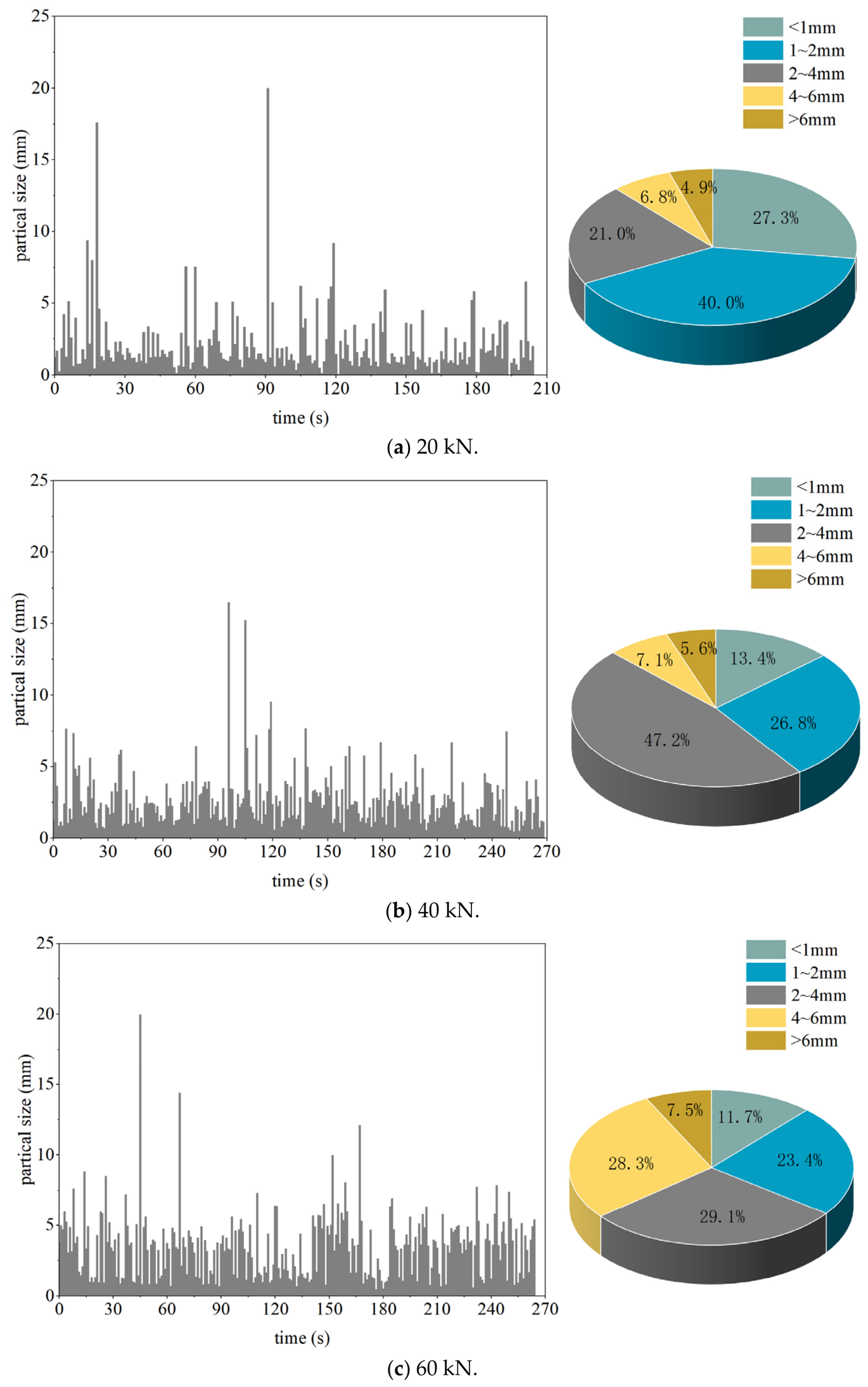
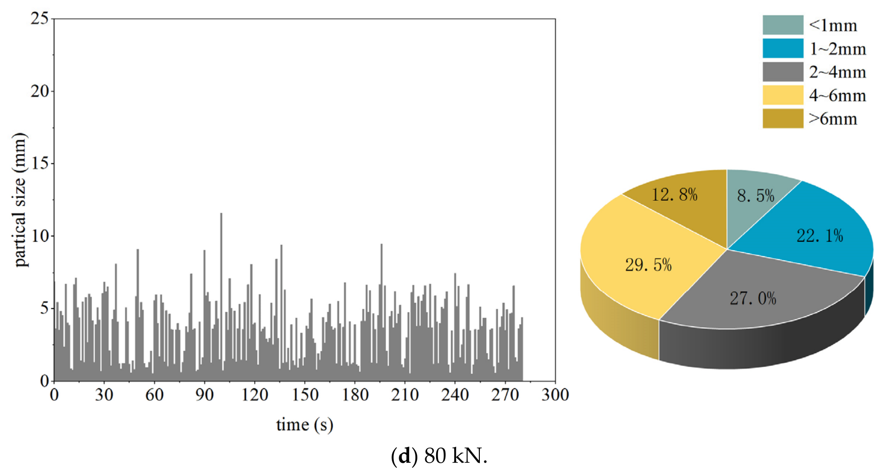
The temporal evolution of cutting size and the corresponding particle size distribution proportions under different WOB conditions are presented in Figure 6. The cuttings were classified into five size ranges, namely fine cuttings (<1 mm), small cuttings (1–2 mm), medium cuttings (2–4 mm), coarse cuttings (4–6 mm), and large cuttings (>6 mm), as summarized in Table 2.
As illustrated by the pie chart in Figure 6a, under the low-WOB condition of 20 kN, the generated cuttings were dominated by small cuttings (1–2 mm), accounting for 40.0% of the total cuttings. Fine cuttings (<1 mm) represented the second-largest proportion at 27.3%, followed by medium cuttings (2–4 mm) with a proportion of 21.0%. In contrast, coarse cuttings (4–6 mm) and large cuttings (>6 mm) accounted for relatively small proportions of 6.8% and 4.9%, respectively. These results indicate that, under relatively low cutting forces, the coal rock mainly undergoes localized fragmentation and progressive chipping, resulting predominantly in fine-to-medium-sized cuttings.
As shown in Figure 6b, when the WOB increased to 40 kN, the proportion of medium-sized cuttings (2–4 mm) increased significantly from 21.0% at 20 kN to 47.2%, becoming the dominant particle size category. Small cuttings (1–2 mm) accounted for the second-largest proportion at 26.8%, whereas the proportions of fine cuttings (<1 mm), coarse cuttings (4–6 mm), and large cuttings (>6 mm) remained relatively low, accounting for 13.4%, 7.1%, and 5.6%, respectively. This result indicates that increasing the WOB promoted more effective brittle fragmentation of the coal rock, leading to the generation of a larger proportion of medium-sized cuttings.
As illustrated in Figure 6c, when the WOB further increased to 60 kN, medium-sized cuttings and coarse cuttings became the two dominant particle size fractions, accounting for 29.1% and 28.3%, respectively. Their proportions were nearly identical, suggesting a transition from localized fragmentation to large-scale brittle spalling under medium-to-high drilling loads. Small cuttings accounted for 23.4%, whereas fine cuttings and large cuttings represented relatively small proportions of 11.7% and 7.5%, respectively.
As shown in Figure 6d, under the high-WOB condition of 80 kN, the proportion of coarse cuttings exceeded that of medium-sized cuttings, reaching 29.5% and 27.0%, respectively. Small cuttings remained the third-largest fraction, accounting for 22.1%. In contrast, fine cuttings and large cuttings accounted for 8.5% and 12.8%, respectively, with the proportion of large cuttings surpassing that of fine cuttings. This phenomenon indicates that excessive WOB intensified large-scale brittle failure and block spalling of the coal rock, resulting in the generation of more oversized cuttings. Such large cuttings may adversely affect borehole cleaning efficiency and increase the risk of downhole complications during drilling operations.
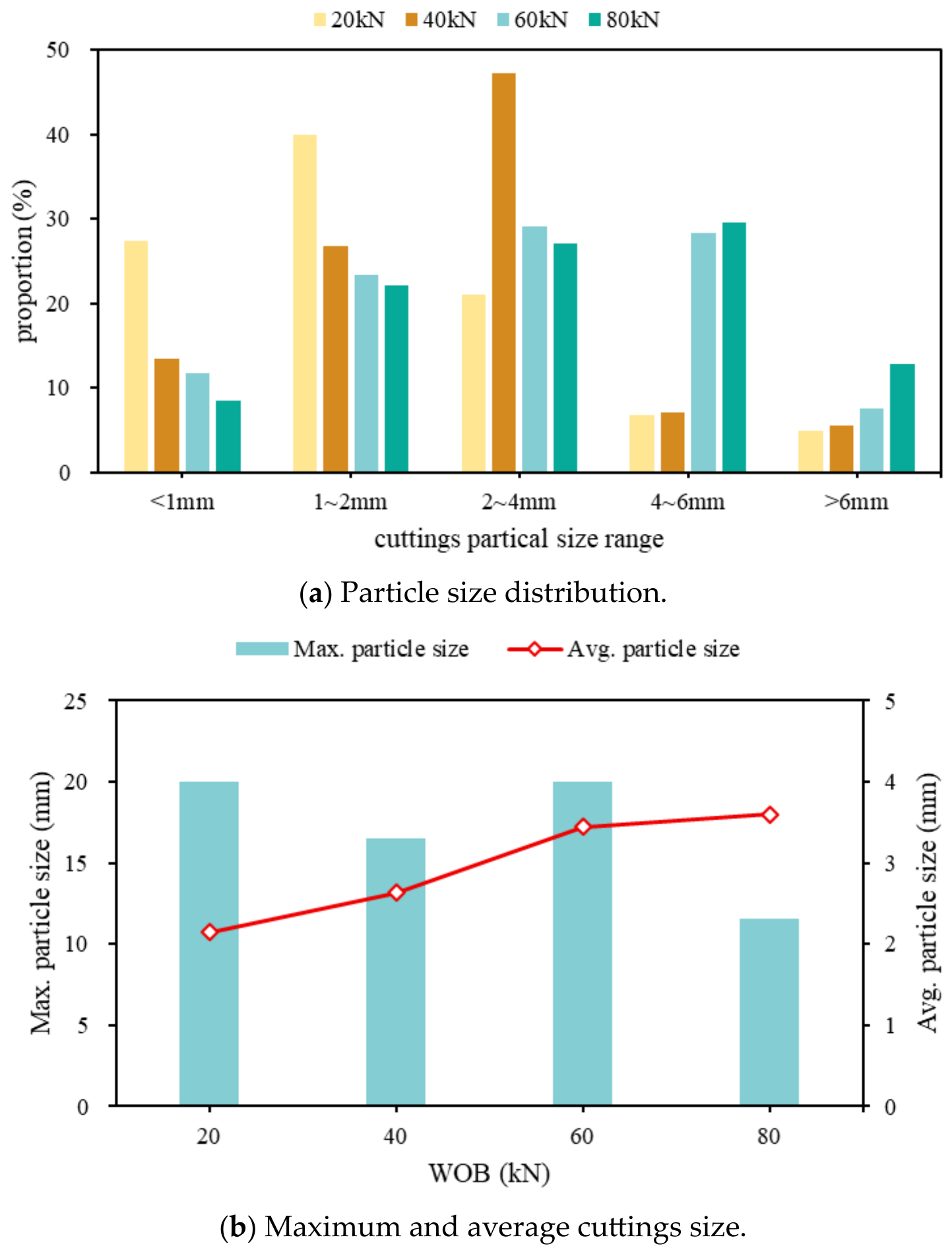
The effects of WOB on the drilled-cuttings size characteristics are shown in Figure 7. As illustrated in Figure 7a, under the low-WOB condition of 20 kN, the generated cuttings were mainly composed of fine and small cuttings, accounting for 67.3% of the total cuttings. When the WOB increased to 40 kN, the dominant particle size ranges shifted to small and medium cuttings, with a combined proportion of 74.0%. As the WOB further increased to 60 kN, the cuttings were primarily distributed within the 1~6 mm size range, and the combined proportion of small, medium, and coarse cuttings reached 80.8%. Under the strong cutting condition of 80 kN, the generated cuttings were still dominated by the 1~6 mm size range, while the proportion of large cuttings reached 12.8%. These results indicate that the overall particle size of the drilled cuttings increased with increasing WOB. Therefore, under high-WOB drilling conditions, the drilling fluid circulation rate should be appropriately increased to ensure effective hole cleaning.
Furthermore, Figure 7b shows that the average cutting size was 2.1 mm at a WOB of 20 kN. Compared with the 20 kN condition, the average cutting size increased by 25.5%, 64.0%, and 71.4% at WOBs of 40, 60, and 80 kN, respectively, although the growth rate gradually slowed at higher WOB. Under the low WOB condition of 20 kN, coal rock mainly experienced shallow local spalling. Although fine cuttings dominated overall, several relatively large cuttings could still be generated along natural fractures and bedding planes, resulting in a relatively large maximum particle size. As the WOB increased to 40~60 kN, the cutter penetration depth increased, and crack coalescence became more pronounced, promoting the transition of coal-rock failure from local fragmentation to block spalling. Consequently, the average cutting size increased significantly, and stable large cuttings were generated under the 60 kN condition, leading to a further increase in the maximum particle size. However, when the WOB further increased to 80 kN, localized crushing and secondary fragmentation became dominant. Large cuttings generated during the initial failure stage were subsequently crushed by repeated cutter interactions and particle collisions, causing the maximum particle size to decrease. Meanwhile, the proportion of medium- and coarse-sized cuttings continued to increase, resulting in a continued increase in the average particle size, although the increment became significantly smaller.
The effect of WOB on the cutting PSD obtained in this study aligns well with previous investigations of rock drilling and fragmentation. Xiao et al. experimentally demonstrated that ROP increased with increasing WOB, and that larger cuttings were generated as WOB and the mechanical penetration rate increased [24,25]. Their study further showed that greater axial bit–rock vibration amplitudes promoted the formation of larger fractures and, consequently, produced larger cuttings. Similarly, Reyes et al. reported a predominantly positive relationship between ROP and cuttings size, indicating that increased rock-removal efficiency is generally accompanied by the generation of larger fragments. However, they also noted that for highly brittle formations with pronounced laminated structures, such as gray shale, this relationship may become negative when the WOB exceeds a critical threshold, owing to changes in the rock-failure mechanism and fragmentation behavior [26]. Consistent with these findings, the DEM results reveal that increasing WOB shifts the PSD toward coarser particle sizes, with the proportions of coarse and large cuttings increasing significantly under high-WOB conditions. Mechanistically, a higher WOB increases the contact force and stress concentration beneath the cutter, facilitating crack propagation and fracture coalescence over a larger volume of the coal rock. As a result, larger fragments are detached during the cutting process. Compared with the vibration-assisted drilling experiments reported by Xiao et al. and the field-based observations reported by Reyes et al., the present study focuses on coal-rock formations and provides a particle-scale interpretation of how WOB governs PSD evolution through fracture development and fragment detachment. These results further confirm that WOB is a key parameter controlling cutting size and rock fragmentation efficiency during drilling.
From an operational perspective, this shift towards coarser cuttings has direct implications for wellbore hydraulics. According to classical cutting transport mechanics, the terminal slip velocity of a particle is highly dependent on its equivalent diameter. The significant increase in the proportion of coarse cuttings (4–6 mm) and large cuttings (>6 mm) under high-WOB conditions (60–80 kN) intrinsically leads to higher settling tendencies. If the annular fluid velocity and transport capacity are not proportionally enhanced, these coarse particles will rapidly settle on the low side of the horizontal wellbore. This phenomenon significantly increases the potential risk of cutting-bed accumulation and subsequent mechanical sticking. Therefore, under high-WOB drilling conditions, the drilling fluid circulation rate and rheological properties should be appropriately optimized to ensure effective hole cleaning.

4.2. Effects of RPM

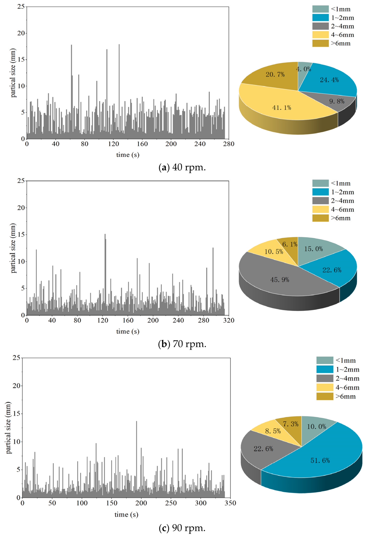
Investigating the evolution of drilled cutting size under different rotary speeds is essential for understanding how dynamic loading frequency governs coal-rock fragmentation. Unlike WOB, which primarily dictates vertical penetration and static loading intensity, rotary speed determines the frequency of cutter–rock interactions. To investigate its independent influence under aggressive cutting conditions—where the secondary fragmentation discussed in Section 4.1 began to emerge—the WOB and DOC were maintained at 80 kN and 0.5 mm, respectively. The rotary speeds were set to 40, 55, 70, and 90 rpm to simulate conditions ranging from slow to rapid cutting. The temporal evolution curves of cutting size and the corresponding size distribution proportions are presented in Figure 8 (for 40, 70, and 90 rpm) and Figure 6d (for 55 rpm), while the overall statistical effects are summarized in Figure 9.
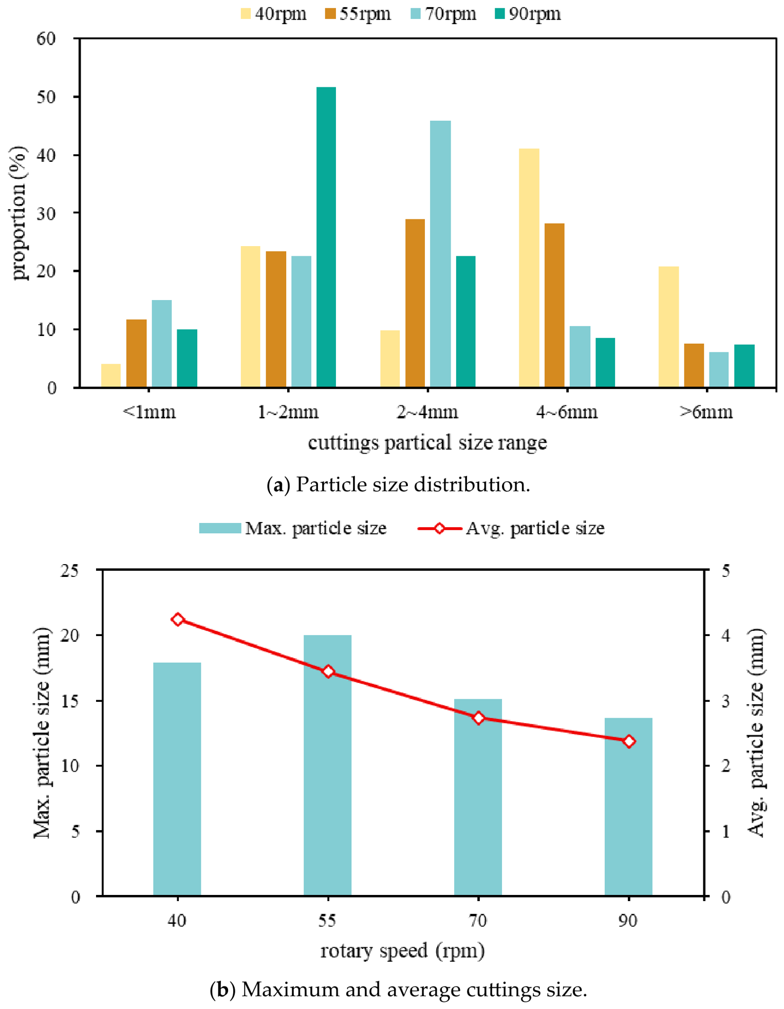
As observed in Figure 8 and Figure 9a, the dominant cutting size transitioned progressively from coarse to fine as the RPM increased. At a low rotary speed of 40 rpm, coarse cuttings dominated the distribution, accounting for 41.1% of the total, followed by small cuttings (24.4%) and large cuttings (20.7%). When the speed increased to 55 rpm, the proportion of coarse cuttings dropped by 11.6%, while medium cuttings increased significantly to 27.0%. At 70 rpm, medium cuttings became the most abundant fraction (45.9%). When the speed reached 90 rpm, the size distribution shifted drastically, with small cuttings sharply increasing to 51.6%, dominating the fragmentation products.
Mechanically, this distinct transition is governed by the time available for crack propagation and the intensity of secondary fragmentation. At lower rotary speeds (e.g., 40–55 rpm), the cutter interacts with the rock at a lower frequency. This allows sufficient time for internal stresses to accumulate and for primary cracks to propagate deeply and coalesce, favoring large-scale bulk spalling. Conversely, under high-RPM conditions (e.g., 70–90 rpm), the rock experiences rapid, high-frequency impacts. Because macroscopic cracks do not have adequate time to propagate fully before the next cutter engagement, the fragmentation mode shifts toward the formation of multiple short, localized fractures. Furthermore, similar to the localized crushing observed under the high-WOB condition (80 kN) in Section 4.1, high rotational speeds limit the time available for cuttings to clear the cutting face. As a result, newly detached rock blocks are repeatedly struck and crushed by the cutters before they can be evacuated, leading to severe secondary fragmentation (regrinding). This explains the significant refinement of cuttings at 90 rpm.
The statistical trends in Figure 9b further support this mechanical transition. The average cutting size exhibited a continuous decline with increasing RPM, dropping from 4.3 mm at 40 rpm to approximately 2.4 mm at 90 rpm (a 44.1% reduction). Interestingly, the maximum cutting size showed an initial increase followed by a decrease. The initial increase under a moderate RPM (55 rpm) suggests that the slightly elevated loading rate promoted the localized detachment of certain larger blocks. However, as the rotary speed continued to increase to 70 and 90 rpm, the intensified regrinding effect and particle collisions caused these large blocks to be systematically destroyed, ultimately reducing both the maximum and average particle sizes. This indicates that RPM governs a transition in the fragmentation regime, which is driven by the competition between the crack propagation time scale and the cutter impact frequency. Therefore, to minimize the overall cutting size and prevent the generation of excessively large blocks that impair hole-cleaning efficiency, the rotary speed in such coal-rock formations should be optimally controlled within the 70–90 rpm range.
The influence of RPM on the cutting PSD observed in this study is generally consistent with previous experimental investigations of rock drilling. Earlier studies reported that medium rotation rates tend to produce a wider particle size distribution, whereas high rotation rates generate a more concentrated PSD [27]. A similar trend was observed in the present study, where increasing the RPM progressively shifted the PSD from coarse-particle dominance toward a distribution dominated by medium and small particles. Previous researchers also found that the average particle size initially decreases with increasing RPM because of enhanced fragmentation efficiency [28]. However, excessively high rotation rates may promote the accumulation and agglomeration of fine particles, which can hinder the further breakage of coarse fragments and result in a subsequent increase in the average particle size. Although particle agglomeration was not explicitly considered in the current DEM model, both studies indicate that RPM primarily affects the cutting PSD through repeated cutting and secondary fragmentation processes. Compared with previous limestone drilling studies, the present work further demonstrates the sensitivity of coal-rock cuttings to RPM variations and provides a mechanistic explanation based on DEM-observed fragmentation behavior.

4.3. Effects of DOC

Investigating the evolution of drilled cutting size distribution under different DOC is essential for elucidating the fundamental geometrical and kinematic mechanisms governing cutter–rock interaction. As a direct bridge between WOB and rock-breaking behavior, DOC controls the penetration volume during a single cutting event and determines the spatial extent of crack initiation and propagation, thereby directly influencing the theoretical maximum size and distribution characteristics of the generated cuttings. In essence, DOC governs the geometric constraints and fragmentation scale of coal-rock failure. Therefore, it should not merely be regarded as a resultant operational parameter, but rather as a critical engineering indicator that can be proactively designed and dynamically diagnosed to achieve precise and predictable drilling performance.
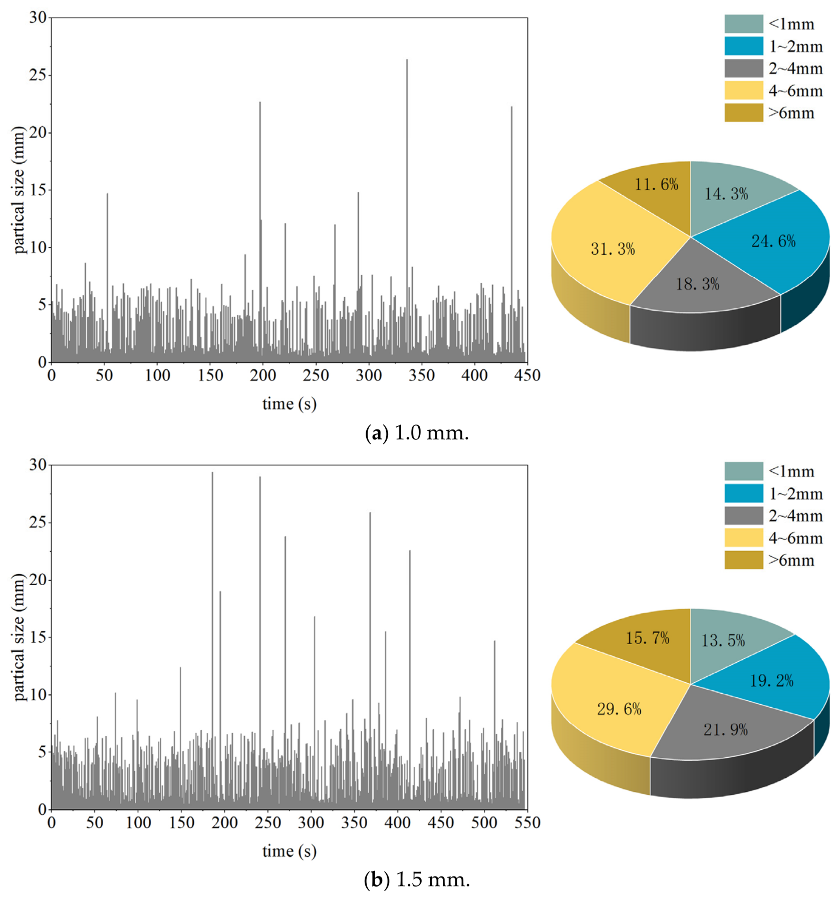
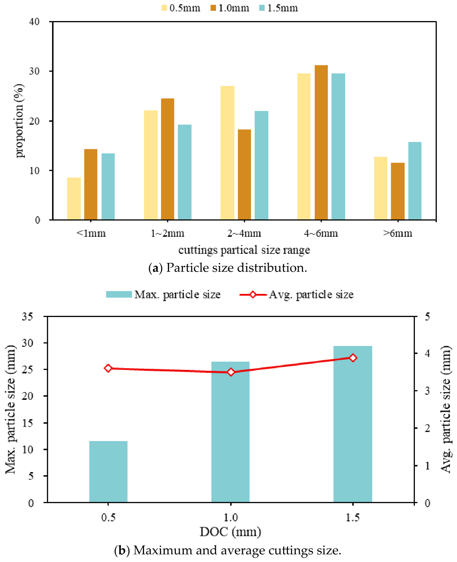
To investigate the influence of DOC on drilled cutting characteristics, the WOB and rotary speed were maintained constant at a constant 80 kN and 55 rpm, respectively. The DOC values were set to 0.5, 1.0, and 1.5 mm to simulate shallow, intermediate, and deep penetration conditions during coal-rock fragmentation and cutting generation. The total drilling distance was fixed at 30 mm. The temporal evolution curves of the cuttings’ particle size and the corresponding size distribution proportions obtained from the PFC simulation at a DOC of 0.5 mm are shown in Figure 6d, whereas the results for DOC values of 1.0 and 1.5 mm are presented in Figure 10.
As shown in Figure 6d, when the DOC was 0.5 mm, the proportions of small cuttings, medium cuttings, and coarse cuttings were all distributed within the range of 20–30%, and their combined proportion reached 78.2%, indicating that the generated cuttings were primarily concentrated within the 1–6 mm particle size range. Under this shallow penetration condition, the cutter–rock interaction mainly induced localized brittle fragmentation, while the relatively small penetration volume limited the propagation distance of cracks and suppressed excessive block spalling, resulting in a relatively concentrated intermediate particle size distribution.
As shown in Figure 10a, when the DOC increased to 1.0 mm, the proportion of medium cuttings decreased by 8.7%, whereas the proportion of fine cuttings increased by 5.7%. Meanwhile, the proportion of cuttings within the 1–6 mm size range remained relatively high at 74.1%. This result indicates that increasing the DOC enhanced the penetration and shearing effects of the cutter, thereby intensifying crack propagation and particle interaction. Consequently, a portion of the medium-sized cuttings underwent secondary fragmentation, resulting in an increase in fine cuttings.
As illustrated in Figure 10b, when the DOC further increased to 1.5 mm, the proportions of medium and small cuttings decreased by 5.1% and 2.9%, respectively, compared with those at a DOC of 0.5 mm. In contrast, the proportions of fine and large cuttings increased by 5.0% and 2.9%, respectively, while the proportion of cuttings within the 1–6 mm size range decreased to 70.7%. This phenomenon suggests that under deep penetration conditions, the rock-breaking mechanism gradually evolved toward a coupled mode characterized by localized crushing and large-scale block spalling. First, the increased penetration depth enlarged the single-cutting fragmentation volume and promoted crack coalescence over a larger spatial range, thereby facilitating the formation of large blocky cuttings. Second, the intensified extrusion and repeated cutter–particle interactions enhanced secondary crushing effects, generating additional fine particles. As a result, the particle size distribution became increasingly polarized, with simultaneous increases in both fine and large cuttings.
The effects of DOC on drilled-cutting size characteristics are presented in Figure 11. As shown in Figure 11a, under all three DOC conditions, coarse cuttings within the 4–6 mm size range constituted the dominant cutting fraction, accounting for approximately one-third of the total cuttings. Small cuttings (1–2 mm) and medium cuttings (2–4 mm) represented the second most abundant fractions. The combined proportions of cuttings within the 1–6 mm size range were 78.6%, 74.1%, and 70.7% at DOC values of 0.5, 1.0, and 1.5 mm, respectively, exhibiting a gradual decreasing trend with increasing DOC. In contrast, the proportions of fine and large cuttings increased progressively as the DOC increased.
Figure 11b further highlights the distinct role of DOC in controlling drilled-cutting size characteristics. Unlike WOB, which primarily shifts the overall particle size distribution toward coarser cuttings, or rotary speed, which mainly affects the average particle size through repeated fragmentation, DOC directly governs the penetration volume and fracture scale generated during a single cutter–rock interaction. Consequently, DOC exerts the strongest influence on the maximum cutting size among the three drilling parameters investigated.
To summarize, as the DOC increased from 0.5 mm to 1.5 mm, the proportion of cuttings within the 1–6 mm size range gradually decreased from 78.6% to 70.7%, whereas both fine cuttings (<1 mm) and large cuttings (>6 mm) increased simultaneously. This evolution indicates that increasing DOC activates two competing fragmentation mechanisms. First, deeper cutter penetration enlarges the rock-removal volume and promotes long-distance crack propagation and crack coalescence, thereby increasing the probability of generating large blocky cuttings. Second, the intensified cutter–particle and particle–particle interactions associated with larger penetration depths enhance localized crushing and secondary fragmentation, producing additional fine particles. As a result, the cuttings’ size distribution progressively evolves from a concentrated intermediate-size distribution toward a polarized distribution characterized by simultaneous increases in both fine and large cuttings.
This dual-fragmentation mechanism explains why the maximum cutting size increased dramatically with DOC, whereas the average cutting size exhibited only limited variation. Specifically, increasing DOC from 0.5 mm to 1.5 mm increased the maximum cutting size from 11.6 mm to 29.4 mm, for a growth of approximately 153%, while the average cutting size increased by less than 10%. The substantial increase in maximum particle size reflects the enhanced formation of large detached blocks, whereas the relatively stable average particle size results from the offsetting effect of the simultaneously generated fine particles. Therefore, DOC primarily broadens the particle size distribution range rather than causing a uniform coarsening of the entire cuttings population.
From an engineering perspective, the pronounced sensitivity of maximum cutting size to DOC suggests that DOC can serve as a direct control parameter for managing oversized cutting generation. Excessively large DOC values may increase the occurrence of cuttings exceeding the practical control threshold of 15 mm, thereby increasing hole-cleaning requirements and cutting-bed formation risks in extended horizontal sections. Consequently, maintaining a relatively low DOC is beneficial for controlling cutting size and improving drilling operational stability.
The effect of DOC on the cutting PSD obtained in this study is in good agreement with previous experimental observations in rock drilling. Earlier studies demonstrated that increasing the penetration depth leads to a broader particle size distribution because a larger volume of rock participates in each cutting event, resulting in the generation of larger fragments [28]. Similarly, the DEM simulations show that increasing the DOC significantly expands the PSD range and promotes the formation of coarse and large cuttings. Previous research also reported that the average particle size increases with penetration depth, owing to the development of larger fracture networks and the detachment of larger rock fragments. The present results further confirm this trend and reveal that DOC exerts the strongest influence on maximum cutting size among the investigated drilling parameters. Compared with previous studies that primarily focused on limestone drilling, this study extends the analysis to coal-rock formations and provides a mechanistic interpretation of PSD evolution based on crack propagation, crack coalescence, and fragment detachment processes. These findings highlight the critical role of DOC in controlling fracture scale and cutting size characteristics during horizontal drilling in coal-rock gas reservoirs.

4.4. Coal-Rock Fragmentation Mechanism During PDC Cutting

The particle size distribution of drilled cuttings is a direct physical reflection of the coal-rock failure mechanism induced by the PDC cutter. Unlike homogeneous hard rock, coal formations are highly heterogeneous, characterized by weak cementation, natural cleats, and microfractures. These pre-existing structural flaws naturally dictate the paths of crack initiation and propagation.
When the cutter engages the formation, a pronounced stress concentration develops immediately ahead of the cutter tip. Combined normal and shear forces cause the internal rock bonds to fail, nucleating localized microcracks that initially generate only fine fragments. As the cutter penetrates deeper, this stress field expands. The microcracks multiply and coalesce into an interconnected fracture network that eventually propagates to the free surface, causing the bulk detachment of large coal-rock blocks.
However, the mechanical process does not end with bulk detachment. Before these primary rock fragments are evacuated from the bottom hole, they frequently collide with the cutter body, the wellbore wall, and other cuttings. This induces secondary fragmentation, which breaks the large primary blocks into smaller pieces. The final cutting PSD observed at the surface is, therefore, the net result of both primary fracture generation and subsequent secondary regrinding.
The DEM simulations reveal how specific surface drilling parameters shift the balance between these two distinct mechanisms. Specifically, WOB dictates the initial stress intensity and governs the overall volume of the primary fracture network. DOC acts as the primary geometric boundary, determining the maximum possible size of the detached rock blocks. Conversely, RPM dictates the frequency of cutter interactions, which directly controls the severity of the secondary regrinding.
While this failure sequence aligns with general brittle rock cutting mechanics, identifying the distinct roles of WOB, DOC, and RPM provides a highly practical engineering framework for coal-rock gas reservoirs. Understanding whether a specific parameter dominates primary fracture size or secondary regrinding allows field operators to actively adjust surface settings, target a specific cuttings geometry, and ultimately prevent hole-cleaning failures in extended horizontal sections.

5. Model Validation

The discrete element PFC numerical simulation method established in this study was further applied to optimize the drilling engineering parameters of a representative well in the target block. The designed horizontal section extended from 3185 to 4685 m, with a total planned horizontal length of 1500 m. Drilling operations were performed using a PDC bit combined with a downhole motor. Based on the established relationships between drilling parameters and cutting size characteristics, the optimal rotary speed for the target coal-seam interval was determined to be 70–90 rpm, with the objective of controlling the maximum cutting size below 15 mm. This optimization strategy was intended to improve hole-cleaning efficiency and reduce the risk of cutting accumulation and downhole sticking during drilling operations.
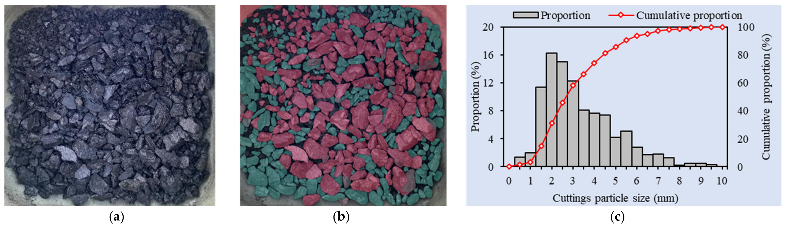
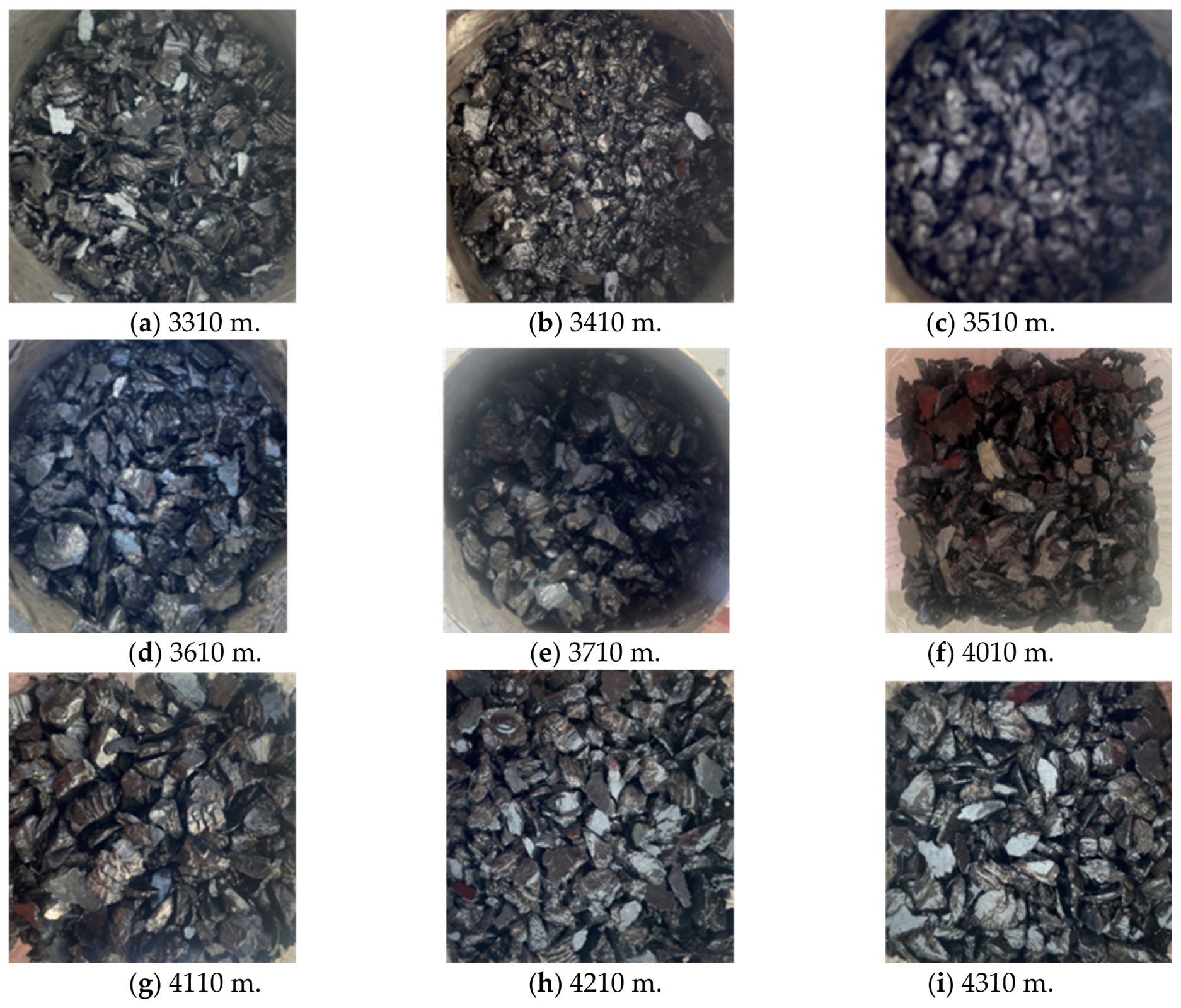
During real-time mud logging, the drill cuttings collected at the surface were quantitatively characterized using a static digital image analysis (DIA) method [29]. Individual cutting particles were identified through image segmentation, and their equivalent particle diameters were subsequently calculated to generate particle size distribution curves, as shown in Figure 12. Figure 13 presents the drilled cutting photographs for nine groups of samples collected from different well depths, while the corresponding particle size ranges are summarized in Table 3.
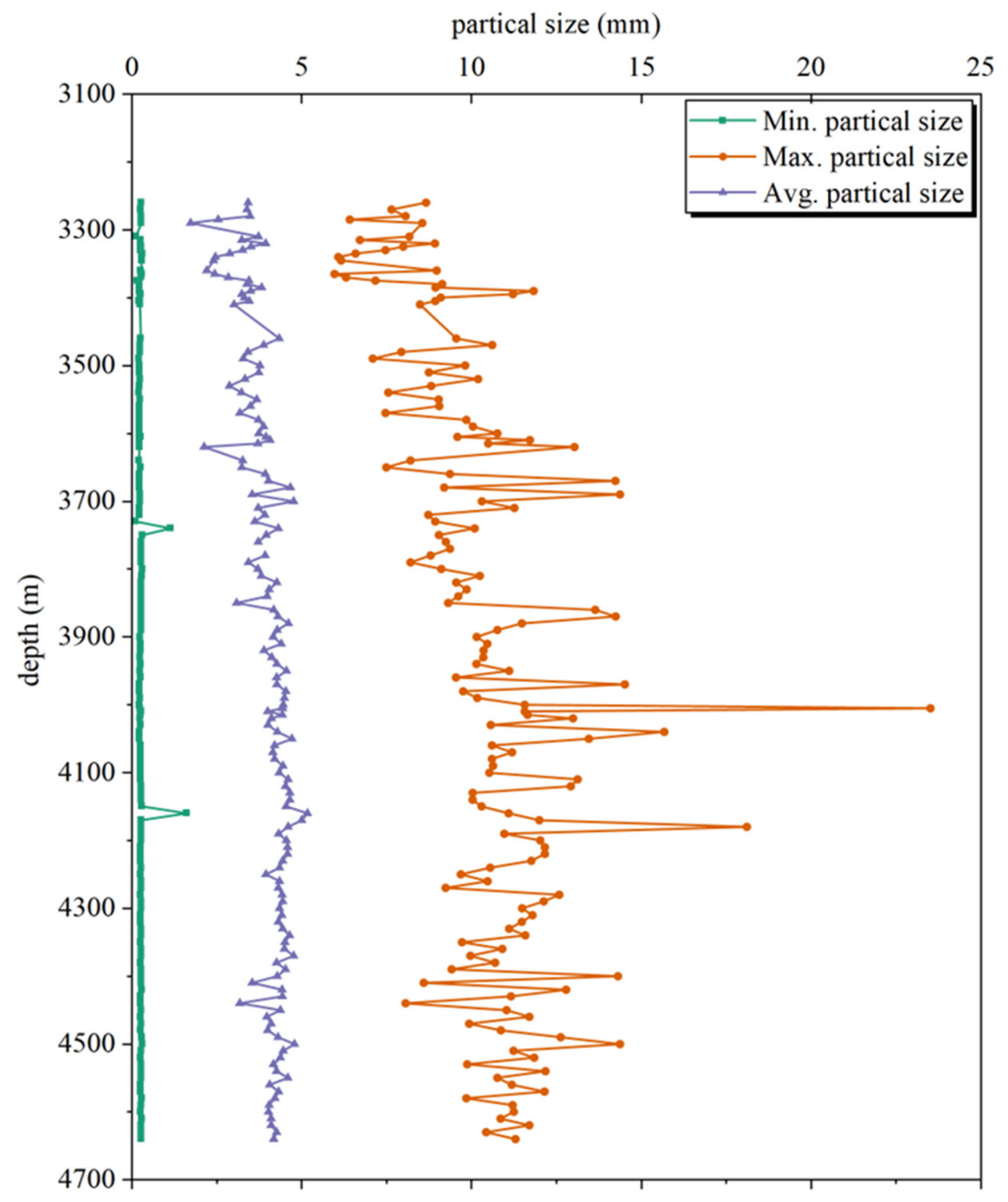
Based on the DIA, the maximum, minimum, and average particle sizes of the drilled cuttings at different well depths were determined, as shown in Figure 14. The statistical results indicate that the overall mean minimum, maximum, and average particle sizes throughout the entire horizontal section were 0.27 mm, 10.37 mm, and 3.96 mm, respectively. At well depths of 4005 m, 4040 m, and 4180 m, the maximum cutting sizes reached 23.51 mm, 15.67 mm, and 18.10 mm, respectively. An analysis of the geological and drilling logs suggests that the localized oversized cuttings were primarily generated during drilling through natural fracture zones. This process temporarily exacerbated block spalling. Nevertheless, the maximum cutting sizes in the remaining intervals were all below 15 mm. Overall, more than 98% of the drilled interval satisfied the designed cutting-size control criterion, demonstrating that the optimized drilling parameter scheme effectively reduced the risk of downhole sticking and contributed to improved drilling safety and hole-cleaning performance in the deep coal-rock horizontal well.
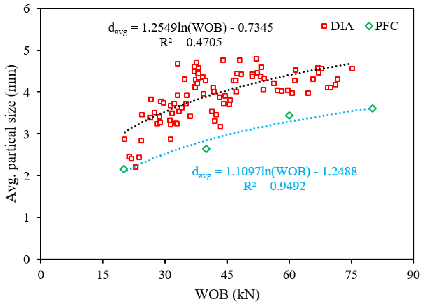
The comparison between the DEM–PFC predictions and DIA measurements indicates a relative error of approximately 32% in the average cutting size (Figure 15). This discrepancy is mainly attributed to the simplified representation of coal-rock properties and drilling conditions in the numerical model, whereas the field data are influenced by geological heterogeneity, natural fractures, bedding structures, and drilling–fluid interactions. Nevertheless, both the simulated and measured results exhibit a consistent logarithmic growth trend, demonstrating that the model successfully captures the dominant mechanism governing cutting-size evolution. Therefore, rather than relying on the DEM model for absolute particle size prediction, the optimized parameters (70–90 rpm) were derived by combining the model’s mechanistic insights—which dictate that higher RPM promotes secondary fragmentation—with the field-calibrated threshold of 15 mm.
To further evaluate the applicability of the recommended drilling parameters (70–90 rpm and a 0.5 mm penetration depth), field operational evidence from two representative extended horizontal wells was analyzed.
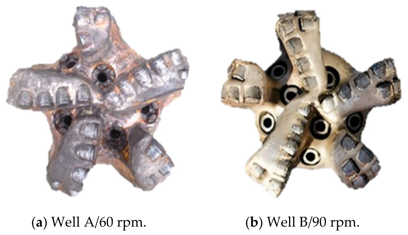
As shown in Figure 16, the PDC drill bit retrieved from Well A, drilled at 60 rpm over a 1479 m horizontal section (3030–4509 m), exhibits overall PDC cutter wear of approximately 0–1 mm. For Well B, drilled at 90 rpm over a 1481 m horizontal section (2944–4425 m), the retrieved bit shows no outer diameter reduction, no noticeable wear on the inner conical cutters, and only 1–3 mm of wear specifically on the nose and shoulder cutters, with the overall bit condition rated as good.
Although Well A (60 rpm) exhibited slightly lower bit wear, previous DEM analysis (Section 4.2) demonstrated that such moderate rotational speeds fail to induce sufficient secondary fragmentation, thereby increasing the risk of generating oversized cuttings (>15 mm). Conversely, the bit retrieved from Well B proves that within the recommended 70–90 rpm range, bit wear remains highly localized and within an acceptable level for field operations. When combined with the DEM–PFC results—which show that the maximum cutting size is effectively controlled below 15 mm under the same parameter range—the recommended drilling parameters demonstrate a balanced performance in terms of cutting size control, bit durability, and operational stability.
Therefore, the recommended parameter range of 70–90 rpm and a 0.5 mm penetration depth represent an optimal trade-off between hole-cleaning efficiency, rate of penetration, torque and vibration stability, and controlled bit wear, demonstrating its practical applicability for extended coal-rock horizontal wells.
To further enhance its engineering applicability, a practical cutting-size control threshold and corresponding operational measures are proposed. Based on field observations from the study area, a maximum cuttings size of 15 mm was adopted as the practical control threshold for deep coal-rock horizontal wells. When the maximum cutting size remains below this threshold, cuttings can generally be transported effectively by the drilling fluid, reducing the risk of cutting-bed accumulation and downhole sticking. Conversely, the occurrence of cuttings larger than 15 mm indicates a higher proportion of coarse particles, which may adversely affect hole-cleaning efficiency, particularly in extended horizontal sections.
Therefore, when cuttings exceeding 15 mm are continuously observed during mud logging, operational adjustments should be considered. Recommended measures include increasing the rotary speed to promote the secondary fragmentation of cuttings, enhancing the drilling–fluid circulation rate to improve annular transport capacity, and reducing the penetration depth or WOB when excessively large cuttings are generated. The continuous monitoring of the cutting size distribution can provide real-time feedback for drilling parameter optimization and hole-cleaning management.

6. Conclusions

In this study, the particle size distribution (PSD) characteristics of drill cuttings generated during coal-rock drilling were systematically investigated using a DEM model calibrated against laboratory experiments. The effects of drilling parameters on cutting fragmentation behavior and PSD evolution were quantified, and the underlying coal-rock fragmentation mechanisms were analyzed. The main conclusions are as follows:
(1)
The drilling parameters exhibited distinct influences on cutting size characteristics. Based on the investigated parameter ranges, the relative influence on the maximum cutting size followed the order of DOC > WOB > rotational speed, whereas the influence on the average particle size followed the order of rotational speed > WOB > DOC. These results indicate that DOC primarily controls the scale of primary fracture generation, while rotational speed mainly governs secondary fragmentation and particle size refinement.
(2)
Coal-rock fragmentation during PDC cutting is governed by the coupled effects of primary brittle fracture and secondary particle breakage. DEM observations reveal a five-stage fragmentation process involving stress concentration, microcrack initiation, crack propagation and coalescence, fragment detachment, and secondary fragmentation. The final PSD is determined by the interaction between these two fragmentation mechanisms. Within this framework, DOC controls the fracture scale, WOB affects fracture intensity, and rotational speed regulates the degree of secondary fragmentation.
(3)
Increasing DOC from 0.5 mm to 1.5 mm significantly increased the maximum cuttings size from 11.6 mm to 29.4 mm, while having little effect on the average particle size. Larger DOC values promoted the generation of oversized cuttings. Increasing WOB enlarged the overall cutting size and increased the proportion of medium-to-coarse particles, although the increase in particle size became less pronounced under high-WOB conditions because of secondary crushing. Under WOB conditions of 60–80 kN, the proportion of 4–6 mm cuttings increased by more than 20% compared with that at 40 kN, suggesting higher hole-cleaning requirements and a greater tendency for cutting accumulation during horizontal drilling.
(4)
Rotational speed exhibited a pronounced refining effect on the PSD. As the rotational speed increased from 40 rpm to 90 rpm, the maximum cutting size decreased from 20.0 mm to 13.7 mm, and the average particle size showed an overall decreasing trend. Higher rotational speeds enhanced repeated cutter engagement and secondary fragmentation, resulting in a transition from coarse-particle-dominated distributions to fine-particle-dominated distributions. Within the investigated conditions, rotational speeds of 70–90 rpm were found to be favorable for reducing oversized cuttings and improving cutting transportability.
(5)
The proposed DEM–PFC-based methodology was validated using cutting samples collected from a coal-rock gas horizontal well. Among the 146 analyzed samples, only three exceeded the maximum particle size threshold of 15 mm, and approximately 98% satisfied the target criterion. The field results provide supporting evidence for the potential effectiveness of the proposed approach in drilling parameter optimization, cutting-size control, and hole-cleaning risk management for coal-rock gas horizontal wells.

Author Contributions

Conceptualization, Y.Z.; methodology and writing—review and editing, G.L.; methodology, M.C.; writing—original draft and writing—review and editing, H.W.; software and investigation, X.W. All authors have read and agreed to the published version of the manuscript.

Funding

This work was supported by the National Science and Technology Major Project “Intelligent Drilling Optimization and Autonomous Decision-Making Industrial Control System” (Grant No. 2024ZD1401806), the CNPC Science and Technology Special Project: Research and Development of Key Technologies for DrillingOps Twin (Grant No. 2025ZG06-02), and the Open Fund of State Key Laboratory for Fine Exploration and Intelligent Development of Coal Resources (Grant No. SKLCRSM24KFA06).

Data Availability Statement

The original contributions presented in this study are included in the article. Further inquiries can be directed to the corresponding author.

Conflicts of Interest

Author Meng Cui was employed by the company CNPC Engineering Technology R&D Company Limited. Author Hua Wu was employed by the company CNPC Bohai Drilling Engineering Company Limited. The remaining authors declare that the research was conducted in the absence of any commercial or financial relationships that could be construed as a potential conflict of interest.

Abbreviations

The following abbreviations are used in this manuscript:
PSDParticle size distribution
DEMDiscrete element method
PFCParticle flow code
WOBWeight on bit
DOCDepth of cut
ROPRate of penetration
UCSUniaxial compressive strength
EYoung’s modulus
νPoisson’s ratio
DIADigital image analysis

References

  1. Wang, B.; Li, F.; Tian, B.; Xu, B.; Cheng, Y. Analytical method and damage evolution mechanism of coal and rock bursting based on Hamiltonian mechanics. Int. J. Min. Sci. Technol. 2025, 10, 983–995. [Google Scholar] [CrossRef]
  2. Li, G.; Zhang, S.; He, H.; He, X.; Zhao, Z.; Niu, X.; Xiong, X.; Zhao, Q.; Guo, X.; Hou, Y.; et al. Coal-rock gas: Concept, connotation and classification criteria. Pet. Explor. Dev. 2024, 51, 897–911. [Google Scholar] [CrossRef]
  3. Zhu, J.; Chen, M.; Wang, L.; Sun, H.; Wang, C.; Azhar, N.; Oduro, N.B. Characterization of 10 nm–10 μm coal dust particles generated by simulated different cutting and drilling parameters: Mass concentration distribution, number concentration distribution, and fractal dimension. Int. J. Coal Sci. Technol. 2023, 10, 89. [Google Scholar] [CrossRef]
  4. Bageri, B.S.; Benaafi, M.; Mahmoud, M.; Mohamed, A.; Patil, S.; Elkatatny, S. Effect of Formation Cutting’s Mechanical Properties on Drilling Fluid Properties During Drilling Operations. Arab. J. Sci. Eng. 2020, 45, 7763–7772. [Google Scholar] [CrossRef]
  5. Yin, Y.; Zhang, Q.; Guo, L.; Wang, C.; He, S.; Zhang, D. Drill Cuttings Test of Coal Under Different Stresses and Characteristics of Coal Particle Distribution During Borehole Collapse. Processes 2025, 13, 499. [Google Scholar] [CrossRef]
  6. An, J.; Li, J.; Huang, H.; Zhang, H. Analysis of Cuttings Transport in Small-Bore Horizontal Wells Considering Drill String Eccentricity. Energy Sci. Eng. 2025, 13, 3088–3106. [Google Scholar] [CrossRef]
  7. Jiang, F.; Wu, W.; Wang, X.; Zhu, H.; Du, Y.; Wang, A. A Novel Continuous-Discontinuous Deformation Analysis for Full-Process Rock Fracture Modeling with Dynamic Contacts and Data-Driven Constitutive. Comput. Geotech. 2026, 191, 107810. [Google Scholar] [CrossRef]
  8. Li, H.; Feng, J.; Su, D.; Chen, X.; Guo, X. A review of computational approaches for simulating fracturing mechanisms in layered rock formations. Int. J. Coal Sci. Technol. 2025, 12, 99. [Google Scholar] [CrossRef]
  9. Zhao, W.; Huang, R.; Yan, M. Mechanical and fracture behavior of rock mass with parallel concentrated joints with different dip angle and number based on PFC simulation. Geomech. Eng. 2015, 8, 757–767. [Google Scholar] [CrossRef]
  10. Wei, J.; Wang, S.; Song, S.; Sun, Q. Numerical simulation on evolution law of overburden fractures and surface cracks in crossing ditch mining of shallow coal seam. Coal Geol. Explor. 2022, 50, 67–75. [Google Scholar] [CrossRef]
  11. Wu, Z.; Cheng, Y.; Yuan, R. Numerical Simulation of Rock Cracking Using Saddle Polycrystalline Diamond Compact Cutters Considering Confined Pressure and Mechanism of Speed Increase. Processes 2024, 12, 1450. [Google Scholar] [CrossRef]
  12. Ramba, V.; Selvaraju, S.; Subbiah, S.; Palanisamy, M.; Srivastava, A. Optimization of drilling parameters using improved play-back methodology. J. Pet. Sci. Eng. 2021, 206, 108991. [Google Scholar] [CrossRef]
  13. Lu, Z.; Wu, B.; Shi, J.; Xi, C.; Wei, K. A Multiparameter Coupled Prediction Model for Annular Cuttings Bed Height in Horizontal Wells. Geofluids 2022, 2022, 9938546. [Google Scholar] [CrossRef]
  14. Pang, B.; Ren, X.; Liu, Z.; Wang, X.; Liu, X. Investigation on multiphase flow of multi-size cuttings particles and non-Newtonian drilling fluids in oil and gas horizontal well drilling using kinetic theory of granular flow. Energy 2023, 282, 128878. [Google Scholar] [CrossRef]
  15. Song, S.; Fei, S.; Zhang, Y.; Huang, Y.; Meng, P.; Cui, Y.; Chen, Y. Classification and evaluation of CBM reservoirs and efficient development strategies based on drilling parameters: A case study of the No. 8 coal of the Benxi Formation in the Ordos Basin. Nat. Gas Geosci. 2025, 36, 1779–1790. [Google Scholar]
  16. Lin, W.; Cong, P.; Wang, H.; Wei, Z.; Yang, Y.; Me, Z.; Qu, L.; Ma, L.; Wang, L. Application and discussion of geological guidance technology for deep coalbed methane horizontal wells: A case study of block X in Shenmu gas field, Ordos Basin. P. Reserv. Eval. Dev. 2025, 15, 300–309. [Google Scholar] [CrossRef]
  17. Fei, S.; Hou, Y.; Zhang, Z.; Chen, H.; Zhang, L.; Long, B.; Cui, Y.; Zhong, G.; Wang, Y.; Qiang, Z. Differentiated and refine geosteering methods for coal-rock gas horizontal wells and their applications in the eastern Ordos Basin. J. Nat. Gas Geosci. 2025, 36, 985–999. [Google Scholar] [CrossRef]
  18. Xu, F.; Nie, Z.; Sun, W.; Xiong, X.; Xu, B.; Zhang, L.; Shi, X.; Liu, Y.; Liu, S.; Zhao, Z.; et al. Theoretical and technological system for Highly efficient development of deep coalbed methane in the Eastern edge of Erdos Basin. J. China Coal Soc. 2024, 49, 528−544. [Google Scholar] [CrossRef]
  19. Fan, Z.; Shi, J.; Wang, C.; Hao, P.; Wang, Y.; Wang, T.; Wang, X.; Dai, H.; Yang, B.; Cao, J. Experimental study of permeability stress sensitivity and velocity sensitivity of deep coal seams in Linxing–Shenfu block, Ordos Basin. China Pet. Explor. 2025, 30, 141–159. [Google Scholar]
  20. Su, L.; Li, H.; Chi, Q.; Yang, X.; Gao, X.; Huang, X. Dynamic damage and crack propagation of granite under thermal shock: DEM modeling insights. Sci. Rep. 2026, 16, 4054. [Google Scholar] [CrossRef] [PubMed]
  21. Jia, Q.; Liu, X.; Tan, X. Crack evolution mechanism of stratified rock mass under different strength ratios and soft layer thickness: Insights from DEM modeling. Soils Found. 2024, 64, 101534. [Google Scholar] [CrossRef]
  22. Xia, K.; Ren, R.; Liu, F. Numerical analysis of mechanical behavior of stratified rocks containing a single flaw by utilizing the particle flow code. Eng. Anal. Bound. Elem. 2022, 137, 91–104. [Google Scholar] [CrossRef]
  23. Fu, Z.; Tergeist, M.; Kueck, A.; Ostermeyer, G.P. Investigation of the cutting force response to a PDC cutter in rock using the discrete element method. J. Pet. Sci. Eng. 2022, 213, 110330. [Google Scholar] [CrossRef]
  24. Xiao, Y.; Hurich, C.; Molgaard, J.; Butt, S.D. Investigation of active vibration drilling using acoustic emission and cutting size analysis. J. Rock Mech. Geotech. Eng. 2018, 10, 390–401. [Google Scholar] [CrossRef]
  25. Ahmed, D.; Xiao, Y.; Moura, J.; Butt, S. Investigation of Hole Widening Drilling Using Cutting Analysis. In Proceedings of the 72nd Canadian Geotechnical Society Annual Conference, St. John’s, NL, Canada, 29 September–2 October 2019; Available online: https://www.researchgate.net/publication/351065537_Investigation_of_Hole_Widening_Drilling_Using_Cutting_Analysis (accessed on 20 June 2026).
  26. Reyes, R.; Kyzym, I.; Rana, P.; Molgaard, J.; Butt, S. Cuttings Analysis for Rotary Drilling Penetration Mechanisms and Performance Evaluation. In Proceedings of the 49th U.S. Rock Mechanics/Geomechanics Symposium, San Francisco, CA, USA, 28 June–1 July 2015; Available online: https://onepetro.org/ARMAUSRMS/proceedings-abstract/ARMA15/ARMA15/ARMA-2015-764/66046 (accessed on 20 June 2026).
  27. Yang, X.; Nie, A.; Elsworth, D.; Zhou, J.; Tao, Y. Fractal Characteristics of Drilling Particle Size Distribution of Shale: A Laboratory Scale Investigation. Rock Mech. Rock Eng. 2022, 55, 5307–5319. [Google Scholar] [CrossRef]
  28. Yang, X.; Nie, A.; Zhou, J. Experimental investigation of the particle size distribution and the influence of operating parameters in limestone drilling. Int. J. Rock Mech. Min. Sci. 2021, 138, 104634. [Google Scholar] [CrossRef]
  29. Ismailova, L.; Dochkina, V.; Ibrahim, M.; Mezghani, M. Automated drill cuttings size estimation. J. Pet. Sci. Eng. 2022, 209, 109873. [Google Scholar] [CrossRef]
Figure 1. DEM-PFC modeling workflow for uniaxial compression tests.
Processes 14 02049 g001
Figure 2. Numerical simulation results of uniaxial compression: (a) Comparison of numerical and experimental stress–strain curves; (b) fracture propagation morphology, blue indicates shear fractures, whereas green indicates tensile fractures.
Processes 14 02049 g002
Figure 3. Numerical modeling workflow of drill-bit cutting in coal-rock.
Processes 14 02049 g003
Figure 4. Schematic diagram of cutting formation mechanism and particle size distribution characteristics during the cutting process: (a) Schematic of cutting process; (b) statistical distribution of cutting size; (c) schematic of cutting agglomeration behavior during cutting; (d) schematic of fracture propagation morphology during cutting.
Processes 14 02049 g004
Figure 5. Field workflow for real-time DOC diagnosis and adjustment during drilling.
Processes 14 02049 g005
Figure 6. Temporal variation in drilled cutting particle size and size fraction distribution under different WOB conditions.
Processes 14 02049 g006aProcesses 14 02049 g006b
Figure 7. Effects of WOB on drilled cutting size characteristics.
Processes 14 02049 g007
Figure 8. Temporal variation in drilled cutting particle size and size fraction distribution under different RPM.
Processes 14 02049 g008
Figure 9. Effects of RPM on drilled cutting size characteristics.
Processes 14 02049 g009
Figure 10. Temporal variation in drilled cutting particle size and size fraction distribution under different DOC.
Processes 14 02049 g010
Figure 11. Effects of DOC on drilled cutting size characteristics.
Processes 14 02049 g011
Figure 12. Process of digital image analysis for drill cuttings: (a) Original drill cuttings photograph; (b) segmentation and identification result; (c) particle size distribution histogram and cumulative proportion curve.
Processes 14 02049 g012
Figure 13. Drilled cutting photographs collected at different well depths.
Processes 14 02049 g013
Figure 14. Particle size characteristics of drill cuttings at different well depths.
Processes 14 02049 g014
Figure 15. Comparison of average cutting size predicted by DEM–PFC simulations and measured via DIA.
Processes 14 02049 g015
Figure 16. Field performance of PDC drill bits retrieved from extended horizontal wells.
Processes 14 02049 g016
Table 1. Uniaxial compression test results.
Core No. LithologyDensity (g/cm3)UCS (MPa)E (GPa)ν
DZ-1Coal rock1.3513.172.230.42
DZ-2Coal rock1.337.951.490.41
DZ-3Coal rock1.328.491.350.42
DZ-4Coal-gangue rock1.9321.342.010.38
DZ-5Coal-gangue rock1.920.342.140.41
DZ-6Coal-gangue rock2.1224.2919.320.35
Table 2. Classification criteria and engineering interpretation of coal-rock cutting particle size.
Size RangeCuttings ClassificationEngineering Interpretation
<1 mmFine cuttingsPowder-like and highly fragmented particles generated mainly by grinding and micro-fracturing
1~2 mmSmall cuttingsFine granular cuttings formed during stable local crushing
2~4 mmMedium cuttingsTypical effective cuttings generated by brittle fragmentation
4~6 mmCoarse cuttingsRelatively large cuttings produced by block spalling and macro-crack propagation
>6 mmLarge cuttingsLarge flaky or blocky fragments indicating strong brittle failure and aggressive cutting
Table 3. Particle size ranges of drilled cuttings collected at different well depths.
Well Depth (m)Particle Size Range (mm)
33100.21–8.17
34100.24–8.48
35100.23–8.74
36100.23–11.72
37100.22–11.26
40100.27–11.56
41100.25–13.12
42100.25–12.16
43100.26–11.79
Disclaimer/Publisher’s Note: The statements, opinions and data contained in all publications are solely those of the individual author(s) and contributor(s) and not of MDPI and/or the editor(s). MDPI and/or the editor(s) disclaim responsibility for any injury to people or property resulting from any ideas, methods, instructions or products referred to in the content.