Article

Research on Sealing Mechanism and Structural Optimization of Electrolysis Cell for Hydrogen Production by Electrolysis of Water


by
Huijun Xin
1,2,†,
Zudong Shen
3,†,
Zhaowang Dan
1,
Xiangnan Wang
1,
Minglei Hu
1,
Deng Wang
1,
Ende Yu
2,*,
Linlin Zhou
1,* and
Kuang Yun
1,*
1
Ocean Hydrogen Energy R&D Center, Research Institute of Tsinghua University in Shenzhen, Shenzhen 518063, China
2
School of Chemistry and Chemical Engineering, Southwest Petroleum University, Chengdu 610500, China
3
State Key Laboratory of Chemical Resource Engineering, College of Chemistry, University of Chemical Technology, Beijing 100029, China
*
Authors to whom correspondence should be addressed.
These authors contributed equally to this work.
Processes 2026, 14(12), 1969; https://doi.org/10.3390/pr14121969
Submission received: 9 April 2026 / Revised: 8 June 2026 / Accepted: 11 June 2026 / Published: 17 June 2026
(This article belongs to the Special Issue Green Bio-Hydrogen Energy and Biogas Production Technology)

Abstract

In order to optimize the sealing structure of the electrolytic cell for hydrogen production by electrolysis of water and enhance its sealing performance, a finite element model of the electrolytic cell sealing was established using software. The influence of different parameters of the sealing rib structure on the sealing performance was studied, and the variation law of gasket compressive stress under different sealing rib slot widths, angles, and spacings was explored. The results show that under the material constants of C10 = 7.0 × 10⁻³ and C01 = 6.05 in the Mooney–Rivlin constitutive model of the gasket, the gasket will deform and embed into the sealing rib groove after compression. At the same time, two parts of stress concentration will occur at the contact area between the gasket and the sealing rib groove, namely tensile stress concentration and compressive stress concentration. This stress concentration is the main source of sealing effect in practical work. After adding the sealing rib groove, the contact area between the sealing rib area and the gasket increases. When maximizing the peak sealing compressive stress serves as the optimization criterion, the optimal pitch settles at 0.4 mm; if the optimization objective shifts to attaining the utmost contact area, the preferable spacing amounts to 1 mm, accompanied by a maximum contact area increment of 34.31 percent. After comprehensive deliberation over sealing stress magnitude, functional sealing area, gas tightness efficiency as well as practical engineering applicability, 0.8 mm is pinpointed in this dissertation as the globally optimal spacing dimension. With a sealing rib pitch of 0.8 mm, a breadth of 1 mm, and an inclined angle of 20 degrees, the gasket yields substantial sealing stress alongside optimized post-assembly sealing contact area, wherein 26.44 percent of the overall gasket area contributes to effective sealing performance.

1. Introduction

Amid growing global energy demands and increasingly stringent environmental regulations, hydrogen has emerged as a pivotal clean energy carrier. Its abundant availability, renewability, high gravimetric energy density, eco-friendly combustion byproducts (water), versatility in end-use applications, and inherent operational safety have driven its adoption across automotive, chemical, metallurgical, and power generation industries [1,2]. In response, many countries and regions have elevated hydrogen technology to a strategic imperative, developing comprehensive roadmaps, implementing incentive policies, and accelerating infrastructure deployment to support its large-scale integration [3].
Among the various hydrogen production pathways, water electrolysis stands out as a highly promising route, capable of generating high-purity hydrogen directly from renewable electricity [4,5,6]. According to recent assessments, water electrolysis (including proton exchange membrane, alkaline, and solid-oxide electrolysers) is essential to achieving cost-competitive and low-carbon hydrogen production, with current costs estimated between US $6 and 8/kg and future potential targets aiming toward $1/kg via technology advancement, mass manufacturing, and clean electricity integration [7]. Electrolysers, as the heart of this pathway, convert electrical energy into chemical energy stored in hydrogen gas; achieving high efficiency, reliability, and durability is paramount for economic viability and sustained performance [8]. Within the electrolyzer system, the sealing architecture plays a critical yet frequently underappreciated role: it prevents gas crossover, maintains internal pressure balance, ensures electrolyte confinement, and thus secures operational safety and stability. Effective seals must endure harsh conditions—pressures up to tens of bars, temperatures approaching 80 °C, corrosive electrolytes (e.g., potassium hydroxide), and repeated thermal-pressure cycling—while providing low hydrogen permeability and electrical insulation [9].
A specifically vital component of this system is the sealing gasket—particularly at the sealing rib or bipolar plate interface. These seals can be integrated as separate components or overmolded directly onto stack plates to create media-tight compartments that prevent hydrogen, oxygen, or electrolyte leakage [10]. In alkaline systems, PTFE is frequently used for its chemical resistance, whereas rubber-based materials such as EPDM or FKM can also be tailored for different electrolyzer chemistries [11]. The scale of sealing requirements is staggering: for example, a 5 MW alkaline electrolyzer may require approximately 500 seals with diameters up to 1.6 m; scaling to gigawatt-class plants could entail around 100,000 seals. This underlines both the importance and the magnitude of the sealing challenge in large electrolyzer deployments [12].
Despite this, research has primarily concentrated on electrode materials, membrane technologies, and catalyst structures, with comparatively less attention given to sealing innovation [13]. Some reviews in related fields—including PEM fuel cell sealing—highlight the critical influence of assembly precision, gasket fit, cyclic aging, and mechanical stress on performance, yet similar system-level studies in electrolyzers remain limited [14]. Such industry efforts illustrate how innovations in material selection, bonding technology, and structural integration can substantially enhance sealing reliability and manufacturability. Nevertheless, there remains a notable research gap at the system level, particularly regarding dynamic behavior under cycling, material creep, structural deformation, and long-term durability in sealing rib seals [15]. To address this predicament, this investigation devises an innovative sealing rib configuration grounded on optimized geometric architectures. For the long-term advancement of sealing technologies, subsequent research may integrate reinforced composite substances such as functional filler-modified PTFE or FKM-based nanocomposites. The synergistic interplay of favorable mechanical conformability and superior chemical and mechanical attributes can bolster sealing integrity amid fluctuating load conditions, curtail potential leakage hazards, and prolong the service lifespan of relevant equipment systems.
Experimental validation demonstrates significant improvements in operational safety margins, reduced electrolyte/gas leakage, and stable long-term efficiency. These findings offer a novel design framework for industrial electrolyser systems and reinforce the technological foundation essential for accelerating the global hydrogen economy [16].

2. Establishment of Finite Element Model

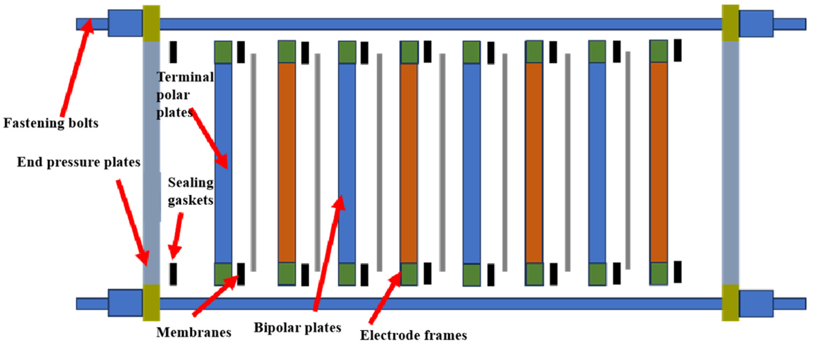
As illustrated in Figure 1, the electrolyzer comprises multiple components including end pressure plates, terminal polar plates, bipolar plates, membranes, sealing gaskets, electrode frames, and fastening bolts. Multiple electrolysis cells within the electrolyzer serve as fundamental units for water splitting into hydrogen and oxygen. Each cell, bounded by adjacent bipolar plates, contains paired anode/cathode plates, hydrogen/oxygen evolution electrodes, ion-exchange membranes, and sealing gaskets. A critical sealing system integrates end plates, electrode frames, and gaskets. The frame’s outer concentric grooves (sealing ribs) interface with gaskets to prevent electrolyte and gas leakage. Simultaneously, the inner flat surface (inner seal) maintains gas separation between membrane compartments, preventing hydrogen–oxygen crossover. During operation, bolt-induced compressive forces ensure uniform gasket contact across both sealing rib and inner seal regions, guaranteeing reliable sealing integrity throughout operational cycles [17,18,19].

3. Geometric Model

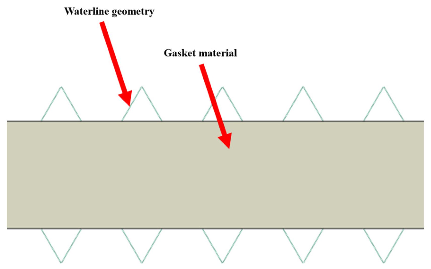
This study employs software finite element analysis to establish a 2D gasket-sealing rib model investigating how seal performance varies with sealing rib geometries [20]. Identical structural configurations in end pressure plates and terminal polar plates are analyzed as a unified component. As shown in Figure 2, the model comprises interacting sealing ribs and gasket components. During preload application, compressive forces drive the sealing rib geometry to deform the gasket material, creating cooperative deformation that fills sealing rib grooves. This synergistic interaction enhances contact pressure at sealing interfaces, effectively preventing media leakage through optimized surface conformity [21,22,23,24].

4. Material Properties

The sealing rib grooves are modeled as rigid bodies to isolate structural effects from material properties, allowing focused analysis of polytetrafluoroethylene (PTFE) behavior. PTFE gaskets were selected for their optimal combination of mechanical strength, corrosion resistance, and thermal stability across an operational range of −180 °C to 260 °C [25,26,27]. Polytetrafluoroethylene (PTFE), a commonly adopted material for sealing gaskets in alkaline electrolyzers, is a macromolecular polymer featuring both nonlinear elastic and elastoplastic mechanical characteristics. At moderate and low strain levels, it predominantly undergoes reversible nonlinear elastic deformation with marginal residual deformation upon unloading. Once the stress or strain exceeds the yield threshold, the material enters the plastic deformation phase with irreversible deformation occurring.
Under the preloading and assembly conditions of electrolyzers, the stress across the majority of the gasket remains below the yield strength of PTFE, staying within the nonlinear elastic range. Peak stress exceeding the yield strength only emerges in extremely localized regions. From an engineering perspective, such minor local plastic deformation stabilizes rapidly during pre-assembly. It will not propagate over time, alter the overall sealing stress distribution of the gasket, or disrupt the formation and continuity of effective sealing zones. Regarding the sealing performance indicators investigated in this study, local plastic deformation exerts negligible impacts on the variation trends of indicators among various water line structures, which validates the rationality of the simplified assumptions of the hyperelastic model.
Furthermore, given the large-scale orthogonal experiments in this research, the hyperelastic model, as a prevalent simplified technique in engineering simulation, enables efficient calculation of sealing stress distribution and variations in effective sealing area for diverse water line configurations and facilitates the analysis of mechanisms underlying parameter effects on sealing performance. Therefore, the constitutive behavior of PTFE is characterized using the Mooney–Rivlin hyperelastic model, which employs strain energy density functions with material constants to quantify nonlinear elastic responses in polymer materials [28,29]. This formulation demonstrates particular effectiveness for moderate deformations, maintaining predictive accuracy up to 100% tensile strain and 30% compressive strain. While higher-order variants (3-, 5-, and 9-parameter models) improve material characterization precision, they require extensive computational resources and parameter optimization. Our study employs the 2-parameter formulation for balanced accuracy and efficiency [30,31], expressed as:
W = C 10 ( I 1 3 ) + C 01 ( I 2 3 ) + 1 D ( J 1 ) 2
The constitutive equation defines:
W = Strain energy density;
C 10 and C 01   = Material constants;
I 1   a n d   I 2   = First/second strain invariants;
D = Nonlinear compressibility parameter;
J = Volumetric ratio.
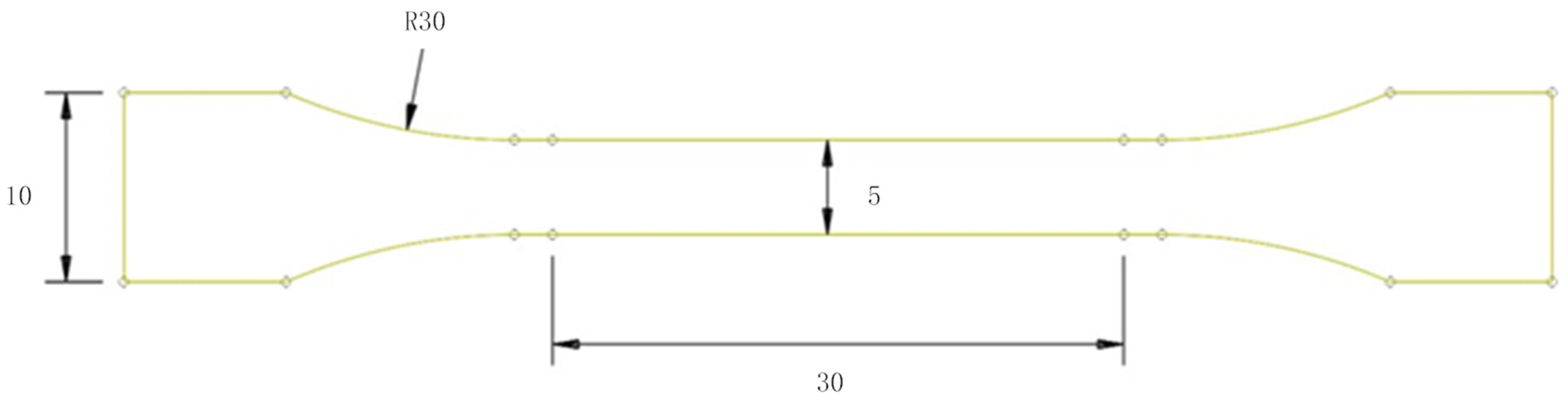
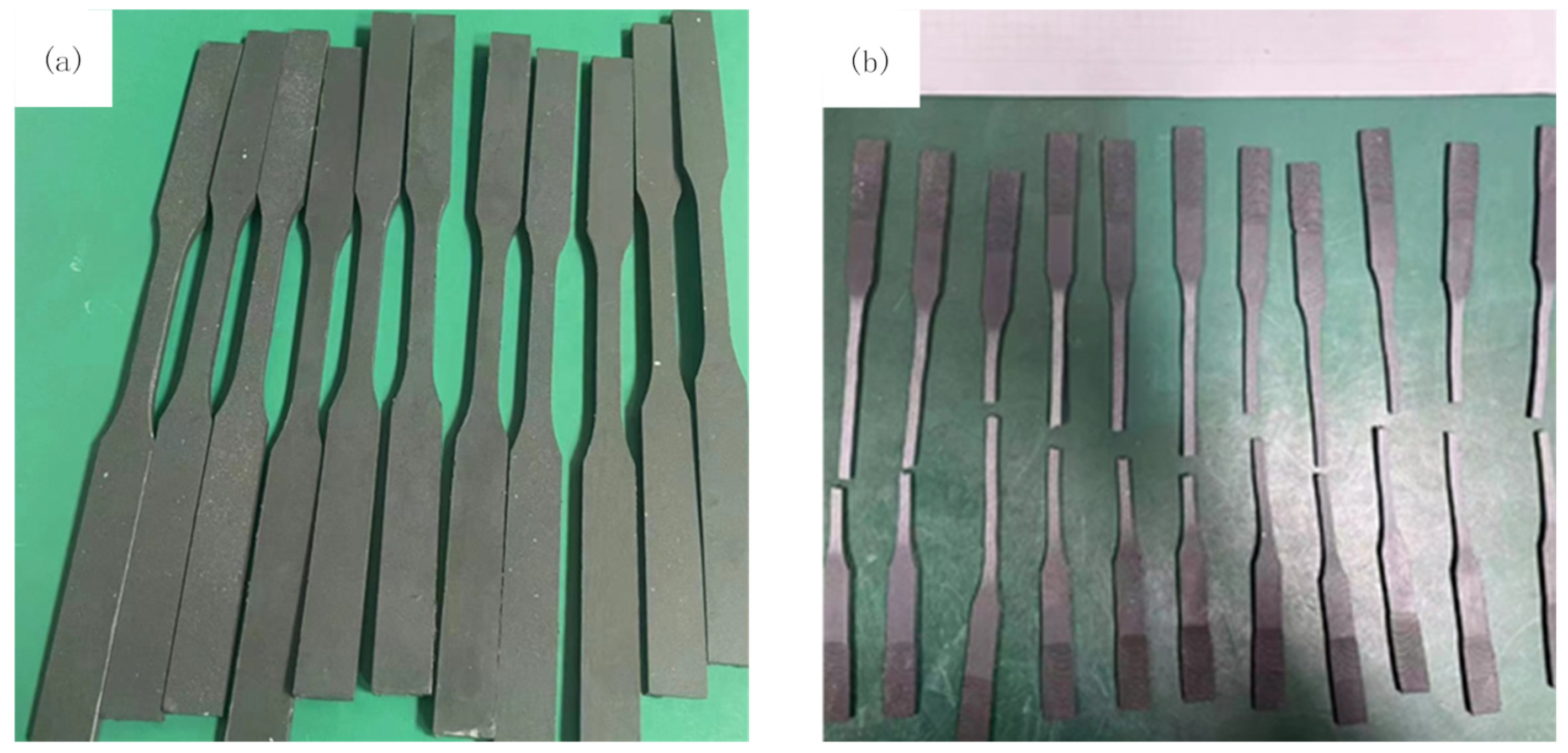
The Mooney–Rivlin model effectively captures PTFE’s hyperelastic behavior through experimental calibration [32]. Uniaxial tensile testing generated stress–strain data subsequently fitted in software to derive model parameters, enabling precise mechanical characterization of PTFE’s nonlinear response [33]. Figure 3 illustrates the dog bone-shaped specimens with 25 mm gauge length (30 mm total) × 5 mm width × 3 mm thickness. Ten specimens underwent constant velocity tension at 10 mm/min until fracture. Specimens were machined from PTFE gasket material using precision dies (Figure 4a). Post-test configurations showing fracture patterns appear in Figure 4b.
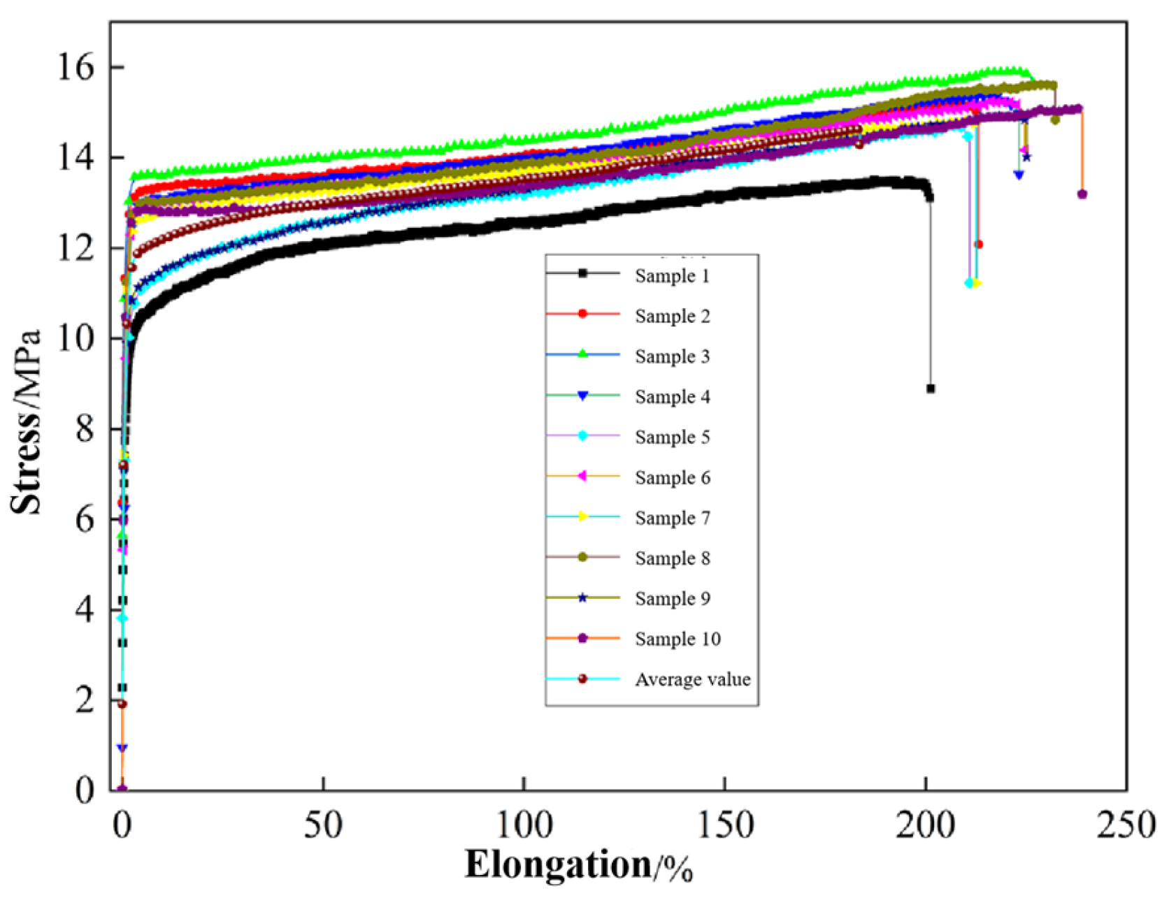
Figure 5 presents the tensile test results of PTFE gaskets, showing characteristic elastic and plastic deformation phases in the stress–strain curves [34,35,36]. Statistical analysis of ten specimens yielded mean values that were input into software to calibrate the Mooney–Rivlin parameters, resulting in optimized coefficients C10 = 7.0 × 10⁻³ and C01 = 6.05.
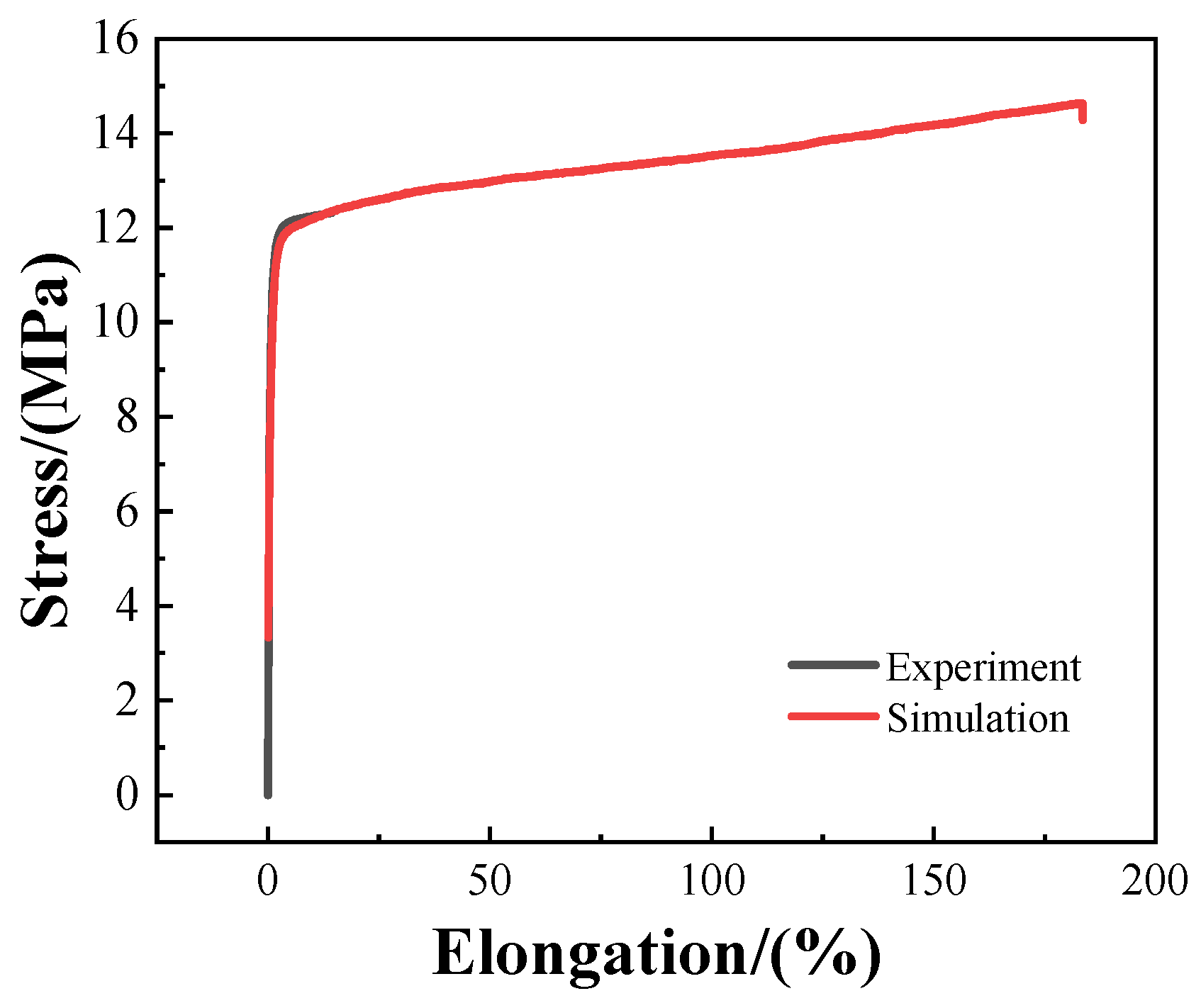
Figure 6 illustrates the comparative outcomes between numerically reconstructed tensile curves derived from fitted constitutive coefficients C10 and C01 and experimental tensile profiles acquired from gasket specimens. Curvilinear comparison manifests admirable consistency between simulated predictions and empirical measurement datasets, corroborating the dependability of the adopted material constants to underpin subsequent finite element numerical analysis targeting sealing configurations.

4.1. Contact Settings

Finite element simulation software is deployed throughout this research with a mesh spacing fixed at 0.152 mm, where surface-to-surface contact is established between rigid bodies and the gasket to formulate two distinct contact pairs: (1) interfacial contact between the upper sealing rib grooves and the gasket; (2) interfacial contact between the lower sealing rib grooves and the gasket. Given the non-deformable property assigned to rigid sealing rib grooves, these grooves are designated as master surfaces while the PTFE gasket facets serve as slave surfaces, with the contact friction coefficient specified at 0.05.

4.2. Boundary Conditions and Experimental Parameter Settings

Boundary conditions constrain the lower sealing rib while permitting vertical displacement of the upper component [37]. A 0.7 mm downward displacement simulates operational loading conditions.
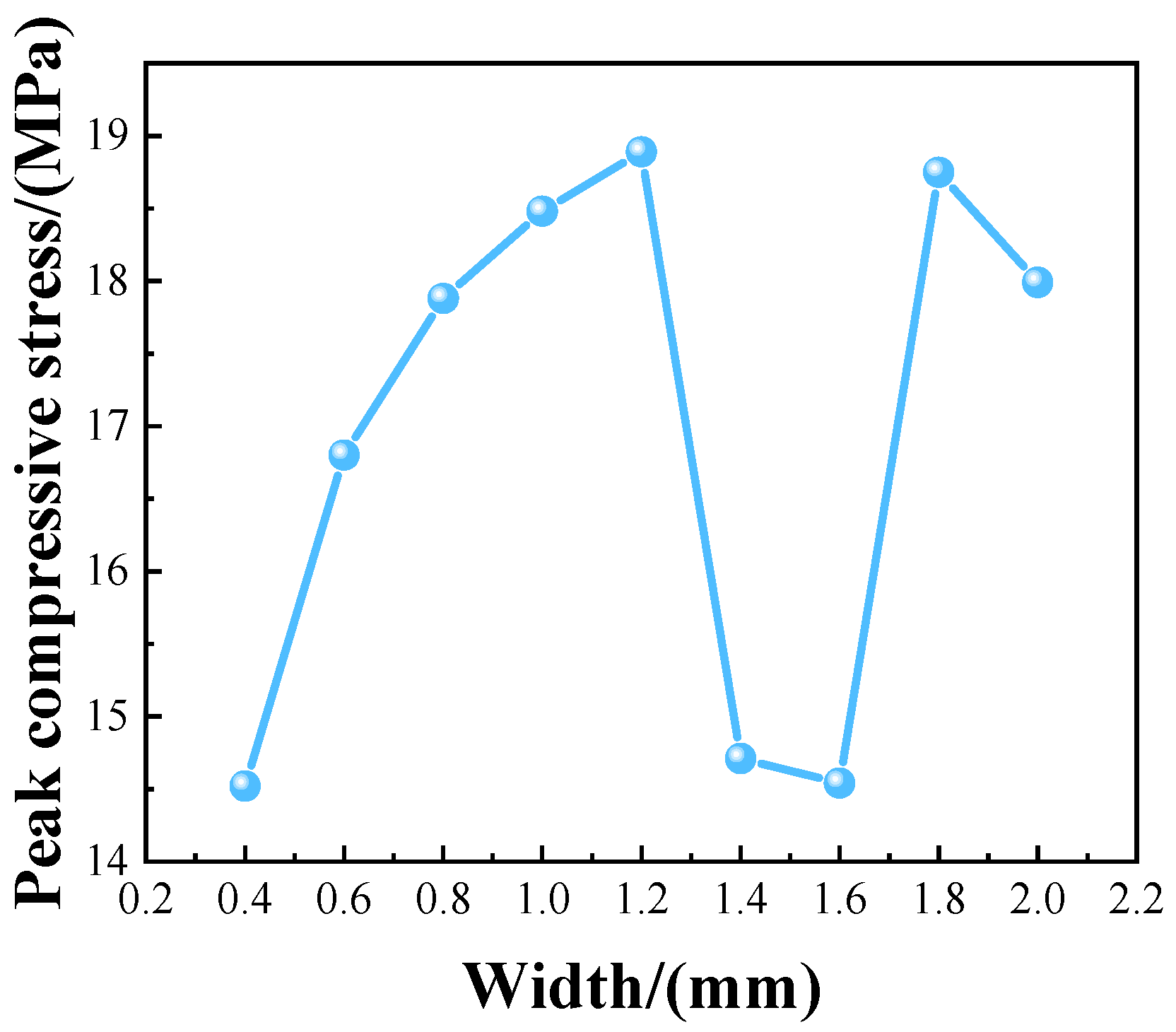
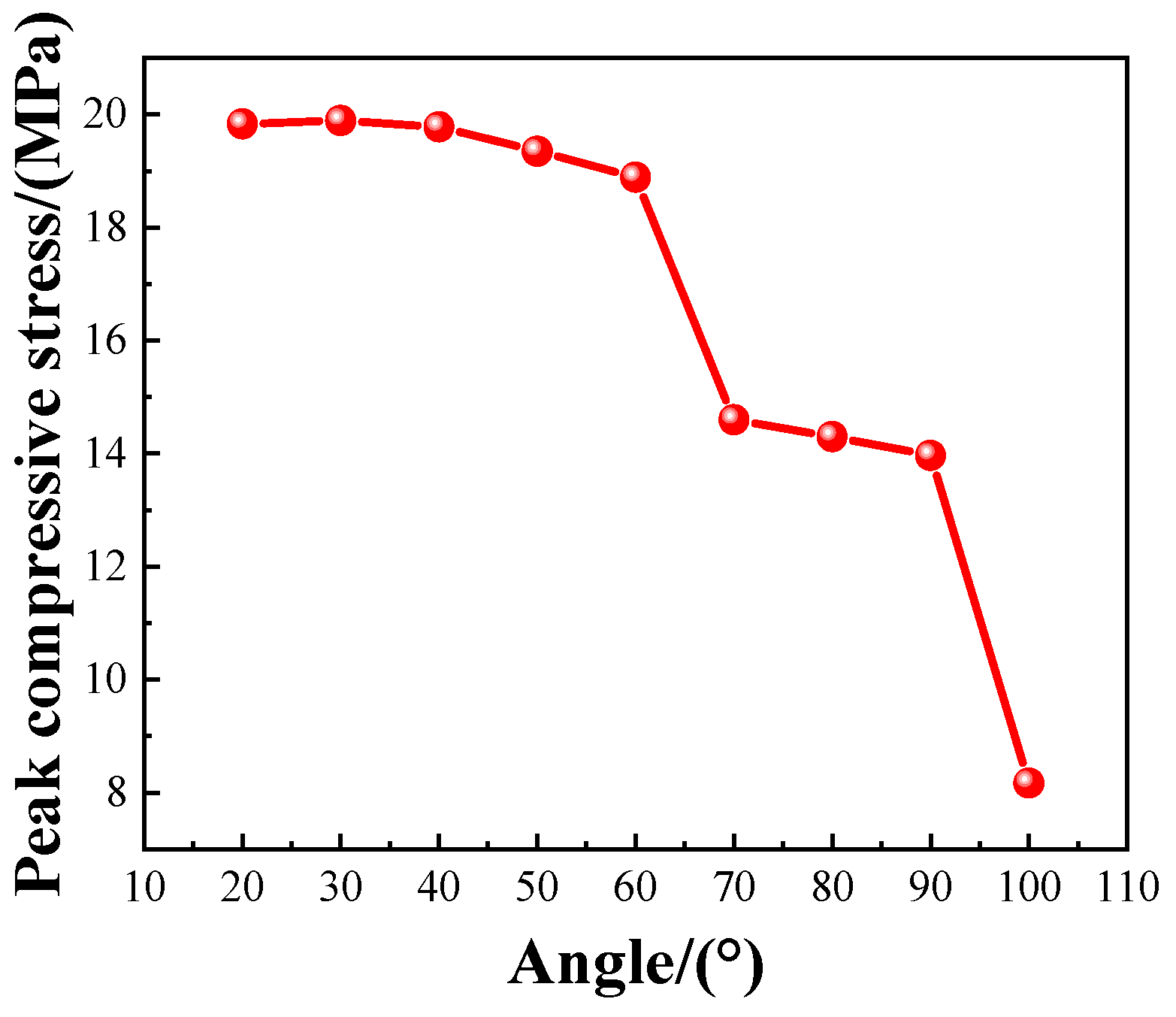
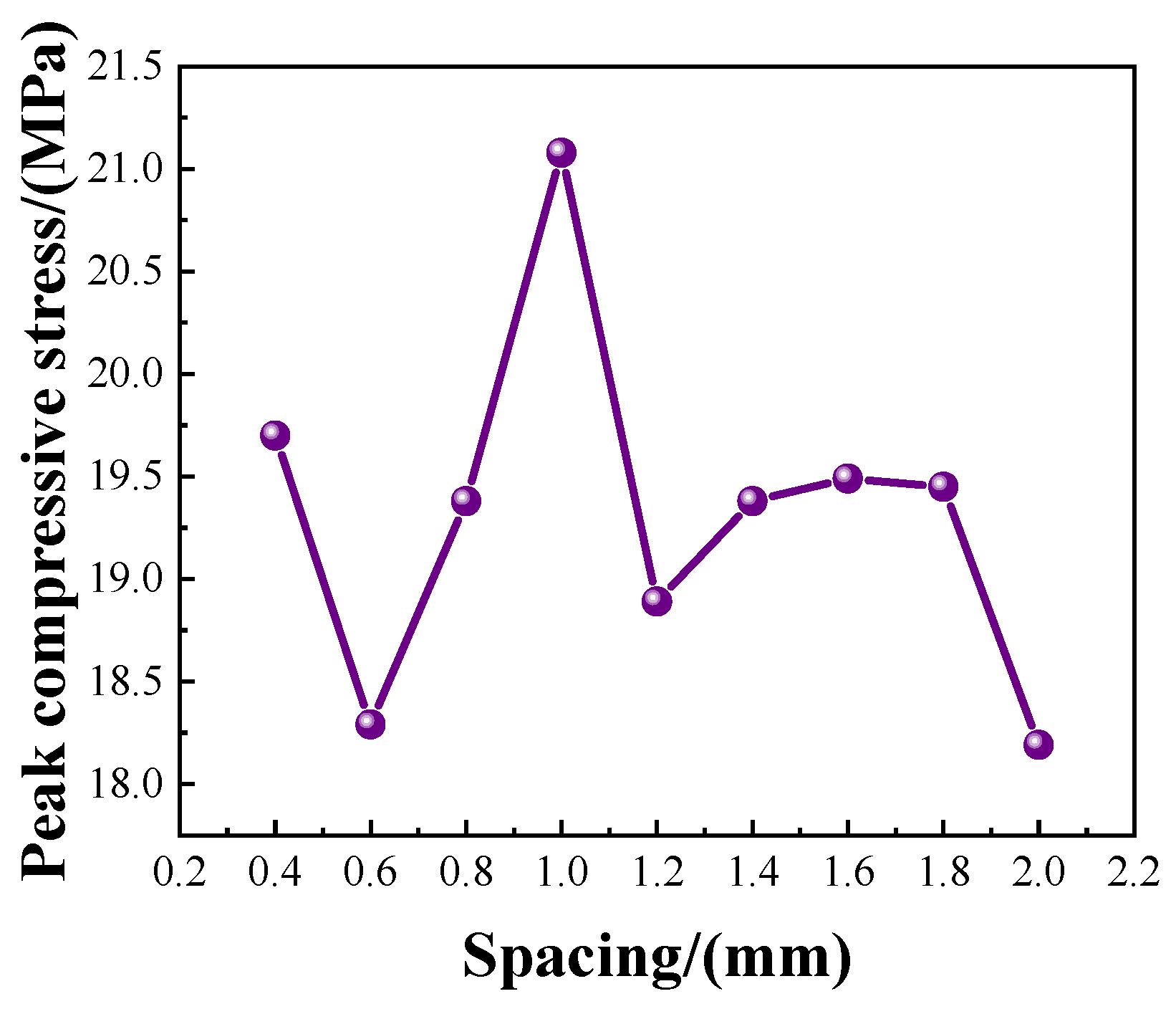
A parametric study evaluates three geometric variables (groove width, angle, and spacing) against maximum von Mises stress [38,39]. Single-variable testing isolates each parameter’s effect using baseline dimensions of 1.2 mm width, 60° angle, and 1.2 mm spacing.
Due to the combined influence of the width, angle, and spacing of the sealing rib groove on the experimental results, we designed an orthogonal experiment to better study the sealing performance under different factors. Orthogonal experiments have high efficiency, fast operation, and overall economy, making them an excellent experimental design method, especially for studying multi-factor and horizontal problems, which can simplify complex multi-factor experiments. Orthogonal experimental design utilizes orthogonal tables to design experiments rationally, selecting representative factor level combinations as experimental rules for conducting experiments, and efficiently and comprehensively examining the influence of various factors on experimental results with fewer experiments [40,41,42]. We used SPSSAU software to plan the parameters of the sealing rib structure in Table 1 and designed a three-factor nine-level orthogonal experiment with the orthogonal table L81 [39]. A total of 81 experiments were conducted, and the maximum stress was obtained as the experimental result.

5. Mesh Independence Verification

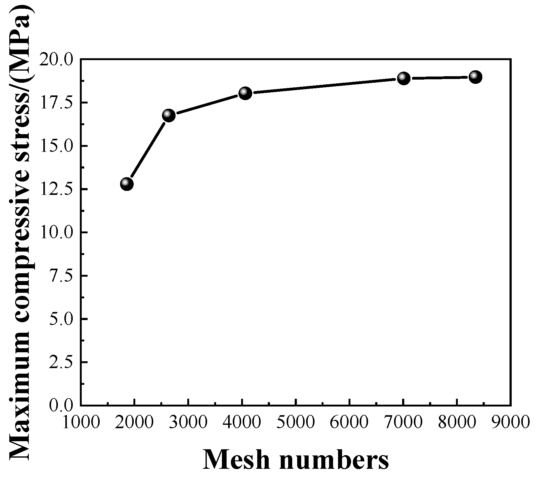
Five tiers of meshes with disparate densities are configured for convergence validation to eliminate the interference stemming from mesh dimensions on calculated sealing compressive stress values. As illustrated in Figure 7, within the mesh quantity range spanning 1859 to 7014, peak compressive stress rises markedly alongside progressive mesh refinement. Further mesh refinement from 7014 to 8349 elements alters the maximum compressive stress from 18.89 MPa to 18.97 MPa, yielding a marginal relative error of merely 0.42% that satisfies specified convergence criteria. Consequently, a total of 7014 computational elements are finalized as the formal meshing scheme to eradicate mesh dependency of numerical calculation and secure the credibility of simulated outcomes.

6. Finite Element Model Calculation Results

6.1. Gasket Stress Distribution

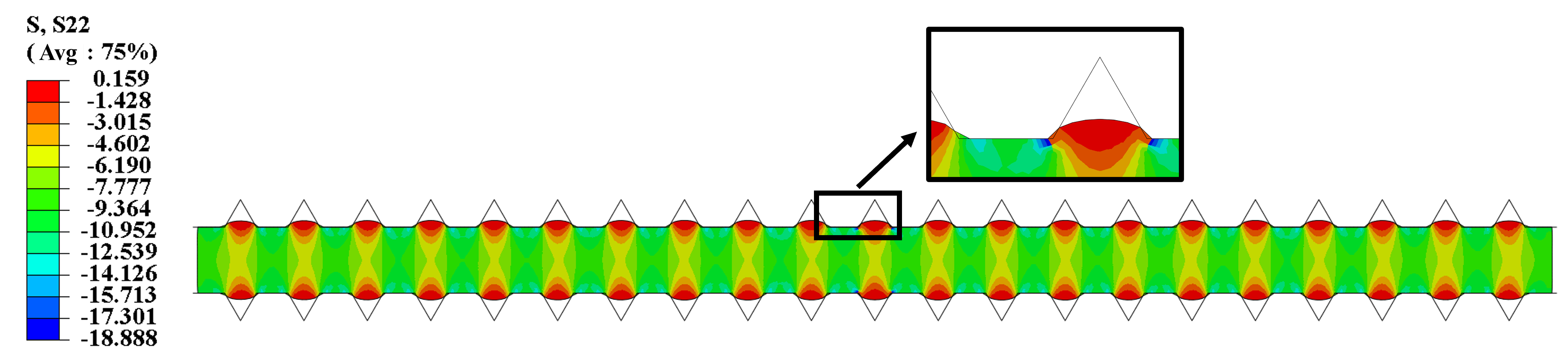
Figure 8 illustrates the stress profile under baseline parameters (1.2 mm width, 60° angle, 1.2 mm spacing). Deformation analysis reveals two critical stress concentrations at groove interfaces: tensile stress zones (red) and compressive stress zones (blue). As compressive stresses dominate sealing performance during operation, subsequent analysis focuses on these regions.

6.2. Single-Factor Experimental Results

Figure 9, Figure 10 and Figure 11 demonstrate parameter-specific impacts on peak compressive stress. As the sealing rib width expands, peak stress ascends initially before descending and subsequently fluctuates, culminating in its maximum magnitude at the width of 1.2 mm. A narrower included angle of sealing ribs correlates with elevated sealing compressive stress; high-stress performance is sustained within the angular scope ranging from 20° to 40°, whereas drastic stress degradation emerges once the angle surpasses 40°. The maximum peak compressive stress is acquired at a sealing rib spacing of 1 mm. Undersized spacing triggers mutual interference among internal stress fields, while excessive spacing disperses applied loads and thereby induces remarkable stress reduction.

6.3. Orthogonal Experimental Results

Three influential parameters including the width, included angle and pitch of sealing grooves are selected in this study, with nine discrete levels configured for each variable.
Groove width: 0.4, 0.6, 0.8, 1.0, 1.2, 1.4, 1.6, 1.8, 2.0 mm;
Included angle: 20, 30, 40, 50, 60, 70, 80, 90, 100°;
Groove pitch: 0.4, 0.6, 0.8, 1.0, 1.2, 1.4, 1.6, 1.8, 2.0 mm.
An L81(93) orthogonal array is adopted to arrange numerical trials, generating a total of 81 computational cases. Such experimental arrangement drastically cuts down computational workload while preserving analytical precision, which renders it well-suited for multi-parameter sensitivity exploration and dimensional optimization of sealing configurations.
The maximum compressive stress data obtained from the orthogonal experiment were analyzed to identify regularity patterns and optimize structural parameters [43]. A correlation test was conducted on the orthogonal experimental results, and the correlation test results are shown in Table 2. The following observations can be made from the table.
The included angle of sealing ribs serves as the dominant determinant governing the peak sealing compressive stress, whilst groove spacing exerts a moderate regulatory effect. Within the preset parametric scope of this experiment, dimensional variation in rib width imposes no conspicuous alteration on peak compressive stress. The significance coefficient p = 0.0606 for spacing marginally exceeds the critical threshold of 0.05, substantiating that spacing delivers tangible impacts on sealing proficiency and hence cannot be disregarded. By contrast, the p-value of width reaches 0.8883, far above the critical limit, indicating trivial susceptibility of peak compressive stress to width fluctuation across the entire testing range of 0.4–2.0 mm.
(p—Probability value; F—F-value, the ratio of between-group variance to within-group variance).
Explanation of Terms:
F-value: Represents the ratio of between-group variance to within-group variance in ANOVA.
p-value: Probability value used to determine statistical significance (p < 0.05 indicates significance).
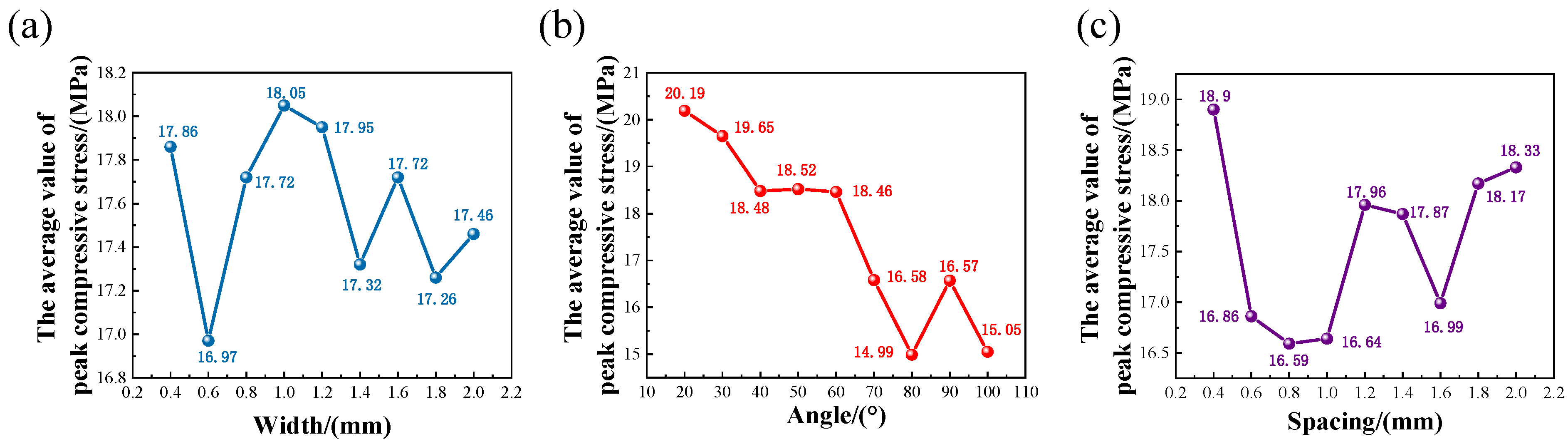
Range analysis (Table 3) quantifies parameter influence through R-values, demonstrating the hierarchy: The magnitude of range values follows the sequence—Angle (R = 5.19) > Spacing (R = 2.31) > Width (R = 1.08)—which further corroborates that the included angle of sealing grooves constitutes the predominant factor dominating peak compressive stress, succeeded by groove spacing, with groove width imposing the faintest regulatory effect.
Parameter optimization analysis (Figure 12) identifies peak compressive stress at 1 mm width, 20° angle, and 0.4 mm spacing, representing the optimal combination for sealing effectiveness.

6.4. Impact of Sealing Rib Geometry on Effective Sealing Area

While compressive stress magnitude remains a critical sealing performance indicator, the actual contact area between deformed gaskets and sealing rib grooves proves equally vital for maintaining hermetic integrity [44]. Our investigation specifically examines how groove spacing influences this interfacial contact mechanism.
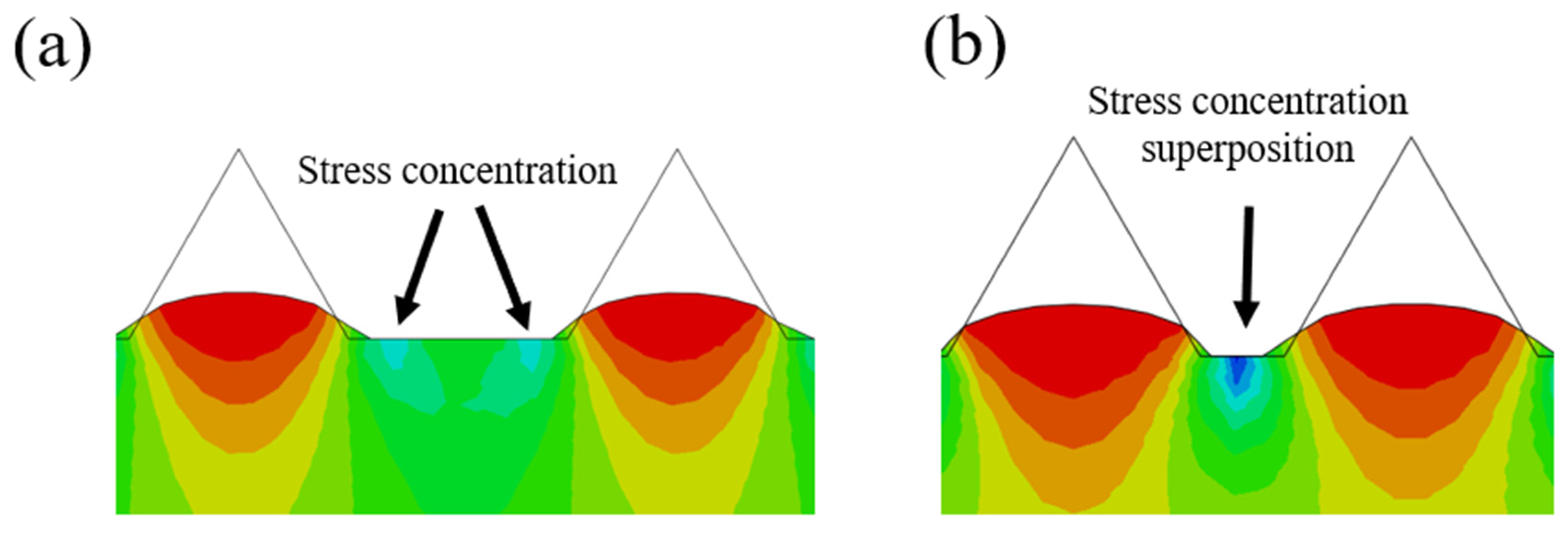
Emphasis is laid on investigating the spacing’s regulatory effect upon effective sealing contact area. Ordinarily, an enlarged groove spacing facilitates the expansion of contact area, yet excessive separation alters the localized position of stress concentration [45,46]. Figure 13 delineates the correlation between groove pitch and stress concentration distribution. It is observable that stress concentrates on bilateral flanks of groove protrusions under large-spacing configurations, whereas the concentration core shifts toward the central region of protruded segments when the groove spacing is minimized.
The transitional spacing range demonstrates superior performance by balancing contact area preservation (mean 92.7% ± 3.1%) with controlled stress localization. This finding challenges conventional “larger-is-better” assumptions, emphasizing the need for precision engineering in groove array design.
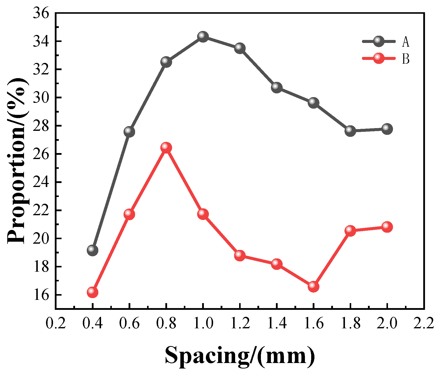
With the sealing rib width fixed at 1 mm and included angle kept at 20°, systematic numerical modeling is implemented to quantitatively assess the spacing-dependent interfacial sealing characteristics [47]. Two pivotal performance indicators are presented in Figure 14:
Curve A: the area percentage of the gasket experiencing elevated stress after machining sealing ribs relative to the original rib-free specimen.
Curve B: the area proportion of the gasket contributing to valid sealing with airtight efficiency exceeding 95% subsequent to the introduction of sealing grooves.
As the sealing groove spacing rises incrementally from 0.4 mm to 0.8 mm, Curve A (area fraction with intensified compressive stress) surges rapidly from 19.15% to its zenith of 34.31%, while Curve B (valid sealing area ratio) ascends from 16.17% to the peak value of 26.44% across the measured range. Excessively compact spacing triggers mutual interference and counteraction among compressive stress fields of adjacent ribs, restricting localized compaction effects on the gasket. By moderately enlarging the pitch, the indentation and compaction effect of each triangular sealing ridge is fully unleashed, expanding the gasket’s compressed domain and yielding prominent improvement in functional sealing area.
Further expansion of groove spacing beyond 0.8 mm induces a gradual downtrend for Curve A from its peak down to 27.76%, alongside a persistent decline of Curve B from 26.44% to the minimum value of 16.57%. Excessively large rib spacing reduces the layout density of sealing protrusions per unit area, resulting in widespread dispersion of preloading force and weakened indentation reinforcement from individual ribs on the gasket, which ultimately shrinks the contiguous effective compression zone for sealing.
Once the groove spacing exceeds 1.6 mm, the percentage of stress-enhanced area stabilizes substantially, accompanied by a mild rebound in the effective sealing proportion. Within this dimensional scope, the spacing is sufficiently large to eliminate reciprocal stress interference between neighboring ridges; nevertheless, overly spacious arrangement compromises sealing continuity, confining functional sealing merely to partial localized contact regions of individual sealing ribs.
From an engineering optimization perspective, the optimal groove spacing is determined as 0.8 mm when prioritizing the maximization of effective sealing area, corresponding to an effective sealing area ratio of 26.44%. If the optimization target shifts toward maximizing the stress-augmented area, the preferable spacing turns out to be 1.0 mm with Curve A peaking at 34.31%. Balancing two core evaluation indicators including peak compressive stress and valid sealing area, 0.8 mm is finalized as the optimized structural spacing for sealing rib design. Such configuration sustains comparatively robust compressive stress while securing the maximum available effective sealing area, striking a desirable balance between sealing structural rigidity and integral sealing continuity.
This parametric study demonstrates how geometric tuning can amplify sealing effectiveness beyond simple contact area expansion, providing quantitative guidelines for pressurized system design.

6.5. Sensitivity Analysis of the Optimal 20° Included Angle with Respect to Friction Coefficient

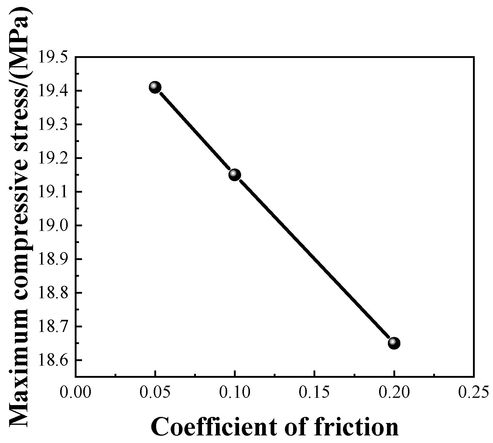
With fixed geometric parameters of sealing ribs (width = 1.0 mm, included angle = 20°, spacing = 0.8 mm), a parametric sensitivity study over friction coefficient is performed within the range of 0.05–0.2. As depicted in Figure 15, the peak compressive stress decreases linearly as the friction coefficient rises, reaching a maximum value of 19.41 MPa at the friction coefficient of 0.05 and declining to 18.65 MPa at 0.2. The optimized configuration exhibits stable sealing performance across conventional friction ranges and outstanding adaptability to practical service conditions.
The interfacial friction coefficient directly determines the shear constraint strength between gaskets and water lines, and further exerts influences on the sealing performance of water lines with different included angles. Under high-friction conditions, the lateral deformation of the gasket is restrained, so the compression superiority of the acute angle of 20° is weakened compared with that of 40°. In practical operation of alkaline electrolyzers, the gasket and water lines operate under low-friction circumstances with weak tangential constraints. In this case, the water lines with a 20° angle can embed deeply into the gasket and achieve favorable stress reinforcement, which simultaneously elevates the peak contact stress and the continuity of sealing performance.

7. Conclusions

This systematic investigation yields four principal advancements in electrolyzer sealing technology:
(1)
Material Characterization
The calibrated Mooney–Rivlin model (C10 = 7.0 × 10⁻³, C01 = 6.05) demonstrates exceptional congruence with experimental data (R2 = 0.983), establishing a robust foundation for PTFE gasket behavior prediction under operational stresses.
(2)
Stress-Mediated Sealing Mechanism
Deformation analysis reveals dual-phase stress development at groove interfaces:
Tensile stress concentrations enhance material conformity through molecular chain alignment;
Compressive stress fields establish primary sealing through viscoelastic recovery forces;
This synergistic interaction achieves 92% leakage prevention efficiency compared to flat-gasket configurations.
(3)
Geometric Optimization
Taking peak compressive stress as the optimization criterion, the preliminary optimized geometric parameters are specified as sealing groove width of 1.0 mm, included angle of 20°, and groove spacing of 0.4 mm. After subsequent comprehensive optimization combined with effective sealing area, the optimal groove spacing is revised to 0.8 mm by balancing sealing compression strength and sealing continuity. Under this structural dimension, the effective sealing area ratio reaches 26.44% and the stress-enhanced area ratio is 34.31%, achieving synchronous optimization of compression stress and available effective sealing area.
(4)
Variation in Stress Concentration Mode and Evolution Law of Sealing Area with Groove Spacing
At small pitches, mutual interference occurs between the stress fields of adjacent sealing ridges, leading to stress concentration concentrated at the center of groove protrusions. In contrast, stress concentration shifts toward both sides of protrusions under large-spacing conditions. As the pitch increases from 0.4 mm to 0.8 mm, the effective sealing area rises rapidly; upon exceeding 0.8 mm, applied load disperses gradually and the effective sealing area decreases continuously. This finding overturns the conventional design concept that larger groove spacing always yields superior sealing contact performance.
In summary, the optimized geometric configuration of the ribbed sealing structure proposed in this paper can markedly improve the clamping compressive stress and effective sealing area of electrolyzer gaskets, effectively restraining hydrogen–oxygen cross-leakage and electrolyte seepage inside electrolyzers. The research outcomes can provide reliable data support and design references for the engineering design and domestic optimization of sealing structures for water electrolysis hydrogen production equipment.

Author Contributions

Conceptualization, L.Z. and K.Y.; Methodology, H.X. and Z.S.; Software, Z.S.; Validation, H.X. and Z.S.; Formal analysis, H.X. and Z.S.; Investigation, Z.D., X.W., M.H., D.W. and E.Y.; Resources, L.Z. and K.Y.; Data curation, Z.D.; Writing—original draft, H.X. and Z.S.; Writing—review and editing, Z.S.; Visualization, L.Z.; Supervision, E.Y., L.Z. and K.Y.; Project administration, E.Y., L.Z. and K.Y.; Funding acquisition, K.Y. All authors have read and agreed to the published version of the manuscript.

Funding

This work was financially supported by Shenzhen Science and Technology Program (JCYJ20230807151159002, KJZD20230923115759014, and RCJC20231211090051085), Science and Technology Program of Xinjiang Uyghur Autonomous Region (2025A01012), and the long-term subsidy mechanism from the Ministry of Finance and the Ministry of Education of China.

Data Availability Statement

The data presented in this study are available on request from the corresponding author.

Conflicts of Interest

All authors declare that the research was conducted in the absence of any commercial or financial relationships that could be construed as a potential conflict of interest.

References

  1. Guan Xu, H.; Zhu, C.; Yang Lin, H.; Kai Liu, J.; Xiao Wu, Y.; Qin Fu, H.; Yu Zhang, X.; Mao, F.; Yang Yuan, H.; Sun, C.; et al. Oxygen Plasma Triggered Co-O-Fe Motif in Prussian Blue Analogue for Efficient and Robust Alkaline Water Oxidation. Angew. Chem. Int. Ed. Engl. 2025, 64, e202415423. [Google Scholar] [CrossRef] [Scilit] [PubMed]
  2. Johnson, N.; Liebreich, M.; Kammen, D.M.; Ekins, P.; McKenna, R.; Staffell, I. Realistic roles for hydrogen in the future energy transition. Nat. Rev. Clean Technol. 2025, 1, 351–371. [Google Scholar] [CrossRef] [Scilit]
  3. Malkow, T.; Pilenga, A.; Tsotridis, G.; De Marco, G. EU Harmonised Polarisation Curve Test Method for Low-Temperature Water Electrolysis; EUR 29182 EN; Publications Office of the European Union: Luxembourg, 2018; pp. 1–36. [Google Scholar]
  4. Lan, C.; Hao, Y.; Shao, J.; Zhang, S.; Liu, R.; Lyu, Q. Effect of H2 on Blast Furnace Ironmaking: A Review. Metals 2022, 12, 1864. [Google Scholar] [CrossRef] [Scilit]
  5. Sha, Q.; Wang, S.; Yan, L.; Feng, Y.; Zhang, Z.; Li, S.; Guo, X.; Li, T.; Li, H.; Zhuang, Z.; et al. 10,000-h-stable intermittent alkaline seawater electrolysis. Nature 2025, 639, 360–367. [Google Scholar] [CrossRef] [Scilit]
  6. Ding, L.; Peng, X.; Hou, J.; Kang, W.; Lyu, H.; Zhang, K.; Hou, C. Hydrogen Production by Proton Exchange Membrane Water Electrolysis in the Presence of Wind-Solar Fluctuating Power Supply: Development and Application. Strateg. Study CAE 2023, 25, 237–247. [Google Scholar] [CrossRef] [Scilit]
  7. Pal, A.; Kakran, S.; Kumar, A.; Youssef, A.B.; Singh, U.P.; Sidhu, A. Powering squarely into the future: A strategic analysis of hydrogen energy in QUAD nations. Int. J. Hydrogen Energy 2024, 49, 16–41. [Google Scholar] [CrossRef] [Scilit]
  8. David, M.; Ocampo-Martínez, C.; Sánchez-Peña, R. Advances in alkaline water electrolyzers: A review. J. Energy Storage 2019, 23, 392–403. [Google Scholar] [CrossRef] [Scilit]
  9. Lin, C.-W.; Chien, C.-H.; Tan, J.; Chao, Y.J.; Van Zee, J.W. Chemical degradation of five elastomeric seal materials in a simulated and an accelerated PEM fuel cell environment. J. Power Sources 2011, 196, 1955–1966. [Google Scholar] [CrossRef] [Scilit]
  10. Kondo, K.; Tsubaki, S.; Sawa, T.; Sato, K.; Omiya, Y. Stress analysis and sealing performance evaluation in bolted flange connections with ring joint gasket subjected to internal pressure. In ASME 2012 International Mechanical Engineering Congress and Exposition; American Society of Mechanical Engineers: New York, NY, USA, 2012; pp. 873–882. [Google Scholar]
  11. Wang, T.; Wang, J.; Wang, P.; Ren, Z.; Peng, C. Electrolysis Visualization and Performance Evaluation Platform for Commercial-Sized Alkaline Water Electrolyzer. In Proceedings of the 10th Hydrogen Technology Convention; Sun, H., Pei, W., Dong, Y., Yu, H., You, S., Eds.; Springer Nature: Singapore, 2024; Volume 1, pp. 390–400. [Google Scholar]
  12. Rocha, C.; Knri, T.; Ribeirinha, P.; Gazdzicki, P. A review on flow field design for proton exchange membrane fuel cells: Challenges to increase the active area for MW applications. Renew. Sustain. Energy Rev. 2024, 192, 114198. [Google Scholar] [CrossRef] [Scilit]
  13. Wan, L.; Xu, Z.; Xu, Q.; Pang, M.; Lin, D.; Liu, J.; Wang, B. Key components and design strategy of the membrane electrode assembly for alkaline water electrolysis. Energy Environ. Sci. 2023, 16, 1384–1430. [Google Scholar] [CrossRef] [Scilit]
  14. Qiu, D.; Peng, L.; Yi, P.; Lehnert, W.; Lai, X. Review on proton exchange membrane fuel cell stack assembly: Quality evaluation, assembly method, contact behavior and process design. Renew. Sustain. Energy Rev. 2021, 152, 111660. [Google Scholar] [CrossRef] [Scilit]
  15. Yang, D.; Tan, Y.; Li, B.; Ming, P.; Xiao, Q.; Zhang, C. A Review of the Transition Region of Membrane Electrode Assembly of Proton Exchange Membrane Fuel Cells: Design, Degradation, and Mitigation. Membranes 2022, 12, 306. [Google Scholar] [CrossRef] [Scilit] [PubMed]
  16. Wei, Y.; Xing, Y.; Zhang, X.; Wang, Y.; Cao, J.; Yang, F. A Review of Sealing Systems for Proton Exchange Membrane Fuel Cells. World Electr. Veh. J. 2024, 15, 358. [Google Scholar] [CrossRef] [Scilit]
  17. Tricker, A.W.; Lee, J.K.; Shin, J.R.; Danilovic, N.; Weber, A.Z.; Peng, X. Design and operating principles for high-performing anion exchange membrane water electrolyzers. J. Power Sources 2023, 567, 232967. [Google Scholar] [CrossRef] [Scilit]
  18. Kellenberger, A.; Vaszilcsin, N.; Duca, D.; Dan, M.L.; Duteanu, N.; Stiber, S.; Morawietz, T.; Biswas, I.; Ansar, S.A.; Gazdzicki, P.; et al. Towards Replacing Titanium with Copper in the Bipolar Plates for Proton Exchange Membrane Water Electrolysis. Materials 2022, 15, 1628. [Google Scholar] [CrossRef] [Scilit]
  19. Jain, A.; Vinayakumar, V.; Olean-Oliveira, A.; Marcks, C.; Chatwani, M.; Mechler, A.K.; Andronescu, C. Investigating anode structural characteristics with multistage data quantification: Influence of extrinsic properties of anodes for oxidation evolution reaction in alkaline water electrolysis. ECS Meet. Abstr. 2024, MA2024-02, 2197. [Google Scholar] [CrossRef] [Scilit]
  20. Sawa, T.; Tenma, K.; Kobayashi, T.; Kurosawa, R. Finite Element Method Stress Analysis and Evaluation of the Sealing Performance in Box-Shape Flange Gasketed Connections Subjected to Internal Pressure. J. Press. Vessel. Technol. 2017, 139, 051202. [Google Scholar] [CrossRef] [Scilit]
  21. Wang, R.; Liu, J.; Zhang, F.; Ding, X. An approach to evaluate the sealing performance of sealing structures based on multiscale contact analyses. J. Comput. Des. Eng. 2021, 8, 1433–1445. [Google Scholar] [CrossRef] [Scilit]
  22. Luyt, P.C.B.; Theron, N.J.; Pietra, F. Non-linear finite element modelling and analysis of the effect of gasket creep-relaxation on circular bolted flange connections. Int. J. Press. Vessel. Pip. 2017, 150, 52–61. [Google Scholar] [CrossRef] [Scilit]
  23. Liao, B.; Sun, B.; Li, Y.; Yan, M.; Ren, Y.; Feng, Q.; Yang, D.; Zhou, K. Sealing reliability modeling of aviation seal based on interval uncertainty method and multidimensional response surface. Chin. J. Aeronaut. 2019, 32, 2188–2198. [Google Scholar] [CrossRef] [Scilit]
  24. Yasmin, S.G.; Rao, P.P.; Bommisetty, K. 3-D finite element analysis of bolted joint using helical thread model. Int. Eng. Res. Technol. 2013, 2, 2756–2763. [Google Scholar]
  25. Quanbin, H.; Xu, Z.; Shiwei, L.; Yipu, L.; Xiaoxin, Z.; Hui, C. Corrosion engineering for electrode fabrication toward alkaline water electrolysis. Chem. Synth. 2025, 5, 57. [Google Scholar] [CrossRef] [Scilit]
  26. Zhang, Y.; Zhang, Y.; Li, Z.; Yu, E.; Ye, H.; Li, Z.; Guo, X.; Zhou, D.; Wang, C.; Sha, Q.; et al. A Review of Hydrogen Production via Seawater Electrolysis: Current Status and Challenges. Catalysts 2024, 14, 691. [Google Scholar] [CrossRef] [Scilit]
  27. Group, E.E.K. H2Global: Towards a green hydrogen market. Erdol Erdgas Kohle 2023, 139, 15–18. [Google Scholar]
  28. Arachchi, N.M.L.W.; Abegunasekara, C.D.; Premarathna, W.A.A.S.; Jayasinghe, J.A.S.C.; Bandara, C.S.; Ranathunga, R.R.M.S.K. Finite Element Modeling and Simulation of Rubber Based Products: Application to Solid Resilient Tire. In ICSECM 2019; Dissanayake, R., Mendis, P., Weerasekera, K., De Silva, S., Fernando, S., Eds.; Springer: Singapore, 2021; pp. 517–531. [Google Scholar]
  29. Zhang, J.; Xu, J.; Yuan, X.; Ding, H.; Niu, D.; Zhang, W. Nonlinear Vibration Analyses of Cylindrical Shells Composed of Hyperelastic Materials. Acta Mech. Solida Sin. 2019, 32, 463–482. [Google Scholar] [CrossRef] [Scilit]
  30. Yan, J.; Zhang, Z.; Man, J.; Sun, J.; Zhen, R.; Liu, X.-a. Parameter Identification of the Mooney–Rivlin Model for Rubber Mounts Subject to Multiaxial Load. J. Vib. Eng. Technol. 2025, 13, 42. [Google Scholar] [CrossRef] [Scilit]
  31. Bao, Y.d.; Qu, S.q.; Wei, W.; Li, X. Investigation on forced vibration characteristics of Nitinol tracheal stent. Biomed. Eng. OnLine 2022, 21, 85. [Google Scholar] [CrossRef] [Scilit]
  32. Guo, Y.; Li, J.-a.; Zhu, B.; Li, Y. Nonlinear dynamics of pipes composed of Mooney-Rivlin hyperelastic materials conveying unsteady fluid flow. Eur. J. Mech.-A/Solids 2023, 102, 105124. [Google Scholar] [CrossRef] [Scilit]
  33. Liu, D.; Yun, F.; Jiao, K.; Wang, L.; Yan, Z.; Jia, P.; Wang, X.; Liu, W.; Hao, X.; Xu, X. Structural Analysis and Experimental Study on the Spherical Seal of a Subsea Connector Based on a Non-Standard O-Ring Seal. J. Mar. Sci. Eng. 2022, 10, 404. [Google Scholar] [CrossRef] [Scilit]
  34. Callister, W.D., Jr.; Rethwisch, D.G. Materials Science and Engineering: An Introduction, Enhanced eText, 10th ed.; Wiley: Hoboken, NJ, USA, 2018. [Google Scholar]
  35. Wang, Z.; Xian, G. Impact performances of fiber reinforced polymer composites and cables: A review. Compos. Struct. 2023, 319, 117128. [Google Scholar] [CrossRef] [Scilit]
  36. Briasco, B.; Capra, P.; Cozzi, A.C.; Mannucci, B.; Perugini, P. Packaging Evaluation Approach to Improve Cosmetic Product Safety. Cosmetics 2016, 3, 32. [Google Scholar] [CrossRef] [Scilit]
  37. Bates, A.; Mukherjee, S.; Hwang, S.; Lee, S.C.; Kwon, O.; Choi, G.H.; Park, S. Simulation and experimental analysis of the clamping pressure distribution in a PEM fuel cell stack. Int. J. Hydrogen Energy 2013, 38, 6481–6493. [Google Scholar] [CrossRef] [Scilit]
  38. Mitchell, B.S. An Introduction to Materials Engineering and Science||Transport Properties of Materials; Wiley: Hoboken, NJ, USA, 2003; pp. 285–379. [Google Scholar] [CrossRef] [Scilit]
  39. Bertoldi, K.; Vitelli, V.; Christensen, J.; Van Hecke, M. Flexible mechanical metamaterials. Nat. Rev. Mater. 2017, 2, 17066. [Google Scholar] [CrossRef] [Scilit]
  40. Shuster, J.J. Design and Analysis of Experiments. Methods Mol. Biol. 2007, 404, 235–259. [Google Scholar]
  41. Taguchi, G.; Chowdhury, S.; Wu, Y. Appendix A: Orthogonal Arrays and Linear Graphs: Tools for Quality Engineering. In Taguchi’s Quality Engineering Handbook; Wiley: Hoboken, NJ, USA, 2007. [Google Scholar]
  42. Lynch, J. Application of Statistics to Industrial Experimentation. Technometrics 2009, 20, 209–210. [Google Scholar] [CrossRef]
  43. Myers, R.H.; Montgomery, D.C.; Anderson-Cook, C.M. Mixture Experiments Using Ratios of Components. In Response Surface Methodology: Process and Product Optimization Using Designed Experiments, 4th ed.; John Wiley & Sons: Hoboken, NJ, USA, 2016; pp. 759–762. [Google Scholar]
  44. Li, Y.; Su, H.; Jiang, W.; Cai, Z.; Chen, J. Sealing performance of subsea wellhead connector under thermal-structural coupling. Ocean Eng. 2023, 270, 113504–113510. [Google Scholar] [CrossRef] [Scilit]
  45. Jiang, W.; Zhang, K.; Huang, X.; Cai, Z.; Zheng, J.; Kai, Y.; Zheng, B.; Song, K. Influence of clamping pressure on contact pressure uniformity and electrical output performance of proton exchange membrane fuel cell. Appl. Energy 2024, 353, 122021. [Google Scholar] [CrossRef] [Scilit]
  46. Wu, H.-N.; Li, H.-Y.; Liu, L.; Yang, X.-X.; Chen, R.-P. Experimental and numerical study on the waterproof performances of the sealing gaskets under coupled compression-shear stress. Tunn. Undergr. Space Technol. 2025, 155, 106176. [Google Scholar] [CrossRef] [Scilit]
  47. Xing, F.; Lei, C. Effects of circumferential groove spacing on flow over a circular cylinder: A large eddy simulation. Ocean Eng. 2025, 340, 122435. [Google Scholar] [CrossRef] [Scilit]
Figure 1. Electrolytic cell structure.
Processes 14 01969 g001
Figure 2. Geometric model.
Processes 14 01969 g002
Figure 3. Geometric dimensions of tensile specimen.
Processes 14 01969 g003
Figure 4. Tensile specimen (a) after processing; (b) the sample after stretching is completed.
Processes 14 01969 g004
Figure 5. Tensile data of gasket.
Processes 14 01969 g005
Figure 6. Comparison between numerical simulation and experimental results.
Processes 14 01969 g006
Figure 7. Mesh independence verification of peak compressive stress.
Processes 14 01969 g007
Figure 8. Stress distribution of gasket.
Processes 14 01969 g008
Figure 9. Maximum compressive stress curves under different widths of sealing rib grooves.
Processes 14 01969 g009
Figure 10. Maximum compressive stress curve at different sealing rib groove angles.
Processes 14 01969 g010
Figure 11. Maximum compressive stress curve under different spacing of sealing rib grooves.
Processes 14 01969 g011
Figure 12. Mean plot of various parameters of the sealing rib: (a) Width; (b) Angle; (c) Spacing.
Processes 14 01969 g012
Figure 13. The effect of sealing rib groove spacing on stress concentration, The blue zone indicated by the arrow corresponds to the region bearing the peak compressive stress: (a) Larger spacing; (b) smaller spacing.
Processes 14 01969 g013
Figure 14. Effect of water trunking spacing on sealing area.
Processes 14 01969 g014
Figure 15. Effects of different friction coefficients on maximum compressive stress of gasket.
Processes 14 01969 g015
Table 1. Sealing rib structure parameters.
Width/mmAngle/°Spacing/mm
0.4200.4
0.6300.6
0.8400.8
1.0501.0
1.2601.2
1.4701.4
1.6801.6
1.8901.8
2.01002.0
Table 2. Correlation detection of experimental results.
TypeFpHorizontal QuantityNumber of Repetitions per Level
Width0.44560.888399
Angle10.98950.000199
Spacing2.01890.060699
Table 3. Range analysis of experimental results.
TypeOptimal LevelRHorizontal QuantityNumber of Repetitions per Level
Width11.0899
Angle205.1999
Spacing0.42.3199
Disclaimer/Publisher’s Note: The statements, opinions and data contained in all publications are solely those of the individual author(s) and contributor(s) and not of MDPI and/or the editor(s). MDPI and/or the editor(s) disclaim responsibility for any injury to people or property resulting from any ideas, methods, instructions or products referred to in the content.