Article

A Novel, Single-Step 3D-Printed Shadow Mask Fabrication Method for TFTs

by
Kelsea A. Yarbrough
1,
Makhes K. Behera
2,
Sangram K. Pradhan
1,3,* and
Messaoud Bahoura
1,4
1
Center for Materials Research, Norfolk State University, Norfolk, VA 23504, USA
2
Virginia Alliance for Semiconductor Technology, Arlington, VA 22201, USA
3
Department of Physics, Norfolk State University, Norfolk, VA 23504, USA
4
Engineering Department, Norfolk State University, Norfolk, VA 23504, USA
*
Author to whom correspondence should be addressed.
Processes 2025, 13(9), 2976; https://doi.org/10.3390/pr13092976
Submission received: 12 August 2025 / Revised: 13 September 2025 / Accepted: 15 September 2025 / Published: 18 September 2025
(This article belongs to the Special Issue Advanced Functionally Graded Materials)

Abstract

This work presents a low-cost and scalable method for fabricating thin-film transistors (TFTs) using a single-step, 3D-printed shadow mask approach. Room temperature growth of both aluminum-doped zinc oxide (AZO) thin film was used as the semiconductor channel, and zirconium oxide (ZrO2) as the high-k dielectric, and the films were never exposed to any post-annealing treatment. Structural and morphological characterization confirmed smooth, compact films with stable dielectric behavior. Electrical measurements revealed a field-effect mobility of 13.1 cm2/V·s, a threshold voltage of ~4.1 V, and an on/off ratio of ~104, validating effective gate modulation and drain current saturation. The off-state current, estimated from AZO conductivity measurements, was ~10−10 A, while the on-state current reached ~10−6 A. Benchmarking against state-of-the-art devices shows that these transistors rival ALD-processed IGZO TFTs and significantly outperform reported indium-free ZnO/AZO devices, while avoiding scarce indium and costly high-temperature or photolithographic processing. These findings establish 3D-printed shadow masks as a practical alternative to conventional lithography for oxide TFT fabrication. The method offers high device performance with simplified, indium-free, and room-temperature processing, underscoring its potential for scalable, transparent, and flexible electronics.

1. Introduction

Thin-film transistors (TFTs) have played a pivotal role in advancing display and sensing technologies for more than six decades due to their high resolution, low power consumption, and scalability on both rigid and flexible substrates [1,2,3,4,5,6,7,8,9,10]. They are now integral to a broad spectrum of electronic and photonic devices, with ongoing improvements in electrical performance, material selection, and process optimization driving rapid technological progress [11,12,13,14,15,16,17,18]. Among candidate semiconductors, zinc oxide (ZnO) and its doped derivatives have attracted significant attention for applications in light-emitting diodes [19,20], solar cells [21,22], photodetectors [23,24], gas sensing [25,26], and TFTs [27,28], owing to their favorable electrical and optical properties [29,30]. The introduction of indium gallium zinc oxide (IGZO) further accelerated TFT development, with the pioneering work of Nomura in 2004 [31] leading to its adoption in commercial flat-panel displays by 2012. IGZO-TFTs gained popularity because of their high electron mobility, optical transparency, and compatibility with low-temperature processing, enabling integration into consumer products by major manufacturers such as Apple, Sharp, LG, and Samsung.
Despite these advantages, IGZO technology faces two major challenges: material sustainability and device reliability. Indium, a critical component of IGZO, is a scarce element with a crustal abundance of only ~0.25 ppm, and more than half of global production is consumed by the flat-panel display industry [32]. This dependence raises concerns about long-term cost stability and resource availability. Additionally, indium-based semiconductors suffer from threshold voltage instabilities under prolonged gate bias and illumination, known as negative-bias illumination stress (NBIS), which degrade long-term device performance [33,34,35,36,37]. These challenges have motivated the search for more sustainable oxide semiconductors and alternative fabrication strategies that can balance cost, scalability, and reliability.
In parallel, additive manufacturing has emerged as a transformative approach for electronics fabrication, offering rapid prototyping, cost-effective production, and scalable manufacturing [38]. In particular, 3D-printed shadow masks are gaining attention as a means of achieving patterned thin-film deposition without the complexity of conventional photolithography. Traditional shadow masks, typically fabricated from thin metal foils or electroformed nickel, have been widely used in combination with vacuum deposition techniques because they are reusable and minimize contamination. However, these masks face several well-documented limitations. The unavoidable mask–substrate gap produces the penumbra effect, resulting in blurred edges and halo deposition that distort intended geometries [39]. Alignment challenges further complicate their use in multilayer or large-area devices, where even small tilts reduce overlay accuracy [40]. In addition, metal masks are prone to thermal expansion, clogging, and redeposition during repeated use, all of which degrade fidelity [41,42]. Complex geometries and fine-pitch patterns remain difficult to achieve and often require costly processes such as laser micromachining or electroforming [43]. These constraints, combined with the high cost and long lead times for custom designs, limit their practicality for iterative device development.
The single-step, 3D-printed shadow mask method presented in this work directly addresses these limitations. By generating masks from CAD designs and fabricating them on demand with consumer-grade 3D printers, this approach enables rapid, low-cost, and flexible prototyping. Complex geometries that are expensive or infeasible with traditional masks, such as interdigitated or non-linear structures, can be readily realized. Importantly, 3D printing eliminates the need for photoresists and wet chemical processing, thereby reducing contamination risks and improving device reliability [44]. The masks can be designed with increased thickness and built-in registration features, which minimize thermal distortion and improve substrate contact to reduce the penumbra effect [45]. Further, direct printing of polymer masks onto substrates has been demonstrated as a means to completely eliminate the mask–substrate gap [46], underscoring the versatility of this approach.
Nevertheless, the resolution and scaling limits of 3D-printed shadow masks must be carefully considered. The resolution of fused deposition modeling (FDM)-based masks, such as those fabricated with acrylonitrile butadiene styrene (ABS) on Ultimaker systems, is inherently constrained by the printer nozzle diameter (typically ~0.4 mm) and layer height, restricting feature fidelity to the hundreds of micrometers range [39]. This is sufficient for TFT channel dimensions (tens to hundreds of micrometers), but it falls short of the finer patterns achievable by electroformed metal masks (~tens of micrometers) or silicon-based masks, which can reach the sub-micron regime (~100–500 nm) [47]. Advanced 3D printing techniques, such as multijet photopolymer printing (MJP), can improve fidelity but remain limited to millimeter-scale features, as thinner masks are prone to deformation during handling and deposition [48]. At the other end of the spectrum, high-end microfabrication techniques such as two-photon polymerization (TPP) can achieve nanoscale resolution (~100 nm) [49,50], but they are not directly compatible with polymer shadow mask fabrication for vacuum deposition. A comparison of conventional and emerging shadow mask fabrication methods is summarized in Table 1.
These comparisons illustrate that while current FDM-based 3D-printed masks are not suitable for sub-micron channel lengths, they provide a powerful balance of cost, speed, and functionality for micro-scale TFT fabrication. Furthermore, their scalability for large-area arrays is practical, as masks can be easily modified in CAD and reprinted on demand, although alignment and flatness remain challenges at wafer scale [51]. In this context, 3D-printed shadow masks represent a cost-effective and versatile solution for rapid prototyping and iterative device development, while sub-micron applications may require alternative fabrication strategies.
The applicability of this method to flexible electronics is equally compelling. Previous studies have demonstrated the use of 3D-printed shadow masks for patterning nanocomposite sensors directly onto flexible, ultra-thin polymer substrates—specifically, ink-deposited MWNTs/PDMS nanocomposites on 25 µm-thick PET—in a single step, enabling the fabrication of large-area flexible pressure sensor arrays with multiplexed formats [40]. Additionally, the polymer-based construction of 3D-printed masks allows them to conform easily to curved or pliable substrates, reducing mechanical stress and misalignment risk compared to rigid metal foils. Because the process avoids resist-based photolithography and wet chemistry, it also remains compatible with heat- or solvent-sensitive flexible substrates. Combined with the rapid design-to-fabrication workflow, these attributes position the method as a highly adaptable, cost-effective solution for large-area and flexible electronics manufacturing.
In this study, we demonstrate the fabrication of indium-free TFTs using a single-step, 3D-printed shadow mask technique. The devices employ aluminum-doped zinc oxide (AZO) as the active channel material, zirconium oxide (ZrO2) as the high-k gate dielectric, and titanium as the bottom contact electrode. Deposition conditions were optimized for each layer, and the resulting devices were comprehensively characterized in terms of their structural, optical, and electrical performance. This work highlights a cost-effective and scalable pathway toward indium-free TFT technology.

2. Experiment/Methods

2.1. Materials Deposition

All deposition steps were conducted at room temperature. Substrates were cleaned by sequential immersion in acetone and isopropyl alcohol for 10 min each to remove surface contaminants. The aluminum-doped zinc oxide (AZO, Jefferson Hills, PA, USA) semiconductor channel layer, approximately 45 nm thick from Kurt J. Lesker made target, was deposited using radio frequency (RF) sputtering. A ZnO:Al (98:2 wt%) ceramic target was used with a Kurt J. Lesker Lab18 sputtering system operated at 150 watts RF power.
The high-k gate dielectric layer, zirconium oxide (ZrO2, Jefferson Hills, PA, USA), and the source/drain contacts, composed of titanium (Ti), were deposited using electron beam evaporation. The ZrO2 and Ti source materials were purchased from Kurt J. Lesker. The thicknesses of the ZrO2 and Ti layers were 80 nm and 150 nm, respectively.
Film thicknesses were verified using a DektakXT profilometer (Bruker, Billerica, MA, USA). In tapping mode, surface morphology was analyzed via atomic force microscopy (AFM) (Veeco Dimension Icon). The electrical performance of the fabricated devices, including current–voltage (I–V), drain current–drain voltage (IDS–VDS), and capacitance–voltage (C–V) characteristics, was evaluated using a Keithley 4200 semiconductor parameter analyzer (make-Keithley, model-4200) and Signatone 1160 Probe Station (make-Signatone, model-1160). Ultraviolet-visible (UV–Vis) spectroscopy was performed using a Perkin Elmer Lambda 950 Spectrometer (make-Perkin Elmer, model-Lambda 950) to assess the optical transmittance of the deposited films.

2.2. Shadow Mask Development

Shadow masks for the AZO channel layer, ZrO2 dielectric layer, and Ti bottom contacts were fabricated using acrylonitrile butadiene styrene (ABS) via an Ultimaker S3 3D printer (Zaltbommel, The Netherlands). ABS was selected over other 3D printing materials (e.g., PLA, nylon, polyvinyl alcohol) for its superior thermal and impact resistance, ensuring durability and dimensional stability during deposition processes.
Mask geometries were designed using AutoCAD, 24.2 software, which enabled precise dimensioning, alignment, and iterative refinement. Finalized designs were exported in standard tessellation language (STL) format, which represents the surface geometry as a mesh of interconnected triangles suitable for 3D printing. The printer software (Ultimaker Cura) then sliced these STL files to fabricate the corresponding shadow masks. Figure 1 shows the STL models of the three shadow masks used for semiconductor channel, dielectric, and contact patterning. The thickness and the resolution of our masks are about 700 μm, limited by the printer nozzle diameter.

3. Device Fabrication

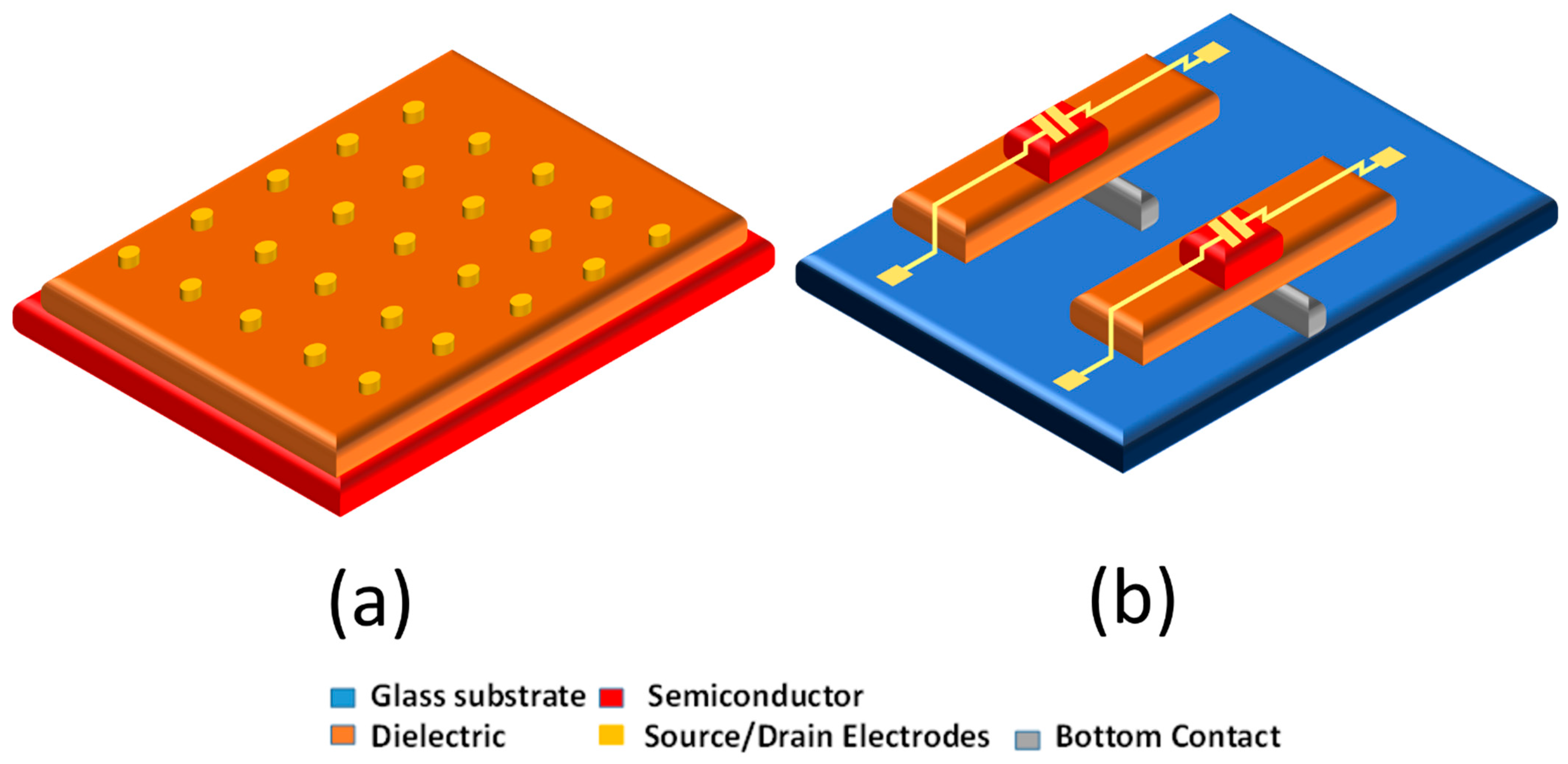
Figure 2a shows the schematic of the fabricated metal–oxide–semiconductor capacitor (MOSCAP), designed to evaluate the dielectric and electrical properties of ZrO2 for potential integration into thin-film transistor (TFT) devices. The ZrO2 dielectric layer was deposited on silicon substrates via electron beam evaporation. Platinum (Pt) top electrodes, 50 nm thick and 200 µm in diameter, were deposited through a shadow mask using DC sputtering. Following electrode deposition, the samples were annealed on a hotplate at 150 °C for 20 min to improve the interfacial contact between the Pt and ZrO2 layers.
TFT devices were fabricated on glass substrates using 3D-printed shadow masks for each layer. First, the bottom metal contacts were deposited onto the substrate through the bottom contact mask. Next, the high-k ZrO2 dielectric layer was deposited using a corresponding dielectric mask. The aluminum-doped zinc oxide (AZO) active channel layer was then deposited via RF sputtering through the channel mask. Finally, the source and drain electrodes were patterned using the top-contact mask aligned over the AZO layer.
The completed TFT devices had a channel width of 30 µm. Figure 2b illustrates the schematic layout of the final TFT structure.

4. Results and Discussion

4.1. ZrO2 Dielectric Characterization

The dielectric layer is critical in insulating device terminals and preventing leakage currents, directly impacting performance and reliability. In this study, zirconium dioxide (ZrO2) was selected as a high-k dielectric due to its favorable properties, including a high dielectric constant (~24) compared to conventional SiO2 (~4). High-k materials enable device miniaturization by allowing thinner insulating layers without increasing leakage currents or power consumption, as the dielectric’s leakage current and gate efficiency are crucial for device performance [52].
Atomic force microscopy (AFM) was employed to characterize the surface morphology of the ZrO2 film deposited via electron beam evaporation at room temperature. The analysis was performed in tapping mode with a resolution of 512 × 512 pixels and a scan rate of 0.5 Hz. The resulting surface exhibited a root mean square (RMS) roughness of 2.27 nm and an average grain size of 75.71 nm (Figure 3a). These values are consistent with literature reports indicating that higher deposition rates tend to increase surface roughness in ZrO2 thin films [53,54].
X-ray diffraction (XRD) analysis confirmed the crystalline structure of the film. A distinct diffraction peak at 2θ = 61° corresponds to the monoclinic phase of ZrO2, which is typically observed in room-temperature-deposited films (Figure 3b) [55]. This phase is known for its thermal stability and suitability in gate dielectric applications. However, the diffraction peak at 2θ = 33 degrees corresponds to the Si substrate peak.
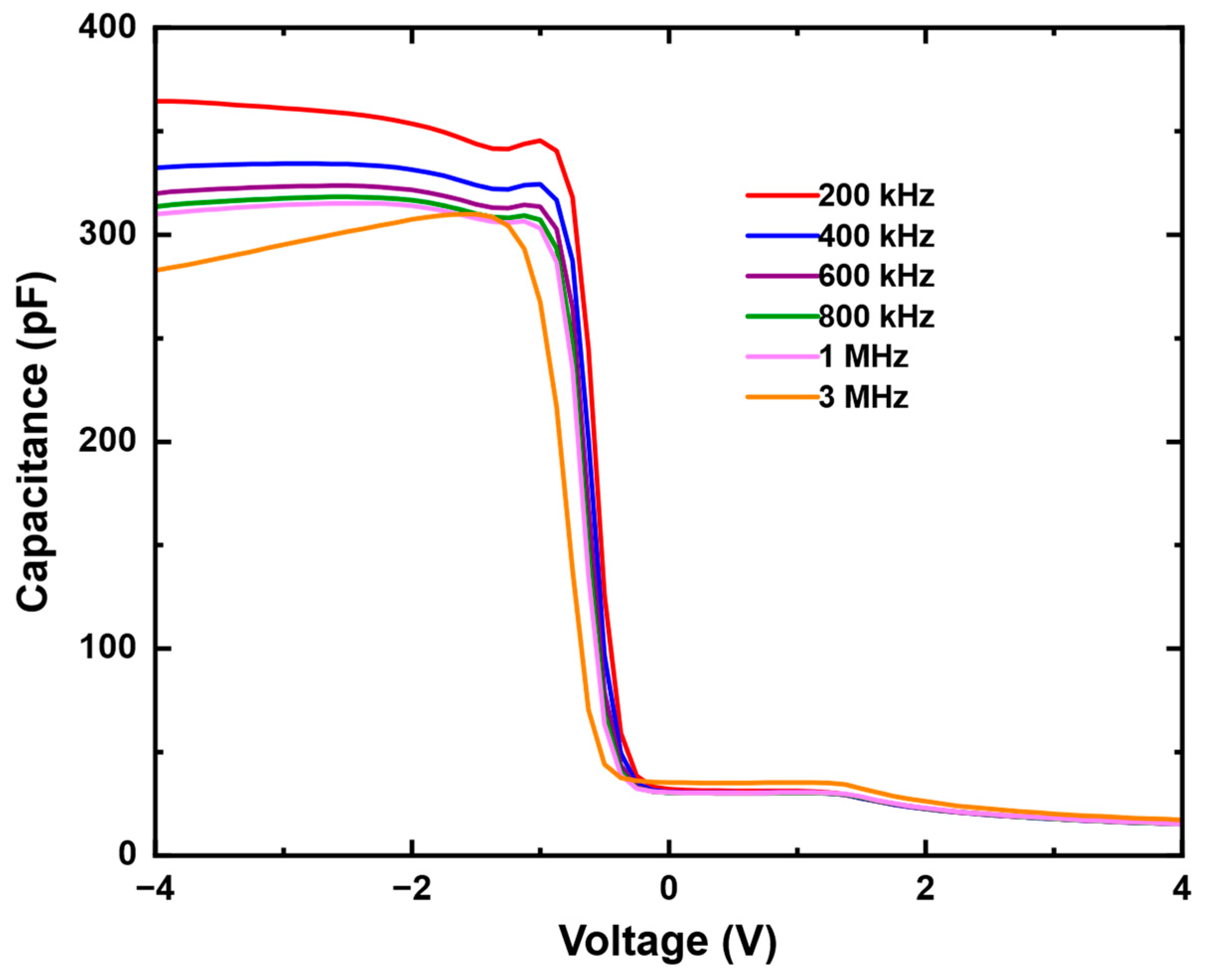
To assess electrical performance, the ZrO2 film was integrated into a metal-oxide-semiconductor capacitor (MOSCAP) structure (Figure 2a), and capacitance–voltage (C–V) measurements were conducted across a range of frequencies. A small variation in capacitance values across different voltage regions was observed, indicating potential challenges in dielectric charge alignment. These fluctuations suggest the presence of minor impurity levels or interface traps within the dielectric film.
Figure 4 displays the frequency-dependent C–V response. As the frequency increased from 200 kHz to 3 MHz, the accumulation capacitance decreased from 364 pF to 282 pF, demonstrating mild frequency dispersion. The characteristic regimes of accumulation, depletion, and inversion were distinguishable, affirming the functionality of the dielectric layer. The observed decrease in capacitance with frequency can be attributed to the presence of defect states, including grain boundaries and interfacial traps, which interact with the alternating signal and limit charge response at higher frequencies. The room-temperature growth conditions may contribute to an increased density of such defects, as supported by previous studies [56].

4.2. AZO Semiconductor Layer Characterization

A thin-film transistor’s electrical and optical performance (TFT) is governed by the quality of its transparent conducting oxide (TCO) active layer. Al-doped ZnO (AZO) behaves as a degenerate n-type semiconductor; therefore, strict control of carrier concentration during sputter deposition is required to preserve a resistivity that the gate field can still modulate.
Figure 5a shows the temperature-dependent resistivity (ρ, Ω. m) of AZO films measured with a four-point probe from 40 °C to 120 °C. ρ decreases monotonically with temperature, indicating thermally activated carrier transport—behavior consistent with a semiconductor and essential for reliable TFT switching. Optical spectroscopy (Figure 5b) confirms an average transmittance of ≈75% in the visible range (400–700 nm), satisfying the transparency requirements for display backplanes.
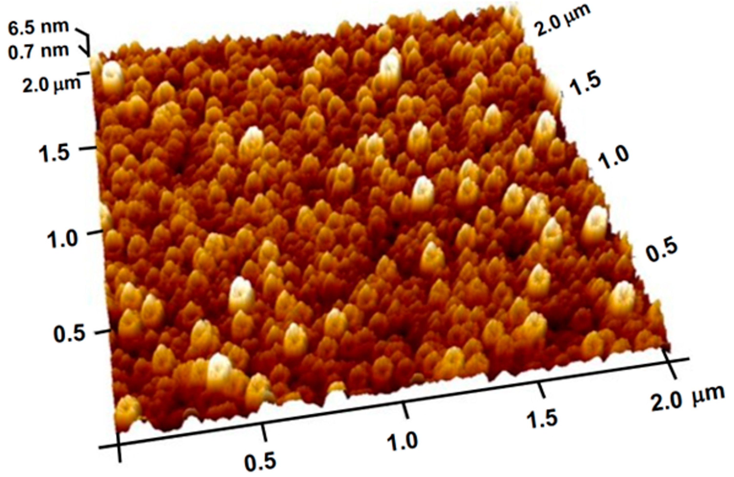
Surface morphology was evaluated by atomic force microscopy (AFM) on AZO deposited at a radio-frequency power of 150 W. A representative 2 µm × 2 µm scan (Figure 6) reveals a compact polycrystalline microstructure with a root-mean-square roughness of 1.5 nm and an average lateral grain size of 72 nm. Such low roughness minimizes interfacial scattering at the AZO/dielectric interface and is expected to reduce gate leakage and contact resistance in the final TFTs.

4.3. TFT Performance

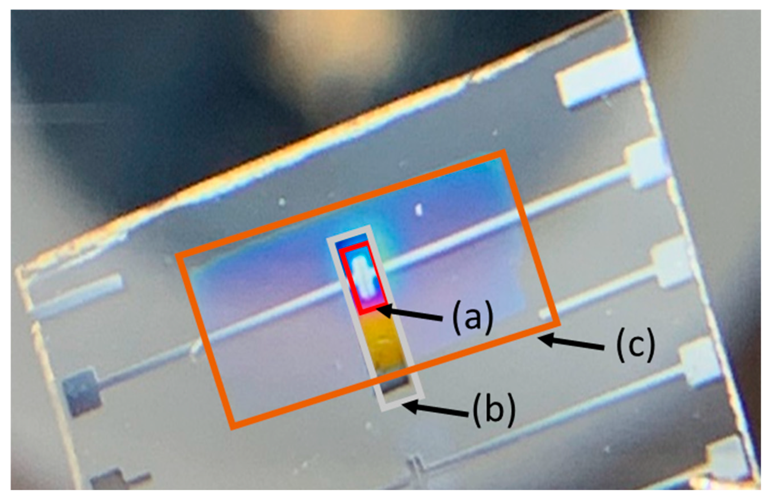
Figure 7 presents a schematic of the fabricated AZO-based thin-film transistor (TFT) with a staggered bottom-gate architecture. This configuration was selected due to its widespread use in liquid crystal display (LCD) technology, offering a simplified fabrication process and reliable electrical performance. Notably, the TFT was fabricated entirely at room temperature without any post-deposition annealing, demonstrating the feasibility of low-temperature processing.
Device fabrication began with the deposition of a high-permittivity (high-k) dielectric layer on both glass and silicon substrates to explore the influence of substrate type on device characteristics. A bottom contact mask defined the gate electrode, followed by patterning of the dielectric layer. The AZO semiconductor was deposited via RF magnetron sputtering through a shadow mask to define the active channel region. Finally, source and drain electrodes were deposited to complete the device. All TFTs featured a channel width (W) of 1 mm and a channel length (L) of 30 µm, yielding a W/L ratio of 33. The oxide capacitance (Cox) was measured to be 300 pF/m2 from capacitance–voltage (C–V) hysteresis data at 1 MHz.
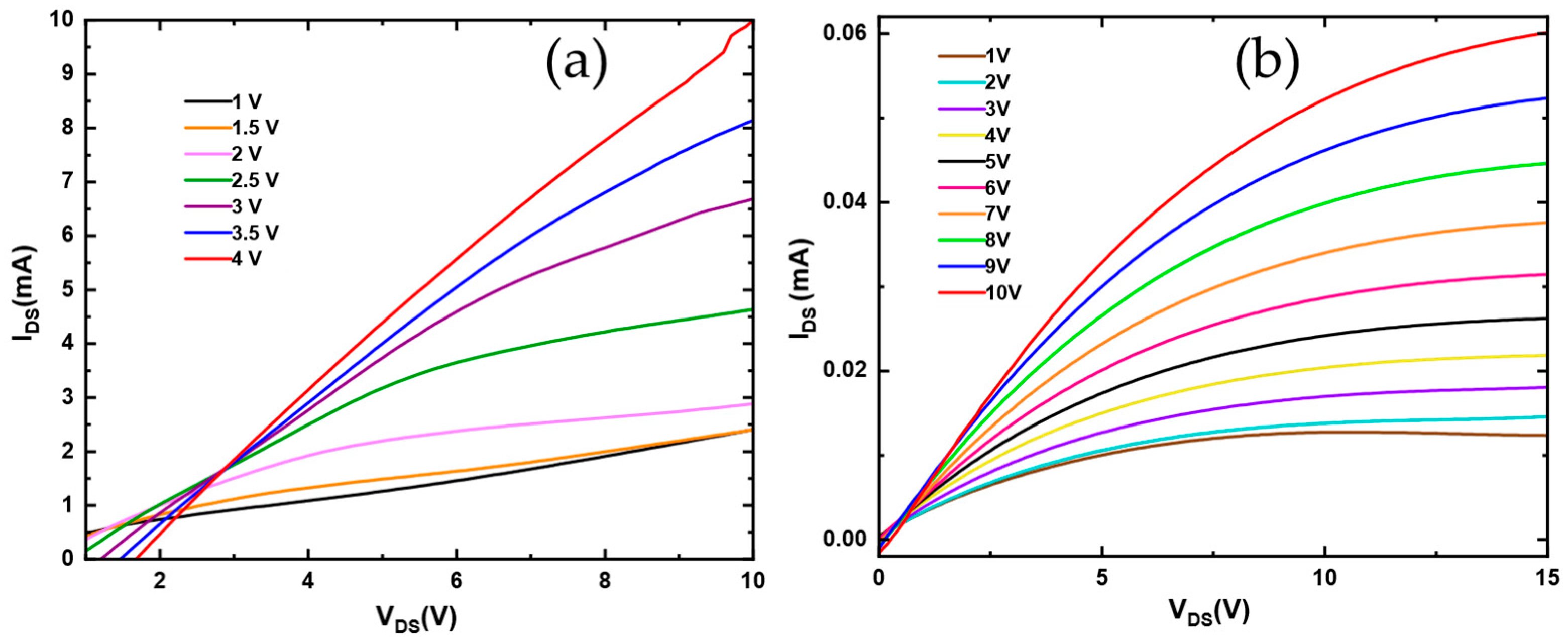
Figure 8a shows the transfer characteristics, while Figure 8b displays the output characteristics of the fabricated AZO TFT. The device exhibits typical n-channel field-effect transistor behavior, with clear gate-induced modulation and drain current saturation. Drain voltage sweeps from 0 to 7 V confirmed saturation behavior, with a sharp on/off transition observed with gate bias variation. At a gate voltage of 10 V, the TFT achieved a saturation current exceeding 3 mA.
Despite ambient conditions, the devices demonstrated stable and reproducible performance despite measurement constraints. Using linear fitting of the transfer curve in the saturation regime, the extracted field-effect mobility was 13.13 cm2/V·s. The threshold voltage (Vth) was determined to be approximately 4.1 V at a gate voltage of 5 V. These electrical properties may be further improved through thermal annealing, optimization of deposition temperature, and refinement of measurement conditions.
Zinc oxide is a chemically versatile material whose electrical and structural properties can be tuned by doping and environmental conditions. In this study, we specifically investigated the role of oxygen during AZO deposition. Reactive sputtering was performed with a controlled O2/Ar gas ratio to mitigate oxygen deficiency in the deposited AZO films. Argon was used as the primary sputtering gas, while oxygen was added to compensate for oxygen vacancies formed during physical vapor deposition.
Native defects, such as zinc interstitials and oxygen vacancies, are inherent in zinc oxide. Oxygen-related point defects—particularly zinc interstitials and oxygen vacancies—play a critical role in charge transport by modulating free carrier density. A reduced concentration of oxygen vacancies typically results in lower electrical conductivity of the AZO semiconductor active layer [57].
Figure 9 compares the performance of the TFT device based on the growth condition of the active AZO layer under oxygen partial pressures of 15% and 18% to obtain some insight into how varying oxygen concentrations impact the device’s performance.
Figure 9a,b compare AZO-based TFTs fabricated under identical power conditions with oxygen incorporation levels of 15% and 18%, respectively. The device with 15% oxygen (Figure 9a) exhibits basic transistor characteristics and gate voltage modulation but fails to reach the saturation regime. This behavior is likely due to a high concentration of zinc interstitials and oxygen vacancies, which enhance electron flow but prevent the device from achieving high output currents in the milliampere range. The corresponding AZO film shows a threshold voltage of approximately 6 V. In contrast, the device deposited with 18% oxygen (Figure 9b) demonstrates improved stability, with clear gate modulation and operation in the saturation region. However, this improvement comes at the cost of reduced saturation current due to fewer oxygen vacancies. These findings highlight the critical role of oxygen incorporation in tuning the electrical behavior of AZO films. Zinc oxide naturally contains native defects—zinc interstitials and oxygen vacancies—contributing to current flow. Increasing the oxygen content during deposition helps suppress oxygen vacancies, resulting in more controlled and stable transistor performance. Since the 18% O2 device exhibited the most stable characteristics, additional testing was conducted at gate voltages ranging from 1 V to 10 V, confirming consistent gate modulation and reliable saturation behavior.
To complement the qualitative discussion of oxygen vacancy effects, we estimated the effective carrier density in the AZO channel from the measured transfer characteristics. Using the gate capacitance of the ZrO2 dielectric layer (Cox ≈ 300 pF/m2) and the extracted threshold voltage (Vth ≈ 4.1), the induced carrier density was approximated using the following:
n C o x ( V G V t h ) q L · W
where VG is the applied gate bias, q is the elementary charge, W is the channel width (1 mm), and L is the channel length (30 µm) for the fabricated TFTs. At a gate voltage of 10 V, the device deposited with 18% O2 yielded an estimated carrier density on the order of 1018 cm−3. This value is consistent with previously reported carrier concentrations in oxygen-rich AZO thin films (1017–1018 cm−3) [58,59]. By contrast, the device that was grown under 15% O2 displayed higher conductivity and failed to exhibit current saturation, which is a behavior characteristic of oxygen-deficient films with excessive oxygen vacancies. Based on the observed transfer curve and comparison to literature trends, the carrier density in this case is expected to exceed 1019 cm−3, consistent with degenerate conduction regimes in ZnO-based oxides [60,61].
This quantitative assessment reinforces our conclusion that controlled oxygen incorporation during sputtering is crucial for tuning AZO conductivity. Oxygen-deficient growth enhances electron concentration via vacancy formation but degrades transistor switching performance, while oxygen-rich growth yields lower carrier density and more stable gate modulation. These results confirm the central role of oxygen vacancies in determining the balance between conductivity and transistor operability in AZO-based TFTs.
The benchmarking in Table 2 highlights the competitive performance of our devices fabricated using 3D-printed shadow masks. Our devices achieve a field-effect mobility of 13.1 cm2/V·s, which is on par with or higher than many conventional ALD-fabricated IGZO TFTs (μ ≈ 10–14 cm2/V·s) and far superior to ZnO/AZO double-active-layer TFTs (μ ≤ 0.01 cm2/V·s) and other indium-free sputtered devices (μ ≈ 10−3–10−2 cm2/V·s). Importantly, the threshold voltage of ~4.1 V is within the practical operating range and compares favorably to indium-free ZnO/AZO TFTs, which often suffer from large positive shifts (≈9–10 V).
The off-state current (Ioff) of our devices was calculated from the conductivity of the AZO active channel layer, measured using the four-point probe method. The 45 nm-thick AZO film exhibits a resistivity of approximately 500 Ω·m near room temperature, corresponding to a well-defined conductivity that ensures low leakage. We used the following relation [62,63]:
I o f f = σ   t   V D S W L
where σ is the channel conductivity, W and L are the channel width and length, t is the active layer thickness, and VDS is the drain-source bias, we estimate Ioff ≈ 10−10 A for our device geometry. The on-current (Ion) was obtained directly from transfer measurements, where our TFT reaches Ion ≈ 10−6 A at VDS = 14.5 V and VGS = 10 V. This yields an Ion/Ioff ratio of ~104, which is in excellent agreement with the experimental transfer curves.
While some state-of-the-art IGZO/GIZO heterojunction TFTs achieve higher Ion/Ioff ratios (≥106–108) and mobilities up to ~74 cm2/V·s, they require indium-rich compositions, patterned metal insertion, or Plasma-Enhanced Atomic Layer Deposition (PEALD) processing. These methods involve costly, high-temperature, and complex fabrication steps. In contrast, our approach delivers competitive performance through a simple, indium-free, room-temperature fabrication process using 3D-printed masks, avoiding the need for annealing or photolithography.
These results establish a strong performance-to-cost advantage. Our TFTs simultaneously offer high mobility, a favorable threshold voltage, and robust Ion/Ioff switching characteristics, achieved with a fabrication strategy that is scalable, low in cost, and environmentally sustainable. This positions our work as a practical and impactful contribution to the development of transparent and flexible oxide electronics.
Table 2. Performance comparison of this work with representative oxide TFTs reported in the literature.
Material/Device (Structure)Mobility (cm2/V·s)Vth (V)Ion/IoffKey NotesReference
This work (3D-printed mask)13.1~4.1104Room-temperature, indium-free, no annealingThis work
a-IGZO TFT with AZO/IGZO bi-layer S/D contacts13.70.6106Heterojunction S/D contacts[64]
ZnO/AZO or AZO/ZnO double-active-layer TFTs (sputtered, RT + anneal)0.012.9105Anneal optimization required[65]
Indium-free ZnO/AZO double-active-layer TFT (sputtered, RT)4 × 10−39.5104Room temp, indium-free[65]
a-IGZO/flexible IGZO TFTs (HfO2/Al2O3/HfO2 dielectric)100.35106Low-voltage flexible circuits[66]
a-IGZO/a-GIZO high-mobility engineering74−1.3108PEALD, patterned metal insertion[67]
Indium-free ZnO/AZO double-active-layer TFT (sputtered, RT)2.9 × 10⁻³ 103Room temp, indium-free[65]
a-InSnO/IGZO heterojunction TFT (ALD)14.1−0.5108High stability ALD[68]

5. Conclusions

This study presents a detailed investigation of the electrical, optical, and structural properties of AZO and high-k ZrO2 thin films to evaluate their suitability for device integration. Four-point probe measurements confirmed the semiconducting nature of the AZO channel layer, which is essential for thin-film transistor (TFT) operation. Atomic force microscopy revealed smooth surface morphologies for both AZO and ZrO2 films. Additionally, ZrO2 exhibited stable capacitance–voltage (C–V) characteristics, with clear distinctions among accumulation, depletion, and inversion regions in MOSCAP structures, confirming its reliability as a dielectric layer.
Using a low-cost 3D-printed shadow mask, we successfully fabricated an AZO-based TFT without photolithography. The device demonstrated stable electrical behavior, including effective gate voltage modulation and current saturation. These findings highlight the potential of AZO and ZrO2 as promising materials for scalable and cost-effective next-generation electronics.
This work demonstrates the fabrication of indium-free thin-film transistors (TFTs) using a single-step, 3D-printed shadow mask approach. By integrating aluminum-doped zinc oxide (AZO) as the semiconductor channel and zirconium oxide (ZrO2) as the high-k dielectric, devices were fabricated entirely at room temperature without post-deposition annealing or photolithography. Structural and dielectric characterization confirmed smooth morphologies and stable C–V behavior, validating the suitability of both AZO and ZrO2 for device integration.
The fabricated TFTs exhibited a field-effect mobility of 13.1 cm2/V·s, a threshold voltage of ~4.1 V, and an on/off ratio of ~104, demonstrating reliable gate modulation and current saturation. The off-state current was estimated from AZO conductivity to be on the order of 10−10 A, consistent with the measured transfer characteristics, while the on-state current reached ~10−6 A. These results highlight the balance between mobility, threshold stability, and switching capability achievable under simplified processing.
Benchmarking against the literature shows that our devices rival ALD-processed IGZO TFTs and outperform other reported indium-free ZnO/AZO devices, while avoiding reliance on scarce indium and eliminating the need for high-temperature or vacuum-assisted processing. Although some IGZO/GIZO heterojunctions achieve higher mobility through complex methods such as patterned metal insertion or PEALD, these approaches require costly infrastructure.
In contrast, the proposed 3D-printed shadow mask route offers a scalable, low-cost, and sustainable fabrication strategy. The demonstrated performance-to-cost advantage underscores its promise for large-area, transparent, and flexible electronics, marking a step toward practical next-generation oxide semiconductor technologies.

Author Contributions

K.A.Y., S.K.P. and M.B. Conceptualization, Methodology, data analysis, writing, original draft preparation, review; M.K.B. Conceptualization, software, data analysis, writing, review. All authors have read and agreed to the published version of the manuscript.

Funding

This work was supported by the NSF-CREST (CREAM), Grant No. 1547771, and NSF-EiR grant number 2200397.

Data Availability Statement

The raw data supporting the conclusions of this article will be made available by the authors on request.

Conflicts of Interest

All authors are contributing to this research work and declaim that there are no conflicts of interest.

References

  1. Choi, J.H.; Yang, J.H.; Pi, J.E.; Hwang, C.Y.; Kim, Y.H.; Kim, G.H.; Kim, H.O.; Hwang, C.S. The New Route for Realization of 1-µm-Pixel-Pitch High-Resolution Displays. J. Soc. Inf. Disp. 2019, 27, 487–496. [Google Scholar] [CrossRef]
  2. Ohara, M.; Kohda, T.; Furuichi, S.; Nakada, T.; Kawase, K.; Kohda, Y.; Ishikawa, T.; Sumiyoshi, K.; Funakoshi, A. 13.2: Invited Paper: Recent Progress and Future Trend of Ultra-High-Resolution Large-Sized TFT-LCD Monitor Electronics. SID Symp. Dig. Tech. Pap. 2002, 33, 168–171. [Google Scholar] [CrossRef]
  3. Kaya, S.; Schmidl, D.; Schmetterer, L.; Witkowska, K.J.; Unterhuber, A.; Aranha Dos Santos, V.; Baar, C.; Garhofer, G.; Werkmeister, R.M. Effect of Hyaluronic Acid on Tear Film Thickness as Assessed with Ultra-High Resolution Optical Coherence Tomography. Acta Ophthalmol. 2015, 93, 439–443. [Google Scholar] [CrossRef]
  4. Komatsu, R.; Nakazato, R.; Sasaki, T.; Suzuki, A.; Senda, N.; Kawata, T.; Jimbo, Y.; Aoyama, T.; Ohno, N.; Kawashima, S.; et al. Repeatedly Foldable AMOLED Display. J. Soc. Inf. Disp. 2015, 23, 41–49. [Google Scholar] [CrossRef]
  5. Noda, M.; Kobayashi, N.; Katsuhara, M.; Yumoto, A.; Ushikura, S.; Yasuda, R.; Hirai, N.; Yukawa, G.; Yagi, I.; Nomoto, K.; et al. An OTFT-driven rollable OLED display. J. Soc. Inf. Disp. 2011, 19, 316–322. [Google Scholar] [CrossRef]
  6. Yarbrough, K.A.; Behera, M.K.; Beckford, J.; Pradhan, S.K.; Bahoura, M. Observation of MOSFET like behavior of a TFT based on amorphous oxide semiconductor channel layer with suitable integration of atomic layered deposited high-k gate dielectrics. AIP Adv. 2023, 13, 025041. [Google Scholar] [CrossRef]
  7. Jia, Y.; Liu, Z.; Wu, D.; Chen, J.; Meng, H. Mechanical Simulation of Foldable AMOLED Panel with a Module Structure. Org. Electron. 2019, 65, 185–192. [Google Scholar] [CrossRef]
  8. Mizukami, M.; Cho, S.-I.; Watanabe, K.; Abiko, M.; Suzuri, Y.; Tokito, S.; Kido, J. Flexible Organic Light-Emitting Diode Displays Driven by Inkjet-Printed High-Mobility Organic Thin-Film Transistors. IEEE Electron Device Lett. 2018, 39, 39–42. [Google Scholar] [CrossRef]
  9. Mativenga, M.; Geng, D.; Kim, B.; Jang, J. Fully Transparent and Rollable Electronics. ACS Appl. Mater. Interfaces 2015, 7, 1578–1585. [Google Scholar] [CrossRef]
  10. Jin, D.-U.; Kim, T.-W.; Koo, H.-W.; Stryakhilev, D.; Kim, H.-S.; Seo, S.-J.; Kim, M.-J.; Min, H.-K.; Chung, H.-K.; Kim, S.S. Highly Robust Flexible AMOLED Display on Plastic Substrate with New Structure. SID Symp. Dig. Tech. Pap. 2010, 41, 703–705. [Google Scholar] [CrossRef]
  11. Jang, H.J.; Lee, J.Y.; Kwak, J.; Lee, D.; Park, J.-H.; Lee, B.; Noh, Y.Y. Progress of Display Performances: AR, VR, QLED, OLED, and TFT. J. Inf. Disp. 2019, 20, 1–8. [Google Scholar] [CrossRef]
  12. Peng, C.; Huang, H.; Xu, M.; Chen, L.; Li, X.; Zhang, J. A Simple Doping Process Achieved by Modifying the Passivation Layer for Self-Aligned Top-Gate In-Ga-Zn-O Thin-Film Transistors at 200 °C. Nanomaterials 2022, 12, 4021. [Google Scholar] [CrossRef]
  13. Peng, C.; Xu, M.; Chen, L.; Li, X.; Zhang, J. Improvement of Properties of Top-gate IGZO TFT by Oxygen-Rich Ultrathin in Situ ITO Active Layer. Jpn. J. Appl. Phys. 2022, 61, 070914. [Google Scholar] [CrossRef]
  14. Peng, C.; Yang, S.; Pan, C.; Li, X.; Zhang, J. Effect of Two-Step Annealing on High Stability of a-IGZO Thin-Film Transistor. IEEE Trans. Electron Devices 2020, 67, 4262–4268. [Google Scholar] [CrossRef]
  15. Liu, Y.; Li, X.; Ge, L.; Zhang, Z. Ultralarge-Area Stitchless Scanning Probe Lithography and In Situ Characterization System Using a Compliant Nanomanipulator. IEEE/ASME Trans. Mechatron. 2024, 29, 924–935. [Google Scholar] [CrossRef]
  16. Wu, Y.; Chiu, G. Modeling Height Profile for Drop-on-Demand Print of UV Curable Ink. In Proceedings of the ASME 2019 Dynamic Systems and Control Conference, Park City, UT, USA, 8–11 October 2019; 8p. [Google Scholar] [CrossRef]
  17. Zaho, K.; Ye, Z.; Su, Z.; Cao, W.; Shi, D.; Hao, X.; Zhang, S.; Wang, Z.; Xu, X.; Zhu, J. A diffusion-controlled kinetic model for binder burnout in a green part fabricated by binder jetting based on the thermal decomposition kinetics of TEG-DMA. Add. Manuf. 2025, 105, 104793. [Google Scholar]
  18. Wu, W.; Chen, Y.; Xie, B.; Wu, H.; Cheng, L.; Guo, Y.; Cai, C.; Hou, M.; Chen, X. Microdynamic behaviors of Au/Ni-assisted chemical etching in fabricating silicon nanostructures. Appl. Surf. Sci. 2025, 696, 162915. [Google Scholar] [CrossRef]
  19. Moyen, E.; Kim, J.H.; Kim, J.; Jang, J. Zno Nanoparticles for Quantum-Dot-Based Light-Emitting Diodes. ACS Appl. Nano Mater. 2020, 3, 5203–5211. [Google Scholar] [CrossRef]
  20. Han, W.; Oh, S.; Lee, C.; Kim, J.; Park, H.-H. Zno Nanocrystal Thin Films for Quantum-Dot Light-Emitting Devices. ACS Appl. Nano Mater. 2020, 3, 7535–7542. [Google Scholar] [CrossRef]
  21. Xiong, S.X.; Hu, L.; Hu, L.; Sun, L.L.; Qin, F.; Liu, X.J.; Fahlman, M.; Zhou, Y.H. 12.5% Flexible Nonfullerene Solar Cells by Passivating the Chemical Interaction Between the Active Layer and Polymer Interfacial Layer. Adv. Mater. 2019, 31, 1806616. [Google Scholar] [CrossRef]
  22. Wei, J.F.; Ji, G.Q.; Zhang, C.J.; Yan, L.P.; Luo, Q.; Wang, C.; Chen, Q.; Yang, J.L.; Chen, L.W.; Ma, C.Q. Silane-Capped ZnO Nanoparticles for Use as the Electron Transport Layer in Inverted Organic Solar Cells. ACS Nano 2018, 12, 5518–5529. [Google Scholar] [CrossRef]
  23. Guo, L.; Yang, Z.; Dou, X. Artificial Olfactory System for Trace Identification of Explosive Vapors Realized by Optoelectronic Schottky Sensing. Adv. Mater. 2017, 29, 1604528. [Google Scholar] [CrossRef]
  24. Nasiri, N.; Bo, R.H.; Wang, F.; Fu, L.; Tricoli, A. Ultraporous Electron-Depleted Zno Nanoparticle Networks for Highly Sensitive Portable Visible-Blind Uv Photodetectors. Adv. Mater. 2015, 27, 4336–4343. [Google Scholar] [CrossRef]
  25. Xie, J.; Cao, Y.; Jia, D.; Li, Y.; Wang, Y. Solid-State Synthesis of Y-Doped ZnO Nanoparticles with Selective-Detection Gas-Sensing Performance. Ceram. Int. 2016, 42, 90–96. [Google Scholar] [CrossRef]
  26. Gurav, K.V.; Gang, M.G.; Shin, S.W.; Patil, U.M.; Deshmukh, P.R.; Agawane, G.L.; Suryawanshi, M.P.; Pawar, S.M.; Patil, P.S.; Lokhande, C.D.; et al. Gas Sensing Properties of Hydrothermally Grown ZnO Nanorods with Different Aspect Ratios. Sens. Actuators B Chem. 2014, 190, 439–445. [Google Scholar] [CrossRef]
  27. Huang, K.; Wu, J.; Chen, Z.; Xu, H.; Wu, Z.; Tao, K.; Yang, T.; Wu, Q.; Zhou, H.; Huang, B.; et al. Nanostructured High-Performance Thin-Film Transistors and Photo-transistors Fabricated by a High-Yield and Versatile Near-Field Nanolithography Strategy. ACS Nano 2019, 13, 6618–6630. [Google Scholar] [CrossRef]
  28. Park, J.-H.; Park, J.H.; Biswas, P.; Kwon, D.K.; Han, S.W.; Baik, H.K.; Myoung, J.-M. Adopting Novel Strategies in Achieving High-Performance Single-Layer Network Structured ZnO Nanorods Thin Film Transistors. ACS Appl. Mater. Interfaces 2016, 8, 11564–11574. [Google Scholar] [CrossRef]
  29. Beckford, J.; Behera, M.K.; Yarbrough, K.A.; Pradhan, S.K.; Bahoura, M. Influence of oxygen on the optical, electrical, and heating properties of gallium-doped zinc oxide (GZO) films. AIP Adv. 2023, 13, 025249. [Google Scholar] [CrossRef]
  30. Beckford, J.; Behera, M.K.; Yarbrough, K.A.; Obasogie, B.; Pradhan, S.K.; Bahoura, M. Gallium doped zinc oxide thin films as transparent conducting oxide for thin-film heaters. AIP Adv. 2021, 11, 075208. [Google Scholar] [CrossRef]
  31. Nomura, K.; Ohta, H.; Takagi, A.; Kamiya, T.; Hirano, M.; Hosono, H. Room-Temperature Fabrication of Transparent Flexible Thin-Film Transistors Using Amorphous Oxide Semiconductors. Nature 2004, 432, 488–492. [Google Scholar] [CrossRef]
  32. Lokanc, M.; Eggert, R.; Redkinger, M. The Availability of Indium: The Present, Medium Term, and Long Term. Available online: https://www.nrel.gov/docs/fy16osti/62409.pdf (accessed on 8 September 2025).
  33. Oh, H.; Yoon, S.M.; Ryu, M.K.; Hwang, C.S.; Yang, S.; Park, S.H.K. Photon-Accelerated Negative Bias Instability Involving Sub-Gap States Creation in Amorphous In–Ga–Zn–O Thin Film Transistor. Appl. Phys. Lett. 2010, 9, 183502. [Google Scholar] [CrossRef]
  34. Migliorato, P.; Chowdhury, M.D.H.; Um, J.G.; Seok, M.; Jang, J. Light/negative Bias Stress Instabilities in Indium Gallium Zinc Oxide Thin Film Transistors Explained by Creation of a Double Donor. Appl. Phys. Lett. 2012, 101, 123502. [Google Scholar] [CrossRef]
  35. Oh, H.; Yoon, S.M.; Ryu, M.K.; Hwang, C.S.; Yang, S.; Park, S.H.K. Transition of Dominant Instability Mechanism Depending on Negative Gate Bias Under Illumination in Amorphous In-Ga-Zn-O Thin Film Transistor. Appl. Phys. Lett. 2011, 98, 033504. [Google Scholar] [CrossRef]
  36. Chowdhury, M.D.H.; Ryu, S.H.; Migliorato, P.; Jang, J. Effect Of Annealing Time on Bias Stress and Light-Induced Instabilities in Amorphous Indium–Gallium–Zinc-Oxide Thin Film Transistors. J. Appl. Phys. 2011, 110, 114503. [Google Scholar] [CrossRef]
  37. Ueoka, Y.; Ishikawa, Y.; Bermundo, J.P.; Yamazaki, H.; Urakawa, S.; Fujii, M.; Horita, M.; Uraoka, Y. Density of States in Amorphous In-Ga-Zn-O Thin Film Transistor Under Negative Bias Illumination Stress. ECS J. Solid State Sci. Technol. 2014, 3, Q3001–Q3004. [Google Scholar] [CrossRef]
  38. Lu, B.; Li, D.; Tian, X. Development Trends in Additive Manufacturing and 3D printing. Engineering 2015, 1, 85–89. [Google Scholar] [CrossRef]
  39. Vazquez-Mena, O.; Villanueva, L.G.; Savu, V.; Sidler, K.; Langlet, P.; Brugger, J. Analysis of the Blurring in Stencil Lithography. Nanotechnology 2009, 20, 415303. [Google Scholar] [CrossRef]
  40. Bhaskar, P.; Mathioudakis, S.; Olschewski, T.; Muckel, F.; Bindel, J.R.; Pratzer, M.; Liebmann, M.; Morgenstern, M. Mask Aligner for Ultrahigh Vacuum with Capacitive Distance Control. Appl. Phys. Lett. 2018, 112, 161602. [Google Scholar] [CrossRef]
  41. Lishchynska, M.; Bourenkov, V.; van den Boogaart, M.A.F.; Doeswijk, L.; Brugger, J.; Greer, J.C. Predicting Mask Distortion, Clogging and Pattern Transfer for Stencil Lithography. Microelectron. Eng. 2007, 84, 42–53. [Google Scholar] [CrossRef]
  42. Decker, W.; Belan, R.; Heydemann, V.D.; Armstrong, S.; Fisher, T. Novel Low Pressure Sputtering Source and Improved Vacuum Deposition of Small Patterned Features Using Precision Shadow Masks. In Proceedings of the 59th Annual Technical Conference Proceedings, Indianapolis, IN, USA, 9–13 May 2016. [Google Scholar] [CrossRef]
  43. Yi, S.M.; Jin, S.H.; Lee, J.D.; Chu, C.N. Fabrication of a High-Aspect-Ratio Stainless Steel Shadow Mask and Its Application to Pentacene Thin-Film Transistors. J. Micromech. Microeng. 2005, 15, 263–269. [Google Scholar] [CrossRef]
  44. Bartsch, H.; Jaziri, N.; Jaekel, K.; Nessimian, N.; Müller, J. Shadow Masks as an Alternative Method to Lithography for the Structuring of Thin Film Layers on LTCC Substrates. In Proceedings of the IMAPS 2023 Joint Conferences—HiTEC, CICMT, Power Packaging, Albuquerque, NM, USA, 17–20 April 2023. [Google Scholar]
  45. Cha, C.; Jo, E.; Kim, Y.; Choi, A.J.; Han, K. 3D-Printed Shadow Masks for Micro-Patterned Electrodes. RSC Adv. 2024, 14, 34586–34593. [Google Scholar] [CrossRef]
  46. Rahiminejad, S.; Köhler, E.; Enoksson, P. Direct 3D Printed Shadow Mask on Silicon. J. Phys. Conf. Ser. 2016, 757, 012021. [Google Scholar] [CrossRef]
  47. Marques, J.P. Development of High-Resolution Shadow Masks Using Thin Membranes: Limitations Imposed by Mask Thickness and Aspect Ratio; University of Lisbon: Lisbon, Portugal, 2019. [Google Scholar]
  48. Stencils Unlimited. Shadow Masks for Deposition Design Guidelines. Tech. Blog 2023. Available online: https://www.stencilsunlimited.com/blog/shadow-masks-for-deposition-design-guidelines/ (accessed on 8 September 2025).
  49. Nanoscribe GmbH. Two-Photon Polymerization (2PP): High-Resolution 3D Printing Technology for Submicron Features. Prod. Technol. Overv. 2025. Available online: https://www.nanoscribe.com/en/microfabrication-technologies/2pp-two-photon-polymerization/ (accessed on 8 September 2025).
  50. Microlight3D. Two-Photon Polymerization Technology: Achieving Voxel Resolutions ~0.2 µm. Technol. Brief 2025. Available online: https://www.microlight3d.com/technology/two-photon-polymerization (accessed on 8 September 2025).
  51. LLNL. Parallel Two-Photon Polymerization (TPL) for Scalable Submicron Additive Manufacturing: Less than 350 nm In-Plane Resolution and <5 µm Depth Resolution. Technol. Descr. 2025. Available online: https://ipo.llnl.gov/technologies/advanced-manufacturing/parallel-two-photon-polymerization-scalable-submicron-additive (accessed on 8 September 2025).
  52. Gierałtowska, S.; Sztenkiel, D.; Guziewicz, E.; Godlewski, M.; Luka, G.; Witkowski, B.S.; Wachnicki, Ł.; Łusakowska, E.; Dietl, T.; Sawicki, M. Properties and Characterization of ALD Grown Dielectric Oxides for MIS Structures. Acta Phys. Pol. A 2011, 119, 692–695. [Google Scholar] [CrossRef]
  53. Carrasco, I.S.S.; To, T.B.T.; Reis, F.D.A.A. Scaling of Surface Roughness in Film Deposition with Height-Dependent Step Edge Barriers. Phys. Rev. E 2023, 108, 064802. [Google Scholar] [CrossRef] [PubMed]
  54. Das, S.; Neogi, S.; Mukherjee, M. Effect of Temperature and Deposition Rate on the Surface Morphology of Thin Al Metal Films on Glass Substrate Application in Solar Cell. J. Phys. Conf. Ser. 2020, 1579, 012019. [Google Scholar] [CrossRef]
  55. Ding, S.; Zhao, J.; Yu, Q. Effect of Zirconia Polymorph on Vapor Phase Ketonization of Propoionic Acid. Catalysts 2019, 9, 768. [Google Scholar] [CrossRef]
  56. Mih, T.; Paul, S.; Milanov, A.; Bhakta, R.; Devi, A. Capacitance-Voltage Analysis of ZrO2 Thin Films Deposited by Thermal MOCVD Technique. ECS Trans. 2009, 25, 901. [Google Scholar] [CrossRef]
  57. Kim, S.; Moon, Y.; Moon, D.; Hong, M.; Jeon, Y.; Park, J. Influence of Oxygen on the Electrical Properties of Aluminum Doped Zinc-Oxide Thin Films. J. Kor. Phys. Soc. 2006, 49, 1256–1259. [Google Scholar]
  58. Look, D.C. Recent Advances in ZnO Materials and Devices. Mater. Sci. Eng. 2001, 80, 383–387. [Google Scholar] [CrossRef]
  59. Novák, P.; Nedvědová, L.; Kozák, T.; Šotová, P.; Bláhová, O.; Jansa, Z.; Medlín, R.; Netrvalová, M.F.; Minár, J. Investigation of Carrier Transport in ZnO and ZnO: Al Thin Films Sputtered at Different Oxygen Conditions. Thin Solid Films 2023, 780, 139942. [Google Scholar] [CrossRef]
  60. Zhang, S.B.; Wei, S.H.; Zunger, A. Intrinsic n-Type versus p-Type Doping Asymmetry and the Defect Physics of ZnO. Phys. Rev. 2001, 63, 075205. [Google Scholar] [CrossRef]
  61. Ellmer, K. Resistivity of Polycrystalline Zinc Oxide Films: Current Status and Physical Limit. J. Phys. D Appl. Phys. 2001, 34, 3097–3108. [Google Scholar] [CrossRef]
  62. Chung, J.H.; Lee, J.Y.; Kim, H.S.; Jang, N.W.; Kim, J.H. Effect of thickness of ZnO active layer on ZNO-TFT’s characteristic. Thin Solid Films 2008, 516, 5597–5601. [Google Scholar] [CrossRef]
  63. Zeng, Y.; Ning, H.; Zheng, Z.; Zhang, H.; Fang, Z.; Yao, R.; Xu, M.; Wang, L.; Lan, L.; Peng, J.; et al. Island-like AZO/Al2O3 bilayer channel structure for thin film transistors. Adv. Mater. Interfaces 2017, 4, 1700063. [Google Scholar] [CrossRef]
  64. Zou, X.; Fang, G.; Wan, J.; Liu, N.; Long, H.; Wang, H.; Zhao, X. Enhanced Performance of a-IGZO Thin-Film Transistors by Forming AZO/IGZO Heterojunction Source/Drain Contacts. Semicond. Sci. Technol. 2011, 26, 055003. [Google Scholar] [CrossRef]
  65. Yan, X.; Song, K.; Li, B.; Zhang, Y.; Yang, F.; Wang, Y.; Wang, C.; Chi, Y.; Yang, X. Performance Enhancement for Indium-Free Metal Oxide Thin-Film Transistors with Double-Active-Layers by Magnetron Sputtering at Room Temperature. Micromachines 2022, 13, 2024. [Google Scholar] [CrossRef] [PubMed]
  66. Bao, B.; Karnaushenko, D.D.; Xu, J.; Wang, S.; Bandari, V.K.; Schmidt, O.G.; Karnaushenko, D. Flexible IGZO TFT Technology for Shift Register Drivers. Adv. Electron. Mater. 2024, 10, 2400036. [Google Scholar] [CrossRef]
  67. Sheng, J.; Hong, T.; Lee, H.M.; Kim, K.; Sasase, M.; Kim, J.; Hosono, H.; Park, J.S. Amorphous IGZO TFT with High Mobility of ∼70 cm2 V−1 s−1 via Vertical Dimension Control Using PEALD. ACS Appl. Mater. Interfaces 2019, 11, 40401–40409. [Google Scholar] [CrossRef]
  68. Huang, X.; Chen, C.; Sun, F.; Chen, X.; Xu, W.; Li, L. Enhancing the Carrier Mobility and Bias Stability in Metal–Oxide Thin Film Transistors with Bilayer InSnO/a-InGaZnO Heterojunction Structure. Micromachines 2024, 15, 512. [Google Scholar] [CrossRef] [PubMed]
Figure 1. Three-dimensional STL files for the bottom contact, dielectric mask and active layer masks.
Processes 13 02976 g001
Figure 2. (a) Schematic diagram of the MOSCAP structure. (b) Schematic diagram of the TFT device with the staggered bottom gate structure.
Processes 13 02976 g002
Figure 3. (a) Three-dimensional AFM surface morphology scan of ZrO2 and (b) XRD spectra of the ZrO2 thin film.
Processes 13 02976 g003
Figure 4. Capacitance–voltage measurements of ZrO2 films at various frequencies.
Processes 13 02976 g004
Figure 5. (a) AZO four-point probe sheet resistance measurements at different RF sputtering AZO thin films. (b) Transmission spectra of different RF sputtering AZO thin films.
Processes 13 02976 g005
Figure 6. AFM surface morphology scan of AZO film grown at 150 W sputtering power.
Processes 13 02976 g006
Figure 7. Developed a TFT device highlighting the different layers deposited. (a) Semiconductor active layer (AZO); (b) bottom contact (titanium); and (c) dielectric layer purple color (ZrO2).
Processes 13 02976 g007
Figure 8. (a) Saturation curves of the AZO-based TFT. (b) Output characteristics of the AZO TFT.
Processes 13 02976 g008
Figure 9. Saturation curves of AZO-based TFT oxygen incorporation at (a) 15 percent with a gate voltage of 1 V–4 V and (b) 18 percent with a gate voltage of 1 V–10 V.
Processes 13 02976 g009
Table 1. Comparison of conventional and emerging shadow mask fabrication methods.
AspectFDM (ABS) Shadow MasksHigh-Definition 3D (MJP)Multiphoton/µSLA Techniques
Feature resolution≈100–400 µm (no finer than nozzle size)~1 mm features, better fidelitySub-micron to ~100 nm achievable
Mask thickness~1–2 mm for stabilitySimilar or thickerThin, high-fidelity masks via resin structures
Sub-micron feasibilityNoNoYes, in principle (via different methods)
Large-area scalingLimited by alignment, deformation, depositionImproved but still limitedNot typical; fundamentally different process
Material constraintsABS (thermal, mechanical limitations)Photopolymers (post-processing needed)Resin materials, special development
Disclaimer/Publisher’s Note: The statements, opinions and data contained in all publications are solely those of the individual author(s) and contributor(s) and not of MDPI and/or the editor(s). MDPI and/or the editor(s) disclaim responsibility for any injury to people or property resulting from any ideas, methods, instructions or products referred to in the content.