Abstract
Entry stability in ultra-thick coal seam longwall mining is often challenged by high abutment pressures and the need for wide coal pillars. This study presents the design, implementation, and verification of a hydraulic fracturing pressure relief strategy to optimize pillar width and improve entry performance in the longwall panels of Buliangou Mine. A site-specific fracturing scheme was applied near the coal pillar, using staged multi-interval fracturing from angled boreholes in the roof strata. Field instrumentation, including borehole imaging, water pressure monitoring, and stress/strain sensors, confirmed successful fracture propagation and significant stress redistribution. Post-fracturing monitoring indicated a shift in peak pillar stress location and an expansion of the elastic core zone, with entry deformation (ribs and roof-floor convergence) reduced by up to 25%. Based on these results and comparative case studies, an optimized 26 m pillar width was proposed and subsequently implemented in a new longwall panel. Field verification demonstrated stable entry conditions, consistent support loading, and a notable increase in coal recovery. This study confirms that hydraulic fracturing, when combined with detailed field design and monitoring, provides a reliable solution for stress management and pillar size reduction in ultra-thick seam longwall mining.
1. Introduction
Hydraulic fracturing has long been established as a fundamental technology for rock mass stimulation, stress relief, and strata control in underground mining and petroleum engineering [1,2]. Typically, this technology was first successfully tested in Kansas, USA, in 1947 [2]. Originally developed to enhance the productivity of oil and gas wells, the technique has since evolved into a widely adopted method across geotechnical and geological engineering disciplines [3,4,5]. Its applications now span stimulation of low-permeability hydrocarbon reservoirs, geothermal energy extraction, in situ stress measurements, radioactive waste disposal, rock mass permeability enhancement, and analysis of underground grouting and igneous intrusion mechanisms [6,7,8,9].
Hydraulic fracturing—also referred to as hydrofracturing or hydraulic splitting, depending on the context—involves injecting high-pressure fluid into rock masses to initiate and propagate fractures [10,11,12]. These induced fractures significantly alter the mechanical and hydraulic properties of the rock, making the technology highly valuable for both research and practical engineering purposes. The use of hydraulic fracturing for in situ stress measurement was first proposed by Hubbert and Willis (1957) [1]. In their method, pressurized water is injected into vertical boreholes to identify the orientation and magnitude of the two horizontal principal stresses, while the vertical stress is typically calculated from overburden density. This approach, which assumes a plane strain condition, remains a cornerstone of modern geomechanics. Since its introduction, extensive in situ stress testing has been performed globally, yielding valuable datasets [13,14].
Over the decades, the fluid dynamics and fracture propagation characteristics of hydraulic fracturing have been explored extensively. Osiptsov (2017) provided a comprehensive review of fluid mechanics in hydraulic fracturing, shedding light on multiphase flows and fracture tip propagation [15], while Montgomery and Smith (2010) detailed the historical evolution and technological endurance of hydraulic fracturing in petroleum engineering [2]. In the mining context, Rummel (1987) approached hydraulic fracturing from a fracture mechanics perspective, enabling more precise stress measurements and roof control designs [16]. Most importantly, hydraulic fracturing has proven especially effective in enhancing gas recovery from low-permeability coal seams [17]. By creating a network of primary and secondary fractures, it increases the surface area for gas desorption and migration, thereby improving production rates and reservoir sustainability [14,18,19]. High-pressure fluids expand and connect both pre-existing and newly formed fractures, significantly improving permeability within the coal seam [20].
In addition, ground controls in entries and longwall faces are the hot topics in underground mining, as shown in Figure 1 (Kang et al., 2015 and 2011 [21,22]). In recent years, the application of hydraulic fracturing has evolved into a strategic tool in underground coal mining [23], particularly for high-stress and ultra-thick seam conditions. Particularly, its application has expanded into roof control within underground coal mines—for managing thick and competent strata that overlie longwall panels [11,24,25,26]. Kang et al. (2023) applied directional borehole hydraulic fracturing to achieve stress relief and roof weakening in extra-thick seams, demonstrating significant improvement in strata behavior [27]. In another comprehensive case study, Kang et al. (2023) documented the application of large-scale hydraulic fracturing (LHF) to mitigate microseismic activity and manage induced stresses [28]. Similarly, the directional hydraulic fracturing technique was used by [29] in the Mengcun Coal Mine to mitigate coal burst risk, confirming its preconditioning effectiveness in deep mining operations.
Figure 1.
Longwall mining and hydraulic fracturing methodology diagram [30].
Recent studies have also highlighted the benefits of hydraulic fracturing for entry protection and gob-side entry stability [24]. Zou et al. (2024) investigated fracture mechanics in preventing mining-induced earthquakes for protecting entries [12], while Huang et al. (2018) proposed reasonable breaking positions in overhanging hard roofs for directional fracturing to reduce deformation [31]. Liu et al. (2020) developed a method to create vertical fractures in strong hanging roofs for stress relief [26]. In addition, in hard rock environments, the hydraulic fracturing technique has also informed secondary oil recovery strategies and geothermal energy development [11,26,32,33,34]. These efforts have laid a strong foundation for the strategic integration of hydraulic fracturing in strata management and ground control.
In summary, previous research indicates that hydraulic fracturing serves as a powerful tool to reduce stress, control roof behavior, and optimize mining layouts—especially in ultra-thick coal seams. However, there is limited research on hydraulic fracturing pressure relief for pillar size optimization in ultra-thick coal seam longwall panels. The present study aims to evaluate how hydraulic fracturing can be used not only as a stress relief measure but also as a means to optimize pillar width without compromising entry stability in ultra-thick seam longwall mining systems. Particularly, the current study explores the use of hydraulic fracturing to precondition the thick and hard overburden above the coal pillar, targeting the strata along the main tailgate entry. The high-pressure fracturing aims to induce controlled roof caving, reduce the extent of overhanging strata, and relieve concentrated stress on the pillar and adjacent entries. This destressing process is expected to improve tailgate stability for subsequent longwall panels, while also optimizing coal pillar design and enhancing overall resource recovery.
2. Engineering Background
The Buliangou coal mine is located in the northernmost part of the Jungar Coalfield. The F6218 longwall panel in this mine is selected as the subject of this study to investigate pillar size optimization. The F6218 longwall panel is located between surface elevations of +1200 m to +1260 m and underground elevations of +869.2 m to +909.6 m. The panel has a strike length of 1036.6 m and a dip length of 240.3 m. It extracts the No. 6 coal seam, which has a thickness ranging from 10.45 m to 16.50 m, with an average of 13.44 m. The dip angle of the coal seam varies from 0° to 9°, with an average dip of 4°. A retreat longwall mining method with full-mechanized top-coal caving is employed. The immediate roof is managed using the caving method. The F6218 panel utilizes a “two-cut, one-cave” cyclic mining process, with a caving step of 1.6 m. The daily operation consists of three complete cycles (six cutting passes and three caving passes), totaling six cuts per day. The cutting depth is 0.8 m per pass, resulting in a daily advance of 4.8 m.
The panel layout of the F6218 panel is shown in Figure 2. The coal pillar between the F6218 and F6217 panels is 30 m wide, and the coal pillar between the F6218 and F6225 panels is also 30 m wide. The immediate roof consists of mudstone and sandy mudstone with a thickness of 0–5.50 m, while the main roof is sandstone with a thickness of 17.65–25.37 m. The immediate floor is mudstone with a thickness of 0–2.35 m. Detailed coal seam roof and floor conditions of the F6218 panel are listed in Table 1. The tested mechanical properties for coal, immediate roof/floor, and main roof/floor are shown in Table 2.
Figure 2.
Mining and excavation engineering plan view of panel F6218. (a) the longwall top caving method [35]; (b) plan view of panel F6218.

Table 1.
Roof and floor lithology details of panel F6218.
Table 2.
Mechanical properties of coal, immediate roof/floor, and main roof/floor.
Both the headgate and tailgate have a clear width of 5.5 m and a clear height of 4.0 m, resulting in a cross-sectional area of 22 m2. The headgate roof is supported by six Φ22 × 2500 mm left-handed rebar bolts, arranged with a spacing of 1.0 m. These bolts are installed in conjunction with W-shaped steel straps and welded steel mesh. At overlap points of the mesh, the bolts are anchored through the holes in the W-straps to ensure secure integration.
On each sidewall (rib), five Φ22 × 2500 mm left-handed rebar bolts are installed in a rectangular pattern. Rib support is enhanced using diamond-shaped metal mesh in combination with W-shaped steel straps. The installation sequence for the rib bolts includes: W-straps, bolt bearing plates, spherical washers, friction-reducing washers, and final tightening with bolt nuts. The horizontal and vertical spacing between rib bolts is 0.9 m. The top row of rib bolts is positioned 300 mm below the roof, while the bottom row is placed 300 mm above the floor.
The minimum axial load capacity for both roof and rib bolts is 226 kN, and the minimum installation torque is 400 N·m. Pre-tensioned cable bolts with a diameter of Φ21.8 mm are used as supplemental support and must provide a pretension force of no less than 300 kN.
Unlike traditional hydraulic fracturing operations, hydraulic fracturing for controlling hard or thick, difficult-to-collapse roof strata in coal mines is conducted underground, requiring adaptation to underground working conditions such as limited workspace. Then, hydraulic fracturing for roof control must allow for rapid implementation. Since most coal mines in China use longwall mechanized mining, the longwall panel advances quickly, requiring the roof to collapse in a timely manner. In addition, hydraulic fracturing roof control technology does not interfere with the normal mining process. Compared with blasting-based roof control, hydraulic fracturing offers better safety and requires fewer boreholes, significantly improving operational efficiency. Finally, hydraulic fracturing for roof control can continuously create and expand fractures in the roof strata, playing a key role in promoting effective roof collapse.
3. Methodology
3.1. Hydraulic Fracturing Introduction
3.1.1. Components
Hydraulic fracturing technology involves creating pre-designed fractures in specific borehole sections, allowing control over the direction of crack propagation. It is especially effective for controlling hard or thick roof strata. The method operates primarily through two mechanisms: fracturing and softening. By weakening the strength and integrity of the roof, it facilitates layered and staged roof collapse within the gob, shortens the initial and periodic weighting intervals, and ultimately reduces or eliminates hazards associated with hard-to-collapse roof strata during retreat mining operations. The system consists of the following key components (Figure 3a–c):
Figure 3.
Hydraulic fracturing process for weakening the roof rock strata. (a) diagram of drilling boreholes; (b) diagram of borehole sealing; (c) diagram of hydraulic fracturing; (d) flow of hydraulic fracturing.
- (1)
- Borehole sealing device (Packer): The packer consists of a central pipe and sealing rubber sleeves, forming a sealed water channel. High-pressure water is injected through the central pipe into the designated fracturing section, initiating rock failure. The annular space between the central pipe and the sealing sleeves holds high-pressure water used to seal the fracturing section. Two packers are connected via a rod, positioning the target fracturing interval between them. During operation, a manual pump pressurizes the space between the rubber sleeve and the central pipe via high-pressure hoses, effectively sealing the interval and preventing water leakage. The rod maintains the position of the packers and prevents relative movement between the sealing system and the borehole wall.
- (2)
- High-pressure water pump: This component supplies the pressure required for fracturing. To comply with underground explosion-proof electrical standards, a pump equipped with an explosion-proof motor is selected. The motor operates at 660/1140 V, with a pump flow rate of 80 L/min and a rated pressure of 62 MPa.
- (3)
- Water Injection Pipe: Sealed with O-rings for quick assembly and disassembly, the pipe serves two main purposes: (a) to deliver the fully assembled packer system to the designated position within the borehole, and (b) to act as the pressure delivery conduit during fracturing operations.
- (4)
- Pressure gauge: A hydraulic fracturing data acquisition system that continuously records flow rate and pressure curves in real time. The collected data are transmitted to a computer for processing and calculation to determine fracturing stress values.
3.1.2. Procedures
The hydraulic roof fracturing process mainly consists of three procedures:
- (1)
- Borehole drilling (Figure 3a): First, a crawler drill and external flat drill rods are used to drill boreholes. A high-power geological drilling rig equipped with a specialized drill bit for hard rock drills holes into the targeted roof strata. Based on the surrounding rock conditions, the drill bit diameter is 65 mm. The borehole depth is determined by the thickness and hardness of the roof rock and the drilling angle, which can be adjusted according to the required fracturing plane orientation.
- (2)
- Borehole sealing at the targeted location (Figure 3b): Next, a water injection rod pushes the packer to the predetermined fracturing location within the borehole. Pressure is applied to the packer to achieve lateral sealing and fracturing at the targeted location. The sealing method involves placing a rubber packer at the predetermined sealing location—specifically, aligning the fracturing pipe segment with the intended pre-crack zone. Pump pressure expands the packer’s rubber hose, pressing it tightly against the borehole wall. Thanks to its self-balancing structure, the packer withstands high water pressure, ensuring the pressurized water initiates and propagates cracks along the pre-cracked zone, weakening the rock.
- (3)
- High-pressure water fracturing (Figure 3c): Finally, a high-pressure water injection pump, pressure gauge, and injection pipe are connected to inject water into the sealed section for hydraulic fracturing. During the fracturing process, changes in pump pressure are monitored via the pressure gauge. The borehole sealing pressure ranges from 12 to 16 MPa. Pipeline connections must strictly follow the prescribed layout to ensure complete sealing at all joints. After confirming that the pressure test meets the requirements, the system is put into operation. During pressure testing, the system is pressurized to 2–5 MPa to verify sealing integrity. The fracturing duration is determined based on pump pressure; fracturing stops once pump pressure stabilizes.
Borehole hydraulic fracturing uses a high-pressure water pump to supply pressurized water, which is delivered through high-pressure hoses, injection steel pipes, and fracturing steel pipes. The initiation of pre-fractures is monitored by observing pressure changes on the pump gauge or pressure sensor curves.
Once pre-fractures initiate, water pressure drops, followed by a pressure-holding stage during which existing fractures continue to propagate and new fractures form. A flowmeter monitors flow rate and injected water volume to ensure the roof strata are sufficiently weakened and softened.
3.2. Hydraulic Fracturing Scheme
Based on the underground mining conditions of the mine, the hydraulic fracturing pressure relief test was conducted in the F6218 headgate entry. The designed test section has a strike length of 200 m, and the fracturing area is referred to as Site 1, as shown in Figure 4. To further verify the effectiveness of the hydraulic fracturing test, the on-site pillar stress and entry deformation monitoring were carried out at both the pressure relief test section (Site 1) and the normally mined section (Site 2). Monitoring plans include coal pillar stress, entry deformation, and the loading of bolts and cables, which is described in Section 3.3.
Figure 4.
Locations of hydraulic fracturing site 1 and comparison site 2, both equipped with stress monitoring.
In addition, the borehole layout scheme for hydraulic fracturing is shown in Figure 5. The fracturing boreholes are arranged along the axis of the entry, with an opening approximately 1 m from the coal pillar and an inclination angle of 5° toward the gob area (Figure 5b). Each borehole consists of two sections: a 22 m unfractured section and a 60 m fracturing section with a dip angle of 60°. A crawler-type drilling rig was used for borehole construction, with a drill bit diameter of 56 mm and a drill rod diameter of 42 mm. The spacing between adjacent boreholes is 10 m (Figure 5c).
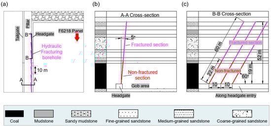
Figure 5.
The inclination (A-A) and strike (B-B) profile of fracturing drill holes. (a) layout of hydraulic fracturing borehole; (b) A-A cross-section; (c) B-B cross-section.
It is important to note the three specific requirements for fracturing:
- (1)
- Segmented single-hole fracturing in a retreating manner: fracturing is performed every 3 m, with the number of fracturing segments adjustable based on borehole inspection and rock mass strength. Fracturing should stop when reaching 10 m from the borehole opening. If abnormal sounds or extensive water inflow from the roof are observed, the fracturing operation should be stopped immediately.
- (2)
- Fracturing duration is set to 30 min and might be adjusted based on water pressure variation and roof water inflow.
- (3)
- Borehole construction and hydraulic fracturing should be carried out in parallel, with a spacing of no less than 40 m between them.
In this study, clear water was used as the fracturing fluid, which enabled effective fracture initiation and propagation under the geological and mining conditions. While fluid properties such as viscosity and sand content are known to influence fracture morphology and branching, this study focused primarily on fracturing design, monitoring, and field verification. The effect of fluid type on fracture propagation will be further investigated in future research.
3.3. Hydraulic Fracturing Effectiveness Verification
Borehole pressure cells (BPCs) are a mature and widely applied technique for measuring in situ stress in mining and geomechanics and have been used extensively worldwide, including in China, the USA, Europe, and Australia [36]. They were installed in pre-drilled boreholes by positioning the sensor at the target depth, securing it with low-shrinkage grout to ensure intimate contact with the surrounding rock, and routing the signal cables through protective conduits to the data acquisition system. After allowing adequate curing time for the grout, baseline readings were recorded. The sensors were calibrated prior to deployment, and their zero outputs were verified in the field under atmospheric conditions. Where applicable, selected cells were cross-checked against known loads. Calibration coefficients were then applied during data reduction to convert the measured output voltages into stress values, while periodic reference checks were used to monitor potential drift [37].
To verify the effectiveness of hydraulic fracturing, 14 sets of borehole pressure cells (BPCs) at varying depths (3 m to 27 m) were installed in the middle of both the F6218 headgate hydraulic fracturing test section and the corresponding unfractured comparison section. These BPCs were used to monitor stress changes within the coal pillar. The installation layout of the BPCs is shown in Figure 6a, while the on-site installation and operation of the ground pressure monitoring equipment are illustrated in Figure 6b. Figure 6c shows the cross-section of the F6225 tailgate entry with support system and monitor devices.
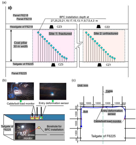
Figure 6.
On-site underground measurements for pillar stress, entry deformation, and cable/bolt load at both the F6218 headgate hydraulic fracturing test section and the corresponding unfractured comparison section. (a) layout of BPC in pillars; (b) installed BPC, cable/bolt load monitor, and entry deformation sensor; (c) cross-section of the tailgate of F6225.
Particularly, from Figure 6a, a total of 28 horizontal boreholes (diameter 48–50 mm) were drilled 1.5 m above the floor along the coal pillar side of the F6225 tailgate, with 14 boreholes in the hydraulic fracturing test section and 14 in the unfracturing section. In both sections, boreholes were spaced at 2 m intervals with depths ranging from 3 to 27 m, resulting in a total drilling length of 199 m per section.
In addition, four monitoring stations (CZ1–CZ4) were established in the hydraulic fracturing test area and the adjacent unfracturing area within the F6218 headgate and F6225 tailgate. CZ1 and CZ2 were located in the central part of the hydraulic fracturing zone, while CZ3 and CZ4 were positioned approximately 200 m from CZ1 and CZ2, respectively, in the unfractured area. Each station was equipped with three bolt dynamometers (installed at the roof and both ribs), one cable dynamometer at the roof center, and one entry deformation sensor.
It is important to note that the installation followed strict requirements: (1) the roof bolt and cable dynamometers were placed at the center of the roof and used support parameters consistent with actual support; (2) the rib bolt dynamometers were installed perpendicular to the ribs, 2.0–2.5 m above the floor, with parameters matching field conditions; and (3) the entry deformation sensor was installed at the roof center with a borehole depth of 8 m and a diameter of 28 mm, where the deep and shallow anchor points were set at 8 m and 2.5 m, respectively, and the spacing between the displacement sensor and the roof cable dynamometer was no more than 2 m in the strike direction. The total installation included 4 sets of cable dynamometers, 12 sets of bolt dynamometers, and 4 sets of entry deformation sensors, with a total borehole drilling length of 32 m (diameter 28 mm) for the entry deformation sensors.
4. Results
4.1. Hydraulic Water Pressure and Borehole Observation During Hydraulic Fracturing
China Coal Research Institute deployed a specialized underground hydraulic fracturing team at the Mine, equipped with professional drilling rigs and high-pressure pumps. The test involved a total drilling length of 1200 m, with 19 fracturing boreholes and a total fracturing footage of 1140 m. The pressure curves for the 19 fracturing boreholes (Series 1–19) monitored at the pump station during the fracturing process are shown in Figure 7a.
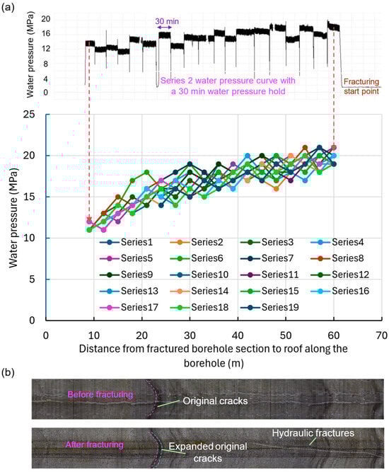
Figure 7.
Monitored water pressure variations and borehole observations before, after the hydraulic fracturing process. (a) water pressure curves at different borehole locations; (b) fractures on the borehole walls.
Taking the Series 2 borehole as an example, Figure 7a-top shows the water pressure during each stage of the hydraulic fracturing process. In accordance with the procedure described in Section 3.1, the water pressure was held for 30 min in each stage. The average pressure over this 30 min period was selected to represent the water pressure for that specific fracturing segment. These selected values, along with their corresponding locations—defined as the distance from the fractured borehole segment to the roof level along the borehole—are presented in Figure 7a-bottom. A total of 19 segments are included, each representing a separate stage of the hydraulic fracturing process. Based on these average pressure values, the results indicate that the water pressure stabilized at approximately 15–20 MPa when fracturing occurred within the roof strata (20–60 m) and remained below 15 MPa when fracturing took place within the coal seam (10–20 m).
In addition, using the Series 2 borehole as an example, borehole imaging was performed both before and after hydraulic fracturing. The observed fractures can be categorized into three types: original fractures, expanded original fractures, and hydraulic fractures (Table 3). Original fractures were observed at various depths along the borehole. Hydraulic fractures were primarily concentrated in the coal-bearing strata between 15 and 17 m, while expanded original fractures were mainly distributed at depths of 10 m and 24–28 m, within the coal-bearing layers and carbonaceous mudstone. Furthermore, no significant fracture development was observed in the upper sandstone roof before or after hydraulic fracturing, indicating high rock integrity. Figure 7b illustrates typical features of the three fracture types. Importantly, the borehole imaging confirms the formation of new hydraulic fractures and the expansion of pre-existing fractures within the roof strata. These developments demonstrate that permeability was effectively enhanced. The new fractures, induced by high-pressure water injection, not only increase fracture conductivity for gas drainage but also weaken the hard roof strata, thereby reducing the risk of sudden roof break and the associated strong ground pressure.
Table 3.
Fracture development observed via borehole camera in Series 2 boreholes.
Based on the above analysis, hydraulic fracturing effectively induced and expanded fractures within the 0–30 m roof interval, particularly in mudstone and sandy mudstone, where lower strength and higher brittleness facilitated crack propagation and connectivity. This contributed significantly to roof weakening and stress relief. In contrast, the high-level sandstone roof (above 30 m) displayed greater hardness and structural integrity, which required higher fracturing pressures and resulted in only limited fracture development. Nevertheless, minor fractures were still generated in these sandstone layers, indicating that even strong, competent strata could be partially disturbed by hydraulic fracturing. Importantly, after panel excavation, no severe ground pressure manifestations were observed, demonstrating that the overall fracturing process successfully weakened the composite roof structure and reduced the risk of dynamic pressure events. While the present study primarily emphasizes fracture development, a more quantitative analysis of the relationship between rock mechanical parameters and fracturing parameters (e.g., pressure, duration) will be undertaken in future research to further refine the understanding of high-level strata fracturing behavior.
4.2. Underground Measurements Results Before and After Hydraulic Fracturing
4.2.1. Coal Pillar Vertical Stress
Figure 8 presents the vertical stress concentration coefficients—defined as the ratio of peak stress to initial stress—within coal pillars in both the fractured and unfractured (normal) sections. The fractured section exhibits significantly lower stress concentration coefficients compared to the unfractured section, reflecting a more favorable stress distribution. Notably, the location of peak stress shifts deeper into the coal pillar after fracturing, moving from approximately 9 m to 11 m from the edge. This shift indicates a redistribution of stress away from the pillar boundaries. Furthermore, the width of the elastic core zone in the central portion of the coal pillar increases from about 7 m to 11 m, suggesting enhanced pillar stability and a more effective load-bearing capacity due to the fracturing treatment.

Figure 8.
Coal pillar stress before and after hydraulic fracturing. (Stress concentration coefficient represents the ratio of current stress to initial stress).
4.2.2. Entry Deformation
The entry deformation consists primarily of two components: rib-to-rib convergence and roof-to-floor convergence. Prior to pressure relief (fracturing), significant deformation was observed, including notable floor heave, as illustrated in Figure 9a. In particular, Figure 9b shows that the maximum rib convergence reached approximately 400 mm (marked by the red dashed line), while the maximum roof-to-floor convergence was about 520 mm (dark blue dashed line).
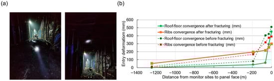
Figure 9.
Entry deformation before and after hydraulic fracturing. (a) field photo; (b) entry deformation with different panel face locations.
After implementing the pressure relief measures, although deformation continued to increase as the entry approached the longwall face, the magnitude of deformation was notably reduced. Specifically, the maximum rib convergence decreased to approximately 300 mm (orange solid line), and the roof-to-floor convergence was reduced to around 450 mm (green solid line). Additionally, floor heave was effectively mitigated and no longer impeded normal production operations.
In summary, compared to the conventional mining section without pressure relief, the rib deformation was reduced by 25% (from 400 mm to 300 mm), and the roof-to-floor convergence was reduced by 13.5% (from 520 mm to 450 mm). These results demonstrate that the pressure relief approach achieved a moderate but meaningful reduction in overall entry deformation, contributing to improved stability and safer working conditions.
4.2.3. Cable/Bolt Load
Figure 10 illustrates the loading conditions of roof bolts and cable bolts before and after fracturing. Monitoring commenced roughly 280 m ahead of the advancing longwall face and continued for three months after the face passed the instrumentation sites. Throughout this monitoring period, the support loads remained generally stable, exhibiting only minor local fluctuations. This stability in support loading indicates that the roof and ribs of the return airway—excavated next to a previously mined panel with a 30 m wide coal pillar—maintained overall structural integrity during panel extraction. These findings suggest that the coal pillar design, combined with the implemented support system, effectively ensured ground stability under dynamic mining conditions.
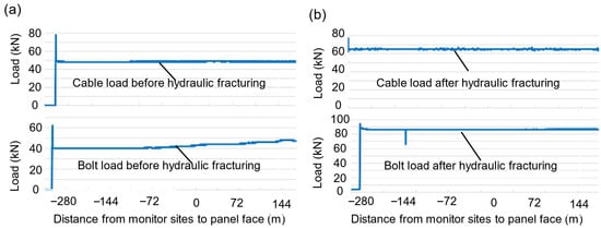
Figure 10.
Cable/bolt load before and after hydraulic fracturing. (a) cable and bolt load before hydraulic fracturing; (b) cable and bolt load after hydraulic fracturing.
4.3. Summary of Underground Measurements Results
The above underground monitoring was conducted to evaluate the effectiveness of hydraulic fracturing in controlling stress redistribution and maintaining entry stability under a 30 m wide coal pillar. Roof bolt and cable bolt loadings were recorded starting approximately 280 m ahead of the advancing longwall face and continued for three months after the face passed the monitoring site. The data showed that the support loads remained generally stable, with only minor local fluctuations throughout the monitoring period.
These results indicate that the roof and ribs of the return airway—developed adjacent to a previously mined panel—remained in a stable condition both before and after hydraulic fracturing. More importantly, the hydraulic fracturing operation effectively reduced stress concentrations in the coal pillar, without compromising the stability of the entry.
This outcome suggests that the current 30 m wide coal pillar may be more conservative than necessary, particularly when hydraulic fracturing is applied to manage stress conditions. Therefore, it raises the possibility of optimizing pillar dimensions—potentially reducing pillar width—while still maintaining safe and stable mining conditions.
The next section will review typical pillar sizes used internationally and in China, including relevant case studies. This will help assess whether the pillar width can be safely reduced, and to what extent, when hydraulic fracturing is used as a stress-relief method.
5. Discussion on Pillar Size Optimization
5.1. Pillar Stress Monitoring Results in Different Countries
Zhao et al. (2022) [38] reviewed pillar stress changes from global studies on longwall mining. The results showed that despite differences in measurement methods and geological settings, a consistent three-stage stress evolution trend was observed: (1) an initial slow and steady stress increase, (2) a rapid stress increase, and (3) a peak stress followed by a gradual or rapid decline. These trends were observed in pillar stresses, abutment pressures, and support loads, offering valuable references for comparison in similar projects. Particularly, there were three cases about pillar stress responses from three international mines—located in Japan (Mine A), the USA (Mine B), and Canada (Mine C)—with relevant pillar dimensions and mining conditions (see Table 4). The pillar stress curves are shown in Figure 11.
Table 4.
Geological and mining conditions of Mines A to C.
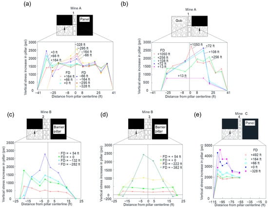
Figure 11.
Stress distribution across Pillar 1 in Mine A, Pillar 2 and 3 in Mine B, and Pillar 4 in Mine C [38]. (a) first panel mining at Mine A; (b) second panel mining at Mine A; (c) first panel mining at Mine B; (d) first panel mining at Mine B; (e) first panel mining at Mine C.
In Mine A, the pillar was 25 m wide. As the first panel approached the monitoring site (Figure 11a), stress increased sharply near the pillar edge (within 9 ft (0.3 m)). After facing passage, the peak stress moved toward the center of the pillar, suggesting yield development near the edge and eventual formation of a stable pillar core (Figure 11). As the second panel advanced, stress gradually decreased across the pillar, indicating that the yield zone spread across the entire pillar. Since the pillar was expected to become part of the gob after the second panel, this yielding behavior was considered acceptable, confirming that a 25 m pillar maintained stability throughout the extraction process.
In contrast, Mine B had a pillar width of only 13 m. Monitoring data revealed excessive stress concentration near the center of the pillar (nearly 3000 psi (20.7 MPa)), and early failure was recorded at the pillar edge (Figure 11c,d). These stress patterns indicated instability and insufficient size, making the 13 m width inadequate for longwall mining. Conversely, Mine C used a much wider pillar of 35 m. Stressmeters recorded a moderate and stable increase in stress across the pillar as the face approached, with little variation even near the edge (Figure 11e). This suggested that the 35 m pillar was overly conservative, maintaining very high stability but likely leading to unnecessary coal loss.
Overall, these international case studies imply that pillar widths below 20 m can be unstable, while those over 30–35 m may be overly conservative. The 25 m pillar in Mine A provided a balance between stability and resource recovery, supporting the premise that a similar pillar width could be an optimized choice—especially when combined with hydraulic fracturing to reduce pillar stress. This evidence aligns well with the underground measurements at Buliangou Mine, reinforcing the feasibility of reducing the coal pillar width from 30 m to around 25 m while maintaining entry stability.
5.2. Pillar Size in Similar Geological Conditions in China
A review of coal pillar retention practices in ultra-thick coal seam longwall mining across China reveals that district coal pillars are generally maintained at widths greater than 20 m (see Table 5). However, due to varying geological and mining conditions, the performance of these pillars differs significantly between mines. For example, stable entry conditions have been achieved with 20–21 m wide pillars at Xiegou and Tangjiahui Mines. In contrast, operations at Jinzhuang, Suancigou, and Luzigou Mines required 30 m wide pillars to maintain entry stability. Notably, Luzigou Mine experienced severe entry deformation even with 30 m wide pillars, mainly due to complex geology and cumulative stress from repeated mining.
Table 5.
Successful determination of pillar widths in fully mechanized top-coal caving faces of ultra-thick coal seams in China.
In comparison, for this study area, Buliangou Mine operates under relatively simple geological conditions and mines the 6# seam using the longwall top coal caving method, with an average seam thickness exceeding 16 m. Mines such as Suancigou and Tangjiahui—with similar seam characteristics—provide useful benchmarks. At Suancigou, field experience shows that 24–26 m wide pillars, in combination with pressure relief measures, can maintain entry stability. Tangjiahui Mine demonstrates that even 21 m wide pillars can be sufficient under favorable geological conditions.
By analogy, and supported by field measurements at Buliangou Mine, the currently adopted 30 m coal pillar width may be overly conservative. Considering the observed reduction in coal pillar stress and entry deformation achieved through hydraulic fracturing, it is preliminarily concluded that a pillar width reduction to approximately 25–26 m is feasible without compromising entry stability. Comparisons with similar mines reinforce this conclusion, particularly when lateral stress is effectively managed via hydraulic fracturing.
Therefore, for Buliangou Mine—with its relatively straightforward roof and geological conditions—it is recommended to optimize the pillar width to approximately 25–26 m. This approach strikes a balance between maintaining entry stability and improving coal recovery, offering a significant economic advantage. Importantly, this recommendation is predicated on the continued application of hydraulic fracturing to control lateral stress and enhance coal pillar performance.
It is important to note that the borehole spacing (10 m), inclination (5°), and fracturing time (30 min) used in this study were selected based on the geological conditions and operational constraints of the F6221 panel. Although these parameters proved effective in weakening the roof and reducing stress concentrations, their sensitivity to variations (e.g., 8–12 m spacing or different borehole inclinations) was not systematically analyzed. Further experimental and numerical studies are needed to quantify the influence of these parameters on fracture network development and stress relief effectiveness, which will be the focus of future research.
The following section presents an industrial-scale field verification using a 26 m-wide pillar and hydraulic fracturing in a new longwall panel at Buliangou Mine, aimed at confirming the effectiveness and safety of this optimization strategy.
6. Verification of Pillar Size Optimization
To validate the safety and effectiveness of the proposed pillar width optimization strategy—based on hydraulic fracturing for pressure relief—a field application was conducted in the F6221 longwall panel, located on the eastern wing of the second mining district at Buliangou Coal Mine. In this panel, the coal pillar width was reduced to 26 m from the conventional 30 m between adjacent gateroads.
The F6221 panel is mined at a depth of 273.6–323.3 m, with a face width of 250.8 m and a strike length of 1389 m. The average coal seam thickness is 19.8 m, including 4.0 m of interbedded partings mainly distributed in the middle and upper portions of the seam. The seam has a dip ranging from 0° to 9°, averaging 5°, and exhibits stable roof and floor conditions. Entry has a cross-section of 5.5 m by 4.0 m and are supported by 16 fully grouted rebar bolts and pre-tensioned cable bolts (Φ21.8 mm, L = 8 m) in a rectangular layout.
As a pre-mining measure, hydraulic fracturing was carried out in the entry of the adjacent F6220 panel, targeting the roof near the F6221 headgate entry. This pressure relief allowed the use of a narrower 26 m pillar without modifying the original support design. A monitoring station was installed to evaluate the entry’s deformation response during mining.
Throughout the full 1389 m retreat length, the maximum deformation observed in the F6221 headgate entry was 300 mm in rib displacement and 400 mm in roof-floor convergence (Figure 12). These deformations were mainly confined to the zone within 60 m ahead of the face and remained within acceptable limits, posing no impact on longwall operations. Ten instrumented bolts were installed to monitor support performance. Most bolts displayed a typical “gradual increase–stabilization” load trend as mining progressed. Four bolts exhibited higher stress gains (33–66 kN), with peak loads of 100–114 kN. Considering the design capacity of the Φ22 mm rebar bolts is 156 kN, all bolts operated within 64–73% of their limit, indicating adequate support performance and a strong safety margin.
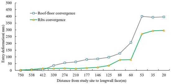
Figure 12.
Entry deformation after hydraulic fracturing.
The successful field application demonstrated that a 26 m-wide pillar, when combined with pre-mining hydraulic fracturing, provided sufficient stability while significantly enhancing coal recovery. This optimization strategy reduced in situ coal loss within the pillar zone, improved resource utilization, and contributed to extending the mine’s operational life. During the one-year trial, approximately 100,000 tons of additional coal were recovered from the F6221 panel. It is important to note that long-term monitoring (3–5 years), particularly under the influence of subsequent adjacent panel mining, is necessary to evaluate the secondary stress disturbance on the 26 m pillar and to verify the long-term reliability of the optimized scheme. We will continue stress and deformation monitoring as mining advances, and plan to supplement and analyze multi-panel disturbance data in our future work.
This hydraulic fracturing–assisted pillar optimization approach not only improves economic outcomes but also aligns with the principles of green, efficient, and intelligent mining. It offers a technically robust and replicable method for reducing overly conservative pillar designs while maintaining entry stability and production continuity. The success of this trial supports broader application across other panels in Buliangou Mine and highlights its potential scalability to other ultra-thick seam longwall operations in China. Furthermore, the method represents a patentable innovation, marking a meaningful advancement in underground mine design.
However, it is important to note that pillar size optimization must be guided by detailed, site-specific assessments. Continuous monitoring of pillar stress, entry deformation, and support loading is essential to ensure long-term stability throughout mining operations. Future work may focus on refining fracturing parameters and improving monitoring protocols to further optimize pillar design and maximize resource recovery.
In addition, it should be noted that this study was conducted in a relatively flat coal seam (dip angle ~4°) without complex faults. In coal seams with larger dip angles or strong tectonic disturbances, gravity and in situ stress anisotropy may affect fracture propagation and roof weakening effectiveness. Under such conditions, dip angle or stress correction factors may need to be considered in pillar width optimization, which will be addressed in future studies.
This study primarily focused on pillar width optimization and hydraulic fracturing effects. The entry support system was applied according to existing mine standards and was not optimized in conjunction with fracturing. Future research should consider the coupling among fracturing parameters, pillar stress, and support load, with the aim of developing an integrated optimization framework to further enhance both technical reliability and economic efficiency.
7. Discussion
This study demonstrates that targeted hydraulic fracturing, combined with detailed field monitoring, is a practical and effective method for optimizing coal pillar dimensions in ultra-thick seam longwall mining. The proposed approach enabled controlled roof weakening and stress redistribution, resulting in reduced entry deformation and a wider elastic core zone within the pillar. Field instrumentation, including borehole imaging, water pressure monitoring, and stress/strain sensors, provided direct evidence of fracture propagation, expansion of pre-existing fractures, and a measurable reduction in peak pillar stress. The successful implementation of a 26 m-wide pillar in the F6221 panel confirmed that hydraulic fracturing can balance entry stability and coal recovery, achieving both technical and economic improvements, with an additional 100,000 tons of coal recovered during the one-year monitoring period. Although a direct comparison with other fracturing methods was not conducted, these results indicate that the applied method effectively improved resource utilization while maintaining roof and pillar stability.
A major strength of this study is its integration of design, monitoring, and field verification, which provides a reproducible framework for other ultra-thick seam operations. The staged multi-interval fracturing from angled boreholes was effective in forming fracture networks in weaker strata (mudstone and sandy mudstone) and even induced minor fractures in harder sandstone layers, contributing to overall roof weakening. This combination of empirical field data and engineering design represents a significant advancement over purely numerical or theoretical studies and provides practical guidance for similar mines in China and internationally.
Despite these successes, several limitations should be acknowledged. First, the study was conducted in a relatively gentle coal seam dip (~4°) with minimal faulting, so the influence of larger dip angles or complex tectonic stresses on fracture propagation and pillar stability remains unquantified. Second, the sensitivity of fracturing parameters (borehole spacing, inclination, fracturing pressure) was not systematically analyzed; variations in these parameters could affect fracture density and stress relief effectiveness. Third, the study focused on pillar optimization and roof weakening, while integrated optimization with the entry support system (e.g., bolt pre-tension adjustment) was not explored. Finally, only one year of monitoring data is currently available; longer-term multi-panel mining effects on pillar stress and entry deformation will require continued observation to validate long-term stability and economic benefits.
The proposed hydraulic fracturing method is potentially applicable to other CBM reservoirs with similar geological conditions. Site-specific evaluation is required to determine appropriate operational parameters, including borehole spacing, inclination, fracturing pressure, and monitoring strategies, which should be adapted according to local geology, in situ stress, and seam characteristics to ensure optimal performance.
Future research should address these limitations by incorporating numerical modeling and extended field trials to explore: (1) the influence of seam dip, faulting, and tectonic stress on fracture propagation; (2) parameter sensitivity analysis for fracturing design; and (3) coupled optimization of fracturing, pillar dimensions, and support systems to further improve operational efficiency and safety. Overall, this study provides a practical, field-verified methodology to guide hydraulic fracturing applications for pillar optimization in ultra-thick coal seam longwall operations, with potential applicability to other CBM reservoirs and mining sites with similar geological conditions.
8. Conclusions
This study demonstrated the feasibility and effectiveness of optimizing coal pillar dimensions in ultra-thick seam longwall mining through a combination of hydraulic fracturing and on-site monitoring. Key conclusions are as follows:
- (1)
- This study successfully introduced a targeted hydraulic fracturing methodology to improve stress redistribution and roof weakening in underground coal mining. A detailed plan was implemented in the F6218 headgate entry, involving 60 m-long boreholes angled 5° toward the gob and spaced at 10 m intervals. A staged, multi-interval fracturing scheme was adopted, achieving stable fracturing pressures of ~20 MPa in the roof and <15 MPa in the coal seam. Borehole imaging and field monitoring confirmed the generation of effective fracture networks within the 0–30 m roof zone and demonstrated a clear reduction in stress concentration and entry deformation.
- (2)
- Drawing on the field outcomes from the fracturing trial, and referencing both domestic and international longwall mining practices, a 26 m-wide coal pillar was identified as the optimal dimension under pressure-relieved conditions. This width strikes a balance between maintaining entry and pillar stability while enhancing coal resource recovery. Comparative engineering analyses suggested that reducing pillar size from conventional widths is feasible when combined with appropriate fracturing and monitoring strategies.
- (3)
- The 26 m-wide pillar design was successfully applied in the F6221 panel, supported by continuous geomechanical monitoring. Results showed improved coal pillar integrity, increased width of the elastic core, reduced entry deformation, and stable support performance. Over the one-year implementation, approximately 100,000 tons of additional coal were recovered, validating the economic and technical viability of this optimization strategy. The approach is now considered technically sound for broader application within Buliangou Mine and potentially across other ultra-thick seam operations in China.
Author Contributions
Conceptualization, Z.L., G.X. and G.Z.; Methodology, Z.L., G.X., Z.Z. and G.Z.; Investigation, Z.L., G.X., Z.Z. and G.Z.; Writing—original draft, Z.L. and G.Z.; Writing—review and editing, G.X., Z.Z. and G.Z.; Project administration, Z.L. All authors have read and agreed to the published version of the manuscript.
Funding
This research was funded by the Science and Technology Innovation and Entrepreneurship Fund of Tiandi Science and Technology Co., Ltd. in China, grant number “No. 2023-2-TD-ZD003” and the Natural Science Foundation of Hebei Province, China, grant number “No. E2023508026”.
Data Availability Statement
The data presented in this study are available on request from the corresponding author due to the large size and complexity of the datasets.
Conflicts of Interest
Authors Zhengjie Li, Gang Xu and Zhen Zhang were employed by Mining Research Institute, China Coal Research Institute and Coal Mining Research Institute Co., Ltd. Author Gaobo Zhao was employed by RESPEC LLC.
References
- Hubbert, M.K.; Willis, D.G. Mechanics of Hydraulic Fracturing. Trans. AIME 1957, 210, 153–168. [Google Scholar] [CrossRef]
- Montgomery, C.T.; Smith, M.B. Hydraulic Fracturing: History of an Enduring Technology. J. Pet. Technol. 2010, 62, 26–40. [Google Scholar] [CrossRef]
- Pan, X.P.; Zhang, G.Z.; Chen, J.J. The Construction of Shale Rock Physics Model and Brittleness Prediction for High-Porosity Shale Gas-Bearing Reservoir. Pet. Sci. 2020, 17, 658–670. [Google Scholar] [CrossRef]
- Zhu, Y.; Xu, S.; Payne, M.; Martinez, A.; Liu, E.; Harris, C.; Bandyopadhyay, K. Improved Rock-Physics Model for Shale Gas Reservoirs. In Proceedings of the Society of Exploration Geophysicists International Exposition and 82nd Annual Meeting 2012, SEG 2012, Las Vegas, NV, USA, 4–9 November 2012; pp. 2439–2443. [Google Scholar] [CrossRef]
- Kim, J.; Moridis, G.J. Numerical Analysis of Fracture Propagation during Hydraulic Fracturing Operations in Shale Gas Systems. Int. J. Rock Mech. Min. Sci. 2015, 76, 127–137. [Google Scholar] [CrossRef]
- He, Q.; Suorineni, F.T.; Oh, J. Review of Hydraulic Fracturing for Preconditioning in Cave Mining. Rock Mech. Rock Eng. 2016, 49, 4893–4910. [Google Scholar] [CrossRef]
- HAIMSON, B.C. The Hydraulic Fracturing Method of Stress Measurement: Theory and Practice. In Rock Testing and Site Characterization; Elsevier: Amsterdam, The Netherlands, 1993; pp. 395–412. [Google Scholar]
- Jeffrey, R.G.; Mills, K.W. Hydraulic Fracturing Applied to Inducing Longwall Coal Mine Goaf Falls. In Proceedings of the ARMA North America Rock Mechanics Symposium, Seattle, WA, USA, 31 July–3 August 2000; ARMA: Alexandria, VA, USA, 2000; p. ARMA-2000. [Google Scholar]
- Kang, H.; Lv, H.; Gao, F.; Meng, X.; Feng, Y. Understanding Mechanisms of Destressing Mining-Induced Stresses Using Hydraulic Fracturing. Int. J. Coal Geol. 2018, 196, 19–28. [Google Scholar] [CrossRef]
- Zhang, Q.; He, M.; Wang, J.; Guo, S.; Wang, C.; Hong, C.; Chen, K.; Yang, R.; Zhang, X.; Yang, J. Non-Explosive Directional Fracturing Blasting Using Coal-Based Solid Waste Expanding Agent. J. Rock Mech. Geotech. Eng. 2025, 17, 3691–3710. [Google Scholar] [CrossRef]
- Xia, B.; Ma, Z.; Zhou, L.; Zhou, Y.; Li, Y. Decoding the Hard Roof Control Mechanism of Ground Fracturing Based on the Material Point Method. Rock Mech. Rock Eng. 2025, 58, 8721–8736. [Google Scholar] [CrossRef]
- Zou, J.; Zhang, Q.; Jiang, Y.; Jiao, Y.-Y.; Zhu, S.; Zhang, G. Mechanism of Hydraulic Fracturing for Controlling Strong Mining-Induced Earthquakes Induced by Coal Mining. Int. J. Rock Mech. Min. Sci. 2024, 181, 105840. [Google Scholar] [CrossRef]
- Zoback, M.D.; Haimson, B.C. Status of the Hydraulic Fracturing Method for In-Situ Stress Measurements. In Proceedings of the ARMA US Rock Mechanics/Geomechanics Symposium, Berkeley, CA, USA, 25–27 August 1982; ARMA: Alexandria, VA, USA, 1982; p. ARMA-82. [Google Scholar]
- Sone, H. Mechanical Properties of Shale Gas Reservoir Rocks and Its Relation to the In-Situ Stress Variation Observed in Shale Gas Reservoirs. Ph.D. Thesis, Stanford University, Palo Alto, CA, USA, 2012. [Google Scholar]
- Osiptsov, A.A. Fluid Mechanics of Hydraulic Fracturing: A Review. J. Pet. Sci. Eng. 2017, 156, 513–535. [Google Scholar] [CrossRef]
- Rummel, F. Fracture Mechanics Approach to Hydraulic Fracturing Stress Measurements. Fract. Mech. Rock 1987, 217, 221–245. [Google Scholar]
- Huang, B.; Wang, Y.; Cao, S. Cavability Control by Hydraulic Fracturing for Top Coal Caving in Hard Thick Coal Seams. Int. J. Rock Mech. Min. Sci. 2015, 74, 45–57. [Google Scholar] [CrossRef]
- Anderson, I.; Ma, J.; Wu, X.; Stow, D. Determining Reservoir Intervals in the Bowland Shale Using Petrophysics and Rock Physics Models. Geophys. J. Int. 2022, 228, 39–65. [Google Scholar] [CrossRef]
- Abe, A.; Horne, R.N. Investigating Stress Shadowing Effects and Fracture Propagation Patterns: Implications for Enhanced Geothermal Reservoirs. Int. J. Rock Mech. Min. Sci. 2021, 142, 104761. [Google Scholar] [CrossRef]
- Hashemi, S.S.; Zoback, M.D. Effect of Supercritical CO2 on Permeability and Surface Characteristics of Fractures in Shales. In Proceedings of the 56th US Rock Mechanics/Geomechanics Symposium, Santa Fe, NM, USA, 26–29 June 2022. [Google Scholar] [CrossRef]
- Kang, H.; Yang, J.; Meng, X. Tests and Analysis of Mechanical Behaviours of Rock Bolt Components for China’s Coal Mine Roadways. J. Rock Mech. Geotech. Eng. 2015, 7, 14–26. [Google Scholar] [CrossRef]
- Kang, H.; Wu, Y.; Gao, F. Deformation Characteristics and Reinforcement Technology for Entry Subjected to Mining-Induced Stresses. J. Rock Mech. Geotech. Eng. 2011, 3, 207–219. [Google Scholar] [CrossRef]
- Li, Y.; Dai, X.; Yang, R.; Zhu, Y.; Li, R.; Zhou, C.; Xie, L.; Li, W. Failure Mechanism and Support Technology of Weakly Cemented Soft Rock Roadway in Water-Rich Environment. Geotech. Geol. Eng. 2025, 43, 213. [Google Scholar] [CrossRef]
- Huang, B.-X.; Yu, B.; Feng, F.; Li, Z.; Wang, Y.-Z.; Liu, J.-R. Field Investigation into Directional Hydraulic Fracturing for Hard Roof in Tashan Coal Mine. J. Coal Sci. Eng. 2013, 19, 153–159. [Google Scholar] [CrossRef]
- Fan, J.; Dou, L.; He, H.; Du, T.; Zhang, S.; Gui, B.; Sun, X. Directional Hydraulic Fracturing to Control Hard-Roof Rockburst in Coal Mines. Int. J. Min. Sci. Technol. 2012, 22, 177–181. [Google Scholar] [CrossRef]
- Liu, J.; Liu, C.; Yao, Q.; Si, G. The Position of Hydraulic Fracturing to Initiate Vertical Fractures in Hard Hanging Roof for Stress Relief. Int. J. Rock Mech. Min. Sci. 2020, 132, 104328. [Google Scholar] [CrossRef]
- Kang, H.; Feng, Y.; Zhang, Z.; Zhao, K.; Wang, P. Hydraulic Fracturing Technology with Directional Boreholes for Strata Control in Underground Coal Mines and Its Application. Coal Sci. Technol. 2023, 51, 31–44. [Google Scholar]
- Kang, H.; Jiang, P.; Feng, Y.; Gao, F.; Zhang, Z.; Liu, X. Application of Large-Scale Hydraulic Fracturing for Reducing Mining-Induced Stress and Microseismic Events: A Comprehensive Case Study. Rock Mech. Rock Eng. 2023, 56, 1399–1413. [Google Scholar] [CrossRef]
- Kang, H.; Xia, Y.; Feng, M.; Lu, C.; Gao, F. Case Study of Hydraulic Fracturing for Coal Burst Risk Mitigation. Int. J. Coal Sci. Technol. 2025, 12, 61. [Google Scholar] [CrossRef]
- Kang, H.; Gao, F.; Xu, G.; Ren, H. Mechanical Behaviors of Coal Measures and Ground Control Technologies for China’s Deep Coal Mines—A Review. J. Rock Mech. Geotech. Eng. 2023, 15, 37–65. [Google Scholar] [CrossRef]
- Huang, B.; Liu, J.; Zhang, Q. The Reasonable Breaking Location of Overhanging Hard Roof for Directional Hydraulic Fracturing to Control Strong Strata Behaviors of Gob-Side Entry. Int. J. Rock Mech. Min. Sci. 2018, 103, 1–11. [Google Scholar] [CrossRef]
- Ma, Z.; Xia, B.; Zhou, L.; Zhou, Y.; Li, Y. Influence of Hydraulic Fracture Parameters on Hard Roof Control Using MPM with Jaumann Stress Rate. Int. J. Geomech. 2025, 25, 04025171. [Google Scholar] [CrossRef]
- Wang, X.; Feng, Y.; Zhang, F.; Zhao, K.; Yin, Z. Investigation on Breakage and Collapse Characteristics of Hard and Thick Roof during Coal Excavation Subject to Hydraulic Fracturing. Eng. Fail. Anal. 2025, 181, 109935. [Google Scholar] [CrossRef]
- Shao, L.; Huang, B.; Chen, S.; Li, H.; Zhao, X. Hydraulic Fracturing Control of the Hard Roof During Horizontal Slicing Fully Mechanized Top Coal Caving Mining in Steep Thick Coal Seam. Min. Met. Explor. 2025, 42, 1727–1739. [Google Scholar] [CrossRef]
- Wang, J.; Wei, W.; Zhang, J. Effect of the Size Distribution of Granular Top Coal on the Drawing Mechanism in LTCC. Granul. Matter 2019, 21, 70. [Google Scholar] [CrossRef]
- Peng, S.S.; Cheng, J.; Du, F.; Xue, Y. Underground Ground Control Monitoring and Interpretation, and Numerical Modeling, and Shield Capacity Design. Int. J. Min. Sci. Technol. 2019, 29, 79–85. [Google Scholar] [CrossRef]
- Lu, P.H. Mining-Induced Stress Measurement with Hydraulic Borehole Pressure Cells. In Proceedings of the ARMA US Rock Mechanics/Geomechanics Symposium, Evanston, IL, USA, 25–27 June 1984; ARMA: Alexandria, VA, USA, 1984; p. ARMA-84. [Google Scholar]
- Zhao, G.; Tulu, I.B.; Peng, S.S.; Tuncay, D. Characteristics of Abutment Pressures and Bolt Loads in Longwall System: A Review on Stress/Load Measurements. In Proceedings of the 41st International Conference on Ground Control in Mining, ICGCM 2022, Canonsburg, PA, USA, 26–28 July 2022; pp. 109–121. [Google Scholar]
- Matsui, K.; Ichinose, M.; Uchino, K. Stability of Interpanel-Pillar and Deformation of Gateroad Due to Longwall Mining. In Proceedings of the 10th International Conference on Ground Control in Mining, ICGCM 1991, Morgantown, WV, USA, 26–28 July 1991; pp. 43–51. [Google Scholar]
- Mark, C.; Bieniawski. Field Measurements of Chain Pillar Response to Longwall Abutment Loads. Mark, C. and Z.T. Bieniawski. Field Measure-ments of Chain Pillar Response to Longwall Abutment Loads. In Proceedings of the 5th International Conference on Ground Control in Mining, ICGCM 1986, Morgantown, WV, USA, 26–28 July 1986; pp. 114–122. [Google Scholar]
- Payne, D.; DeMarco, M. Vertical Stress Redistribution around a Retreating Longwall Face End. In Proceedings of the 14th International Conference on Ground Control in Mining, ICGCM 1995, Morgantown, WV, USA, 26–28 July 1995; pp. 273–283. [Google Scholar]
Disclaimer/Publisher’s Note: The statements, opinions and data contained in all publications are solely those of the individual author(s) and contributor(s) and not of MDPI and/or the editor(s). MDPI and/or the editor(s) disclaim responsibility for any injury to people or property resulting from any ideas, methods, instructions or products referred to in the content. |
© 2025 by the authors. Licensee MDPI, Basel, Switzerland. This article is an open access article distributed under the terms and conditions of the Creative Commons Attribution (CC BY) license (https://creativecommons.org/licenses/by/4.0/).