Abstract
With the growing demand for high-efficiency and high-performance electric motors in applications such as electric vehicles, drones, and industrial drive systems, Axial Flux Motors (AFMs) have gained significant attention due to their high torque density and compact structure. However, low-pole AFMs are prone to performance degradation and noise issues caused by magnetic saturation in the rotor back yoke and increased torque ripple. In this study, a conventional 6-pole, 9-slot Radial Flux Motor (RFM) was redesigned as an AFM within the same external volume. To minimize losses, the stator inner diameter and slot thickness were co-optimized. In addition, tapering techniques were applied to both the stator and magnets to reduce torque ripple, and a parametric analysis of magnet tapering was conducted to identify optimal design conditions. A rolling core fabrication method was adopted to ensure both electromagnetic performance and manufacturability. The final AFM design demonstrated a 1.4 percentage point improvement in efficiency. Additionally, torque ripple was reduced by 69.44%, thereby validating the effectiveness of the AFM redesign and ripple reduction strategy.
Keywords:
motor; axial flux motor; pump motor; torque ripple; cogging torque; tapering; core loss; copper loss; AFM 1. Introduction
The use of Permanent Magnet Synchronous Motors (PMSMs) is rapidly expanding across various industrial sectors that demand high efficiency and high performance [1,2]. PMSMs can be broadly classified into Radial Flux Motors (RFMs) and Axial Flux Motors (AFMs) based on the direction of magnetic flux. Among them, AFMs have recently received significant attention due to their ability to achieve higher torque density compared to conventional RFMs [3,4,5]. Due to their structural and magnetic characteristics, AFMs typically adopt a multipole configuration. When the number of poles is low, magnetic saturation tends to intensify in the rotor back yoke, leading to increased core losses and torque ripple. Assuming the same outer dimensions, a lower pole count results in a larger amount of magnetic flux transitioning from the N-pole to the S-pole, which increases magnetic saturation in the back yoke. In contrast, a higher pole count reduces the flux per magnet, thereby mitigating saturation [6,7]. Although a multipole structure effectively alleviates magnetic saturation, it increases control complexity and may introduce additional losses. Therefore, selecting an appropriate number of poles is a critical factor for optimizing AFM performance. In this study, an AFM design with a low pole count is proposed. A 6-pole, 9-slot RFM was selected as the baseline model and was redesigned as an AFM within the same physical volume. One of the key considerations during the RFM-to-AFM conversion is the determination of the stator inner diameter. Simply applying the same inner diameter as the original RFM may significantly limit the design freedom of the AFM and hinder optimal performance. The inner diameter directly affects the coil length, which in turn influences copper losses. However, excessively increasing the inner diameter to reduce copper losses can reduce the number of usable magnets, resulting in a lower magnetic flux density and magnetic loading ratio, thereby degrading overall motor performance. Therefore, to enhance output and efficiency, it is essential to determine an appropriate inner diameter that optimizes the magnetic loading ratio. Additionally, AFMs with a low pole count are prone to increased torque ripple due to magnetic saturation in the rotor back yoke and other electromagnetic factors. This necessitates the application of torque ripple reduction strategies. In this study, tapering techniques were applied to both the stator and magnets to reduce torque ripple [8,9,10], and a prototype was fabricated to validate the effectiveness of the proposed design. Unlike RFMs, AFMs face geometric constraints that make it difficult to apply conventional laminated steel sheets. As a result, AFMs are often fabricated using soft magnetic composites (SMC) or solid cores. In this research, however, a rolling core approach—where laminated steel sheets are wound according to the flux direction—was adopted to ensure both high electromagnetic performance and manufacturability. Ultimately, the RFM was successfully redesigned into an AFM using the same external volume and a low pole count configuration. Under identical output conditions, the proposed AFM design demonstrated improved efficiency and significantly reduced torque ripple, confirming the effectiveness of the redesign approach.
2. Materials and Methods
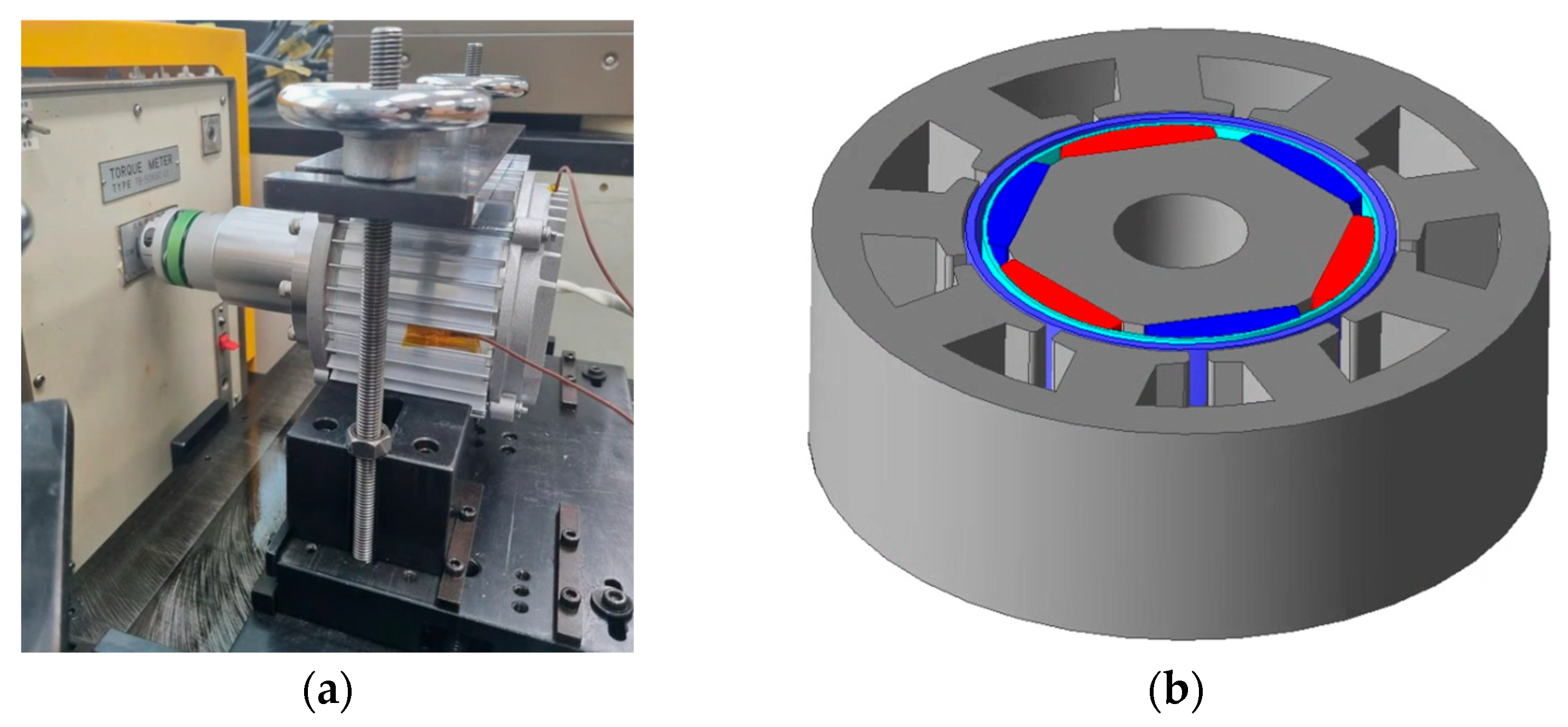
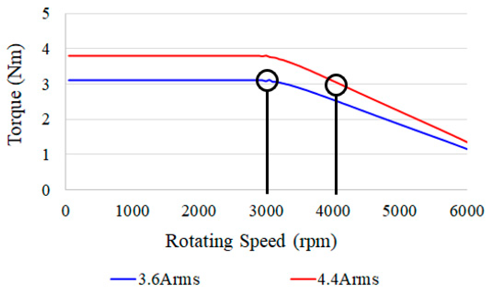
Figure 1 shows both the fabricated model and the simulation geometry of the original motor. Red and blue are magnets, sky blue is a sleeve, and purple is a fluid-proof can. The baseline motor is a 6-pole, 9-slot Radial Flux Motor (RFM) of the Surface Permanent Magnet Synchronous Motor (SPMSM) type. To prevent magnet scattering, a sleeve is applied, and a can is placed in the air gap to block fluid flow. Figure 2 presents the torque-speed (T–N) curve of the original model, where the operating points at rated and maximum output are indicated. The rated operating speed is 3000 rpm, and the maximum speed under full load is 4000 rpm. The key specifications of the original motor are summarized in Table 1. The motor for the pump in Table 1 is a pump motor from Speck of Germany.
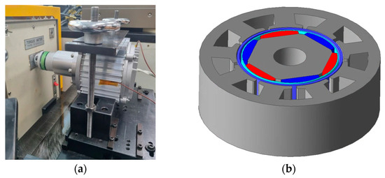
Figure 1.
Radial Flux Motor for pump application: (a) fabricated motor; (b) simulation model geometry.
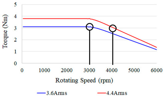
Figure 2.
T–N curve of the original model (rated output: 3.6 Arms, maximum output: 4.4 Arms).

Table 1.
Main specifications of the original model.
In the original model, both a sleeve and a can are applied within the air gap. The sleeve is inserted to prevent magnet scattering, which is a typical consideration in SPMSM designs, while the can serves to block fluid flow. To accommodate both components, the air gap of the original motor is relatively large at 4 mm. Additionally, the motor features a compact, flat structure with a stack length of 40 mm and an outer diameter of 120 mm. The key performance characteristics of the original model are summarized in Table 2.

Table 2.
Key performance characteristics of the original model.
As shown in Table 2, the key performance metrics of the original model are presented. The rated output power is 950 W at a rated speed of 3000 rpm. Under rated operating conditions, the motor produces a torque of 3 Nm, and its efficiency is measured at 92.81%.
3. Conversion of the Original Radial Flux Motor to an Axial Flux Motor Design
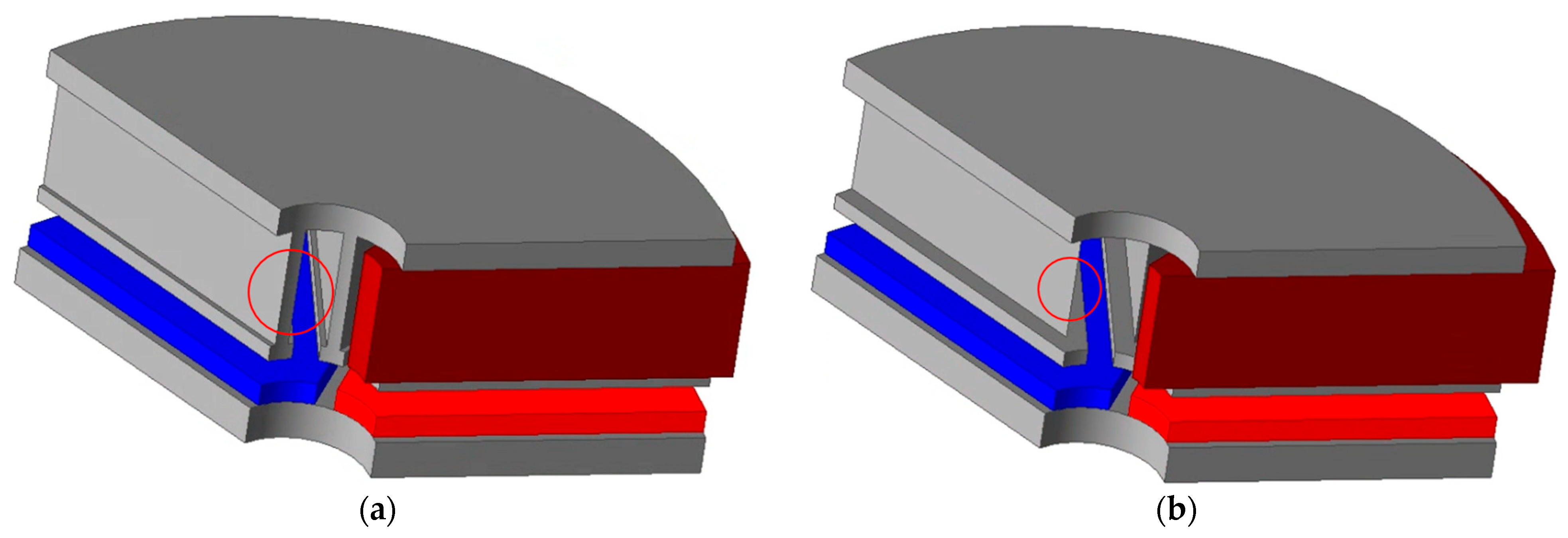
When redesigning the original Radial Flux Motor (RFM) as an Axial Flux Motor (AFM), the initial approach is to maintain the same overall size. Specifically, the same outer diameter and stack length are preserved, and the rotor inner diameter from the original motor is applied as the stator inner diameter in the AFM. In the RFM-to-AFM conversion process, the design of the inner diameter plays a critical role. One key reason for the importance of inner diameter design lies in the low-pole, low-slot configuration. If both the pole and slot counts are low and the inner diameter is small, it becomes difficult to maintain a sufficient thickness in the teeth region of the slot geometry. Assuming a minimum manufacturable teeth thickness of 2 mm, a smaller inner diameter would result in a reduced slot area, limiting the number of coil turns. Conversely, increasing the slot width to accommodate more windings would compromise the teeth thickness, posing challenges in manufacturing. An illustrative example of this design issue is shown in Figure 3.
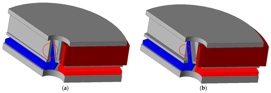
Figure 3.
Stator teeth geometry depending on slot thickness: (a) stator teeth thickness fixed at 2 mm; (b) teeth shape when slot thickness is increased.
Figure 3a illustrates the AFM design in which the inner diameter of the original model is maintained and the stator teeth thickness is set to 2 mm. Under this condition, the slot width becomes extremely narrow, allowing only up to 13 coil turns. On the other hand, if the teeth thickness is reduced to secure a wider slot, the resulting teeth geometry becomes excessively pointed, as shown in Figure 3b, leading to structural instability and manufacturing challenges. Therefore, it is advisable to maintain a minimum teeth thickness of at least 2 mm. While the original RFM model accommodated up to 88 coil turns, the current AFM configuration allows for only 13 turns due to inner diameter constraints, which is expected to significantly impact back-electromotive force (back-EMF) performance. Accordingly, the back-EMF characteristics of the redesigned AFM model, as shown in Figure 3a, were analyzed and compared with those of the original RFM. Figure 4 presents both the back-EMF comparison results and the magnetic saturation distribution of the AFM. As seen in Figure 4a, the back-EMF of the AFM at 4000 rpm is significantly lower than that of the RFM, primarily due to the limited number of coil turns resulting from the narrow slot width. This finding highlights the need to reconsider the inner diameter design. Figure 4b shows the magnetic flux density distribution of the AFM, where severe magnetic saturation is observed in the rotor back yoke. This saturation is attributed to the increased flux passing through the back yoke caused by the low pole count. These results indicate that further optimization of the yoke thickness and magnet geometry is necessary, even under the same stack length. Effectively reducing magnetic saturation can lower core losses and ultimately improve overall motor efficiency.

Figure 4.
Back-EMF and magnetic saturation of the Axial Flux Motor: (a) comparison of back-EMF between the original model and the AFM; (b) magnetic flux saturation in the Axial Flux Motor.
In the design of the inner diameter of an Axial Flux Motor (AFM), it is essential to consider the slot thickness simultaneously. As the inner diameter increases, the design flexibility for slot thickness also improves, making it necessary to adopt a co-optimization approach rather than treating the two parameters independently. Figure 5 illustrates shape variations corresponding to different inner diameters and slot thicknesses. In Figure 5a, structures with inner diameters of 30 mm and 70 mm are compared. It is observed that as the inner diameter increases, the thickness of the teeth in the inner region also increases. This allows for a reduction in teeth thickness and an increase in slot width, thereby enlarging the slot area. As a result, more coil turns can be accommodated, leading to potential improvements in performance. This trend is further illustrated in Figure 5b, which compares slot thicknesses of 5 mm and 10 mm. Notably, when the teeth thickness is reduced to 2 mm, the slot area increases significantly. However, increasing the inner diameter reduces the available outer area for magnets, which in turn lowers the overall magnetic flux density. This leads to a decrease in the magnetic loading ratio and can negatively affect motor performance. Additionally, while a larger slot area enables more coil windings and potentially increases output, it also results in higher copper losses, thereby reducing overall efficiency. Therefore, a careful trade-off is required between output and efficiency, making the co-optimization of inner diameter and slot thickness a crucial design task. Figure 6 presents graphs illustrating the back-EMF and copper loss behavior with respect to different slot thicknesses and motor inner diameters.

Figure 5.
FM geometry according to inner diameter and teeth thickness: (a) geometry variation with different inner diameters; (b) geometry variation with different teeth thicknesses.

Figure 6.
Performance analysis according to slot thickness and motor inner diameter: (a) no-load back-EMF analysis; (b) copper loss analysis.
As shown in Figure 6a, both the slot thickness and the motor inner diameter positively influence the no-load back-electromotive force (back-EMF); increasing either parameter results in higher back-EMF. This analysis was conducted within the constraint of maintaining a minimum teeth thickness of 2 mm. A larger inner diameter allows for a wider slot, accommodating more coil turns and consequently improving motor performance. However, Figure 6b shows that copper losses increase with greater slot thickness and inner diameter. This aligns with previous observations indicating that increasing the number of coil turns to enhance torque also leads to higher copper losses, which in turn reduces efficiency. Interestingly, under a fixed slot thickness, increasing the inner diameter leads to a reduction in copper loss. This is because the effective coil length shortens as the inner diameter increases—the winding radius becomes smaller, resulting in shorter wire per turn and thus lower resistance and copper loss. Of course, a trade-off exists: increasing the inner diameter under constant slot thickness also reduces the area available for magnets, leading to lower back-EMF and potentially diminished output performance. Considering these conflicting effects, a trade-off-based optimization was performed in this study to achieve a balance between motor performance and efficiency. Following the stator design, the next step involves the rotor design. In low-pole-count AFMs, significant magnetic saturation tends to occur in the rotor back yoke. While this saturation does not directly increase core losses, it can contribute to torque ripple and acoustic noise, making it important to manage appropriately. In this study, since additional ripple reduction design steps were planned, the magnetic saturation in the rotor back yoke was allowed within a range that would not excessively increase core loss, providing more design freedom. Figure 7 presents the analysis results for torque and core loss according to changes in rotor back yoke thickness. Figure 7a shows the torque characteristics, while Figure 7b illustrates the corresponding core losses. The analysis was conducted under fixed stack length conditions, with only the rotor teeth length adjusted as the back yoke thickness varied. The results indicate that increasing the back yoke thickness reduces the available space for windings by shortening the teeth, which in turn decreases torque slightly. However, core loss decreases as the magnetic saturation in the back yoke is mitigated. Based on these findings, this study selected a rotor back yoke thickness of 7 mm as the optimal balance between torque performance and core loss minimization. The back yoke thickness was set to 7 mm or less. If it becomes larger than this, it will be difficult to satisfy performance.

Figure 7.
Performance analysis with respect to rotor back yoke thickness and motor inner diameter: (a) torque characteristics; (b) core loss analysis.
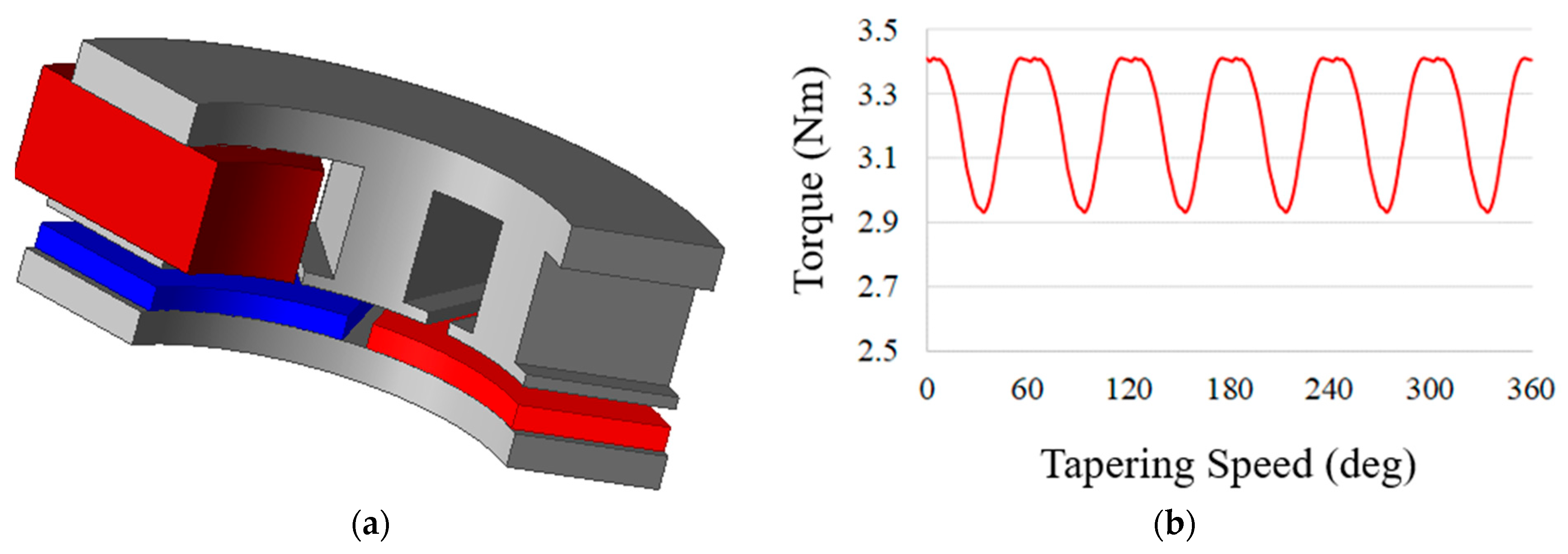
After fixing the rotor back yoke thickness at 7 mm, performance analysis was conducted based on varying slot lengths. The key performance indicators corresponding to different slot lengths are summarized in Table 3. The reason why the slot length starts from 6.5 mm at this time is that if it becomes smaller than 6.5 mm, the slot area becomes too small and it is difficult to satisfy the performance, so the analysis was performed from 6.5 mm. The analysis showed that both core loss and copper loss tend to increase as the slot length increases. This is because longer slots result in thinner stator teeth, which leads to more severe magnetic saturation and thus higher core loss. Furthermore, an increase in slot length allows for more coil turns, which enhances output torque but also increases copper losses. From the efficiency perspective, it was found that the highest efficiency was achieved at a slot length of 6.5 mm. Therefore, a slot length of 6.5 mm was selected for the final design. Based on the preceding analyses, the basic design of the Axial Flux Motor (AFM) was completed, and the model geometry and torque waveform are presented in Figure 8. Figure 8a shows the simulation model of the AFM, while Figure 8b presents the torque waveform over time. The waveform analysis confirmed the presence of relatively large torque ripple. The key performance metrics are summarized in Table 4. According to the results, the cogging torque was measured at 301.5 mNm, which is considerably high. The torque ripple was 0.58 Nm, corresponding to a torque ripple ratio of 18.53%. These values suggest that the current AFM design—configured with a 6-pole, 9-slot combination—exhibits elevated ripple due to electromagnetic factors such as magnetic saturation in the rotor back yoke. Therefore, further design optimization focused on torque ripple reduction is essential.

Table 3.
Analysis of key performance parameters according to slot length.
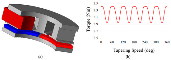
Figure 8.
Axial Flux Motor geometry and torque: (a) simulation model; (b) torque waveform.

Table 4.
Key performance characteristics of the Axial Flux Motor.
4. Torque Ripple Reduction Design
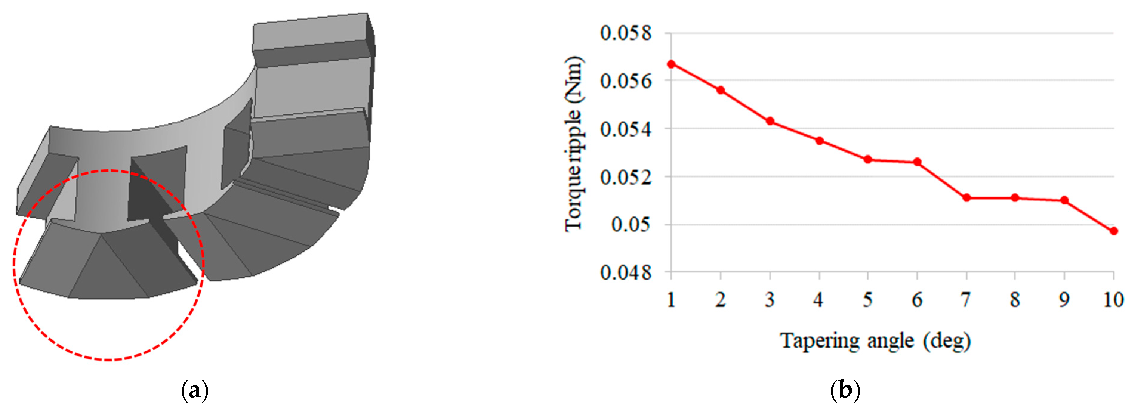
Various techniques have been employed to reduce torque ripple, and in the case of Radial Flux Motors (RFMs), a wide range of methods and extensive research have already been developed. However, for Axial Flux Motors (AFMs), applicable torque ripple mitigation techniques are relatively limited due to structural constraints, and corresponding studies are still insufficient. Among the known methods, applying tapering to the stator shoe region or to the magnets is commonly used for ripple reduction. In this study, two stator-based tapering methods were investigated for AFM ripple mitigation. The first method involves applying symmetric tapering to both sides of the stator teeth, centered at the middle of the teeth width. The tapering geometry and the effect of tapering angle on torque ripple are presented in Figure 9. Figure 9a illustrates the tapering shape applied from the center of the teeth, while Figure 9b shows the variation in torque ripple with respect to different tapering angles. The analysis revealed that as the tapering angle increased, the torque ripple slightly decreased. However, the reduction was marginal, indicating that the overall ripple suppression effect of this method is limited. In this paper, tapering was applied to fabricate a stator using a rolling core, but it was found to reduce manufacturability. For these two reasons, tapering was deemed inappropriate for the stator.
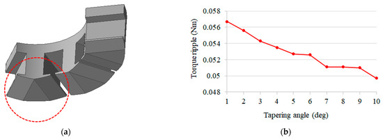
Figure 9.
Tapering applied at the center of the stator teeth: (a) simulation geometry; (b) torque ripple according to tapering angle.
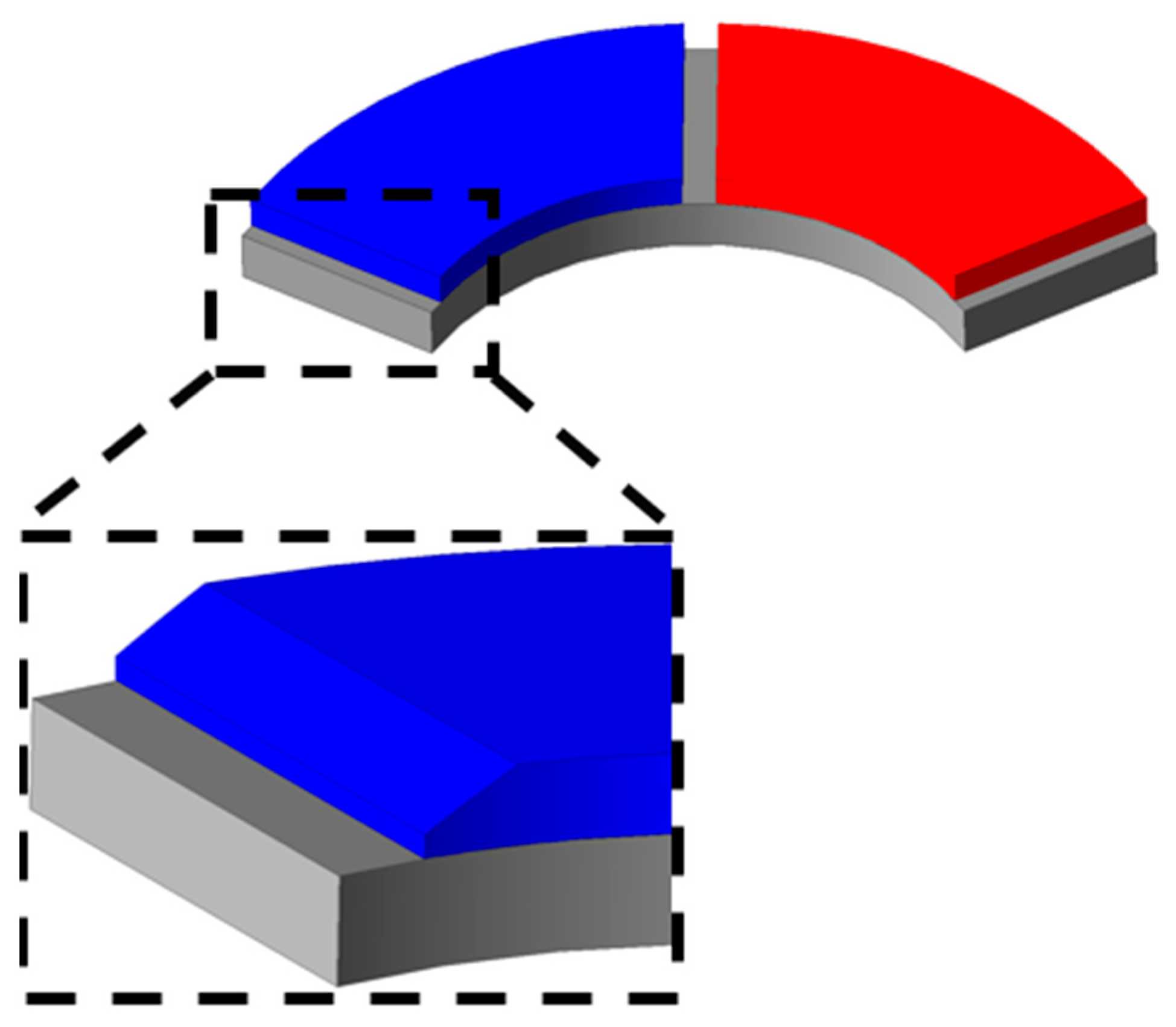
Figure 10 presents the geometry of teeth-centered tapering and its effect on torque ripple across varying tapering angles. The analysis revealed that applying tapering based on the teeth center actually led to an increase in torque ripple, suggesting that this method is ineffective for ripple reduction. In other words, applying tapering to the stator side was found to be insufficient in mitigating torque ripple and was therefore not considered an appropriate design strategy in this study. When tapering is applied to the stator, the shoe becomes thinner. The AFM geometry is sensitive to magnetic saturation, and when tapering is applied to make the shoe thinner, it becomes more vulnerable to magnetic saturation. This increases magnetic saturation in the shoe, which in turn increases the ripple component. Therefore, rather than tapering the stator, a different method must be used. This method involves tapering the magnets. This is because it is believed that this will reduce the amount of magnetic flux coming from the magnets, and by reducing the change in magnetic flux, it will reduce the ripple. As a result, an alternative approach involving tapering on the magnet side was adopted. Figure 11 illustrates the magnet tapering configuration. In applying tapering to the magnets, two primary parameters were considered in this study. The first parameter is the tapering angle, which determines the slant or slope applied to the magnet surface. The second is the tapering length, which defines the starting point along the magnet surface from which the tapering is applied. These two parameters were systematically varied and their impact on electromagnetic performance was analyzed, as shown in Figure 12. Figure 12a shows the average torque values according to changes in tapering angle and length. In this analysis, an average torque of at least 3 Nm was defined as the acceptable performance range. Figure 12b presents the corresponding torque ripple ratio, and design regions where the ripple remained below 5% were selected as optimal. Based on a comprehensive evaluation of these results, the final design values selected in this study were a tapering length of 9 mm and a tapering angle of 16 degrees. Finally, the torque ripple rate is 3.67% and the torque ripple is 0.011 Nm, which is 0.036 for the existing Radial Flux Motor, and the torque ripple of the final model is reduced by 69.4% compared to the existing model. These values enabled the motor to maintain torque performance comparable to the original model while significantly reducing torque ripple. Finally, by applying tapering to the magnet, the torque ripple ratio can be reduced to less than 1%.

Figure 10.
Teeth-based tapering application: (a) simulation geometry; (b) torque ripple according to tapering angle.
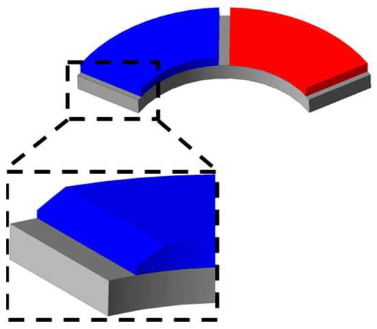
Figure 11.
Geometry of magnet tapering application.

Figure 12.
Analysis of magnet tapering application: (a) average torque according to tapering length and angle; (b) torque ripple ratio according to tapering length and angle.
5. Final Model Analysis
Based on the series of preceding design steps, the original Radial Flux Motor (RFM) was successfully redesigned as an Axial Flux Motor (AFM), incorporating optimal design strategies aimed at improving efficiency throughout the process. One of the key challenges encountered during the conversion was the increase in torque ripple. This issue was thoroughly analyzed, and ripple mitigation was achieved through optimization of both stator and magnet geometries. The key performance indicators of the final AFM design are summarized in Table 5. According to the comparison results in Table 5, the final AFM model maintains a similar level of torque ripple and cogging torque compared to the original RFM, while meeting the same output power conditions. Furthermore, the overall efficiency improved by approximately 1.4 percentage points. These findings demonstrate the effectiveness of the AFM conversion and optimization methods proposed in this study.

Table 5.
Key performance characteristics of the final model.
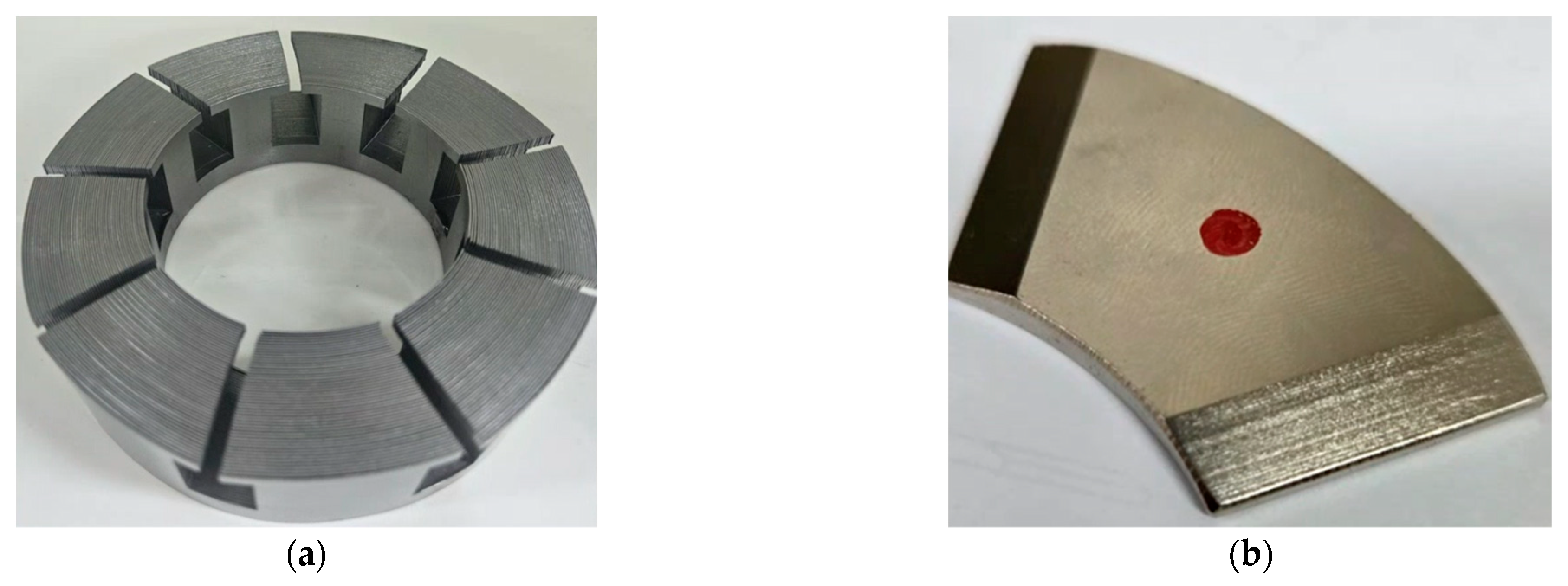
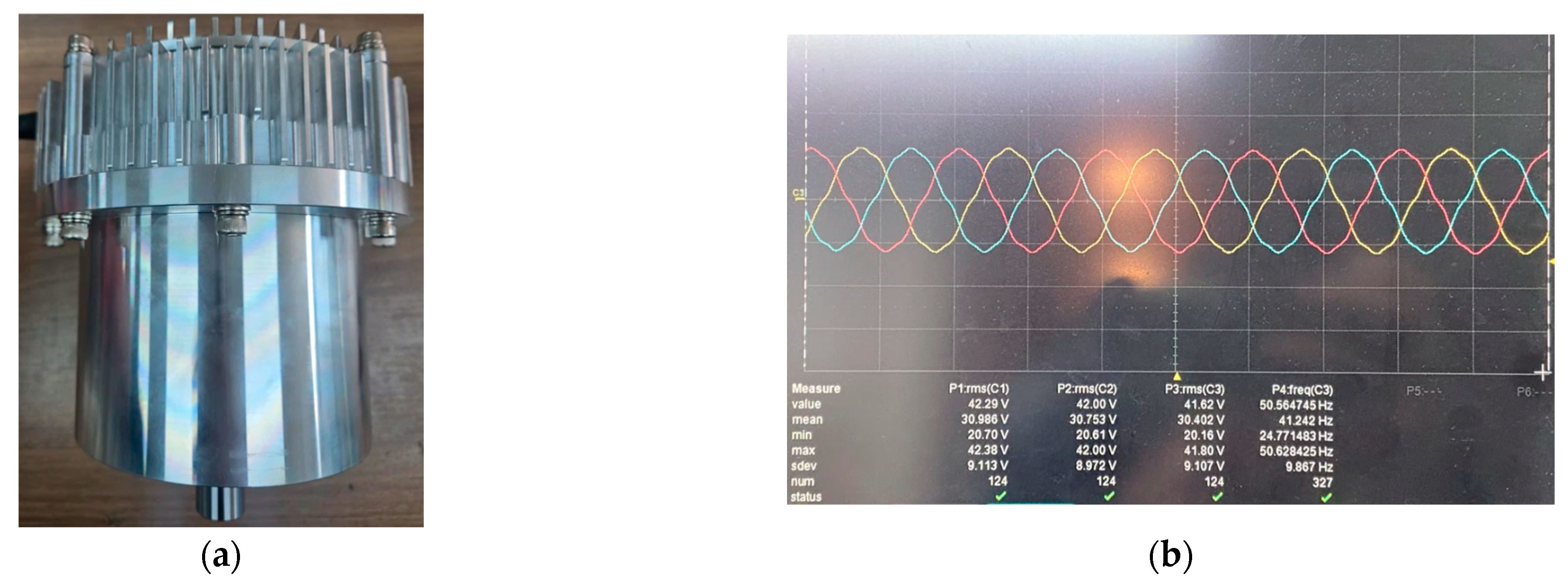
To validate the proposed design, a prototype was fabricated and tested for performance verification. The core was constructed using laminated steel sheets; however, instead of the conventional vertical stacking method used in Radial Flux Motors, a rolling core approach was adopted. In this method, the laminations are wound in a circular form to align with the flux direction in the Axial Flux Motor (AFM). In addition, the magnets were manufactured using the tapering geometry derived from the previous torque ripple reduction design analysis. Photographs of the fabricated core and magnets are presented in Figure 13 and Figure 14 and show the assembled motor and the no-load back-EMF waveform captured using an oscilloscope. Figure 15 shows the test measurements under load. Figure 15a shows the torque according to current, and b shows the output power according to current. The measured results closely matched the simulation data, confirming the validity of the proposed design through experimental verification.
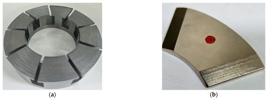
Figure 13.
Fabricated components: (a) rolling core structure; (b) magnet fabricated with applied tapering.
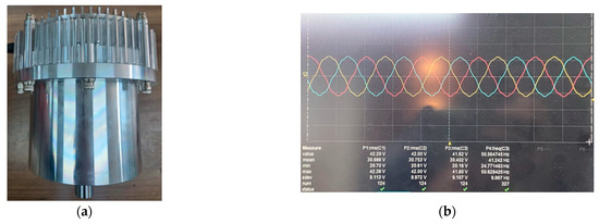
Figure 14.
Fabricated motor and back-EMF measurement: (a) fabricated motor; (b) no-load back-EMF waveform captured by oscilloscope.

Figure 15.
Load test measurements: (a) torque as a function of current; (b) output as a function of current.
6. Conclusions
In this study, a conventional 6-pole, 9-slot Radial Flux Motor (RFM) was successfully redesigned into an Axial Flux Motor (AFM) within the same external volume. To ensure high efficiency and performance even under a low pole-count configuration, an optimized design process and torque ripple reduction strategy were proposed. In the early design phase, the effects of inner diameter and slot dimensions on torque performance, copper loss, and core loss were analyzed, confirming the necessity of co-optimizing the inner diameter and slot thickness. To address the significant torque ripple typically associated with low-pole AFMs, tapering was applied to both the stator and the magnets. The stator tapering method showed limited effectiveness in ripple mitigation. In contrast, a parametric analysis of magnet tapering demonstrated a clear trade-off between ripple reduction and torque output depending on the tapering angle and application length. The optimal tapering parameters were determined to be a 9 mm tapering length and a 16° tapering angle. Unlike traditional AFM manufacturing approaches, which typically rely on soft magnetic composites (SMCs) or solid cores, this study adopted a rolling core technique using laminated steel sheets wound in alignment with the AFM’s flux path. This method ensured both strong electromagnetic performance and manufacturability. A prototype was fabricated and tested under the same output conditions as the original RFM. The results showed that the redesigned AFM maintained similar levels of torque ripple and cogging torque, while achieving an efficiency improvement of approximately 1.4 percentage points. This study addresses practical design challenges in low-pole AFM development and presents concrete strategies to overcome them, including stator and magnet geometry optimization and the application of rolling cores. Future work will focus on implementing additional practical considerations such as thermal management and control optimization to further enhance system-level performance.
Author Contributions
Conceptualization, S.-W.S. and W.-H.K.; Methodology, S.-W.S. and W.-H.K.; Software, S.-W.S.; Validation, S.-W.S. and W.-H.K.; Formal analysis, S.-W.S.; Investigation, S.-W.S.; Resources, S.-W.S.; Data curation, S.-W.S.; Writing—original draft, S.-W.S.; Writing—review & editing, S.-W.S.; Visualization, W.-H.K.; Supervision, W.-H.K.; Project administration, W.-H.K. All authors have read and agreed to the published version of the manuscript.
Funding
This work was supported by the Korea Institute of Energy Technology Evaluation and Planning (KETEP) grant funded by the Korea government (MOTIE) (RS-2024-00419152, Development of 5kW industrial logistics electric platform technology) In part, This work was supported by the Technology development Program (RS-2024-00470254) funded by the Ministry of SMEs and Startups (MSS, Korea).
Data Availability Statement
The original contributions presented in this study are included in the article. Further inquiries can be directed to the corresponding author.
Conflicts of Interest
The authors declare no conflict of interest.
References
- Yi, Y.; Ma, S.; Zhang, B.; Feng, W. Application of High Efficiency and High Precision Network Algorithm in Thermal Capacity Design of Modular Permanent Magnet Fault-Tolerant Motor. Energies 2025, 18, 3967. [Google Scholar] [CrossRef]
- Mlinarič, J.; Pregelj, B.; Dolanc, G. End-of-Line Quality Control Based on Mel-Frequency Spectrogram Analysis and Deep Learning. Machines 2025, 13, 626. [Google Scholar] [CrossRef]
- Choi, D.-H.; Han, H.-S.; Hong, M.-K.; Jung, D.-H.; Kim, W.-H. Design for Loss Reduction in a Compact AFPM Electric Water Pump with a PCB Motor. Energies 2025, 18, 2538. [Google Scholar] [CrossRef]
- Aydin, M.; Gulec, M. A New Coreless Axial Flux Interior Permanent Magnet Synchronous Motor with Sinusoidal Rotor Segments. IEEE Trans. Magn. 2016, 52, 8105204. [Google Scholar] [CrossRef]
- Hong, M.-K.; Pyo, H.-J.; Song, S.-W.; Jung, D.-H.; Kim, W.-H. A Study on the Improvement of Power Density of Axial Flux Motors for Collaborative Robot Joints through Same-Direction Skew. Machines 2023, 11, 591. [Google Scholar] [CrossRef]
- Tak, B.-O.; Ro, J. Analysis and Design of an Axial Flux Permanent Magnet Motor for in-Wheel System Using a Novel Analytical Method Combined with a Numerical Method. IEEE Access 2020, 8, 203994–204011. [Google Scholar] [CrossRef]
- Zhao, H.; Chau, K.T.; Yang, T.; Song, Z.; Liu, C. A Novel Quasi-3D Analytical Model for Axial Flux Motors Considering Magnetic Saturation. IEEE Trans. Energy Convers. 2022, 37, 1358–1368. [Google Scholar] [CrossRef]
- Goh, J.W.; Xie, S.; Wang, H.; Zhu, S.; Yu, K.; Lee, C.H.T. Development of a Surface-Inset Permanent Magnet Motor for Enhanced Torque Density in Electric Mountain Bikes. Energies 2025, 18, 3709. [Google Scholar] [CrossRef]
- Park, Y.-w.; Ko, J.-s.; Kim, D.-k. Optimal Design of Step-Sloping Notches for Cogging Torque Minimization of Single-Phase BLDC Motors. Energies 2021, 14, 7104. [Google Scholar] [CrossRef]
- Abdelwanis, M.I.; Hegab, A.; Albatati, F.; El-Sehiemy, R.A. Adaptive Speed Tuning of Permanent Magnet Synchronous Motors Using Intelligent Fuzzy Based Controllers for Pumping Applications. Processes 2025, 13, 1393. [Google Scholar] [CrossRef]
Disclaimer/Publisher’s Note: The statements, opinions and data contained in all publications are solely those of the individual author(s) and contributor(s) and not of MDPI and/or the editor(s). MDPI and/or the editor(s) disclaim responsibility for any injury to people or property resulting from any ideas, methods, instructions or products referred to in the content. |
© 2025 by the authors. Licensee MDPI, Basel, Switzerland. This article is an open access article distributed under the terms and conditions of the Creative Commons Attribution (CC BY) license (https://creativecommons.org/licenses/by/4.0/).

