Article

Development of Nonlinear Six-Degree-of-Freedom Dynamic Modelling and High-Fidelity Flight Simulation of an Autonomous Airship

1
Department of Aeronautics and Astronautics, Institute of Space Technology, Islamabad 45900, Pakistan
2
Department of Electrical Engineering, University of Engineering and Technology Taxila, Taxila 47080, Pakistan
*
Author to whom correspondence should be addressed.
Processes 2025, 13(9), 2688; https://doi.org/10.3390/pr13092688
Submission received: 11 July 2025 / Revised: 8 August 2025 / Accepted: 22 August 2025 / Published: 24 August 2025

Abstract

An airship is a lighter-than-air vehicle that offers static lift without consuming much power. This property makes it a potential candidate for many commercial applications. The target applications include rescue operations, surveillance, communication, a data collection platform for research activities and payload delivery that requires hovering capabilities, etc. To successfully apply airships in these applications and many others, airship autonomous control development is of paramount importance. To accomplish this goal, the initial step is to model airship dynamics that cover the complete flight envelope accurately. The goal is to develop a flight simulator that can test the advanced autonomous control algorithms. In the proposed work, first, the nonlinear six-degree-of-freedom equations of motion are developed using Newtonian mechanics. These equations are used to develop a flight simulator for the University of Engineering and Technology Taxila (UETT) airship. Airship responses to different control inputs are investigated, and the results are validated with the available data in the literature for other airship projects. Also, the obtained longitudinal and lateral eigenmodes show good agreement with the experimental flight data of the UETT airship. The extensive simulation results favour the dynamic analysis of the airship.

1. Introduction

At the beginning of the twentieth century, airships were considered powerful air vehicles and used extensively in the First World War. Unfortunately, the Hindenburg disaster in 1937 put the brakes on all enthusiasm towards the development of airships. Recent advances in helium production, solar and allied technologies, and research in materials and state-of-the-art technology have produced lightweight, more durable fabrics and materials, which have kindled a renewed interest in airship development for its extensive use in different applications [1,2]. For example, in remote areas with low population density and difficult access, an airship can be a potential solution for local communication services [3].
Due to the vast application areas, a large community around the world has shown interest in airship development and its autonomous control [4]. A key aspect in the successful operation of these systems lies in accurately modelling the dynamics of the airship. Airship modelling has remained a topic of interest for researchers due to its unique buoyant characteristics. Airship modelling has been conducted for different levels of complexity depending on the requirements of usage. The broad categories are summarised in Figure 1.

1.1. Airship Model Estimation

Estimation techniques have played a vital role in finding specific model parameters of interest. An airship dynamic model consists of dynamic, propulsion, gravity, buoyancy and aerodynamic forces. Apart from other things, the modelling of aerodynamic forces remained a challenging task. In the literature, Gomes performed wind tunnel experimentation for determining drag, lift, and side force, as well as rolling, pitching, and yawing motion coefficients. The scaled-down model of YEZ-2A was used in the wind tunnel due to the size limitation of the experimental workspace. Due to the experimentation cost and the sizing constraints, the wind tunnel method puts an economic feasibility constraint on small robotic airship projects, where cost is the vital constraint [5]. Kalman filter-based estimation methods are also proposed for the determination of aerodynamic parameters, as in [6], where the author used both extended and unscented Kalman filters for the determination of aerodynamic model parameters. They determined over 40 parameters, which made the estimation problem computationally complex. To reduce the estimation complexity, in [7,8], the authors worked on the online estimation of aerodynamic forces and torques using both extended and unscented Kalman filters. In [9,10], the authors suggested online estimation of the lumped aerodynamic model, model uncertainties, and wind disturbances. The authors augmented the system with additional auxiliary variables and introduced the disturbance model for augmented variables. However, these online estimations of models can only facilitate the nonlinear controllers. They do not aid in the development of airship models for setting up the simulation environments for controller testing. In [11], the authors tested the online model estimation approach in a closed-loop control environment. The parameter estimation methods that exist for airship modelling provide limited aspects of the model, and they aid the nonlinear controllers in a specific performance range.

1.2. Airship Model Identification

Model identification of aerospace systems using flight data is one of the well-known modelling techniques. In this method, input and output data are used to identify the longitudinal dynamic model or lateral dynamic model of an aerial platform. In [12,13,14], the authors identified aerodynamic model parameters of fighter aircraft. In [15], the authors worked on the model identification of an airship using experimental flight data using the trust region reflective least squares algorithm. The authors identified the longitudinal and lateral state space models for a particular airship flight condition. In [16], the authors used neural network-based intelligent methods for the model identification of an airship using flight data. The system identification method results in a model valid for a particular flight condition, and can be used only for controller design.

1.3. Nonlinear Control-Oriented Modelling

Apart from physical modelling, control-oriented representations of airship dynamics are critical for its guidance, navigation, and control. In [17], the authors formulated the airship’s nonlinear equation of motion for designing a sliding mode controller for its trajectory tracking. In [18], the authors designed an adaptive control strategy for an underactuated system with slow response. The limited aspects of the nonlinear model were considered, as the adaptive controller was expected to adapt to the changes robustly. Moreover, in a control-oriented model, environmental effects are not considered. The nonlinear controller heavily relies on accurate model information; therefore, it sparks the need for a high-fidelity model valid for the entire operating range.

1.4. High-Fidelity Modelling for Simulation

High-fidelity flight simulation models integrate detailed models of airship dynamics with realistic environmental conditions, sensor models, and actuator dynamics. These simulator designs are the first step towards the controller’s extensive testing, system validation, and pilot training. In [5], the author developed a simulation model for the YEZ-2A airship, and the aerodynamic model was based on wind tunnel experimentation. In [19], the authors conducted a comprehensive review of airship design and modelling. All modelling approaches are discussed in detail, plus the ongoing airship projects and future trends. In [20], the authors provided the dynamic modelling of an airship using the MATLAB environment. The aerodynamic model was based on the geometrical parameters of the airship. The results of open-loop experiments are validated with the available data of the YEZ-2A airship. However, the environmental effects and the actuator dynamics are not integrated into the model to make it high-fidelity.
This paper focuses on the development of the airship modelling and simulation environment at the University of Engineering and Technology Taxila (UETT) for the robotic airship. Airship modelling equations are reproduced here using Newtonian mechanics. For aerodynamic models, geometrical parameters of the envelope based on the dynamic equations are used. A nonlinear flight simulator is developed in MATLAB/Simulink. Environmental effects and actuator dynamics are incorporated into the model. The response of the open-loop model is tested under different simulation scenarios where rudder, elevator, and thruster inputs are applied under different time intervals under neutral buoyancy conditions. Moreover, airship longitudinal and lateral models are identified. The eigenvalues of both models are obtained, and different modes of airship motion are analysed. The obtained modes are compared with the available data of different airships and also with the experimental data of the UETT airship. Detailed analysis and conclusions are discussed. The simulation results agree with the dynamics of the airship.
The primary contribution of this research is the development of a high-fidelity, nonlinear six-degree-of-freedom (6-DOF) airship dynamic model, incorporating realistic aerodynamic, aerostatic, and propulsion forces. Unlike previous studies that either employ linearised equations of motion or neglect specific aerodynamic effects, this work presents a comprehensive nonlinear modelling approach using Newtonian mechanics. Additionally, a MATLAB/Simulink-based flight simulator is developed, allowing for real-time dynamic analysis under various control inputs. The model is validated against experimental flight data and benchmarked with existing airship studies, demonstrating improved accuracy in predicting airship responses. The proposed framework serves as a robust platform for testing autonomous control algorithms, bridging the gap between theoretical modelling and real-world implementation.
This paper is divided into a few sections. After the introduction, the airship’s detailed modelling is given in Section 2. The airship flight simulator block diagram is also given. Airship longitudinal and lateral models are obtained in Section 3. The detailed simulation results and discussion are covered in Section 4. The concluding remarks are given in Section 5.

2. Airship Modelling

A dynamic model of the physical system plays an important role in understanding the cause-and-effect relationship of underlying physical phenomena in system operation. The well-developed modelling techniques for air vehicles include theoretical and experimental techniques. Because marine craft and airships are both buoyancy-driven vehicles, in this work, equations of motion (EoM) for an airship are derived following the procedure outlined in [21] for marine craft. Applying the same procedure and method for analysing the motion of a rigid body concerning the inertial frame as outlined in [5], EoM for an airship can be derived. This can be summed up in six coupled nonlinear equations, which are given in the vector form as
M   V ˙ b = F d + F A d h + F A s + F P + F A d c + F w
F d = 6 × 1 Dynamic force vector. It contains Coriolis forces and centrifugal forces.
F A d h = 6 × 1 Aerodynamic force vector. It comprises forces acting on the airship hull due to air, when it cruises through it.
F A s = 6 × 1 Aerostatic force vector. It contains forces due to buoyancy and airship weight.
F P = 6 × 1 Propulsion force vector. It contains forces acting on the airship due to thrusters.
F A d c = 6 × 1 Aerodynamic forces acting on the airship due to control surface deflection.
F w = 6 × 1 Wind gust acting on the airship.
M = 6 × 6 Mass matrix. It contains airship mass, added mass, inertia, and added inertia terms.
V b = 6 × 1 Vector u ˙ v ˙ w ˙ p ˙ q ˙ r ˙ T containing linear and angular acceleration terms in the airship body reference frame.

2.1. Dynamic Forces

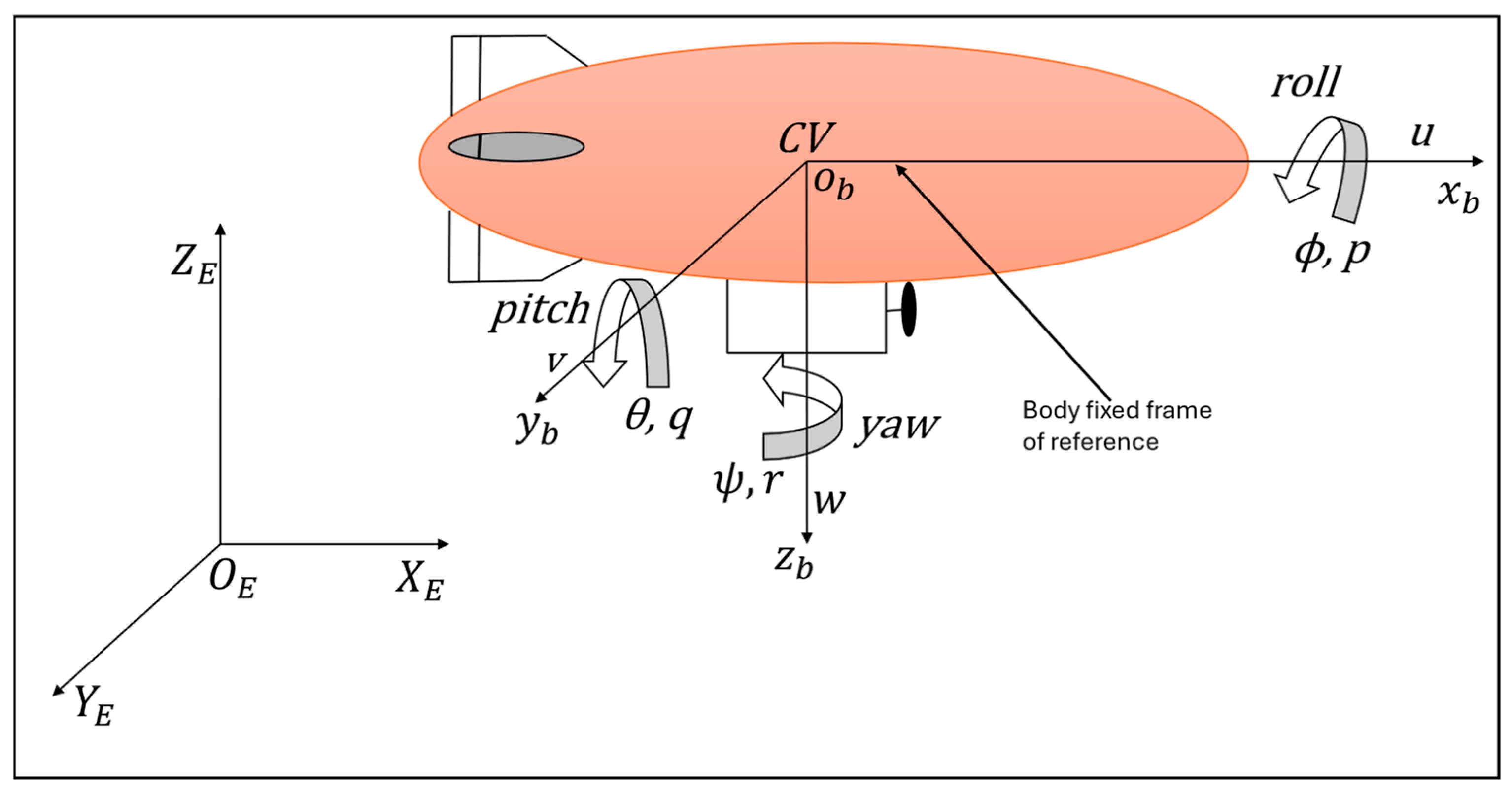
The motion of an airship is described by two reference frames: a body-fixed frame ( O b X b Y b Z b , where the subscript b denotes the body and O b denotes the centre of volume of the airship) and an inertial frame ( O E X E Y E Z E , where the subscript denotes the Earth and denotes the centre of the reference frame; in this case, it will be some point on Earth), as shown in Figure 2. It is assumed that the centre of volume (CV) of the blimp coincides with the centre of the body-fixed frame. The body-fixed frame can rotate as well as translate concerning the inertial frame. The inertial frame is attached to the Earth and does not move. Airship position and attitude are expressed with respect to the inertial frame and are represented by Χ = x , y , z and Θ = ϕ , θ , ψ , respectively. Airship linear and angular velocities aligned with local reference frames have a representation of υ = [ u , v , w ] and Ω = p , q , r , respectively. X I is a state vector representing airship position and altitude. V b is a state vector representing airship linear and angular velocity. Equation (1) is rearranged, and the modified equation is given in (2).
V ˙ b = M 1 F d + F x
where F x = 6 × 1 is the external force vector that includes F A d h , F A s , F P , F A d c ,   a n d   F w .
Equation (3) describes the mass matrix.
M = m x 0 0 0 m 15 0 0 m y 0 m 24 0 m 26 0 0 m z 0 m 35 0 0 m 42 0 J x 0 J x z m 51 0 m 53 0 J y 0 0 m 52 0 J x z 0 J z
The mass matrix contains the airship’s actual mass and inertia as well as the added mass and inertia terms. The added terms result from the mass of air displaced by the airship. Equation (4) describes the dynamic force vector. The dynamic force vector summarises the forces and torques acting on the airship due to centrifugal and Coriolis effects.
F d = m z w q + m y r v + m a x q 2 + r 2 a z r p m x u r + m z p w + m a x p q a z r q m y v p + m x q u + m a x r p + a z q 2 + p 2 J z J y r q + J x z p q + m a z u r p w J x J z p r + J x z r 2 p 2 + m a x v p q u a z w q r v J y J x q p J x z q r + m a x u r p w
The details of the parameters used in Equations (3) and (4) are
V :Airship volume
m :Mass of airship
g :Gravitational acceleration
H :Airship heaviness value (it is zero for the neutral buoyancy case)
J x :Moment of inertia about x-axis
J y :Moment of inertia about y-axis
J z :Moment of inertia about z-axis
J x z :Moment of inertia about xz-axis
l :Length of airship
d :Airship maximum diameter
B f = ρ g V
W = B + H g
m x = m X u ˙
m y = m Y v ˙
m z = m Z w ˙
m 15 = m a z X q ˙
m 24 = m a z Y p ˙
m 26 = m a x Y r ˙
m 35 = m a x Z q ˙
m 42 = m a z L v ˙
m 51 = m a z M u ˙
m 53 = m a x M w ˙
m 62 = m a x N v ˙
Z w ˙ = Y v ˙
N r ˙ = M q ˙
m ¯ = B / g
I ¯ y = m ¯ ( l 2 + d 2 ) 20

2.2. Aerostatic Forces

Constant restoring forces acting on an airship are called aerostatic forces. There are two types: the buoyancy force and the gravitational force. The buoyancy force acts on the centre of volume, and the gravitational force acts on the centre of gravity (CG), mainly due to the weight of the airship. The direction of the gravitational force is considered positive. Let V be the volume of air displaced by the airship body, g the acceleration due to gravity, and ρ the density of air, and then the weight of the airship and the buoyancy force acting on it will be as follows:
W   =   m g
B f = ρ g V
F A s = W B f s θ W B f c θ s ϕ W B f c θ c ϕ a z W c θ s ϕ ( a z W b z B f ) s θ ( a x W b x B f ) c θ c ϕ a x W c θ s ϕ
where W is the airship weight, B f is the buoyancy force, { a x , a z } are the coordinates of CG of the airship with reference to the CV, and { b x ,   b z } are the coordinates of the centre of buoyancy of the airship with reference to the CV. Moreover, s θ = sin θ , c θ = cos θ , s ϕ = sin ϕ , and c ϕ = cos ϕ .

2.3. Aerodynamic Forces

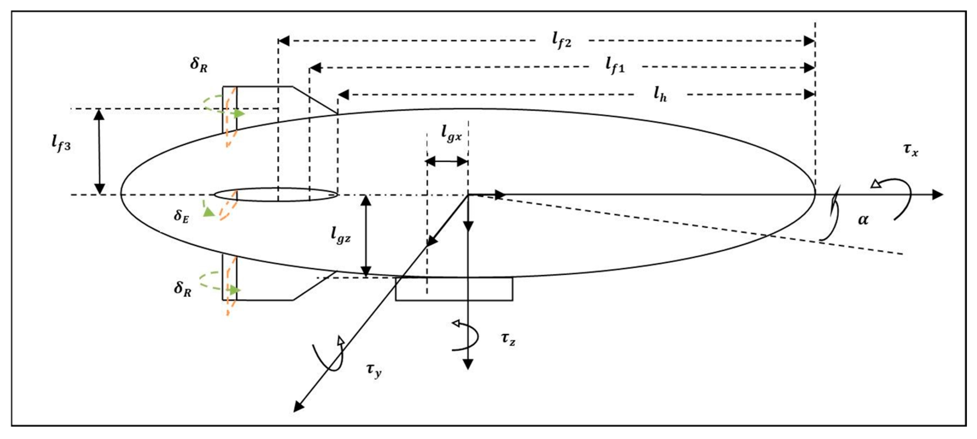
An aerodynamic model that depends on the angle of attack ( α ), sideslip angle ( β ), and the geometric parameters of the airship body has been proposed in [20]. The aerodynamic forces and moments are evaluated from the nose to the start of the fins. The model is a good approximation of the physical behaviour of airship aerodynamics. In this paper, an airship aerodynamic model based on the geometric parameters is adopted, given by Mueller [22]. The drag force, side force, lift force, and moment coefficients are derived using the geometric parameters of the airship. The airship geometrical parameters used in the aerodynamic model are given in Figure 3. These coefficients are given below:
Drag force coefficients [22]:
C X 1   =   [ C D h 0 S h   +   C D f 0 S f   +   C D g 0 S g ]
C X 2 = K 2 K 1 η K I 1 S h
C X 3 = C D c h J 1 S h + C D c f S f
Side force coefficients:
C Y 1 = C X 2
C Y 2 = 1 2 C L α   f S f η f
C Y 3 = [ C D c h J 1 S h + C D c f S f + C D c g S g ]
C Y 4 = 1 2 C L α   f S f η f
Lift force coefficients:
C z 1 = C y 1
C z 2 = C y 2
C z 3 = C D c h J 1 S h + C D c f S f
Rolling torque coefficients:
C L 1 = C L δ f S f η f l f 3
C L 2 = C D c g S g l g z
Pitching torque coefficients:
C M 1 = K 1 K 2 η K I 3 S h L
C M 2 = 1 2 ( C L α ) f S f η f l f 1
C M 3 = C D c h J 2 S h L + C D c f S f l f 2
C M 4 = 1 2 C L δ f S f η f l f 1
Yawing torque coefficients:
C N j = C M j
where
  • C D h 0 : hull zero-incidence drag coefficient;
  • C D f 0 : fin zero-incidence drag coefficient;
  • C D g 0 : gondola zero-incidence drag coefficient;
  • C D c h : hull crossflow drag coefficient;
  • C D c f : fin crossflow drag coefficient;
  • C D c g : gondola crossflow drag coefficient;
  • ( C L α ) f : derivative of fin lift coefficient with respect to the angle of attack at zero incidence;
  • C L δ f : derivative of fin lift coefficient with respect to the flap deflection angle;
  • S h : hull reference area;
  • S f : fin reference area;
  • S g : gondola reference area;
  • l f 1 : x-distance from origin to aerodynamic centre of fins;
  • l f 2 : x-distance from origin to geometric centre of fins;
  • l f 3 : y, z-distance from origin to aerodynamic centre of fins;
  • l g x : x-distance from origin to aerodynamic centre of fins;
  • l g z : z-distance from origin to aerodynamic centre of fins;
  • η f : fin efficiency factors accounting for the effect of the hull on the fins;
  • η k : hull efficiency factor accounting for the effect of the fins on the hull.
I 1 = π b 2 V 2 3 ( 1 f 2 )
I 3 = π b 2 3 L V 2 3 a 1 2 a 2 f 3 3 a 1 f 2 x c v L I 1
J 1 = b 2 V 2 3 a 1 π 2 + a 2 1 f 2 f + 2 a 2 sin 1 f
J 2 = J 1 a 1 x c v L + 2 b 3 L V 2 3 a 2 2 a 1 2 a 2 2 1 f 2 3 2
f = l h a 1 a 2
l h is the length of the hull up to the leading edge of the fins.
The origin of the body frame is located at the airship’s centre of volume. For the double-ellipsoid geometry, the centre of volume is located on the x-axis at the point:
x c v = a 1 + 3 8 a 2 a 1
The aerodynamic forces acting on the airship hull given by [22] can be expressed by the following equation:
F A d   =   F A d h   +   F A d c
F A d = f ( V t ) C X 1 c α 2 c β 2 + C X 2 s 2 α s α 2 C Y 1 c β 2 s 2 β + C Y 2 s 2 β + C Y 3 s β s β + C Y 4 ( δ R T + δ R B ) C z 1 c α 2 s 2 α + C z 2 s 2 α + C z 3 s α s α + C z 4 ( δ E L + δ E R ) C L 2 s β s β + C L 1 δ E L δ E R + δ R B δ R T C M 1 c α 2 s 2 α + C M 2 s 2 α + C M 3 s α s α + C M 4 ( δ E L + δ E R ) C N 1 c β 2 s 2 β + C N 2 s 2 β + C N 3 s β s β + C N 4 ( δ R T + δ R B )
where
f V t = 1 2 ρ V t 2 ,
V t = ( u 2 + v 2 + w 2 )
c α = cos α
c β = cos   β
s 2 α = sin 2 α
s α 2     = sin α 2
s α = sin α
s α = sin | α |
c α 2 = cos α 2  
c β 2 = cos β 2
s 2 β = sin 2 β
s β = sin | β |
s β = sin β
δ R T =Top rudder deflection
δ R B =Bottom rudder deflection
δ E L =Left elevator deflection
δ E R =Right elevator deflection
Remark 1. 
Airship roll angle and pitch angle satisfy the bounds { ϕ < π 2 ; θ < π 2 }, which ensures the non-singularity of the rotation matrix.
Assumption 1. 
Airship CG point lies beneath the CV, and its centre of buoyancy is coincident with the CV. The airship is in a neutral buoyancy state such that its weight and buoyancy are equal. Consequently, the aerostatic forces do not affect horizontal dynamics. The given 6-DOF (6-degree-of-freedom) equations ignore the aeroelastic effects and consider the airship as a rigid body. However, controller design considers these effects as model uncertainties.

2.4. Propulsion Forces

The airship’s piloting is achieved mainly by propellers mounted on the gondola and at the tail of the airship. Two propellers are mounted on the gondola to produce vectored thrust. These propellers can be moved in the longitudinal plane with an angle µ. Both propellers can be tilted at the same angle. To ease the controller design process in the current configuration, it is assumed that both propellers rotate at the same speed. One propeller is mounted at the tail fin, which is mainly used for generating extra yaw control. The 6   × 1 column matrix containing the terms associated with the propulsive forces and moments is given by
F P = 2 T d cos μ T l 2 T d sin μ 0 2 T d ( d z cos μ d x sin μ ) T l d y
where μ is propeller tilt angle; T l is tail propeller thrust; and d x , d y , and d z are the coordinates of the propeller from the CV of the airship. The expression used to estimate thrust generated by each engine is given as follows:
T d   = P a η p V t
where P a is available power and η p is the propeller efficiency.

2.5. Kinematics

For an airship moving in 6-DOF, six independent coordinates are necessary to determine its position and orientation. Its position and orientation are usually determined concerning the fixed axis. In light of the above discussion, it will be an inertial frame of reference. In a simulation, an airship’s linear and angular velocities are measured with respect to the body frame of reference, so it will be required to transform them into inertial frames. A transformation matrix is used for this.
Let linear and angular velocities in the inertial frame be
V I = X , φ T
where
X = [ X ˙ , Y ˙ , Z ˙ ] T   and   φ = ϕ ˙ , θ ˙ , ψ ˙ T
Let linear and angular velocities in the body frame be
V b = [ V , ω ] T
where
V = u , v , w T and   ω = [ p , q , r ] T
Let
ϑ = ϕ , θ , ψ T
Then
V I = R ( ϑ ) V b
where R ( ϑ ) is the Direction Cosine Matrix (DCM)
R ϑ = R 1 ϑ O 3 X 3 O 3 X 3 R 2 ϑ
R 1 ( ϑ ) is defined as
R 1 ϑ = cos ψ cos θ cos ψ sin θ sin ϕ sin ψ cos ϕ cos ψ sin θ cos ϕ + sin ψ sin ϕ sin ψ cos θ sin ψ sin θ sin ϕ + cos ψ cos ϕ sin ψ sin θ cos ϕ cos ψ sin ϕ sin θ cos θ sin ψ cos θ cos ψ
and R 2 ( ϑ ) is defined as
R 2 ϑ = 1 sin ϕ tan θ cos ϕ tan θ 0 cos ϕ sin ϕ 0 sin ϕ sec θ cos ϕ sec θ

2.6. Atmospheric Model

The standard atmospheric model is incorporated as given in Equation (20). The Atmosphere and Incidence Airspeed Computation subsystem approximates the International Standard Atmosphere (ISA) and is split into two regions. The troposphere region lies between sea level and 11 km and has a linear temperature drop that corresponds to changing altitude. The lower stratosphere region ranges between 11 km and 20 km and has a constant temperature.
Troposphere   model = T = T 0 L h ρ = ρ 0 T T 0 g L R 1 P = P 0 T T 0 g L R α t = γ R T
where
T 0 = Absolute temperature at mean sea level [K]
ρ 0 = Air density at mean sea level [kg/m3]
P 0 = Static pressure at mean sea level [N/m2]
h = Altitude (m)
L = Lapse rate [K/m]
R = Gas constant [J/kg/K]
g = Gravitational acceleration [m/s2]
T = Temperature at altitude h
ρ = Air density at altitude h
P = Static pressure at altitude h
a t = Speed of sound at altitude h

3. Analysis of Linearised Longitudinal and Lateral Models of UETT Airship

The complex nonlinear EoM for the airship as given in Section 2 justifies the search for a linear version. It is a usual practice in aeronautical systems to linearise the vehicle dynamics around a trimmed flight condition. This simplifies the analysis and evaluation of vehicle characteristics. For the evaluation and validation of the UETT airship model characteristics, in this section, its nonlinear modelling equations are linearised about a trimmed flight condition. The airship linearised longitudinal and lateral models are obtained. The airship longitudinal and lateral eigenmodes are also identified from a linearised model. These modes are verified with flight data and are compared with the available data for other airships.

3.1. Trim Flight Conditions

The trimming corresponds to the act of finding an equilibrium by adjusting an input. Trim points are sometimes called operating points. A trim point is a combination of system states and inputs that yields a particular desirable behaviour. The trimming term is mainly used for air vehicles. For example, finding a trim point for an air vehicle will correspond to finding a certain combination of elevator and thrust input that yields a level flight having a certain forward velocity and angle of attack, as well as a constant height. The trim point differs from the equilibrium point. An equilibrium point can be called a special type of trim point where all state derivatives must be zero.
The airship nonlinear model in compact form can be written in the equation. Here, the disturbance is not considered.
x ˙ = f ( x ,   U )
where for the airship model the trim point can be defined as the point ( x , u )   =   ( x e ,   u e ) , where the subset of airship states reaches its steady state value, or mathematically y ˙ e   =   0 .
x ˙ e = f x e ,   U e = 0
y ˙ e = c x ˙ e = 0
This implies that there is a balance between forces acting on the airship, and the airship will remain in that particular flight condition until some disturbance or some control input occurs. Prior to the linearisation, the first step is to find the trim point ( x e ,   U e ) for a particular airship speed. Due to the complex airship dynamics, it is not easy to find the trim point analytically. Therefore, a MATLAB 2019a toolbox ‘Model Linearizer’ is used that solves the convex optimisation problem with constraints that meet the straight level flight condition.
  • For a straight level flight, airship should maintain a particular height p z   =   p z e and have constant forward velocity u   =   u e .
  • The derivative for linear and angular velocities are zero: u ˙ ,   v ˙ ,   w ˙ ,   p ˙ ,   q ˙ ,   r ˙ =   0 .
  • The angular velocities and derivative of height are zero: p ,   q ,   r ,   p ˙ z   =   0 .
  • For pure longitudinal flight, the roll angle and angle of attack are zero: α ,   ϕ   =   0 .
  • The derivative of Euler angles is zero: ϕ ˙ ,   θ ˙ ,   ψ ˙ =   0 .
  • For level flight, θ   =   α .
  • For forward motion, rudder deflection will be zero: δ R   =   0 .
  • Airship will have certain thrust input to maintain forward motion, δ t   =   δ t e .
  • Airship will have certain elevator deflection, δ E   =   δ E e .
  • It is not necessary for p x ,   p y to obtain steady-state condition. Straight level flight having any direction is permitted.
Under the above constraints, the MATLAB program will give the following trim point:
x e = [ p z e 0 θ e u e 0 w e 0 0 0 ]
u e = [ δ E e δ t e 0 ]
where ‘ ’ means don’t-care value. This means that whatever value selected for these variables, it will not affect the trim point.
For UETT airship at u e   =   5.5   m s 1 , the following trim point is obtained:
x e = [ 10 10 67 0 0.0068022 0 5.5 0 0.037413 0 0 0 ]
U e = [ 0.0409 19.3 0 ]

3.1.1. Longitudinal Model

The longitudinal dynamics of the airship motion can be modelled with the motion variables and control inputs related to vertical and forward motion. The linear longitudinal sub model can be expressed with the following notation:
x ˙ l o n   =   A l o n x l o n   +   B l o n u l o n
The longitudinal states consist of the following elements:
x l o n = u w q θ T
The longitudinal motion variables are excited by the elevator deflection and throttle inputs:
u l o n = δ E δ t T
Numerical differentiations are performed of UETT airship nonlinear dynamics at the trimmed points given in Equation (26a,b). The following linearised longitudinal model is obtained:
x ˙ l o n = 0.1114 2.1378 0.1326 2.8221 0.0065 1.0803 2.9776 0.5230 0.0114 2.4011 0.2260 3.1762 0 0 1 0 x l o n + 0.7804 0.0085 0.7662 0 0.8783 0.0012 0 0 u l o n
The experimental flight of the UETT airship has been conducted and the collected data has been used to identify the longitudinal and lateral models [15]. The longitudinal model of the UETT airship is given as
x ˙ l o n = 0.2136 0.06769 4.55 0.7457 0.1644 0.5315 11.28 4.786 0.09217 0.04482 0.01986 0.4048 0 0 1 0 x l o n + 0.4163 0.01734 1.055 0 0.05003 0.00696 0 0 u l o n

3.1.2. Lateral Model

The airship lateral sub-model can be described by the motion variables related to the directional motion of the airship. The lateral sub-model can be expressed by the following notation:
x ˙ l a t   =   A l a t x l a t   +   B l a t u l a t
The lateral states consist of the following elements:
x l a t = v p r ϕ T
The lateral motion variables are excited by the rudder deflection:
u l a t = δ R T
Numerical differentiations are performed for the UETT airship nonlinear dynamic model at trimmed points given in Equation (26a,b). The following linearised lateral model is obtained:
x ˙ l a t = 1.9401 0 0.1717 14.6583 2.1202 0 5.8678 29.5327 1.7961 0 0.3312 1.6668 0 1 0.025 0 x l a t + 1.3490 1.5046 0.6227 0 u l a t
The lateral model of the UETT airship from experimental flight data is given by [15]:
x ˙ l a t = 0.2621 1.306 3.171 1.321 0.0746 1.326 2.04 0.7108 0.002476 1.069 0.4324 0.199 0 1 0.025 0 x l a t + 0.8047 0 0.012 0 u l a t

4. Results and Discussion

The purpose of this section is to report the results of investigations made for the UETT airship response subject to various types of control inputs. The first type of control input was the deflection of aerodynamic control surfaces, including the rudder and elevator. The second type of control input was associated with power control, i.e., thrust changes. This section is divided into three subsections where investigations made for elevator, rudder, and thruster commands are reported under different cases. The sensitivity of the response is assessed under variation in control input magnitude. The results are validated by comparing the response with published data of YEZ-2A, AURORA, LOTTE, JPL AEROBOT, and UETT airships in the ‘Validations of Simulation Results’ Section.
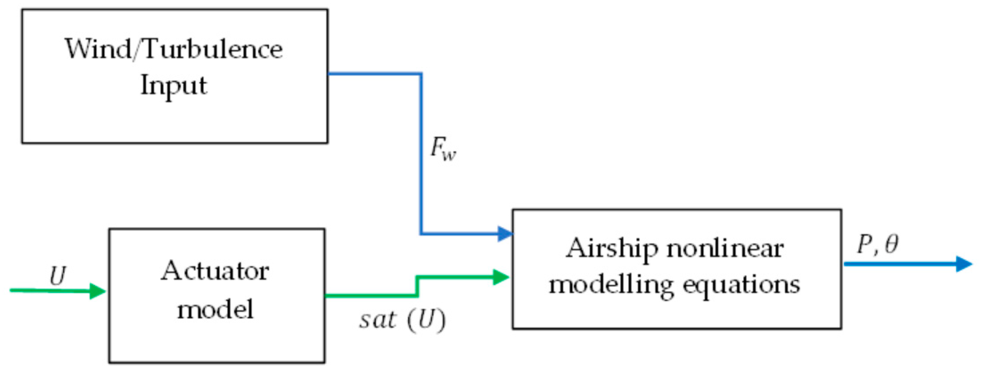
The 6-DOF nonlinear simulation environment for the UETT airship is developed in MATLAB/Simulink. For open-loop simulations, wind forces are not considered, and it is assumed that the airship model parameters are constant. The block diagram of the simulator is shown in Figure 4. Table 1 gives nominal values for the mass matrix parameters. The data in Table 1 were obtained during experimentation using an electronic balance. The mass of the airship and the payload remain constant during the flight. The mass of the airship may change in the case of helium gas leakage, or air balloon inflation or deflation. The air ballonets are kept deflated, and the leakage of the helium gas is not observed during the experimentation. Therefore, for this simulation, the mass variation is not considered. The available data in the literature for the UETT airship considers the neutral buoyancy condition, and the experiments are conducted at an altitude of 67 m. Therefore, in the current simulation setup, it is assumed that the altitude variation of the airship is slight, between 0 m and 67 m. So, the neutral buoyancy condition is considered. Airship added mass and inertia terms are given in Table 2. Airship geometrical parameters are given in Table 3, and the aerodynamic parameters are given in Table 4.
Airship simulator response is evaluated under different test cases, as summarised in Table 5.

4.1. Case 1: Response to Elevator Input

The objective of this part is to evaluate the airship motion variables when elevator input is applied for a short interval of time and then withdrawn. Different amplitudes of elevator deflections are applied and time histories of changes in flight variables are plotted for comparison. Elevator deflection is responsible for exciting the longitudinal flight variables of the airship. The relevant motion parameters are selected as follows:
δ E :Elevator deflection in radians
θ :Pitch angle in radians
q :Pitch rate in radians per second
α :Angle of attack in radians
ω :Vertical velocity in meters per second
p z :Height in meters
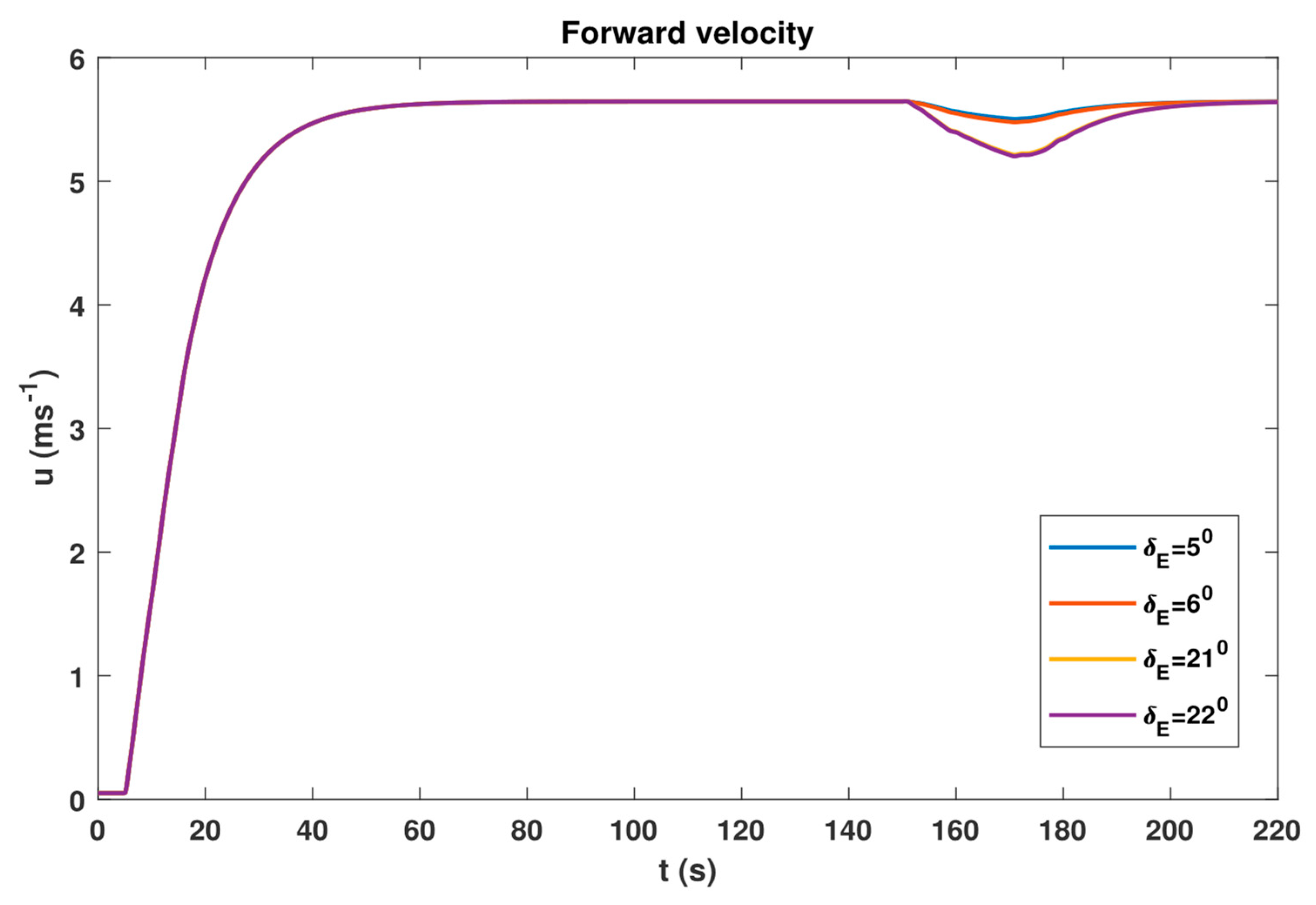
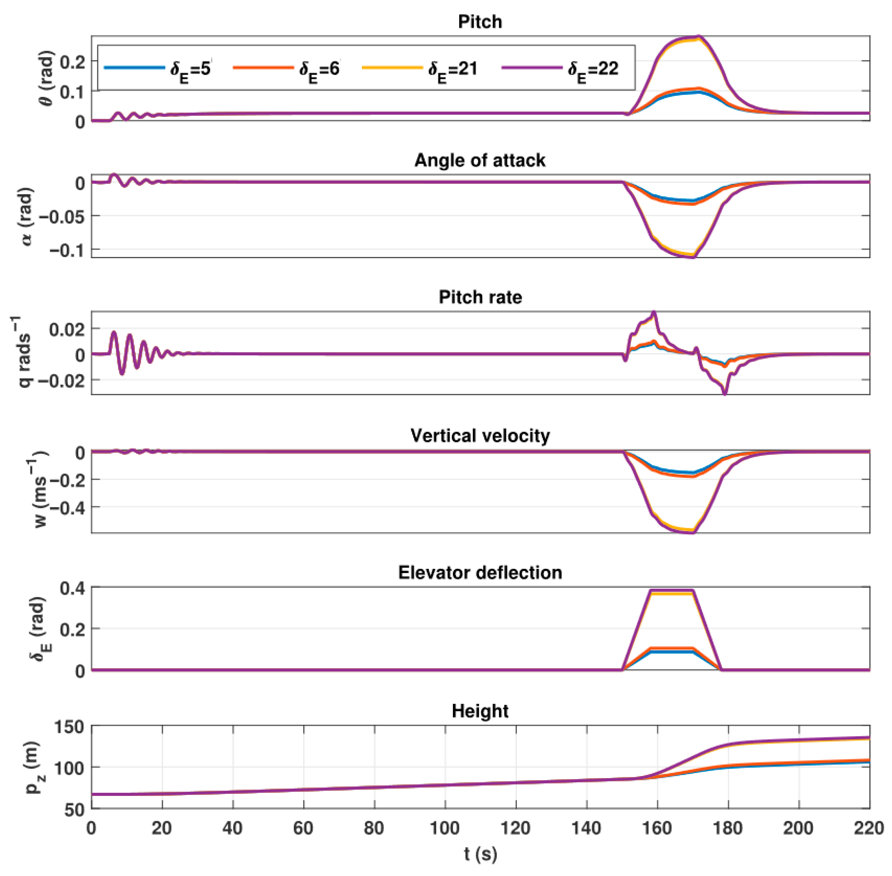
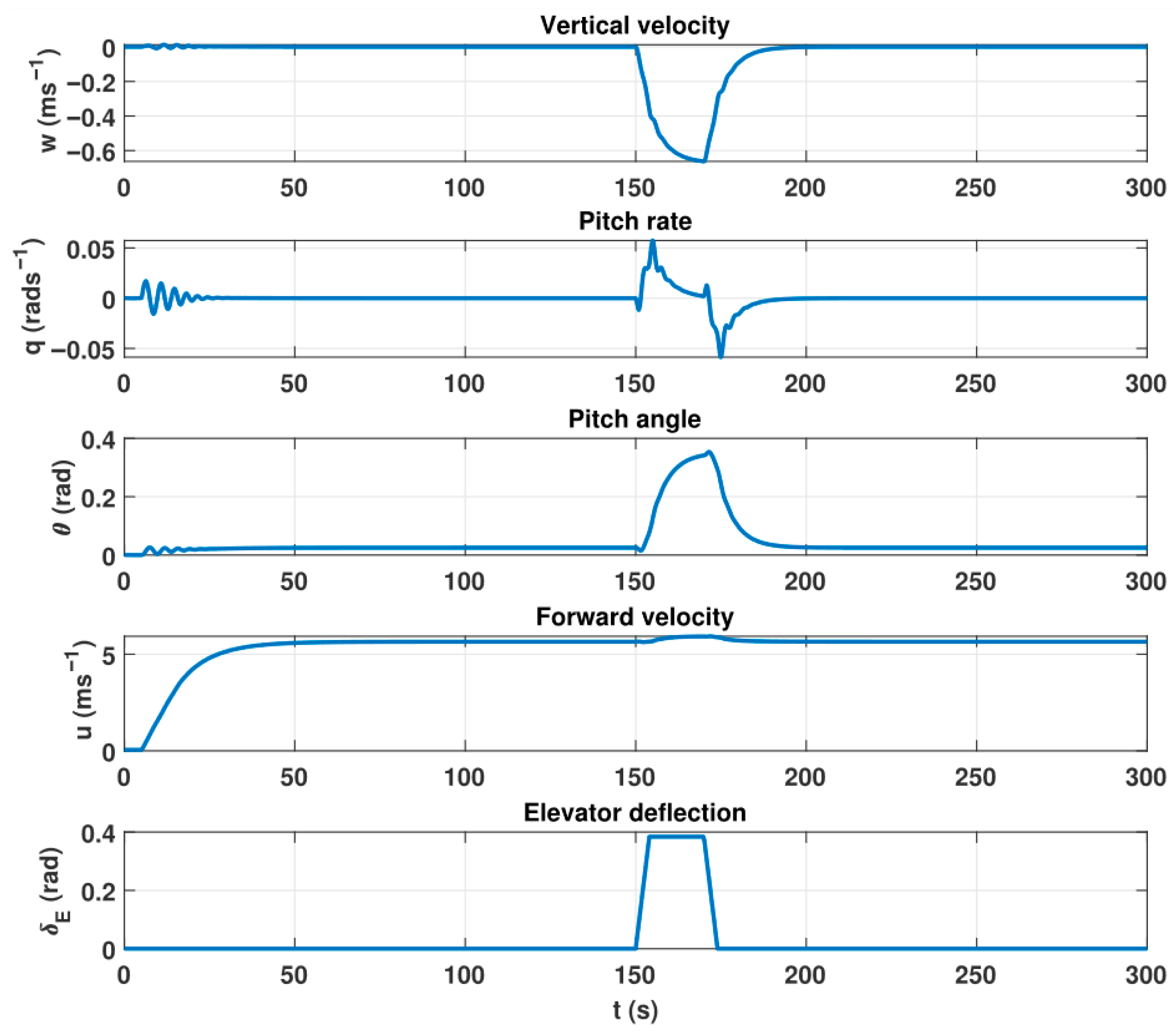
Two types of simulation experiment are conducted to study the response to the elevator input. In the first type, a small magnitude of elevator input is given, and in the second type, investigations are made under a large magnitude. In both instances, the airship speed, mass, inertia, and environmental conditions are kept the same. It is assumed that the airship is hovering at 67 m of altitude. International Standard Atmosphere (ISA), sea level, and neutral buoyancy conditions are assumed. After 5 s of a simulation run, the thruster command is applied with a zero-tilt angle. The airship achieves a steady state after 25 s of the simulation run. The airship stays in a steady state with 5.5 ms−1 of forward velocity for 150 s, as shown in Figure 5. At 150 s, a 5-degree elevator deflection is applied for 15 s. The elevator deflection reduces the forward velocity of the airship. Moreover, the airship starts climbing with a certain vertical velocity. Simulation is executed for 300 s, and the time histories are given in Figure 6.
The physical interpretation of results from the plot of pitch angle suggests that elevator input introduces prominent changes in the airship attitude. As the input is applied, a change in pitch angle can be seen. On the removal of the input, the pitch angle declines to its initial value. In other words, the airship nose went down and achieved its initial value due to the thrust input. The same sort of observation can be made for the airship velocity along the z-axis. Due to the change in velocity, the airship’s altitude changes. An interesting observation can be made for the pitch rate response. It is a non-minimum phase response. Because the control surfaces (both rudder and elevator) are situated on the tail of the airship, far behind the centre of mass of the airship, airship motion variables experience a non-minimum phase response to the elevator. This phenomenon can be reduced if the control surfaces are attached to or near the CG of the airship.
Similar behaviour is also seen in the available measured data for the UETT airship (which will be discussed later in a separate section). When the upward deflection is given to the elevator, the downward force on the tail is instantly generated. This force pushes the airship body down relative to the inertial reference frame; therefore, the centre of mass of the airship goes downward initially. However, the same force also generates the torque that changes the angle of attack. The change in the angle of attack causes the airship to climb in the latter half of the response. The plot of the angle of attack α shows that elevator input introduces a change in the airship heading and its velocity direction. This behaviour is an indication of longitudinal mode excitation subject to the elevator input.
The sensitivity of the response to a small perturbation is assessed by introducing a slight change in the input. Another simulation is run under the same conditions as the previous one. This time, 6 degrees of elevator deflection is applied, and the results show that the change in amplitude affects the magnitude of response (Figure 5). The general nature of the response remains the same; however, the magnitude of the response increases. For the same sort of experiment, the airship behaviour subject to significant perturbation is also investigated. This time, 21 and 22 degrees of elevator deflection are applied in two different simulations. The perturbation was for 15 s under the same conditions. Although the general shape of the response is the same, there are some differences. This time, the decrease in pitch angle immediately after the application of control is more pronounced. Similar nonlinear behaviour has also been reported in the case of the YEZ-2A airship. This experiment is then repeated for 22 degrees of elevator deflection. The results indicate that the change in response is less than the previous one and is barely noticeable.

4.2. Case 2: Response to Rudder Input

The objective of this part of the response was to evaluate the airship motion variables when the rudder input is applied for a short interval of time and then withdrawn. As in the case of the elevator, the response to the rudder deflection is also investigated for both small and large perturbations. In the small perturbation case, 5 degrees and 6 degrees of deflection are applied, and for the large perturbation, responses under 21 degrees and 22 degrees of deflection are evaluated. The experiments are conducted at 5.5 ms−1 of forward velocity. The simulation is run for a sufficiently long time to assess transient as well as steady-state response characteristics. The rudder-type input is responsible for exciting the airship lateral motion variables; hence, the following motion variables are investigated:
δ R :Rudder deflection in radians
ψ :Yaw angle in radians
r :Yaw rate in radians per second
β :Sideslip angle in radians
v :Side velocity in meters per second
ϕ :Roll angle in radians
p :Roll rate in radians per second
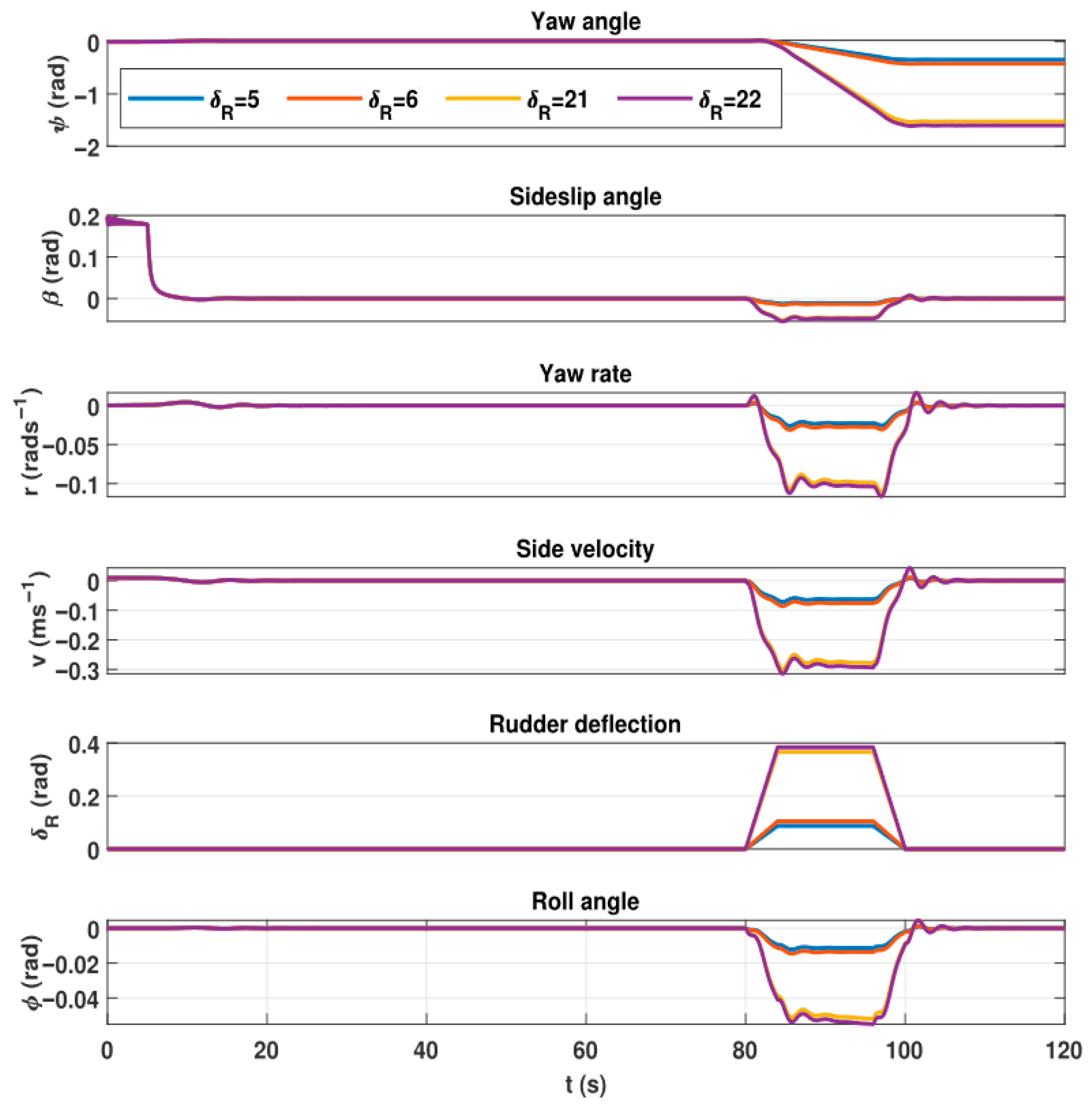
A rudder deflection is applied after 80 s of flight for 15 s, while the airship is in horizontal motion. The results for a 120 s simulation run of lateral motion variables are plotted against time. A rapid change in yaw rate can be seen, as expected, since the rudder input excites the fast yaw subsidence mode. The change in sideslip angle was comparatively slower with β m a x under 10. This observation has increased confidence in the model response. Moreover, a fascinating fact was observed for the roll oscillation mode. While air vehicles or any other ground vehicles turn, they bank at some angle to retain a certain degree of stability. This fact is observed in the simulation and can be seen in the plot (vi) of Figure 7. When rudder deflection is applied, the airship’s roll angle increases and attains a maximum value of about 10 degrees. The roll angle attains its initial value when the deflection is removed.
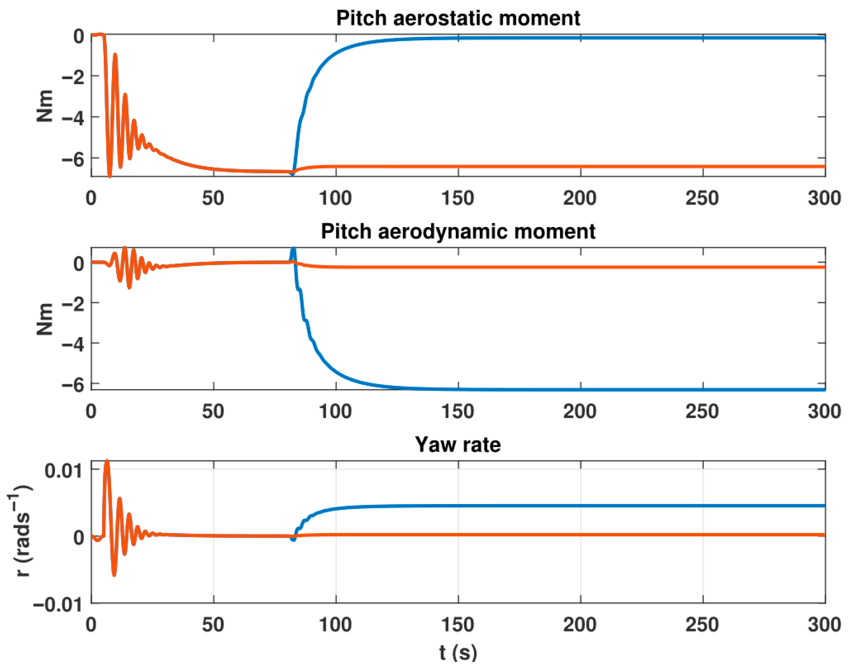
The sensitivity of the response to the magnitude of the input is assessed by running a different simulation under the same environmental conditions but with 6 degrees of rudder deflection. An increase in deflection angle introduced an increase in all lateral motion variables. However, the overall behaviour of the response was the same. The plots reveal that in the small perturbation case, a 20% change in input produces approximately a 20% change in response. For the same experiment conditions, a large perturbation case is tested. This time, 21 degrees and 22 degrees of rudder deflections are applied for 15 s, and the simulation is executed for 120 s. The overall response is of the same kind, though there are certain differences. The yaw rate increases linearly while the input is being applied. If rudder deflection is continuously applied for 300 s of a simulation run, it obtains its steady-state value after 126 s, as shown in Figure 8. This is because at large rudder deflection angles, the roll angle increases to 3 degrees. This angle induces a significant percentage change in pitch aerodynamic moment and pitch aerostatic moment. The pitch aerodynamic moment changes to 24% and the pitch aerostatic moment changes to 41%, as shown in Figure 9. The significant change in the airship pitch aerodynamic and aerostatic moments induces an increase in the angle of attack up to 0.3 degrees. This excites the longitudinal dynamics of the airship, and eventually, the dynamic coupling of motion variables appears in the yaw rate response. It is observed that the longitudinal modes are slower than the lateral modes. So, at large rudder deflections, the excitation of longitudinal modes affects the response of the yaw rate. Eventually, the yaw rate response slows down and obtains its steady-state value after 45 s, whereas in the small perturbation case, it was constant. This was because the slight rudder deflection produced a small roll angle. The percentage change in pitch aerodynamic and aerostatic moments in the small perturbation case was small. For example, the percentage change in pitch aerodynamic moment was 91% and the pitch aerostatic moment was 0.044%. Therefore, this small change is insufficient to excite longitudinal dynamics. The angle of attack for 50 degrees of rudder deflection remains 0.012 degrees. So, it does not excite the longitudinal dynamics, and the coupled response for the yaw rate is not observed. In conclusion, the considerable amplitude input has resulted in a nonlinear response exhibited by the vehicle.

4.3. Case 3: Response to the Thruster Input

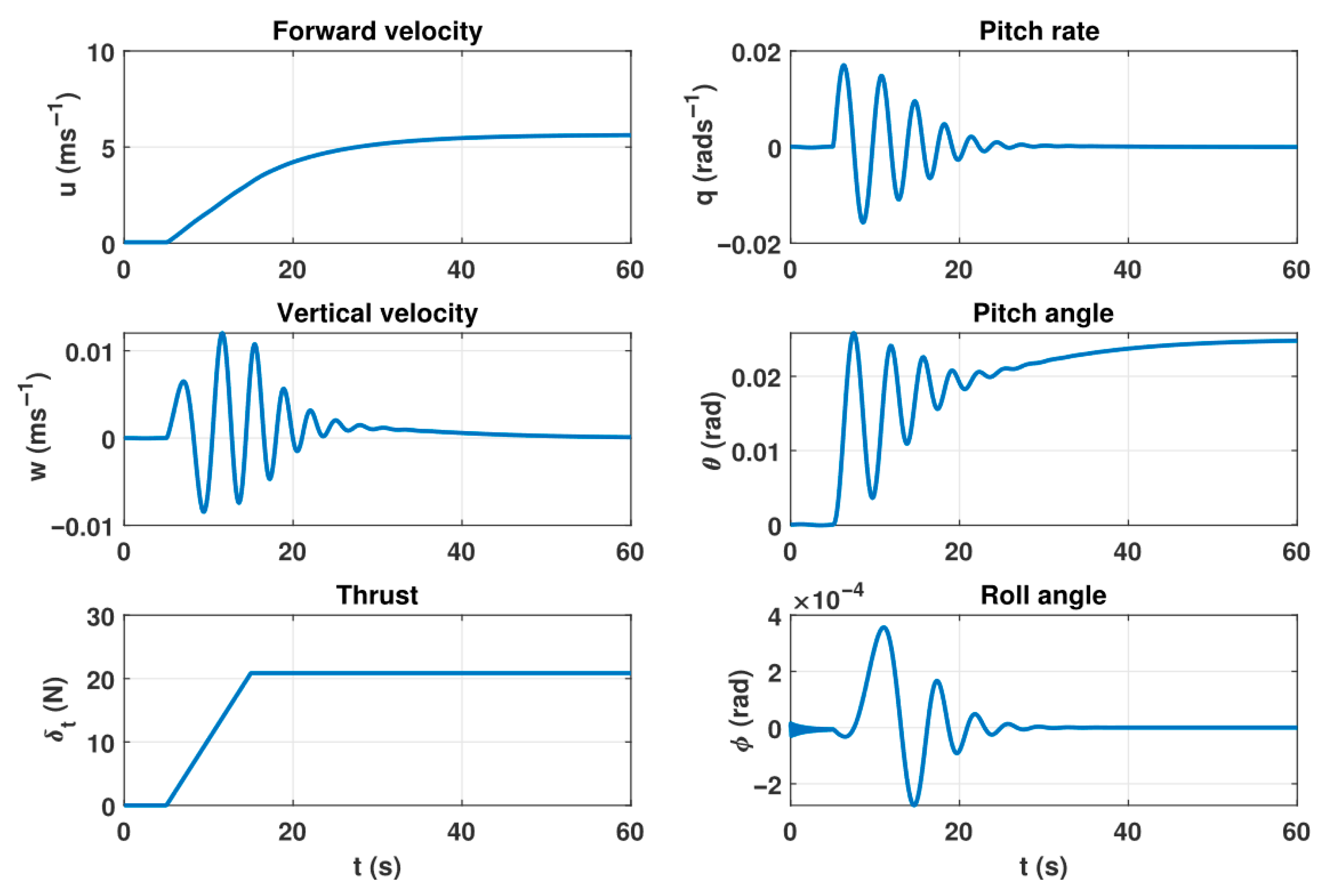
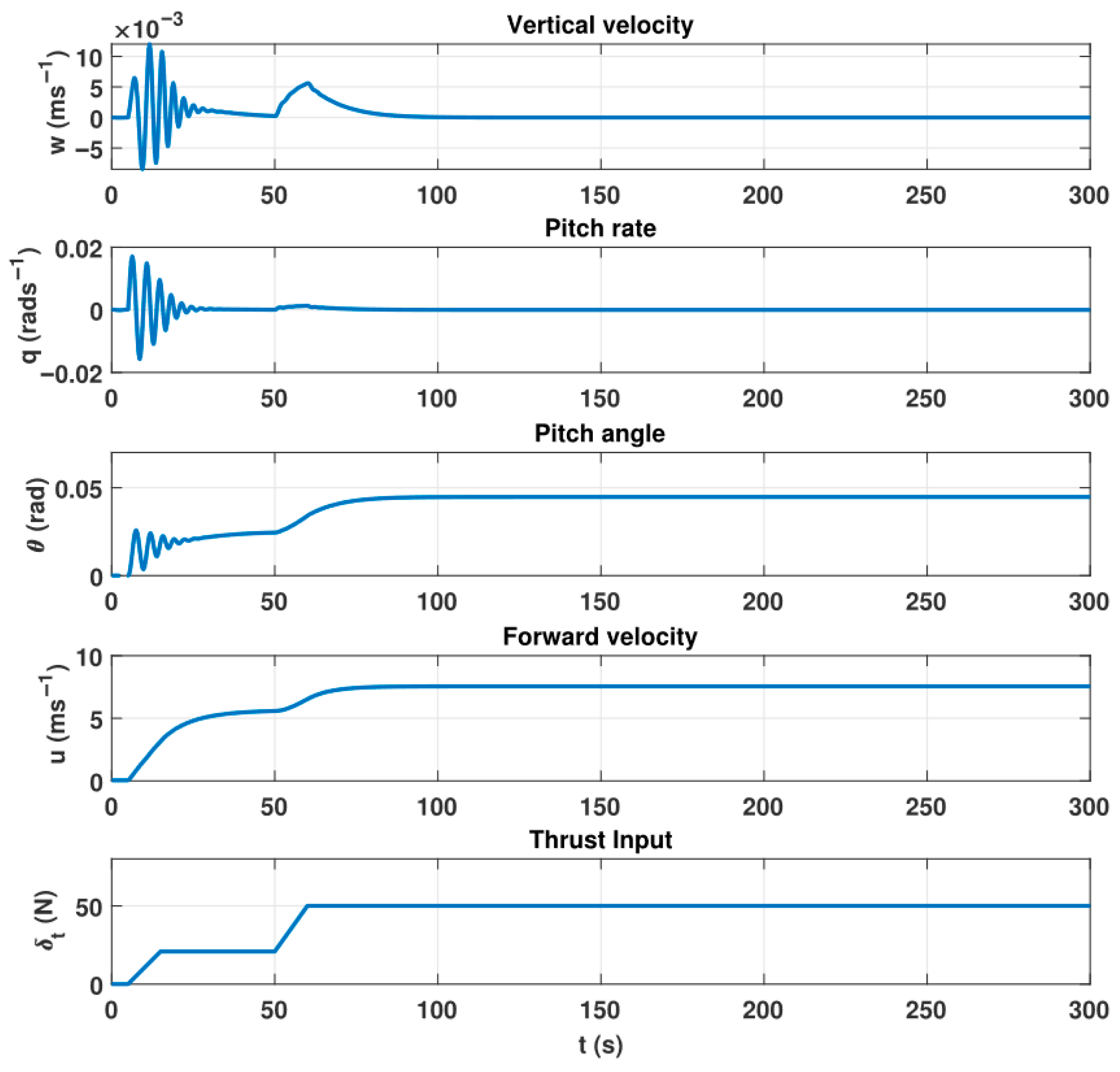
The sensitivity of the airship motion variables to thruster commands is investigated by conducting a separate simulation experiment. It is assumed that the airship is initially in stationary mode. After 5 s of a simulation run, it is subjected to a thrust command. This input excites longitudinal motion variables and pitching because the thrust vector acts below the centre of mass. For this experiment, the same outputs of interest are considered as those in the elevator case.
After the application of the input command, the airship starts moving forward with increasing horizontal velocity ( u ). Initially, the airship faces oscillatory motion, where its nose experiences up–down movements. This is because the airship is a lighter-than-air vehicle, and its CG is on the line below the CV. Such a location of the CG is responsible for this type of pendulum mode. In Figure 10, the pendulum mode is evident from the decaying oscillation of pitch rate. The pitch angle initially fluctuates and then retains a positive value. The steady-state value of pitch rate reveals that, as a consequence of a constant amount of thrust, the airship keeps its motion in the forward direction with a slight nose elevation (it does not depend on elevator input). It can be brought to zero by applying vector thrusting or elevator deflection, but this simulation case only considers the forward thrusting.

4.4. Validations of Simulation Results

4.4.1. Comparison with YEZ-2A

The credibility of the simulation results is increased by comparing the response of motion variables with the results available in the literature. Our results are similar to the experiments performed by Gomes on the YEZ-2A airship. He reported the response of the airship for elevator, rudder, and thruster type of inputs under neutral buoyancy and ISA conditions. The YEZ-2A airship is larger, but its fineness ratio is approximately the same as that of the UETT airship. Moreover, the results available for YEZ-2A have been obtained for the same kind of input as was used in this thesis. By comparing the results of both airships, the following observations are made:
  • Application of elevator deflection has excited the longitudinal mode of the airship motion as expected. The same sort of observation is made for the YEZ-2A airship as reported by Gomes in his work in Figures (6.2.1-4) [5]. The elevator deflection has produced a change in pitch angle. After the removal of input, the pitch angle was brought to its initial value. For the YEZ-2A airship, a similar pitch rate response is found.
  • Investigation of small perturbation and significant perturbation cases is made. For a large perturbation, a nonlinear response is observed. For both types of inputs, the observed overall behaviour and sensitivity of the response were the same as seen for the YEZ-2A airship.
  • Rudder input has excited the fast yaw subsidence mode, and it is responsible for introducing the lateral motion. After removal of the input, the yaw angle remains at a fixed value previously attained due to the application of the input. However, for YEZ-2A, the yaw angle does not settle at a fixed value, and a residual yaw rate remains. Furthermore, it is noted that a vestigial turn rate exists even before the application of rudder input. It reflects that the wind tunnel data has a certain amount of yaw force and yaw rate for zero sideslip angles. This fact may occur even for a large airship model in wind tunnels. This is because perfect longitudinal symmetry is virtually unattainable in wind tunnel experiments. However, this fact is not observed in our case. In our case, after the removal of the input, the yaw rate attains its initial value.
  • It is a common observation that when a vehicle turns, it banks with a certain angle to confine itself within a stability region. This banking provides the necessary centrifugal force. This fact is observed for the UETT airship simulation, as shown in Figure 6, which shows the airship attaining a constant amount of roll angle after the application of rudder input. The simulation results for the YEZ-2A airship, as shown in Figures (6.3.1-4) [5], also indicate this fact.
  • Sensitivity of the response to the variation in the amplitude of the perturbation is observed. For 220 degrees of rudder deflection, a nonlinear increase in yaw angle is seen while the input is being applied. This fact was prominent for YEZ-2A.
  • A pendulum mode is observed in the simulation when thrust input is applied. This is because the airship’s centre of gravity position is at some distance below the centre of buoyancy. This mode is excited in YEZ-2A. They have devised a separate an experiment for it where, while the airship is hovering, an elevator input is applied for a short interval as shown in Figure (5.7) [5].

4.4.2. Comparison of Eigenvalues

Airship eigenvalues of longitudinal and lateral models are obtained. The names of these eigenmodes correspond to the physical behaviour of the aerodynamic body. They are commonly called surge, heave, pendulum, sideslip subsidence, yaw subsidence, and roll oscillation modes in the air vehicle literature. Sideslip and yaw subsidence modes for the UETT airship have damped oscillatory behaviour. The eigenvalues are calculated using the following formula:
λ I A = 0
where λ represents the eigenvalues, I represents the identity matrix, and A represents the system matrix. The magnitude sign ‘ |   | ’ represents the determinant of the matrix. For finding the longitudinal eigenvalues, the following formula is used:
λ I A l o n = 0
where A l o n represents the system matrix for the longitudinal dynamics of an airship. For finding the eigenvalues of lateral dynamics, the following formula is used:
λ I A l a t = 0
where A l a t represents the system matrix for the lateral dynamics of an airship. The resultant eigenvalues are given in Table 6.
Table 6 also shows the eigenvalues of the airship linearised longitudinal and lateral models that are identified from flight data [17]. By comparing the eigenvalues for the simulation model and the experimental model, it can be inferred that both behave similarly. Both models exhibit damped oscillatory responses for sideslip and yaw subsidence modes, and both have slower surge modes compared to the longitudinal heave mode. However, their damped frequency differs by a factor of five because, while obtaining the experimental data, the perfect trimmed flight condition was not maintained. During the experimentation, sails were used to keep the airship’s altitude constant, which impacted the experimental data. These observations have increased confidence in our developed simulation model for the UETT airship.

4.4.3. Comparison of Surge, Heave, Sideslip Subsidence, and Yaw Subsidence Eigenmodes with Other Airships

When compared with other airships in the literature, the UETT airship does not match any one with respect to its inertia and other geometrical properties. It represents a separate category of airships due to its distinct geometry and mass/inertia. The comparison data is given in Table 7.
The surge, heave, sideslip, subsidence, and yaw subsidence modes are identified by conceiving specific experiments that are adequate for exciting the airship longitudinal and lateral motion variables. This is achieved by applying commands to the nonlinear simulation model of the UETT airship that excite the modes of interest.
To demonstrate the surge mode, an experiment is conceived where the airship is allowed to fly for 50 s in level flight under neutral buoyancy conditions and having a trimmed velocity of 5.5 ms−1. Then a 110% change in the thrust input is applied, and the simulation is allowed to run for 300 s. The data for longitudinal motion variables are gathered and plotted in Figure 11. It can be seen that the forward velocity obeys an exponential law as a consequence of a perturbation in the input. After 9 s of the applied change, the forward velocity achieves 63% of the final steady-state value. Therefore, it can be adequately said that the vehicle behaviour is dominated by surge mode. The time constant of the response can be used to calculate the eigenvalue of the surge mode. For the current simulation case, a 9 s time constant value is observed, so the surge mode eigenvalue will be
S s u r g e = 1 τ s u r g e = 1 9 = 0.1
The airship’s hover mode is demonstrated by conducting an experiment where the airship is allowed to fly for 150 s in a straight and level flight under neutral buoyancy conditions and at a flight speed of 5.5 ms−1. Then, an elevator perturbation is applied for about 25 s. Figure 12 shows the results. After 11 s, the pitch angle has reached 63% of its steady-state value. Therefore, the vehicle behaviour is dominated by the heave mode. The time constant of the response can be calculated from the eigenvalue of the heave mode. For the current simulation case, an approximately 5.5 s value is observed for the time constant, so the heave mode eigenvalue will be
S h e a v e = 1 τ h e a v e = 1 5.5 = 0.18
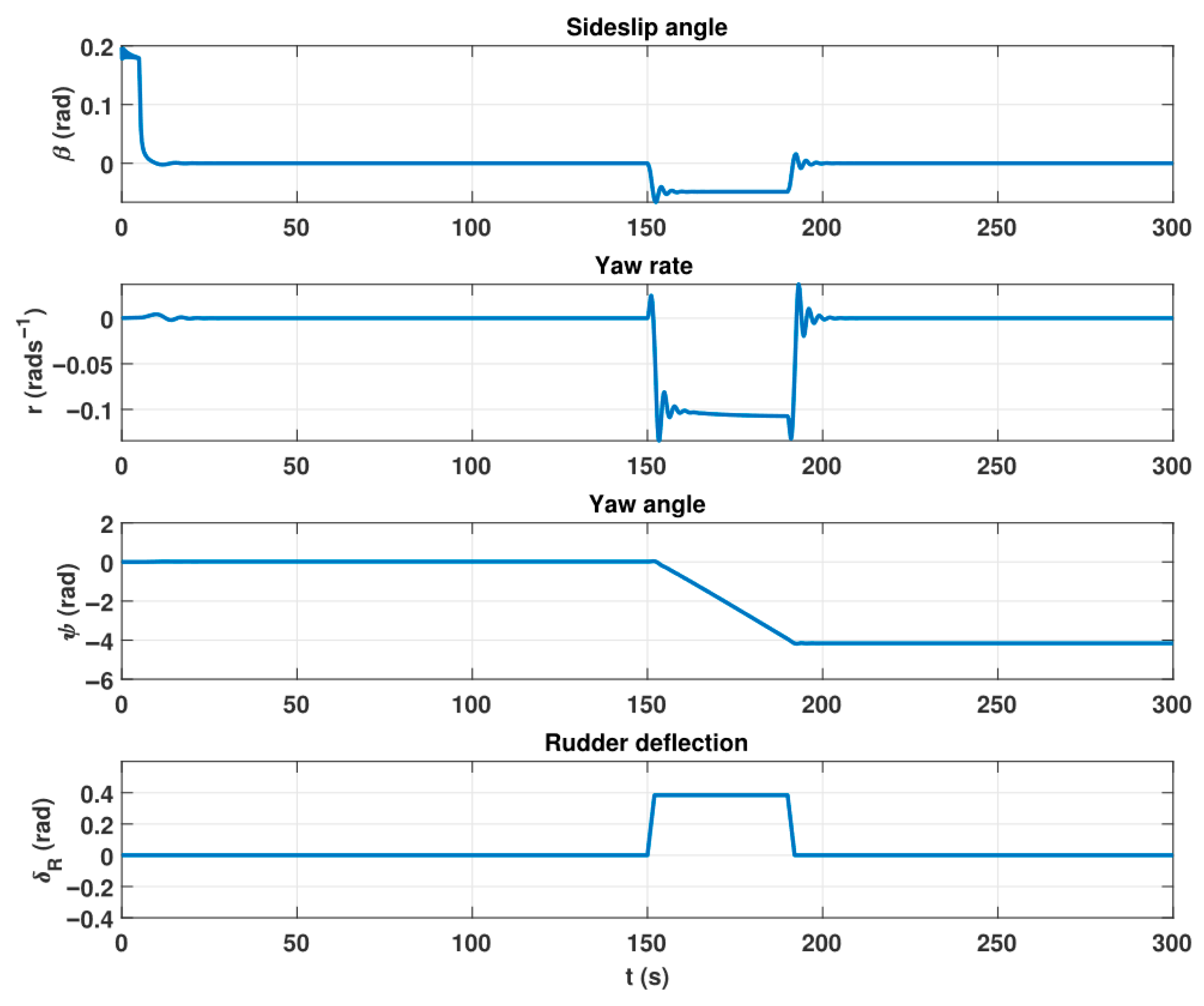
In order to demonstrate the sideslip and yaw subsidence mode, a single experiment is conceived where the airship is provided with rudder deflection for about 40 s. The response of sideslip angle, yaw rate, and yaw angle are recorded against time, and the results are summarised in Figure 13. It can be seen that during the application of input, the desired variables achieve their steady-state values. Therefore, the vehicle lateral eigenmode is appropriately excited by the designed piloted commands, and both sideslip and yaw rate follow the decaying oscillation pattern. This means that both modes are dominated by oscillatory behaviour. From the transient response characteristics, the damping ratio and natural frequency of the modes are calculated using the following relations:
% O v e r s h o o t = e ζ π 1 ζ 2 × 100
T p = π ω n 1 ζ 2
The calculated peak time ( T p ) and %Overshoot are 1.8 s and 53%, respectively. After manipulating Equations (42) and (43), the values of 0.19 and 1.77 rads−1 are obtained for damping ratio ( ζ ) and natural frequency ( ω n ), respectively. Eigenvalues for the above discussed characteristic modes of motion for the UETT airship are found and summarised in Table 8. For the purpose of comparison, the eigenvalues for same mode of motion for other airships are also given in Table 8.
It is evident from the data that the longitudinal mode of motion of the UETT airship is comparable to that of the existing airships. As expected, the surge mode is slower as represented. With a negative eigenvalue, the heave mode is relatively faster. However, oscillatory behaviour can be seen in the UETT airship’s sideslip and yaw subsidence modes. For all other airships, these modes are stable, except for the LOTTE airship. The modes possess a decaying exponential type of characteristic. In the UETT airship response analysis, this type of behaviour is not observed. However, the oscillatory characteristics in the yaw subsidence mode are also observed in the experimental flight of the UETT airship [15], which strengthens the observations.

5. Conclusions

In this paper, an airship dynamic model is obtained using Newtonian mechanics. Laws of motion are applied in an inertial frame, and the inertial-to-local frame transformation is used for the derivation of 6-DOF dynamic model expressions in the body frame. The aerodynamic modelling expressions are based on the airship’s geometric parameters, and they are adopted from Muller’s work. The obtained equations of motion are implemented in a MATLAB/Simulink environment, and the simulator performance is assessed by applying thruster, rudder, and elevator inputs. The results indicate that thruster and elevator inputs excite the airship longitudinal motion variables such as pitch, forward velocity, and vertical velocity. The rudder input excites the airship lateral modes. The results are closely related to the observations made by Gome’s experimental and simulation flight data for YEZ-2A. These observations have validated the response of the UETT airship simulation setup, increasing our confidence in the developed simulator.

Author Contributions

M.W. Conceptualization, Data curation, Formal analysis, Investigation, Writing—original draft, Writing—review & editing, Methodology, Software. A.A. Project administration, Resources, Supervision, Validation, Writing—review & editing. M.U.S. Funding acquisition, Writing—review & editing, Resources, Visualization. All authors have read and agreed to the published version of the manuscript.

Funding

This research received no external funding.

Data Availability Statement

The original contributions presented in this study are included in the article. Further inquiries can be directed to the corresponding author(s).

Conflicts of Interest

The authors declare no conflict of interest.

References

  1. Rufford, T.E.; Chan, K.I.; Huang, S.H.; May, E.F. A review of conventional and emerging process technologies for the recovery of helium from natural gas. Adsorpt. Sci. Technol. 2014, 32, 49–72. [Google Scholar]
  2. Miller, S.H.; Fesen, R.; Hillenbrand, L.; Rhodes, J.; Baird, G.; Blake, G.; Booth, J.; Carlile, D.E.; Duren, R.; Edworthy, F.G.; et al. Airships: A new horizon for science. arXiv 2014, arXiv:1402.6706. [Google Scholar]
  3. Gayrard, J.-D. System for Telecommunications by Network of Stationary High-Altitude Platforms and Drifting Balloons. U.S. Patent App. 15/919,659, 27 September 2018. [Google Scholar]
  4. Joshi, M.; Chatterjee, U.; Adak, B.; Tiwari, R.; Mandlekar, N.; Chouhan, S.; Butola, B.S. A critical review on the development and technology of aerostat and airship hull material. J. Text. Inst. 2025, 116, 483–498. [Google Scholar]
  5. Gomes, S.B.V. An Investigation into the Flight Dynamics of Airships with Application to the YEZ-2A. Ph.D. Thesis, Cranfield University, Cranfield, UK, 1990. [Google Scholar]
  6. Solaque, L.; Lacroix, S. Airship control. In Multiple Heterogeneous Unmanned Aerial Vehicles; Springer: Berlin/Heidelberg, Germany, 2007; pp. 147–188. [Google Scholar]
  7. Wasim, M.; Ali, A. Airship aerodynamic model estimation using unscented Kalman filter. J. Syst. Eng. Electron. 2020, 31, 1318–1329. [Google Scholar] [CrossRef]
  8. Wasim, M.; Ali, A. Estimation of airship aerodynamic forces and torques using extended Kalman filter. IEEE Access 2020, 8, 70204–70215. [Google Scholar] [CrossRef]
  9. Wasim, M.; Ali, A.; Choudhry, M.A.; Saleem, F.; Shaikh, I.U.H.; Iqbal, J. Unscented Kalman filter for airship model uncertainties and wind disturbance estimation. PLoS ONE 2021, 16, e0257849. [Google Scholar] [CrossRef] [PubMed]
  10. Wasim, M.; Ali, A.; Shaikh, I.U.H.; Awan, M.M.A. Estimation of airship states and model uncertainties using nonlinear estimators. Mehran Univ. Res. J. Eng. Technol. 2024, 43, 55–69. [Google Scholar] [CrossRef]
  11. Wasim, M.; Ali, A.; Choudhry, M.A.; Shaikh, I.U.H.; Saleem, F. Robust Design of Sliding Mode Control for Airship Trajectory Tracking with Uncertainty and Disturbance Estimation. J. Syst. Eng. Electron. 2024, 35, 242–258. [Google Scholar] [CrossRef]
  12. Mazhar, M.F.; Abbas, S.M.; Wasim, M.; Khan, Z.H. Bayesian Identification of High-Performance Aircraft Aerodynamic Behaviour. Aerospace 2024, 11, 960. [Google Scholar] [CrossRef]
  13. Mazhar, M.F.; Wasim, M.; Abbas, M.; Riaz, J.; Swati, R.F. Aircraft System Identification Using Multi-Stage PRBS Optimal Inputs and Maximum Likelihood Estimator. Aerospace 2025, 12, 74. [Google Scholar] [CrossRef]
  14. Mazhar, M.F.; Wasim, M.; Abbas, M.; Shafi, I.; Riaz, J.; Kim, T.-H.; Ashraf, I. Aerodynamic model identification of supersonic aircraft using Bayesian approach-based Box–Jenkins structure. Alex. Eng. J. 2025, 127, 472–485. [Google Scholar] [CrossRef]
  15. Ahsan, M.; Choudhry, M.A. System identification of an airship using trust region reflective least squares algorithm. Int. J. Control Autom. Syst. 2017, 15, 1384–1393. [Google Scholar] [CrossRef]
  16. Mazhar, F.; Choudhry, M.A.; Shehryar, M. Nonlinear auto-regressive neural network for mathematical modelling of an airship using experimental data. Proc. Inst. Mech. Eng. Part G J. Aerosp. Eng. 2019, 233, 2549–2569. [Google Scholar] [CrossRef]
  17. Saeed, A.; Liu, Y.; Shah, M.Z.; Wang, L.; Wang, Q.-G. Sliding mode lateral guidance and control of finless airship. J. Aerosp. Eng. 2022, 35, 04021131. [Google Scholar] [CrossRef]
  18. Meng, Z.; Ma, J.; Zhang, T. Adaptive fast trajectory tracking control for the airship based on prescribed performance. Proc. Inst. Mech. Eng. Part G J. Aerosp. Eng. 2024, 238, 893–908. [Google Scholar] [CrossRef]
  19. Stockbridge, C.; Ceruti, A.; Marzocca, P. Airship research and development in the areas of design, structures, dynamics and energy systems. Int. J. Aeronaut. Space Sci. 2012, 13, 170–187. [Google Scholar] [CrossRef]
  20. Ashraf, M.Z.; Choudhry, M.A. Dynamic modeling of the airship with Matlab using geometrical aerodynamic parameters. Aerosp. Sci. Technol. 2013, 25, 56–64. [Google Scholar] [CrossRef]
  21. Fossen, Y.T.I. Handbook of Marine Craft Hydrodynamics and Motion Control; John Wiley & Sons: Hoboken, NJ, USA, 2011. [Google Scholar]
  22. Mueller, L.J.; Paluszek, M.; Zhao, Y. Development of an aerodynamic model and control law design for a high altitude airship. In Proceedings of the AIAA 3rd “Unmanned Unlimited” Technical Conference, Workshop and Exhibit, Chicago, IL, USA, 20–23 September 2004; p. 6479. [Google Scholar]
Figure 1. Airship modelling ways depending upon the requirements.
Processes 13 02688 g001
Figure 2. The coordinate system of an airship O E X E Y E Z E represents the inertial frame of reference and O b x b y b z b represents the body fixed frame of reference.
Processes 13 02688 g002
Figure 3. Geometrical parameters of the ellipsoidal airship.
Processes 13 02688 g003
Figure 4. UETT airship simulation setup block diagram.
Processes 13 02688 g004
Figure 5. Affect of elevator deflection ( δ E in degrees) on forward velocity of the airship.
Processes 13 02688 g005
Figure 6. Test case 1: Effect of elevator deflection ( δ E in degrees) on the longitudinal motion variables.
Processes 13 02688 g006
Figure 7. Test case 2: Effect of rudder deflection on the airship lateral motion variables.
Processes 13 02688 g007
Figure 8. Test case 2: Effect of rudder deflection on the airship yaw rate when the input is being applied for 300 s of a simulation run.
Processes 13 02688 g008
Figure 9. Test case 2: Effect of rudder deflection on the airship pitch aerostatic moment, pitch aerodynamic moment, and angle of attack when the input is being applied for 300 s of a simulation run.
Processes 13 02688 g009
Figure 10. Test case 3: Effect of the application of thruster input on airship motion variables.
Processes 13 02688 g010
Figure 11. UETT airship longitudinal surge mode identification.
Processes 13 02688 g011
Figure 12. UETT airship longitudinal heave mode identification.
Processes 13 02688 g012
Figure 13. UETT airship lateral sideslip and yaw subsidence mode identification.
Processes 13 02688 g013
Table 1. Airship mass matrix parameters.
ParameterValueParameter Value
m 24.073 kg J x 11.6513 kgm2
m x 6.443 kg J y 176.321 kgm2
m y 48.24 kg J z 176.321 kgm2
m z 48.24 kg J z x 0.1 kgm2
a x 0.33 m a z 0.976 m
b x 0.33 m b z 0 m
B f 273.81 N W 273.81 N
Table 2. Values of added mass and inertia terms.
ParameterValueParameterValue
X u ˙ −2.37 kg L p ˙ 0 kgm
Y v ˙ 24.167 kg N p ˙ 0 kgm
X q ˙ 0 kgm M q ˙ 0 kgm
Y p ˙ 0 kgm L r ˙ 0 kgm
Y r ˙ 0 kgm L v ˙ 0 kgm
Z q ˙ 0 kgm M u ˙ 0 kgm
N v ˙ 0 kgm M w ˙ 0 kgm
Table 3. Airship geometrical parameters.
ParameterValueParameter Value
V 22.808 m3 l f 1 2.3 m
d 2.2 m l f 2 2.96 m
L 9 m l f 3 1.18 m
b 1.1 m l g x 0.55 m
a 1 3.9 m S h 8.04 m2
a 2 5.1 m S f 9 m2
x c v 4.43 m S g 1 m2
l h 6.43 m l g z 1.40 m
Table 4. Airship aerodynamic model coefficients obtained from wind tunnel experiments [5]. These are valid for an airship with cylindrical ratio of 4.0.
ParameterValueParameter Value
K 1 0.085 C L δ f 5.73
K 2 0.865 C L α f 1.24
C D h 0 0.025 η f 0.29
C D f 0 0.006 η k 1.19
C D g 0 0.01 I 1 0.3564
C D c h 0.5 I 2 −0.1758
C D c f 1.0 J 1 0.9315
C D c g 1.0 J 2 −0.1086
Table 5. Airship simulator evaluation under test cases.
CaseInput OutputFlight ConditionInput Application Time
Case 1Elevator θ ,   q ,   α , ω ,   p Z Neutral buoyancy, 67 m altitude150 s
Case 2Rudder ψ , r , β , v , ϕ , p Neutral buoyancy, 67 m altitude80 s
Case 3Thruster u , v , ω , p , q , r Neutral buoyancy, 67 m altitude5 s
Table 6. Eigenvalues of longitudinal and lateral eigenmodes of UETT airship.
LongitudinalSurgeHeavePendulum
Linearised simulation model−0.1012−0.2106−0.5530 ±   3.1667 i
Experimental−0.1797−0.3155−0.115 ± 0.6458 i
LateralSideslip
subsidence
Yaw subsidenceRoll oscillations
Linearised simulation model−0.3956 ± 2.4145 i −0.7400 ± 4.7032 i
Experimental−0.4934 ± 1.4238 i −0.0844 ±   0 .0527 i
Table 7. Parameters of different airships that exist in the literature.
AirshipLength (m)Maximum Diameter (m)Mass (Kg)Fineness Ratio
YEZ-2A129.932868164.047
AURORA93203
JPL AEROBOT11.432.43842.54.68
LOTTE154136.83.75
UETT92.2284.09
Table 8. Comparison of eigenvalues of UETT airship simulation and experimental data with different airships existing in the literature.
AirshipSurgeHeaveSideslip SubsidenceYaw Subsidence
YEZ-2A−0.0056−0.0392−0.0315−0.232
AURORA−0.1426−3.7819−0.6080−4.9182
JPL AEROBOT−0.1198−0.1971−0.6005−0.8745
LOTTE−0.07−1.15+0.234−1.24
UETT simulation−0.1−0.18−0.342 ± 1.736 i
UETT linearised simulation model−0.1012−0.2106−0.3956 ±   2 .4145 i
UETT experimental−0.1797−0.3155−0.4934 ± 1.4238 i
Disclaimer/Publisher’s Note: The statements, opinions and data contained in all publications are solely those of the individual author(s) and contributor(s) and not of MDPI and/or the editor(s). MDPI and/or the editor(s) disclaim responsibility for any injury to people or property resulting from any ideas, methods, instructions or products referred to in the content.