Article

Comparative Study of Variable-Flow Gas Injection Patterns on CH4 Diffusion Dynamics: Experimental Insights into Enhanced Coalbed Methane Recovery

1
School of Safety Science and Emergency Management, Wuhan University of Technology, Wuhan 430000, China
2
School of Resources and Safety Engineering, Henan University of Engineering, Zhengzhou 450000, China
3
School of Building Environment Engineering, Zhengzhou University of Light Industry, Zhengzhou 450000, China
4
School of Mine Safety, North China Institute of Science and Technology, Langfang 065000, China
*
Author to whom correspondence should be addressed.
Processes 2025, 13(8), 2642; https://doi.org/10.3390/pr13082642
Submission received: 17 June 2025 / Revised: 20 July 2025 / Accepted: 13 August 2025 / Published: 20 August 2025
(This article belongs to the Section Energy Systems)

Abstract

Variable-flow displacement has been effectively used to enhance oil recovery; however, it has rarely been investigated for coalbed methane production, and the CH4 diffusion laws in this process are not clear. In this paper, we carried out a study on the CH4 diffusion law in the bidirectional diffusion process displaced by variable-flow gas injection. The emission and desorption quantity of CH4 under variable-flow gas injection, the displacement effect under the principle of equal time and quantity, and the applicability of the CH4 diffusion model for the bidirectional diffusion process were analyzed. The results indicate that the variable-flow injection modes emit more CH4 compared to constant flow injection. The CH4 emission and desorption quantities for each injection mode are as follows: step-changed > sinusoidal-changed > constant flow. Secondly, the order of CH4 emission and desorption quantity in each gas injection mode is as follows: step-changed > sinusoidal-changed > constant flow. When CO2 is the injection gas source, the outlet CH4 emission and desorption quantity are larger than N2 injection. Thirdly, through the analysis of the principle of equal time and equal quantity, the variable-flow injection modes consume less gas for each volume of emitted CH4, resulting in a more effective displacement. Finally, the diffusion fitting effect of the bidisperse model for CH4 in the bidirectional diffusion process is better than that of the unipore model, and the bidisperse diffusion model can better fit the mt/m curve of CH4 diffusion during the variable-flow gas injection replacement process.

1. Introduction

Gas injection displacement has emerged as a globally recognized effective technology for enhancing coalbed methane (CBM) production, demonstrating significant improvements in CBM recovery rates [1,2,3,4,5]. More recently, researchers have successfully applied this technology to mine gas disaster mitigation, with field applications showing promising results [6,7]. The predominant gas injection agents include N2 [8,9,10], CO2 [11,12,13], and their binary gas mixtures [14,15]. CO2 demonstrates superior adsorption affinity in coal compared to CH4 [16,17,18,19], owing to its stronger molecular interactions with coal matrices. When injected, CO2 preferentially occupies CH4 adsorption sites through competitive adsorption mechanisms, thereby displacing and promoting CH4 desorption. Conversely, N2 primarily functions through physical displacement in coal fractures. As an inert gas with lower adsorption capacity, N2 reduces CH4 partial pressure within the pore system while establishing concentration gradients that enhance CH4 diffusion and liberation [10,20,21]. Therefore, the whole displacement process can be regarded as a comprehensive process for co-adsorption of injection gas and CH4 in the matrix of coal pores, in which the injected gas and CH4 are mixed in the fracture network of the coal seam, the injected gas diffuses from the fracture into the matrix of coal, and the desorbed gas diffuses from the matrix to the fracture. Because the diffusion of injected gas and CH4 is a migration process along the same cleats but in opposite directions, it is referred to in this study as a “bidirectional diffusion process”, which is different from the “unidirectional diffusion process” of single gas in coal.
In the previous research, most scholars have done a lot of work on the displacement process under the condition of constant flow gas injection by controlling the gas injection type [22,23], gas injection pressure [24,25,26], gas injection time [27], degree of coal metamorphism [28,29], coal sample gas pre-adsorption pressure [30,31], and stress conditions [32,33]. A variety of displacement conditions are simulated, and the displacement mechanism and the permeability evolution law are analyzed under each of the conditions. For the final adsorption state of injected gas and gas, that is, the law of “competitive adsorption”, scholars have also done a lot of research through quasi-static adsorption experiments, considering gas types [34,35], coal rank [36,37], mixed gas ratio [38], coal sample humidity [36,39], temperature [40], and so on. In addition, the previous research on the gas diffusion law connecting adsorption in pores and seepage in fractures mainly focused on the single gas diffusion mechanism and also formed widely accepted characterization models such as the unipore diffusion model [41,42], bidisperse diffusion model [43,44,45], and dispersion diffusion model [46,47]. In conclusion, scholars have done a lot of research on the change of seepage law and competitive adsorption characteristics in the process of gas injection displacement, and achievements in the research on the diffusion characteristics of single gas in coal were made, but there are few experimental studies on the law of the bidirectional diffusion process in gas injection displacement.
N2 and CO2 injection displace coal seam gas, and water injection [48] and gas injection [49,50] in oil production are technically “injection-production” displacement types. Many similar research results indicate that in the “injection-production” displacement, the variable-flow technology can achieve better gas and liquid utilization efficiency and displacement performance. The research on variable-flow injection-production [51,52,53] is widely used in the oil industry, and its displacement effect and injection source utilization rate are better than those of constant flow injection, but it is rare to apply the variable-flow gas injection method to the research of coalbed methane production increase or gas disaster prevention. Note that the previous studies are based on the boundary conditions of constant flow gas injection/quasi-static adsorption, and the special flow field environment in the coal body caused by the variable-flow gas injection displacement also poses some key problems that cannot be solved by the previous research findings, such as (1) whether the bidirectional diffusion process of CH4 can be described by the unidirectional diffusion law under the condition of variable-flow gas injection displacement, and whether the diffusion coefficient of each gas is the same as that of its unidirectional diffusion; (2) the displacement effect of gas injection under the condition of variable-flow lacks quantitative description compared with that of constant flow gas injection.
In this study, a custom-designed experimental system was developed to investigate bidirectional gas diffusion under variable-flow injection conditions. The dynamic characteristics of CH4 diffusion during bidirectional displacement processes under variable-flow conditions were systematically investigated. A bidirectional diffusion model was developed, with subsequent quantitative analysis of CH4 diffusion coefficient variations under transient flow conditions. Comparative evaluation of displacement efficiencies between variable-flow and constant-flow regimes was performed through parametric analysis. The results provide theoretical support for optimizing in situ CBM drainage operations and enhancing gas recovery efficiency.

2. Experimental Samples, Apparatus, and Procedures

2.1. Preparation of Coal Sample

Coal samples were collected from the 13# coal seam at Xiaojiawa Coal Mine (located in Lvliang City, China). The average thickness of the seam is 12.02 m, which is a relatively stable and mineable coal seam across the entire area. The roof was dominated by sandy mudstone, followed by mudstone, and the bottom was dominated by mudstone, followed by sandy mudstone. The coal samples are gas coals with a low degree of metamorphism. The gas content of the No. 13 coal seam ranges from 1.65 to 2.65 m3/t. Despite the relatively low gas content per tonne of coal, the high-intensity mining operations have resulted in significant gas emissions. Simultaneously, due to the low porosity (only 4.82%), conventional drainage methods cannot effectively reduce the gas content. The location of coal samples is shown in Figure 1. Fresh coal samples were wrapped in plastic, sealed, and transported to the laboratory, where they were crushed and sieved to obtain coal particles with a diameter of 1–3 mm, dried, and used for experiments. The basic parameters of the coal samples are tabulated in Table 1.

2.2. Experimental Methods

2.2.1. Experimental Apparatus

A bidirectional diffusion apparatus was designed to study the diffusion behavior of CH4 under variable-flow gas injection conditions, as illustrated in Figure 2. The apparatus includes a gas injection system, a gas injection flow control and monitoring system, a thermostat box, a coal sample tank, a back-pressure valve, a gas concentration sensor, a vacuum pump, and data acquisition computer, and a gas injection steel pipe. The gas injection system consists of high-pressure cylinders (He, CH4, N2, and CO2), a six-way valve, and a relief valve to control the pressure and composition of the injected gas. The flow control and monitoring system consists of two flow-meters, installed at both the inlet and outlet ends of the coal sample tank. The inlet flow-meter controlled the gas injection flow rate, while the outlet flow-meter monitored the flow rate of the gas leaving the tank. The thermostat box was used to maintain a constant temperature in which equipment such as inlet and outlet flow-meters, coal sample tank, back-pressure valve, gas pressure sensor, stop valve, etc., was placed. The internal volume of the coal sample tank was approximately 800 mL. Quartz chips were positioned at both ends of the canister to facilitate uniform dispersion of the injected gas. The data acquisition system collected experimental data on parameters including temperature, inlet and outlet gas pressure, gas flow rate, gas concentration, and other variables. Additionally, the back-pressure valve regulated the gas pressure within the tank. Following the completion of each experimental set, the apparatus was evacuated using a vacuum pump.

2.2.2. Experimental Procedures

Unidirectional and bidirectional diffusion experiments were conducted to investigate the diffusion behavior of CH4 under variable-flow gas injection conditions.
1. The coal sample tank was filled with the coal sample, totaling 842.2 g of coal, and the free space volume of the experimental apparatus was calculated. The void space, consisting of the sample tank and connecting pipes, was calculated as 232.58 mL using Equation (1), following the methodology established in a previous study [6].
V void ( P 1 P 2 ) = P a V de
where V void is the free space volume of the apparatus; Pa is the atmospheric pressure in the laboratory; P 1 and P 2 denote the gas pressures in the pipeline after He injection and partial discharge, respectively; and V de is the discharged He volume.
2. Unidirectional diffusion experiments of CH4, N2, and CO2 were conducted based on the experimental design parameters outlined in Table 2.
① Sample Preparation and Evacuation
The coal sample was charged into the experimental tank, followed by system evacuation for ≥12 h under vacuum conditions.
② Gas Injection and Equilibrium Criteria
To achieve the target adsorption equilibrium pressure, gas injection commenced after closing the back-pressure valve and opening the inlet stop valve. Adsorption equilibrium was confirmed when gas pressure stability persisted for 24 consecutive hours.
③ Unidirectional diffusion and Parameter Monitoring
Opening the back-pressure valve initiated gas release, while pressure transducers flanking the coal tank and outlet flow rates were continuously monitored.
④ Experiment Completion Criteria
Experimental termination occurred when all pressure sensors and the flow meter registered null values.
⑤ Replication Procedure
Unidirectional diffusion experiments were finalized by iterating Steps ①–④.
3. Bidirectional diffusion experiments under variable-flow gas injection for CH4 replacement conditions with flow parameters designed as shown in Table 3.
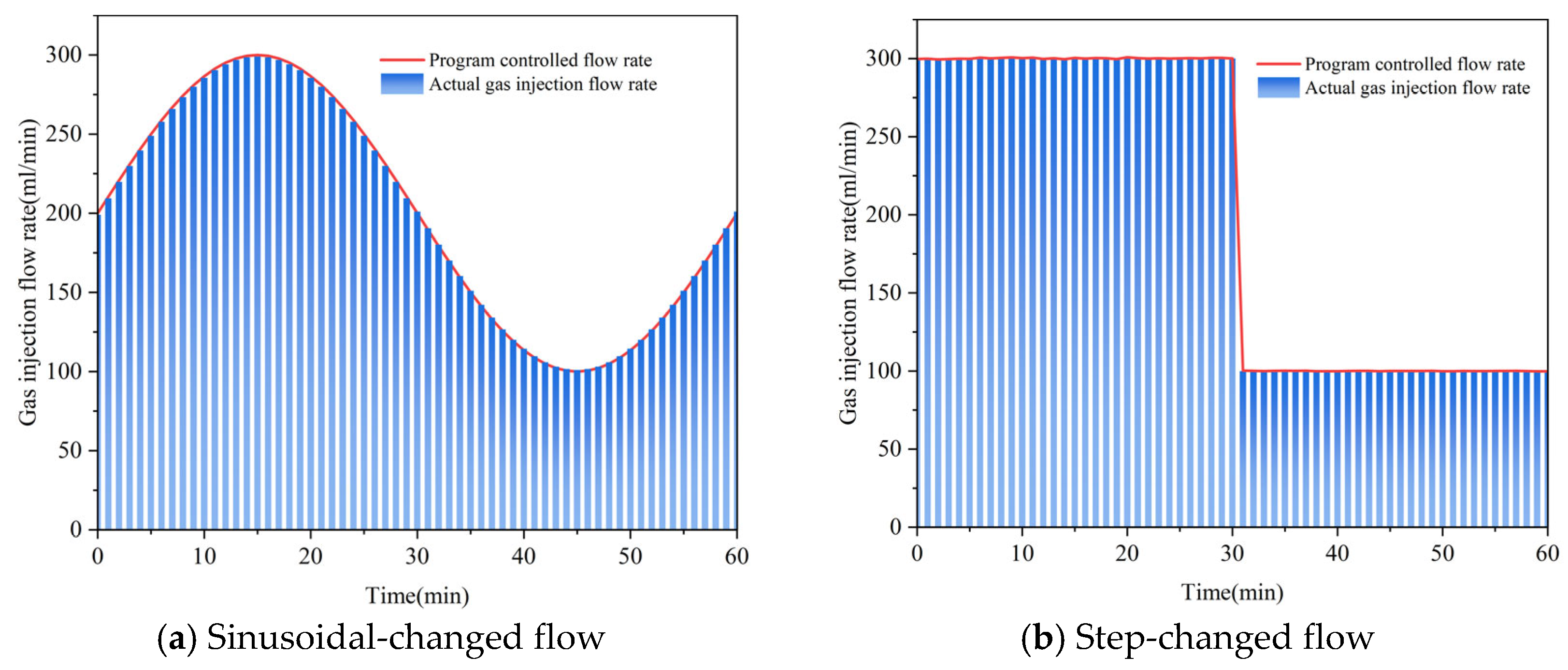
Two cycles of variable-flow injection, sinusoidal-changed and step-changed, were implemented to study their effects on CH4 diffusion behavior. The injection flow rate waveforms for the first cycle are illustrated in Figure 3. The right Y-axis of Figure 3 presents the programmed flowmeter control values for gas injection rate, while the left Y-axis shows the corresponding measured values. In each injection cycle, the injection time of the two injection methods was 3600 s, the injection volume was 12,000 mL, and the injected gas types were selected as N2 and CO2, respectively.
The experimental procedure was conducted as follows:
① Initial System Configuration
Consistent with unidirectional diffusion protocols, the experimental system underwent CH4 pre-adsorption following standard evacuation procedures.
② Gas Injection Phase
The back pressure valve was adjusted to set the gas discharge pressure. Internal gas outflow from the coal sample canister occurs only when the pressure exceeds the back pressure valve setting, which more closely matches actual gas injection displacement engineering scenarios. Simultaneously, N2/CO2 was introduced by opening the inlet valve, with injection rates dynamically controlled via the inlet flowmeter program to maintain predetermined variable flow rates into the coal sample tank.
③ Experimental Data Acquisition
Gas flow sensors were installed at the inlet and outlet ends of the coal sample tank, respectively, to monitor the instantaneous flow rates of injected gas and discharged gas mixture in real time. Simultaneously, a gas concentration detection device at the outlet end monitors the gas composition and volume fractions of the discharged gas. Through the integration of these devices, we achieve real-time and precise monitoring of the composition, volume fractions, and instantaneous flow rates of the outlet gas mixture.
④ Data Acquisition and Termination Criteria
Gas pressure, effluent flow rate, and concentration data were tracked in real-time by the automated acquisition system. Experimental termination was triggered when the CH4 concentration persistently remained below 1% for ≤30 consecutive minutes.
⑤ Experimental Replication
Bidirectional diffusion experiments were concluded by repeating the sequence (Steps ①–④).

3. Experimental Results

3.1. Unidirectional Diffusion Experiments with N2, CO2, CH4

The results of unidirectional diffusion experiments under different adsorption equilibrium pressures are demonstrated in Figure 4. There are two stages. In the initial diffusion stage (0–6 min), equilibrium is disrupted as the pressure gradient decreases. Free gas rapidly flushes out, and small amounts of adsorbed gas desorb. In the second stage (6 min to the end), the gas pressure in the coal samples tank gradually decreases to 0. In this stage, the gas emission is mainly contributed by the desorption of the adsorbed state gas. Furthermore, at identical adsorption equilibrium pressures, the emission amount by unidirectional diffusion followed CO2 > CH4 > N2. This relationship is determined by the coal’s adsorption capacity for each gas. At identical adsorption equilibrium pressures, more gas is adsorbed when the adsorption strength is greater. Consequently, compared to CH4 and N2, more CO2 was ultimately released from the coal. Table 4 presents the unidirectional diffusion experimental results. It is evident that for a given gas, increasing the adsorption equilibrium pressure led to greater gas emission and desorption.

3.2. Bidirectional Diffusion Experiments with Constant Flow Gas Injection

3.2.1. Effect of Pre-Adsorbed Gas Equilibrium Pressure on CH4 Diffusion During Constant Flow Injection

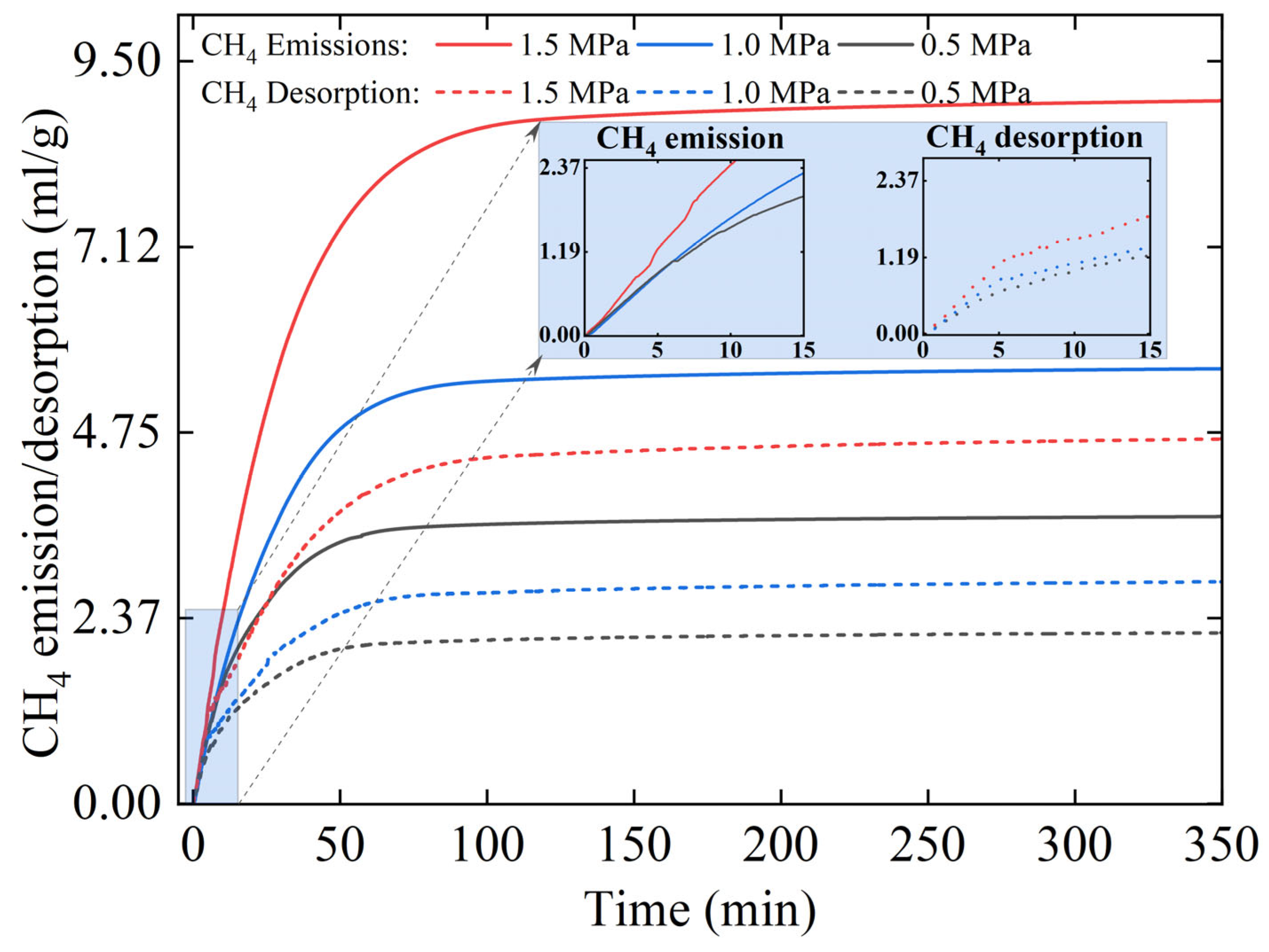
Using constant flow N2 injection for CH4 replacement as an example, Figure 5 demonstrates the trend of CH4 emission and desorption with time under different adsorption equilibrium pressure conditions. At adsorption equilibrium pressures of 0.5 MPa, 1.0 MPa, and 1.5 MPa, the cumulative CH4 emissions were 3.56 mL/g, 5.61 mL/g, and 9.06 mL/g, respectively, and the cumulative CH4 desorption was 2.20 mL/g, 2.87 mL/g, and 4.98 mL/g, respectively. It is evident that higher adsorption equilibrium pressures lead to increased CH4 emissions and desorption over the same time period. In comparison to unidirectional CH4 diffusion, bidirectional diffusion processes resulted in a respective increase of 45.96%, 18.53%, and 21.71% in CH4 emissions at each pre-adsorption gas pressure level. Similarly, CH4 desorption exhibited increases of 163.69%, 188.82%, and 161.12% in the same order. The injection of N2 not only enhances the removal of free CH4 but also effectively promotes the desorption of CH4 in the adsorbed state.

3.2.2. Effect of Different Injection Gas Types on the Diffusion of CH4

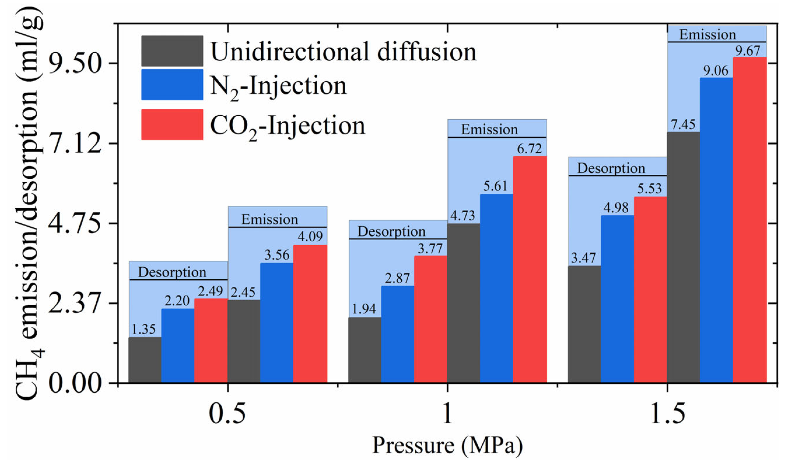
Figure 6 demonstrates the trend of CH4 emission with time for N2/CO2 injection under different adsorption equilibrium pressure conditions. It can be found that the CH4 diffusion pattern is the same when CO2 is injected at constant flow and N2 is injected at constant flow, but the cumulative CH4 emission and desorption are significantly different. In order to further reflect the differences in the bi-directional diffusion patterns of the different gas injection types to drive CH4, we compared the final CH4 emissions and desorption, as shown in Figure 7. Under varying adsorption equilibrium pressures, the cumulative emissions of CH4 during CO2 injection were as follows: 4.09 mL/g (0.5 MPa), 6.72 mL/g (1.0 MPa), and 9.67 mL/g (1.5 MPa), with corresponding desorption volumes of 2.49 mL/g (0.5 MPa), 3.77 mL/g (1.0 MPa), and 5.53 mL/g (1.5 MPa). At the same adsorption equilibrium pressure, the emissions of CH4 replacement by CO2 injection were 1.15, 1.20, and 1.07 times higher than those of N2 injection, while the desorption volumes were 1.13, 1.31, and 1.11 times higher than those of N2 injection. Hence, when subjected to identical injection pressure and injection time, the introduction of CO2 into the coal seam results in a greater displacement of CH4. Figure 7 also illustrates a comparison of CH4 diffusion results between unidirectional and bidirectional diffusion. It can be found that whether N2 or CO2 is injected into the coal body, the cumulative CH4 emission and desorption are significantly higher than the results of unidirectional diffusion of CH4, which indicates that the gas injection replacement has a good effect of “pro-emission” of CH4.

3.3. CH4 Diffusion Experiments for Variable-Flow Gas Injection

3.3.1. Effect of Gas Injection Types and Injection Modes on CH4 Diffusion

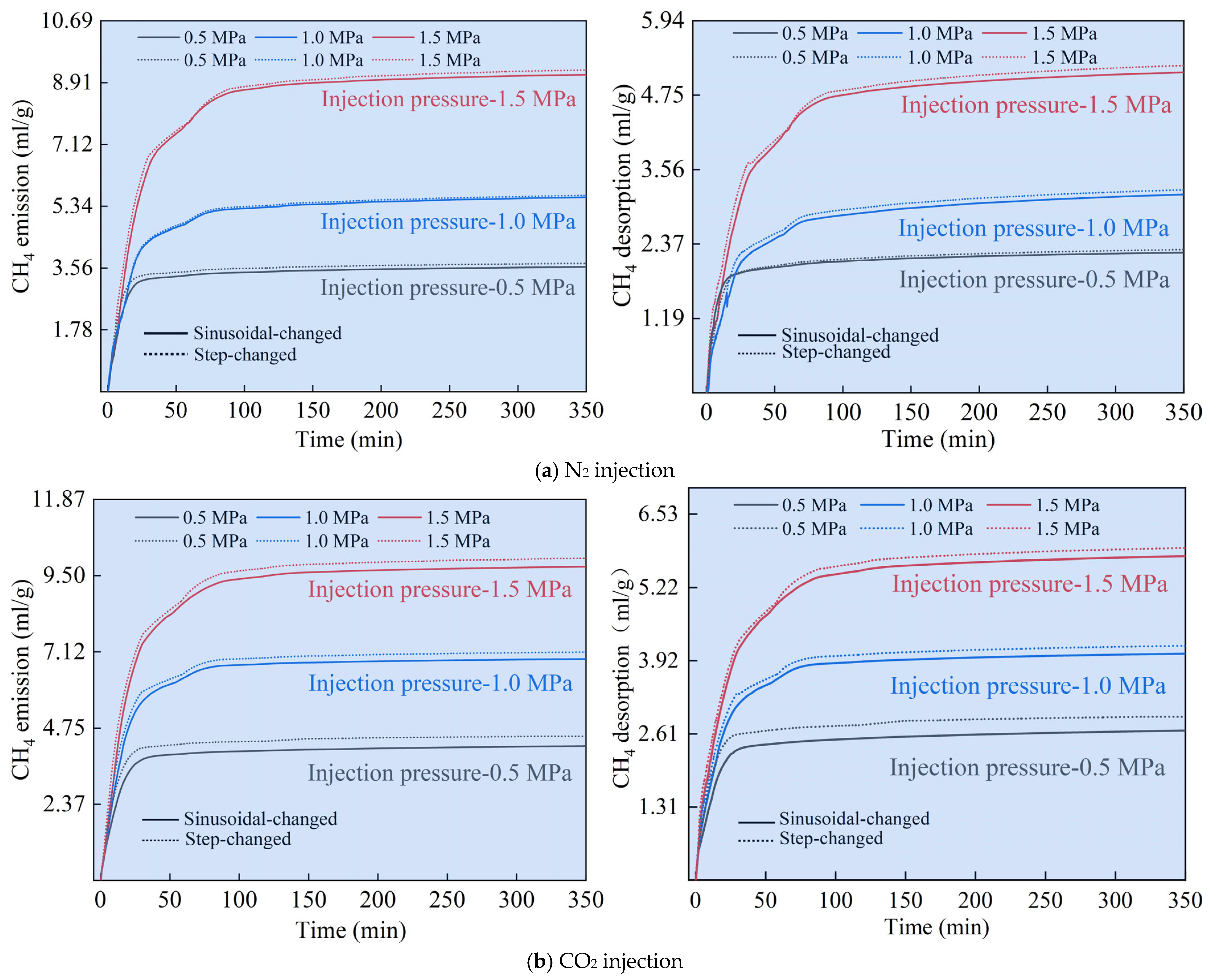
Figure 8 illustrates the effect of various injection gases and injection modes on the bidirectional diffusion of CH4 under identical conditions at each adsorption equilibrium pressure. Figure 9 and Figure 10 present comparisons of CH4 emissions and desorption across three gas injection types: sinusoidal-changed, step-changed, and constant flow. It is evident that CH4 emissions and desorption exhibit an initial rapid increase over time, followed by a gradual attainment of equilibrium. This behavior aligns with the pattern observed during constant-flow gas injection to facilitate CH4 diffusion. However, cumulative CH4 emissions and desorption levels vary under different injection conditions.
In the context of the three injection methods, when CO2 is used as the injected gas, both CH4 emission and desorption are greater compared to when N2 is employed. Furthermore, this difference becomes more pronounced as the pressure level increases. This phenomenon primarily arises from coal’s superior adsorption affinity for CO2 over N2. Free CH4 was flushed out during N2 injection, and the desorbed CH4 was mainly contributed by the reduction of CH4 partial pressure after N2 injection, and only a small portion of the desorbed CH4 was due to the competitive adsorption between N2 and CH4. However, after injecting CO2, the dual effects of lowering CH4 partial pressure and competitive adsorption between CO2 and CH4 enabled more CH4 to be desorbed from the coal body compared with N2 injection. Furthermore, at the same gas adsorption equilibrium pressure level for both N2 and CO2 injection, the extent of CH4 emission and desorption followed this sequence: step-changed > sinusoidal-changed > constant flow, with the variable-flow gas injection method further enhancing CH4 emission from coal. When CO2 was employed as the injected gas, CH4 emissions and desorption under the conditions of step-changed flow injection were significantly higher than those of other injection methods at each pressure level. In contrast, when N2 served as the injected gas, the disparities in CH4 emissions and desorption between sinusoidal-changed and step-changed injection were minimal at pressure levels of 0.5 MPa and 1.0 MPa. However, at a pressure level of 1.5 MPa, CH4 emissions and desorption were notably higher in the step-changed injection method as opposed to the sinusoidal-changed injection method.

3.3.2. Analysis of the Effect of CH4 Replacement by the Principle of Equal-Time and Equal-Quantity Gas Injection

After five cycles, the CH4 emissions and desorption, following all three gas injection methods, exceeded 90%, while the CH4 concentration dropped below 1%. Furthermore, as each group exhibited consistent experimental phenomena, we selected the experimental data from the initial five injection cycles, where the pre-adsorbed gas equilibrium pressure was maintained at 1.5 MPa, for analyzing the displacement effect.
The emissions of CH4 can be divided into two components: the original free CH4 flushed out and the adsorbed CH4 desorbed. As illustrated in Figure 11, irrespective of whether N2 or CO2 is injected, and across the three injection modes, the CH4 emissions during the five injection cycles follow this order: step-changed > sinusoidal-changed > constant flow. Similarly, the CH4 desorption was ranked as follows: step-changed > sinusoidal-changed > constant flow. CH4 emissions can be categorized into three stages. In Stage I, during the first cycle, CH4 emissions significantly exceed those in subsequent cycles. Early in the cycle, a substantial portion of free-state CH4 is flushed out, while in the later part, CH4 adsorbed within the coal matrix pores desorbs, leading to an increasing desorption percentage. In Stage 2, in the second cycle, the decline in CH4 emissions slows down, further reducing initial free-state CH4, with a rapid increase in CH4 desorption at this point. Stage 3 encompasses the third, fourth, and fifth cycles, where the decrease in CH4 emissions levels off. By the fifth cycle, the ratio of CH4 desorption to CH4 emissions reaches approximately 90%. As indicated by Figure 11a, the ratio of N2/CO2 injection to CH4 emission in each cycle exhibits significant divergence after the second cycle. The consumption order of injected gas for each volume of CH4 emitted is as follows: constant flow > sinusoidal-changed > step-changed. This suggests that the variable-flow injection method offers a higher utilization rate of the injected gas and a more effective replacement effect. Notably, under each gas injection method, except for the first cycle, the quantity of injected CO2 surpasses that of injected N2 for the same volume of discharged CH4. This phenomenon results from gradual coal particle adsorption of CO2 over time, leading to an increase in the consumed CO2 volume.
Figure 11b illustrates the order of CH4 desorption as a percentage of CH4 emission in each cycle under various gas injection methods, ranked from highest to lowest as follows: step-changed > sinusoidal-changed > constant flow. When N2 is used as the injected gas, the percentage of CH4 desorption exhibits a rapid increase from the first to the third cycle, reaching 87.69% (step-changed) and 80.86% (sinusoidal-changed) in the third cycle. Subsequently, it gradually rises from the fourth to the fifth cycle, peaking at 95.15% (step-changed) and 93.50% (sinusoidal-changed). Conversely, under constant flow conditions, the proportion of CH4 desorption initially increases slowly from the first to the second cycle, experiences a rapid rise in the third to fourth cycle, yet consistently remains lower than that observed for step and sinusoidal variable flow, culminating at 91.47% in the fifth cycle. When CO2 is utilized as the gas source, the trend of CH4 desorption is consistent with that observed with N2, with the notable difference being a halt in the rapid growth trend of CH4 desorption in the fourth cycle, reaching percentages of 94.45% (step-changed) and 94.21% (sinusoidal-changed). Ultimately, the final CH4 desorption percentages for all three gas injection methods stand at 97.74% (step-changed), 94.97% (sinusoidal-changed), and 93.49% (constant flow) when compared to N2 injection. It is noteworthy that the differences in CH4 desorption between gas injection methods, whether using N2 or CO2, decrease as the duration of gas injection progresses.

4. Analysis of the Applicability of the Gas Diffusion Model in Coal

4.1. Model of Gas Diffusion in Coal Particles

The model of coal particle gas diffusion serves as the foundation for investigating the laws of coal particle gas diffusion. Currently, the established model of coal particle gas diffusion primarily relies on Fick’s diffusion law. The conventional diffusion model categorizes the pores in coal as having unipore, bidisperse, or triple-pore structures. In this study, we selected the commonly employed unipore and bidisperse models for fitting experimental data, aiming to assess the suitability of the diffusion model for CH4 diffusion during gas injection in bidirectional diffusion processes.

4.1.1. Unipore Diffusion Model

The unipore model assumes that coal particles are spherical particles with an isotropic radius, r, and that the gas concentration surrounding these spherical coal particles remains constant. The derivation process is outlined in the existing literature [43], and the expression for the mass fraction of adsorbed/desorbed gas is as follows:
m t m = 1 6 π 2 n = 1 1 n 2 exp n 2 π 2 t D r 2
where mt is the total amount of gas adsorption/desorption at time t (g); m is the total amount of gas adsorption/desorption after reaching equilibrium (g); r is the radius of spherical coal particles (m); D is the diffusion coefficient (m2/s); t is desorption/adsorption time (s); and the value of D/r2 can be considered as the effective diffusion coefficient, De (1/s). In 1975, Crank [55] et al. provided calculations for a unipore model applicable to external concentration variations, considering the limitations of the assumptions of the unipore model. Coal possesses a non-uniform pore structure, and this inherent characteristic presents challenges in applying a single pore diffusion model; however, certain experiments [56,57,58] have demonstrated the applicability of this model in achieving a superior fit with diffusion data.

4.1.2. Bidisperse Diffusion Model

In contrast to the unipore model, which assumes the existence of a single pore type within the coal matrix, the bidisperse model postulates the presence of two distinct pore structures within the coal matrix: macropores and micropores, providing a more comprehensive depiction of gas diffusion within coal. This bidisperse model has found extensive application in predicting CBM production, resource assessment, etc. The model segregates the gas diffusion process within coal into two categories: macropore diffusion, characterized by high speed, and micropore diffusion, characterized by low speed.
For the macropore diffusion stage, the diffusion model can be expressed as follows:
m a m a = 1 6 π 2 n = 1 1 n 2 exp n 2 π 2 t D a r a 2
For the micropore diffusion stage, the diffusion model is then expressed as follows:
m i m i = 1 6 π 2 n = 1 1 n 2 exp n 2 π 2 t D i r i 2
In the above Equations (3) and (4), a and i denote the diffusion parameters corresponding to macropores and micropores, respectively; Da/ra2 and Di/ri2 can be written as the effective diffusion coefficients Dae and Die (1/s), respectively.
Then the total overall adsorption/desorption of coal particles is the sum of the above two stages, which can be expressed by Equation (5):
m t m = m a + m i m a + m i = β m a m a + 1 β m i m i
where β = m a m a + m i is the percentage of gas adsorbed/desorbed by the macropores to the total pore adsorption/desorption.

4.2. Diffusion Model Applicability Analysis

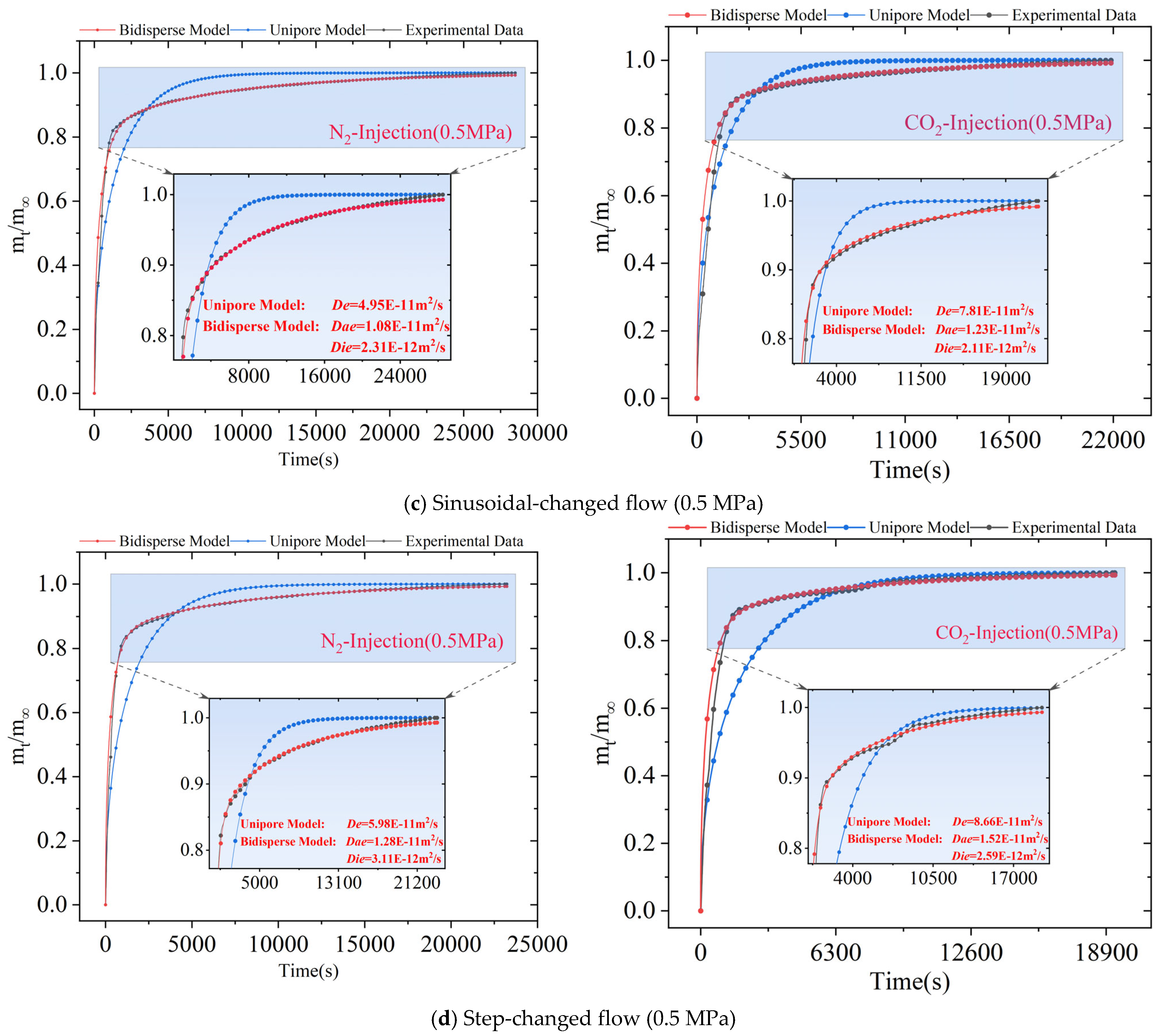
In this paper, the De in the unipore model and the parameters Dae, Die, and β in the bidisperse model were individually adjusted to fit the diffusion behavior of CH4 within the coal during experimentation. The value of n in Equations (2)–(4) was set to 5 in order to obtain the optimal fit for the diffusion parameters based on the experimental mt/m curves and, thus, to carry out the analysis of the suitability of diffusion models. The optimal fitting parameters for each condition can be found in Table 5.
The applicability of unipore and bidisperse models for both unidirectional and bidirectional gas diffusion is separately analyzed. At each pre-adsorption pressure level, these two diffusion models exhibit a high degree of similarity in their respective simulation outcomes, whether for unidirectional or bidirectional diffusion. Therefore, this section presents a comparison between the simulated and experimental diffusion model curves at a pressure level of 0.5 MPa, as depicted in Figure 12. It is evident that, concerning the experimentally measured mt/m curves, the simulated curves of the bidisperse model closely align with the measured curves, outperforming the unipore model. This superiority arises from the fact that, in contrast to the simplified pore structure assumption in the unipore model, the bidisperse model accounts for both macropores and micropores, offering a more accurate representation of the complex pore structure in the coal samples. Additionally, its corresponding diffusion coefficients for macropore and micropore pores provide a more comprehensive explanation of gas diffusion processes within the coal. Furthermore, the bidisperse model demonstrates a significantly enhanced simulation performance for CH4 and CO2 compared to N2 in both unidirectional and bidirectional diffusion scenarios. This is due to the utilization of the bidisperse model, which considers gas adsorption within the coal body, enabling a more precise simulation of the transport behavior of easily adsorbed gases, such as CO2 and CH4, in the coal seam.

4.3. Effect of Different Gas Injection Methods on Diffusion Coefficients

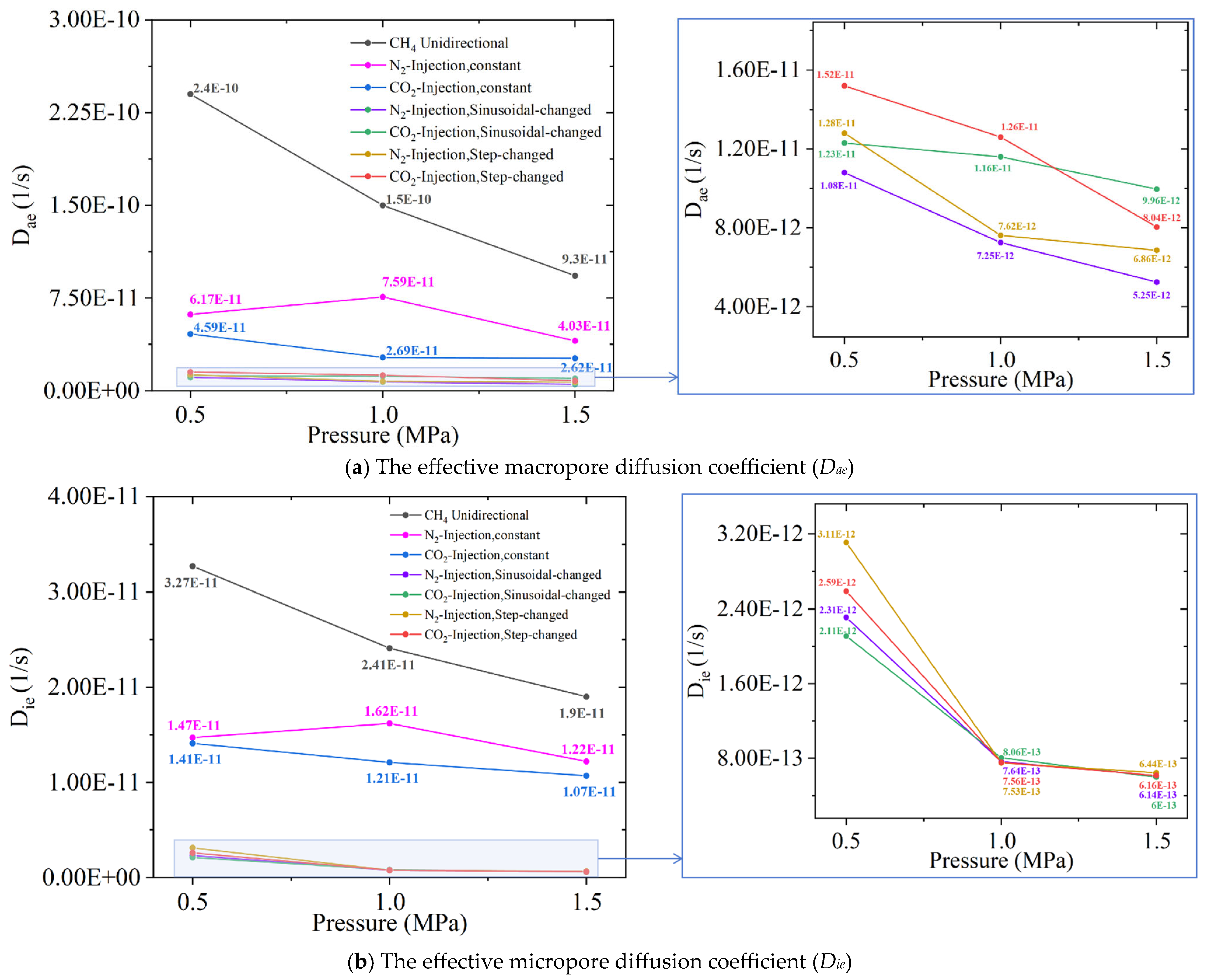
It is well-established that the bidisperse model can better describe the CH4 diffusion-desorption ratio in each experimental process. In this section, we carried out the analysis of the trend of Dae, the effective macropore diffusion coefficient, and Die, the effective micropore diffusion coefficient, under varying pressure conditions for each method of gas injection, as shown in Figure 13. At three different pressure levels, when maintaining a constant flow displacement, the effective diffusion coefficients (Dae and Die) of CH4 exhibited a trend of initially increasing and subsequently decreasing as the injected gas source was N2. Conversely, when CO2 served as the injected gas source, the effective diffusion coefficients (Dae and Die) of CH4 demonstrated a consistent tendency to decrease with increasing pressure. When comparing the Dae and Die values of CH4 diffusion during N2 and CO2 injection, it is evident that the Dae and Die values are greater in the case of N2 injection compared to CO2. In the context of the variable-flow injection method, it is observed that the diffusion coefficients (Dae and Die) of CH4 exhibit a negative correlation with gas pressure when both N2 and CO2 gases are injected. Unlike the constant flow gas injection method, the effective macropore diffusion coefficient (Dae) of CH4 during CO2 injection notably exceeded that observed during N2 injection. Additionally, the effective micropore diffusion coefficient (Die) exhibited a similar trend, surpassing that seen in N2 injection scenarios when CO2 was employed as the injected gas source at a pressure level of 0.5 MPa. Notably, Die remained nearly identical for CH4 in both injection methods, i.e., at 1.0 and 1.5 MPa, underlining its consistent behavior.
Moreover, the unidirectional effective diffusion coefficients, Dae and Die, for CH4 were greater than those for bidirectional diffusion under the same pressure conditions. This suggests that the adsorption of injected N2/CO2 into coal particles reduces the desorption rate of pre-adsorbed CH4 from coal particles, but Section 3 provides evidence supporting the conclusion that the “pro-emission” effect of gas injection and displacement can eliminate the influence of this inhibitory effect.

4.4. Limitations of Unipore and Bidisperse Diffusion Models

Section 4.3 reveals that although the bidisperse diffusion model provides a better fit for CH4 bidirectional diffusion under gas injection than the unipore diffusion model, its predictions still deviate substantially from experimental CH4 diffusion data during displacement. Specifically, at the initial phase, the unipore diffusion yields lower values than experimental measurements, whereas the bidisperse diffusion model produces higher values; at a later phase, the unipore diffusion model yields higher values, while the bidisperse diffusion model generates lower values relative to experimental data.
This paradox indicates that conventional unipore and bidisperse diffusion models inadequately describe CH4 diffusion during gas injection displacement, primarily due to the following:
① Inherent limitation: Both models assume single-gas diffusion, thus failing to capture multi-component interactions during displacement.
② Homogeneity fallacy: Idealized assumptions of uniform coal/porosity [43] contradict natural heterogeneity.
③ Non-Fickian anomalies: Prior studies demonstrate that gas adsorption-induced coal swelling triggers matrix deformation, resulting in non-Fickian anomalous diffusion behavior [59,60,61], which existing single-/dual-pore models fundamentally fail to account for.
④ Dynamic diffusion coefficients: During gas injection displacement, the progressive intrusion of foreign gases into deep-seated pores within the coal matrix causes increasingly complex CH4 diffusion pathways. This results in continuously variable diffusion coefficients of CH4, which cannot be represented by one or several constant values—a phenomenon preliminarily interpreted in Section 4.3.
Consequently, novel diffusion models must be developed to characterize gas bidirectional behavior in displacement scenarios.

5. Discussion

Laboratory experiments have proved that compared with unidirectional diffusion and constant-flow gas injection for CH4 replacement, variable-flow gas injection can enhance CH4 emission and desorption and has a better effect of “pro-emission” of CH4, which is a revelation for the application of variable-flow gas injection in the field of underground gas injection and replacement in coal mines:
(1) It can be inferred from Section 3.3.1 that, when employing variable-flow N2 injection for replacement, and with adsorption equilibrium pressures at 0.5 MPa and 1.0 MPa, there is a small disparity in CH4 emission and desorption between the step-changed flow and sinusoidal-changed flow injection methods. The distinction in CH4 emissions between the two injection methods begins to manifest when the adsorption equilibrium pressure reaches 1.5 MPa. Conversely, under CO2 injection conditions, CH4 emission and desorption in the step-changed injection method exceed those in the sinusoidal-changed flow injection method across all pressure levels. These findings suggest that the step-changed flow N2 injection technology is suited for coal seams characterized by high initial gas pressures or when high-pressure injection (≥1.5 MPa) is employed.
(2) Combined changes in CH4 emissions, desorption, and desorption ratios in Section 3.3.2 reveal that, in scenarios with limited gas sources, step-changed flow and sinusoidal-changed flow gas injection methods can effectively discharge more CH4 and enhance the desorption of adsorbed CH4. Furthermore, when CO2 is chosen as the gas source, these methods outperform their counterparts using N2 as the gas source. However, in situations where the gas source is abundant or substantial, the advantages associated with variable-flow gas injection tend to diminish. Consequently, to fully harness the potential of variable-flow methods for pro-emission, reasonable consideration of the gas injection type and duration is imperative. Moreover, except for the first cycle, where the discharge of the same volume of CH4 is observed, it is noteworthy that the quantity of CO2 injected surpasses that of the injected N2 gas. This phenomenon can be attributed to the gradual adsorption of CO2 by coal particles over time, resulting in an increased consumption of CO2. Furthermore, our findings indicate that employing a CO2 injection for CH4 replacement is more appropriate for enhancing coalbed methane production from surface wells within unrecoverable coal seams while simultaneously sequestering CO2. Conversely, N2 injection for CH4 replacement is deemed suitable for the prevention and control of gas-related disasters in underground recoverable coal seams.
(3) As evidenced by Figure 4, Figure 5, Figure 6 and Figure 13, and Table 5, the diffusion coefficient of CH4 under bidirectional diffusion conditions during gas injection displacement is lower than that observed in unidirectional CH4 diffusion. The injection of foreign gases results in a reduction in the desorption rate of CH4. This phenomenon arises primarily from two mechanisms: (i) Injected gases obstruct diffusion pathways within the coal matrix pores, increasing path tortuosity and thereby reducing the effective diffusion coefficient of CH4. (ii) Gas injection pressure induces pore constriction, heightening diffusion resistance to CH4. However, under sustained operation, while the CH4 desorption rate decreases transiently during displacement (Figure 4, Figure 5 and Figure 6), maintaining system pressure over a sufficient duration enables competitive displacement of deeply adsorbed CH4. This ultimately enhances cumulative CH4 desorption significantly (Figure 7).

6. Conclusions

Laboratory experiments were conducted to investigate CH4 diffusion patterns under two distinct gas injection modes: constant-flow and variable-flow displacement scenarios. Comparative analysis was performed between unidirectional and bidirectional diffusion processes to characterize CH4 diffusion behavior. Under controlled experimental conditions, maintaining equivalent gas injection duration and volume, displacement efficiencies were quantitatively evaluated across both injection modes. Experimental data were subsequently applied to validate the CH4 diffusion model’s accuracy under variable-flow conditions in coal matrices. The conclusions are as follows:
(1) Bidirectional diffusion enhanced by gas injection displacement demonstrates superior CH4 liberation efficiency over unidirectional diffusion at equivalent pressure levels. The injected N2/CO2 gas can promote the adsorption and desorption of CH4 in coal, and the larger the pre-adsorption equilibrium pressure, the larger the emission and desorption of CH4. CO2 exhibits superior displacement efficacy compared to N2, achieving enhanced CH4 recovery through the synergistic action of partial pressure reduction and competitive adsorption mechanisms.
(2) Under identical gas injection parameters (type and pressure), variable-flow displacement achieves superior CH4 liberation compared to constant-flow operation, with ranking as step-variable > sinusoidal-variable > constant-flow regimes. When the gas injection source is CO2, the CH4 emission and desorption at the outlet are larger than that of N2, and the higher the pressure level, the more obvious the difference.
(3) Analysis of equal time and quantity principles reveals the following CH4 desorption-emission order under identical pressure and injection types: stepped-change > sinusoidal-variation > constant flow. However, cyclic progression shows three key trends: the CH4 emission decline rate decreases, the desorption ratio accelerates, and the inter-method desorption differences diminish. From the second cycle onward, gas injection-to-CH4 emission ratios demonstrate consumption efficiency as: constant flow > sinusoidal-variation > stepped-change, confirming variable-flow methods’ superior displacement effects. Additionally, CO2 consistently exhibits higher consumption per CH4 emission volume than N2 across all cycles except the first.
(4) The bidisperse diffusion model demonstrates superior fitting accuracy to the unipore model for CH4 desorption ratios under both constant-flow and variable-flow displacement. For bidirectional diffusion of constant flow displacement, the effective diffusion coefficients Dae and Die of CH4 first increase and then decrease with the increase in pressure when N2 is injected, while the effective diffusion coefficients Dae and Die of CH4 decrease with the increase in pressure when CO2 is injected. For bidirectional diffusion with variable-flow, whether N2 or CO2 is injected, the Dae and Die of CH4 are negatively correlated with the gas pressure. Notably, CO2 injection produces significantly higher macropore Dae values than N2 across pressure levels. For micropore Die at 0.5 MPa, CO2 injection yields greater CH4 diffusion coefficients compared to N2, while values converge at 1.0 and 1.5 MPa pressures.

Author Contributions

J.W.: Methodology, Investigation, Writing—original draft. H.G.: Formal analysis, Writing—review and editing. G.Z.: Investigation, Writing—review and editing. Z.L.: Investigation, Formal analysis. J.H.: Investigation, Methodology. All authors have read and agreed to the published version of the manuscript.

Funding

This research was funded by the National Natural Science Foundation of China (51604153) and the Henan Province Science and Technology Research Projects (232102320233, 252102220013).

Data Availability Statement

The original contributions presented in this study are included in the article. Further inquiries can be directed to the corresponding author.

Conflicts of Interest

The authors declare no conflict of interest.

References

  1. Reeves, S.; Taillefert, A.; Pekot, L.; Clarkson, C. The Allison Unit CO2-ECBM Pilot: A Reservoir Modeling Study; Topical Report DE-FC26-0NT4092433; U.S. Department of Energy: Washington, DC, USA, 2003. [CrossRef]
  2. Fujioka, M.; Yamaguchi, S.; Nako, M. CO2-ECBM field tests in the Ishikari coal basin of Japan. Int. J. Coal Geol. 2010, 82, 287–298. [Google Scholar] [CrossRef]
  3. Wong, S.; Law, D.; Deng, X.; Robinson, J.; Kadatz, B.; Gunter, W.D.; Ye, J.; Feng, S.; Fan, Z. Enhanced coalbed methane and CO2 storage in anthracitic coals—Micro-pilot test at South Qinshui, Shanxi, China. Int. J. Greenh. Gas Control 2007, 1, 215–222. [Google Scholar] [CrossRef]
  4. van Bergen, F.; Krzystolik, P.; van Wageningen, N.; Pagnier, H.; Jura, B.; Skiba, J.; Winthaegen, P.; Kobiela, Z. Production of gas from coal seams in the Upper Silesian Coal Basin in Poland in the post-injection period of an ECBM pilot site. Int. J. Coal Geol. 2008, 77, 175–187. [Google Scholar] [CrossRef]
  5. Gong, H.; Wang, K.; Wang, G.; Yang, X.; Du, F. Underground coal seam gas displacement by injecting nitrogen: Field test and effect prediction. Fuel 2021, 306, 121646. [Google Scholar] [CrossRef]
  6. Yang, X.; Wang, G.; Du, F.; Jin, L.; Gong, H. N2 injection to enhance coal seam gas drainage (N2-ECGD): Insights from underground field trial investigation. Energy 2022, 239, 122247. [Google Scholar] [CrossRef]
  7. Lin, J.; Ren, T.; Cheng, Y.; Nemcik, J.; Wang, G. Cyclic N2 injection for enhanced coal seam gas recovery: A laboratory study. Energy 2019, 188, 116115. [Google Scholar] [CrossRef]
  8. Packham, R.; Connell, L.; Cinar, Y.; Moreby, R. Observations from an enhanced gas recovery field trial for coal mine gas management. Int. J. Coal Geol. 2012, 100, 82–92. [Google Scholar] [CrossRef]
  9. Reeves, S.R. The Coal-Seq project: Key results from field, laboratory, and modeling studies. In Proceedings of the 7th International Conference on Greenhouse Gas Control Technologies, Vancouver, BC, Canada, 5–9 September 2004. [Google Scholar] [CrossRef]
  10. Bustin, A.M.M.; Bustin, R.; Chikatamarla, L.; Downey, R.; Mansoori, J. Learnings from a failed nitrogen enhanced coalbed methane pilot: Piceance Basin, Colorado. Int. J. Coal Geol. 2016, 165, 64–75. [Google Scholar] [CrossRef]
  11. Mazzotti, M.; Pini, R.; Storti, G. Enhanced coalbed methane recovery. J. Supercrit. Fluids 2008, 47, 619–627. [Google Scholar] [CrossRef]
  12. Pan, Z.; Connell, L.D. Comparison of adsorption models in reservoir simulation of enhanced coalbed methane recovery and CO2 sequestration in coal. Int. J. Greenh. Gas Control 2008, 3, 77–89. [Google Scholar] [CrossRef]
  13. Shi, J.-Q.; Durucan, S.; Fujioka, M. A reservoir simulation study of CO2 injection and N2 flooding at the Ishikari coalfield CO2 storage pilot project, Japan. Int. J. Greenh. Gas Control 2008, 2, 47–57. [Google Scholar] [CrossRef]
  14. Gunter, W.D.; Mavor, M.J.; Robinson, J.R. CO2 storage and enhanced methane production: Field testing at the Fenn-Big Valley, Alberta, Canada, with application. In Proceedings of the 7th International Conferenceon Greenhouse Gas Control Technologies, Vancouver, BC, Canada, 5–9 September 2004. [Google Scholar]
  15. Durucan, S.; Shi, J.-Q. Improving the CO2 well injectivity and enhanced coalbed methane production performance in coal seams. Int. J. Coal Geol. 2008, 77, 214–221. [Google Scholar] [CrossRef]
  16. Battistutta, E.; Van Hemert, P.; Lutynski, M.; Bruining, H.; Wolf, K.H. Swelling and sorption experiments on methane, nitrogen and carbon dioxide on dry Selar Cornish coal. Int. J. Coal Geol. 2010, 84, 39–48. [Google Scholar] [CrossRef]
  17. Fitzgerald, J.E.; Pan, Z.; Sudibandriyo, M.; Robinson, R.L., Jr.; Gasem, K.A.M.; Reeves, S. Adsorption of methane, nitrogen, carbon dioxide and their mixtures on wet Tiffany coal. Fuel 2005, 84, 2351–2363. [Google Scholar] [CrossRef]
  18. Cui, X.; Bustin, R.M.; Dipple, G. Selective transport of CO2, CH4, and N2 in coals: Insights from modeling of experimental gas adsorption data. Fuel 2004, 83, 293–303. [Google Scholar] [CrossRef]
  19. Tang, X. Surface thermodynamics of hydrocarbon vapors and carbon dioxide adsorption on shales. Fuel 2019, 238, 402–411. [Google Scholar] [CrossRef]
  20. Lin, J.; Ren, T.; Wang, G.; Booth, P.; Nemcik, J. Experimental investigation of N2 injection to enhance gas drainage in CO2-rich low permeable seam. Fuel 2018, 215, 665–674. [Google Scholar] [CrossRef]
  21. Zhang, L.; Li, J.; Xue, J.; Zhang, C.; Fang, X. Experimental studies on the changing characteristics of the gas flow capacity on bituminous coal in CO2-ECBM and N2-ECBM. Fuel 2021, 291, 120115. [Google Scholar] [CrossRef]
  22. Akbarzadeh, H.; Abbaspour, M.; Salemi, S.; Akbari, M. Injection of mixture of shale gases in a nanoscale pore of graphite and their displacement by CO2/N2 gases using molecular dynamics study. J. Mol. Liq. 2017, 248, 439–446. [Google Scholar] [CrossRef]
  23. Wang, L.; Wang, Z.; Li, K.; Chen, H. Comparison of enhanced coalbed methane recovery by pure N2 and CO2 injection: Experimental observations and numerical simulation. J. Nat. Gas Sci. Eng. 2015, 23, 363–372. [Google Scholar] [CrossRef]
  24. Ji, P.; Lin, H.; Kong, X.; Li, S.; Cai, Y.; Wang, R.; Tian, Y.; Zhao, T.-S. Experimental study on enhanced coal seam gas extraction by uniform pressure/pulse pressure N2 injection. Fuel 2023, 351, 128988. [Google Scholar] [CrossRef]
  25. Yin, G.; Deng, B.; Li, M.; Zhang, D.; Wang, W.; Li, W.; Li, W.; Shang, D. Impact of injection pressure on CO2–enhanced coalbed methane recovery considering mass transfer between coal fracture and matrix. Fuel 2017, 196, 288–297. [Google Scholar] [CrossRef]
  26. Kumar, H.; Elsworth, D.; Mathews, J.P.; Liu, J.; Pone, D. Effect of CO2 injection on heterogeneously permeable coalbed reservoirs. Fuel 2014, 135, 509–521. [Google Scholar] [CrossRef]
  27. Fan, Z.; Fan, G.; Zhang, D.; Zhang, L.; Zhang, S.; Liang, S.; Yu, W. Optimal injection timing and gas mixture proportion for enhancing coalbed methane recovery. Energy 2021, 222, 119880. [Google Scholar] [CrossRef]
  28. Ranathunga, A.S.; Perera, M.S.A.; Ranjith, P.G.; Wei, C.H. An experimental investigation of applicability of CO2 enhanced coal bed methane recovery to low rank coal. Fuel 2017, 189, 391–399. [Google Scholar] [CrossRef]
  29. Vishal, V.; Singh, T.N.; Ranjith, P.G. Influence of sorption time in CO2-ECBM process in Indian coals using coupled numerical simulation. Fuel 2015, 139, 51–58. [Google Scholar] [CrossRef]
  30. Sander, R.; Connell, L.D.; Pan, Z.; Camilleri, M.; Heryanto, D.; Lupton, N. Core flooding experiments of CO2 enhanced coalbed methane recovery. Int. J. Coal Geol. 2014, 131, 113–125. [Google Scholar] [CrossRef]
  31. Connell, L.D.; Sander, R.; Pan, Z.; Camilleri, M.; Heryanto, D. History matching of enhanced coal bed methane laboratory core flood tests. Int. J. Coal Geol. 2011, 87, 128–138. [Google Scholar] [CrossRef]
  32. Deisman, N.; Khajeh, M.; Chalaturnyk, R.J. Using geological strength index (GSI) to model uncertainty in rock mass properties of coal for CBM/ECBM reservoir geomechanics. Int. J. Coal Geol. 2013, 112, 76–86. [Google Scholar] [CrossRef]
  33. Liu, Z.; Cheng, Y.; Wang, Y.; Wang, L.; Li, W. Experimental investigation of CO2 injection into coal seam reservoir at in-situ stress conditions for enhanced coalbed methane recovery. Fuel 2019, 236, 709–716. [Google Scholar] [CrossRef]
  34. Sun, J.; Chen, C.; Zhang, Y.; Li, W.; Song, Y. Competitive adsorption characteristics based on partial pressure and adsorption mechanism of CO2/CH4 mixture in shale pores. Chem. Eng. J. 2022, 430, 133172. [Google Scholar] [CrossRef]
  35. Zhou, G.; Duan, X.; Chang, J.; Bo, Y.; Huang, Y. Investigation of CH4/CO2 competitive adsorption-desorption mechanisms for enhanced shale gas production and carbon sequestration using nuclear magnetic resonance. Energy 2023, 278, 127964. [Google Scholar] [CrossRef]
  36. Wang, F.; Yao, Y.; Wen, Z.; Sun, Q.; Yuan, X. Effect of water occurrences on methane adsorption capacity of coal: A comparison between bituminous coal and anthracite coal. Fuel 2020, 266, 117102. [Google Scholar] [CrossRef]
  37. Jia, J.; Wang, D.; Li, B.; Wu, Y.; Zhao, D. Molecular simulation study on the effect of coal metamorphism on the competitive adsorption of CO2/CH4 in binary system. Fuel 2023, 335, 127046. [Google Scholar] [CrossRef]
  38. Liu, W.; Chu, X.; Xu, H.; Yang, T.; Qin, Y.; Zhao, W. Migration behavior of two-component gases among CO2, N2 and O2 in coal particles during adsorption. Fuel 2022, 313, 123003. [Google Scholar] [CrossRef]
  39. Wu, S.; Deng, C.; Wang, X. Molecular simulation of flue gas and CH4 competitive adsorption in dry and wet coal. J. Nat. Gas Sci. Eng. 2019, 71, 102980. [Google Scholar] [CrossRef]
  40. Li, Z.; Sun, X.; Zhao, K.; Lei, C.; Wen, H.; Ma, L.; Shu, C.-M. Deformation mechanism and displacement ability during CO2 displacing CH4 in coal seam under different temperatures. J. Nat. Gas Sci. Eng. 2022, 108, 104838. [Google Scholar] [CrossRef]
  41. Rani, S.; Prusty, B.K.; Pal, S.K. Adsorption kinetics and diffusion modeling of CH4 and CO2 in Indian shales. Fuel 2018, 216, 61–70. [Google Scholar] [CrossRef]
  42. Charrière, D.; Pokryszka, Z.; Behra, P. Effect of pressure and temperature on diffusion of CO2 and CH4 into coal from the Lorraine basin (France). Int. J. Coal Geol. 2010, 81, 373–380. [Google Scholar] [CrossRef]
  43. Wang, G.; Ren, T.; Qi, Q.; Lin, J.; Liu, Q.; Zhang, J. Determining the diffusion coefficient of gas diffusion in coal: Development of numerical solution. Fuel 2017, 196, 47–58. [Google Scholar] [CrossRef]
  44. Shi, J.Q.; Durucan, S. A bidisperse pore diffusion model for methane displacement desorption in coal by CO2 injection. Fuel 2003, 82, 1219–1229. [Google Scholar] [CrossRef]
  45. Liu, Q.; Wang, J.; Zhao, W.; Huang, W.; Ling, H.; Wang, L.; Cheng, Y. A novel bidisperse diffusion model for coal particles considering micropores as the major sites of CH4 adsorption. Fuel 2023, 333, 126505. [Google Scholar] [CrossRef]
  46. Staib, G.; Sakurovs, R.; Gray, E.M.A. Dispersive diffusion of gases in coals. Part I: Model development. Fuel 2015, 143, 612–619. [Google Scholar] [CrossRef]
  47. Staib, G.; Sakurovs, R.; Gray, E.M.A. Dispersive diffusion of gases in coals. Part II: An assessment of previously proposed physical mechanisms of diffusion in coal. Fuel 2015, 143, 620–629. [Google Scholar] [CrossRef]
  48. Ajoma, E.; Saira; Sungkachart, T.; Ge, J.; Le-Hussain, F. Water-saturated CO2 injection to improve oil recovery and CO2 storage. Appl. Energy 2020, 266, 114853. [Google Scholar] [CrossRef]
  49. Hao, Y.; Li, Z.; Su, Y.; Kong, C.; Chen, H.; Meng, Y. Experimental investigation of CO2 storage and oil production of different CO2 injection methods at pore-scale and core-scale. Energy 2022, 254, 124349. [Google Scholar] [CrossRef]
  50. Zanganeh, P.; Dashti, H.; Ayatollahi, S. Comparing the effects of CH4, CO2, and N2 injection on asphaltene precipitation and deposition at reservoir condition: A visual and modeling study. Fuel 2018, 217, 633–641. [Google Scholar] [CrossRef]
  51. Mohammadi, K.; Ameli, F. Toward mechanistic understanding of Fast SAGD process in naturally fractured heavy oil reservoirs: Application of response surface methodology and genetic algorithm. Fuel 2019, 253, 840–856. [Google Scholar] [CrossRef]
  52. Li, D.; Saraji, S.; Jiao, Z.; Zhang, Y. CO2 injection strategies for enhanced oil recovery and geological sequestration in a tight reservoir: An experimental study. Fuel 2021, 284, 119013. [Google Scholar] [CrossRef]
  53. Badrouchi, N.; Pu, H.; Smith, S.; Badrouchi, F. Evaluation of CO2 enhanced oil recovery in unconventional reservoirs: Experimental parametric study in the Bakken. Fuel 2022, 312, 122941. [Google Scholar] [CrossRef]
  54. Xue, H.; Gui, X.; Wang, G.; Yang, X.; Gong, H.; Du, F. Prediction of gas drainage changes from nitrogen replacement: A study of a TCN deep learning model with integrated attention mechanism. Fuel 2024, 357, 129797. [Google Scholar] [CrossRef]
  55. Crank, J. The Mathematics of Diffusion; Clarendon Press: Oxford, UK, 1975. [Google Scholar]
  56. Jian, X.; Guan, P.; Zhang, W. Carbon dioxide sorption and diffusion in coals: Experimental investigation and modeling. Sci. China Earth Sci. 2012, 55, 633–643. [Google Scholar] [CrossRef]
  57. Švábová, M.; Weishauptová, Z.; Přibyl, O. The effect of moisture on the sorption process of CO2 on coal. Fuel 2012, 92, 187–196. [Google Scholar] [CrossRef]
  58. Pone, J.D.N.; Halleck, P.M.; Mathews, J.P. Sorption capacity and sorption kinetic measurements of CO2 and CH4 in confined and unconfined bituminous coal. Energy Fuels 2009, 23, 4688–4695. [Google Scholar] [CrossRef]
  59. Mazumder, S.; Wolf, K.H. Differential swelling and permeability change of coal in response to CO2 injection for ECBM. Int. J. Coal Geol. 2008, 74, 123–138. [Google Scholar] [CrossRef]
  60. Clarkson, C.R.; Bustin, R.M. The effect of pore structure and gas pressure upon the transport properties of coal: A laboratory and modeling study. 1. Isotherms and pore volume distributions. Fuel 1999, 78, 1333–1344. [Google Scholar] [CrossRef]
  61. Thomas, N.L.; Windle, A.H. A theory of case II diffusion. Polymer 1982, 23, 529–542. [Google Scholar] [CrossRef]
Figure 1. Raw coal collection location and coal sample preparation.
Processes 13 02642 g001
Figure 2. Schematic diagram of bidirectional diffusion apparatus (1—High-pressure cylinder; 2—Relief valve; 3—Six-way valve; 4, 12—Gas flow-meter; 5, 10, 14, 16—Stop valve; 6, 8—Gas pressure sensor; 7—Coal sample tank; 9—Thermostat box; 11—Back-pressure valve; 13—Gas concentration sensor; 15—Vacuum pump; 17—Data acquisition computer).
Processes 13 02642 g002
Figure 3. Programmed and actual values of variable-flow gas injection profiles across each cycle.
Processes 13 02642 g003
Figure 4. Unidirectional diffusion emissions of N2, CO2, and CH4.
Processes 13 02642 g004
Figure 5. Changes of CH4 emission and desorption during constant flow N2 injection under different pressure conditions.
Processes 13 02642 g005
Figure 6. Changes in CH4 emission under different conditions of N2/CO2 injection.
Processes 13 02642 g006
Figure 7. Comparison of CH4 emission and desorption under different conditions of N2/CO2 injection.
Processes 13 02642 g007
Figure 8. Effect of gas injection type and gas injection method on CH4 diffusion at different pre-adsorption gas equilibrium pressure levels.
Processes 13 02642 g008
Figure 9. Comparison of CH4 emissions.
Processes 13 02642 g009
Figure 10. Comparison of CH4 desorption.
Processes 13 02642 g010
Figure 11. Analysis of the effect of CH4 replacement by the principle of equal-time and equal-volume gas injection.
Processes 13 02642 g011
Figure 12. The applicability of unipore and bidisperse models for both unidirectional and bidirectional gas diffusion.
Processes 13 02642 g012aProcesses 13 02642 g012b
Figure 13. Variation of CH4 effective macropore diffusion coefficient (Dae) and effective micropore diffusion coefficient (Die) with gas pressure for each gas injection method.
Processes 13 02642 g013
Table 1. Basic parameters of coal samples [54].
Coal SampleMoisture (%)Ash (%)Volatile Matter (%)Porosity (%)
Xiao Jiawa 13#2.0931.3929.874.82
Table 2. Experimental parameters for unidirectional diffusion experiments.
NumberAdsorbed GasAdsorption Equilibrium Pressure/MPa
1CH40.5, 1.0, 1.5
2N2
3CO2
Table 3. Experimental parameters for bidirectional diffusion experiments.
NumberInjected GasAdsorbed GasGas Injection MethodGas Injection Flow Rate/(mL/min)Adsorption Equilibrium Pressure/MPaReplacement
Pressure/MPa
1N2CH4Constant y = 2000.5, 1.0, 1.50.5, 1.0, 1.5
Sinusoidal-changed y = 100 sin π 30 t + 200
Step-changed y = 300 ,                 0 + 60 n t 30 + 60 n 100 ,             30 + 60 n t 60 + 60 n ( n = 0 , 1 , 2 , 3 )
2CO2CH4Constant y = 2000.5, 1.0, 1.50.5, 1.0, 1.5
Sinusoidal-changed y = 100 sin π 30 t + 200
Step-changed y = 300 ,                 0 + 60 n t 30 + 60 n 100 ,             30 + 60 n t 60 + 60 n ( n = 0 , 1 , 2 , 3 )
Note: t is the injection time, min; y is the gas injection flow rate at moment t, mL/min.
Table 4. The unidirectional diffusion experimental results.
Gas TypeAdsorption Equilibrium Pressure (MPa)Gas Emission
(mL/g)
Gas Desorption
(mL/g)
CH40.52.451.35
1.04.731.94
1.57.443.47
CO20.52.85/
1.05.79
1.58.84
N20.52.27/
1.04.43
1.56.37
Table 5. The optimal fitting parameters for each condition.
Type of Gas InjectionAdsorption Equilibrium Pressure/(MPa)Unipore ModelBidisperse Model
De/(m2/s) D a e /(m2/s) D i e
CH4 unidirectional diffusion0.58.39 × 10−102.41 × 10−103.27 × 10⁻¹¹
1.07.21 × 10−101.53 × 10−102.41 × 10⁻¹¹
1.58.07 × 10−109.32 × 10−111.94 × 10⁻¹¹
Constant flow injection of N2 to replace CH40.53.78 × 10−106.17 × 10−111.47 × 10⁻¹¹
1.08.21 × 10−107.59 × 10−111.62 × 10⁻¹¹
1.57.06 × 10−104.03 × 10−111.22 × 10⁻¹¹
Constant flow injection of CO2 to replace CH40.51.49 × 10−104.59 × 10−111.41 × 10⁻¹¹
1.01.66 × 10−102.69 × 10−111.21 × 10⁻¹¹
1.50.97 × 10−112.62 × 10−111.07 × 10⁻¹¹
Sinusoidal-changed flow injection of N2 to replace CH40.54.95 × 10−111.08 × 10−112.31 × 10⁻¹²
1.02.23 × 10−117.25 × 10−127.64 × 10⁻¹³
1.51.92 × 10−115.25 × 10−126.14 × 10⁻¹³
Sinusoidal-changed flow injection of CO2 to replace CH40.57.81 × 10−111.23 × 10−112.11 × 10⁻¹²
1.05.19 × 10−111.16 × 10−118.06 × 10⁻¹³
1.53.55 × 10−119.96 × 10−126.00 × 10⁻¹³
Step-changed flow injection of N2 to replace CH4 0.55.98 × 10−111.28 × 10−113.11 × 10⁻¹²
1.02.79 × 10−117.62 × 10−127.53 × 10⁻¹³
1.52.16 × 10−116.86 × 10−126.44 × 10⁻¹³
Step-changed flow injection of CO2 to replace CH4 0.58.66 × 10−111.52 × 10−112.59 × 10⁻¹²
1.05.54 × 10−111.26 × 10−117.56 × 10⁻¹³
1.53.86 × 10−118.02 × 10−126.16 × 10⁻¹³
Disclaimer/Publisher’s Note: The statements, opinions and data contained in all publications are solely those of the individual author(s) and contributor(s) and not of MDPI and/or the editor(s). MDPI and/or the editor(s) disclaim responsibility for any injury to people or property resulting from any ideas, methods, instructions or products referred to in the content.