Abstract
With the rapid development of renewable energy, the proportion of small hydropower as a clean energy in the distribution network (DN) is increasing. However, the randomness and intermittence of small hydropower has brought new challenges to the operation of DN; especially, the problems of increasing network loss and reactive voltage exceeding the limit have become increasingly prominent. Aiming at the above problems, this paper proposes a reactive power optimization control method for DN with hydropower based on an improved discrete particle swarm optimization (PSO) algorithm. Firstly, this paper analyzes the specific characteristics of small hydropower and establishes its mathematical model. Secondly, considering the constraints of bus voltage and generator RP output, an extended minimum objective function for system power loss is established, with bus voltage violation serving as the penalty function. Then, in order to solve the following problems: that the traditional discrete PSO algorithm is easy to fall into local optimization and slow convergence, this paper proposes an improved discrete PSO algorithm, which improves the global search ability and convergence speed by introducing adaptive inertia weight. Finally, based on the IEEE-33 buses distribution system as an example, the simulation analysis shows that compared with GA optimization, the line loss can be reduced by 3.4% in the wet season and 13.6% in the dry season. Therefore, the proposed method can effectively reduce the network loss and improve the voltage quality, which verifies the effectiveness and superiority of the proposed method.
1. Introduction
In recent years, with the global adjustment of energy structures and the heightened awareness of environmental protection, the development and utilization of renewable energy have garnered extensive attention [1]. As a crucial component of clean energy, small hydropower, characterized by abundant resources and mature technology, has seen its integration ratio in DN continually increase. However, the randomness and intermittency of small hydropower have posed new challenges to the operation of DNs, particularly highlighting issues such as increased network losses and reactive voltage violations. The integration of small hydropower into DN alters the power flow distribution within the system, leading to changes in network loss characteristics [2,3]. Meanwhile, the mismatch between the generation characteristics of small hydropower and load demand may cause localized voltage increases or decreases, impacting power quality. These issues not only elevate the operational costs of DN but may also jeopardize the safe and stable operation of the system [4,56]. Therefore, studying the changes in network losses and reactive voltage violations caused by the integration of small hydropower holds significant theoretical and practical importance.
In the power system, power quality, as a core indicator of power supply, directly impacts equipment safety, production efficiency, and grid stability [7]. As one of the indicators of power quality, voltage must be maintained within a qualified range [8,9]. The integration of small hydropower into DN significantly alters the power flow distribution of the system, thereby affecting network losses and reactive voltage characteristics. Research in the literature [10] indicates that the location and capacity of small hydropower integration are key factors influencing network losses in DN. Through simulation analysis, they found that when the integration point of small hydropower is close to the load center, it can effectively reduce network losses; whereas, when the integration point is far from the load center, it may lead to increased network losses. Additionally, fluctuations in the output of small hydropower can also cause random variations in network losses, increasing the difficulty of network loss prediction and control. In terms of reactive voltage, the integration of small hydropower may lead to voltage limit violations. Reference [11] points out that the mismatch between the generation characteristics of small hydropower and load demand is the primary cause of voltage limit violations. During wet seasons, small hydropower may inject a large amount of RP into the grid, causing localized voltage increases; whereas, during dry seasons, the insufficient RP support from small hydropower may result in voltage decreases. Such voltage fluctuations not only affect power quality but may also damage electrical equipment. To quantify the impact of small hydropower integration on DN, researchers have proposed various assessment methods. Reference [12] introduces an assessment method based on probabilistic power flow, which can consider the uncertainty of small hydropower output and accurately assess its impact on network losses and voltage. However, these methods often face high computational complexity when dealing with large-scale DN, making it difficult to meet the requirements of real-time assessment [12,13].
The variation in network losses caused by the integration of small hydropower is a crucial issue in the operation of DN. Reference [14] analyzes the impact mechanism of small hydropower integration on network losses by establishing a detailed DN model. They found that the variation in network losses due to small hydropower integration mainly depends on its integration location, capacity, and output characteristics. Integrating small hydropower with an appropriate capacity near the load center can effectively reduce network losses, while integrating large-capacity small hydropower far from the load center may lead to increased network losses. To accurately assess the variation in network losses caused by small hydropower integration, researchers have proposed various calculation methods. Reference [15] introduces a network loss calculation method based on sensitivity analysis, which can rapidly evaluate the impact of small hydropower integration on network losses. Their research shows that this method significantly improves calculation efficiency while ensuring calculation accuracy. However, these methods still have limitations when dealing with the uncertainty of small hydropower output. To address the issue of random variations in network losses caused by fluctuations in small hydropower output, the literature [16] proposes a network loss evaluation method based on scenario analysis. They use historical data to generate multiple typical scenarios, calculate the network losses for each scenario separately, and then obtain the distribution characteristics of network losses through probabilistic statistical methods. Although this method enhances the reliability of evaluation results, it involves a large amount of calculation and is difficult to apply for real-time analysis.
The RP and voltage issues caused by the integration of small hydropower represent another significant challenge in the operation of DN [17,18]. Reference [19] points out that traditional RP and voltage control methods often yield poor results when dealing with DNs containing small hydropower. They propose a voltage regulation method based on distributed control, which effectively improves voltage quality by coordinating the operation of small hydropower, capacitors, transformers, and other equipment. However, this method strongly relies on the communication system and may face reliability issues in practical applications. To address the challenges posed by the uncertainty of small hydropower output, reference [20] introduces an RP and voltage control strategy based on model-predictive control. This method utilizes short-term forecasting information of small hydropower output to optimize the operating status of control equipment, ensuring voltage quality while reducing control costs. Their research shows that this method performs well in dealing with fluctuations in small hydropower output but may affect control effectiveness when prediction accuracy is insufficient. In recent years, with the development of artificial intelligence technology, some scholars have begun to explore the use of machine learning methods for RP and voltage control. Reference [21] proposes a voltage control method based on deep reinforcement learning, which can adaptively learn optimal control strategies and demonstrate good robustness in dealing with the uncertainty of small hydropower output. However, these methods still face challenges in practical applications, such as difficulties in obtaining model training data and poor interpretability.
PSO is a swarm intelligence-based optimization algorithm that mimics the foraging behavior of bird flocks to search for optimal solutions [22,23,24]. In the context of RP optimization in DN, PSO can effectively address optimization problems involving discrete control variables, such as capacitor switching and transformer tap adjustment. Reference [25] proposes an improved PSO algorithm that enhances convergence speed and optimization effectiveness by introducing an adaptive mechanism and local search strategy. Their research demonstrates that this method exhibits good performance in solving RP optimization problems in DN with small hydropower integration. GA is another commonly used intelligent optimization algorithm that mimics the biological evolution process to search for optimal solutions. Reference [26] introduces a multi-objective optimization method based on GA that simultaneously considers minimizing network losses and optimizing voltage quality. Their research shows that this method demonstrates good robustness when dealing with complex optimization problems in DN with small hydropower integration. However, these intelligent optimization algorithms still face the issue of low computational efficiency when dealing with large-scale systems [27,28,29].
Through an analysis of existing research, the following conclusions can be drawn: the integration of small hydropower significantly alters the power flow distribution in DN, leading to increased network losses and voltage violation issues, which necessitate effective optimization and control strategies. Existing network loss analysis methods and RP and voltage control strategies can address the problems posed by small hydropower integration to a certain extent, but they still face challenges in dealing with large-scale systems, multi-objective optimization, and the uncertainty of small hydropower output. Intelligent optimization algorithms show promising application prospects in solving optimization problems in DN with small hydropower integration, but further improvements are needed to enhance computational efficiency and robustness.
Therefore, this paper proposes an RP optimization control method for DN with hydropower based on an improved discrete PSO algorithm. The main contributions are as follows:
- (1)
- The specific characteristics of small hydropower are analyzed, and its mathematical model is established.
- (2)
- An extended minimum objective function for system power loss is established, with bus voltage violation serving as the penalty function.
- (3)
- An improved discrete PSO algorithm is proposed by introducing an adaptive inertia weight.
- (4)
- Simulation analysis based on the IEEE-33 buses distribution system verifies the effectiveness and superiority of the proposed method in this paper.
The main structure of this paper is as follows: the Section 2 mainly introduces the characteristics of small hydropower and its mathematical model, the Section 3 mainly introduces the RP optimization control model of DN with hydropower, the Section 4 mainly introduces the improved discrete PSO algorithm, the Section 5 is numerical test and analysis, and the Section 6 is the conclusion.
2. Characteristics of Small Hydropower and Its Mathematical Model
2.1. The Characteristics of Small Hydropower
The specific characteristics of small hydropower stations are as follows:
- (1)
- The units of various small hydropower stations all adopt a unified and centralized type. Most of the generating units use salient pole synchronous generators, and there are relatively few small hydropower stations that install asynchronous generator units.
- (2)
- The construction locations of small hydropower stations vary based on different river flow volumes, resulting in unequal planned capacities and dispersed installed capacities. Installed capacities range from kilowatt- to megawatt-scale for individual units.
- (3)
- Small hydropower stations differ greatly from pumped storage power stations. Small hydropower stations can only be built sequentially along the river flow direction. The output of small hydropower stations is greatly influenced by seasons, and it is difficult to regulate and control their output. During wet seasons, they operate at full capacity, while during dry seasons, they generate less power or even shut down.
- (4)
- The locations of small hydropower stations are relatively dispersed, directly related to the local geographical watershed and power grid structure. Small hydropower stations are usually connected to the power grid through step-up transformers. Due to differences in planned capacities and selected equipment voltage levels, the voltage levels of the power grids that small hydropower stations connect to vary, with grid levels of 10 kV, 35 kV, and 110 kV for DN.
2.2. The Mathematical Model of Small Hydropower
Define the ratio of installed hydropower capacity to substation capacity of 220 kV substation as “installation–transformation ratio” H, and the index definition formula is as follows:
where is the installed hydropower capacity; is the substation capacity of 220 kV substation; H is the installation–transformation ratio.
The index H is used to characterize the proportion of installed hydropower capacity penetration in the high-voltage DN area, and to guide the configuration of capacitive and inductive RP compensation for the substation under different installed hydropower capacity ratios. In this paper, the area with the H greater than 50% is rich in hydropower; the area with H smaller than 50% is poor in hydropower.
The output power of most small hydropower stations is not constant, which may result in changes in the direction of power flow at load buses. Therefore, power flow calculations are required to be able to identify the direction of power flow.
There are no unified regulations regarding the bus type of small hydropower stations, and they are generally treated as PQ or PV buses. In this paper, it is considered that the RP generated by small hydropower stations varies with changes in active power, so they can be regarded as PQ buses. When generating power, the RP is negative; when absorbing power, it is positive.
3. RP Optimization Control Model of DN with Hydropower
RP optimization of a DN with hydropower involves reducing the active power loss of the system and ensuring that bus voltages remain within specified ranges by controlling the RP generated by hydropower plants. The mathematical model for this process comprises three parts: the objective function, equality constraints represented by power flow equations, and inequality constraints.
3.1. The Objective Function
The OF is to minimize the system network loss is as follows:
where is the OF; is the system network loss; , are the voltage amplitude of bus i and j; , are the conductance and voltage phase angle difference between bus i and j, respectively; represents the set of all buses that are directly connected with bus i; n is the total number of buses.
3.2. The Equality Constraints
The constraints for injected active power and RP of each bus are as follows:
where , are the active power and RP injected by bus i; is the susceptance between bus i and j.
3.3. The Inequality Constraints
Variables in RP optimization of DN can be divided into control variables and state variables. The control variables need to meet the following conditions:
where is the compensation capacity of hydropower unit or RP compensation device; , are the lower and upper limits of RP compensation capacity.
The state variables need to meet the following conditions:
where , are the lower and upper limits of the voltage amplitude for bus i.
3.4. The Extended of with Bus Voltage Violation Serving as the PF
The PF method is to attach the out-of-bounds inequality constraint to the original OF in the form of a penalty term, thus forming a new OF. Applying the idea of PF, the OF of RP optimization in DN with hydropower can be transformed into the following:
where s stands for balance bus; stands for penalty factor; indicates voltage out-of-limit deviation.
For , the values are as follows:
According to the OF and constraint conditions determined above, the specific RP optimization model of DN with hydropower in this paper can be transformed into the traditional mathematical optimization model as follows:
where stands for the OF; is the control variable; is the state variable; is the equality constraint; is the inequality constraint.
4. Improve Discrete PSO Algorithm
4.1. Basic PSO Algorithm
The PSO algorithm is a remarkably simple algorithm capable of effectively optimizing various functions. To some extent, it falls between GA and EPA. This algorithm heavily relies on stochastic processes, which is similar with EPA. The adjustment towards the global optimum and local optimum in PSO closely resembles the crossover operator in GA.
In the PSO algorithm, each individual is referred to as a “particle”, with each particle representing a potential solution. For instance, in a D-dimensional objective search space, each particle can be regarded as a point within that space. Suppose the swarm consists of m particles; m is also known as the swarm size, and an excessively large m can affect the algorithm’s computational speed and convergence. Let denote the D-dimensional position vector of the ith particle, and its current fitness value is calculated based on a predefined fitness function, which measures the quality of the particle’s position. represents the flight velocity of particle i, i.e., the distance the particle moves; is the best position found by particle i so far; and is the best position found by the entire swarm so far. In each iteration, particles update their velocity and position according to the following formulas:
where represents the i-th particle; represents the d-th dimension; k is the number of iterations; r1 and r2 are random numbers between [0, 1]; c1 and c2 are learning factors.
For different optimization problems, the trade-offs between local optimal ability and global optimal ability are different. Considering this problem, an inertia weight can be added to the speed update formula, as shown below:
where w represents the inertia weight.
4.2. The Discrete PSO Algorithm
In order to discretize the PSO algorithm, the algorithm determines the probability that particles are judged as 1 or 0 according to the current state variables, namely:
where pbest represents the optimal position of each particle found in the search process; gbest represents the optimal position found by all particles in the whole particle swarm; represents the probability that particles are judged as 1; f represents the discretization function.
The discretization function f needs to make particles tend to decide whether to choose 0 or 1 in the discrete binary space, that is, the probability of a range between [0, 1] is determined by the particle velocity, and a parameter S is selected. If S is close to 1, the particle will be more likely to be selected as 1, while if S is close to 0, the particle will be more likely to be selected as 0. Its expression is shown in the following formula:
where S represents the selected parameter.
The discrete PSO algorithm is similar to the basic PSO algorithm, but the updated formula of particle velocity and position is modified as follows:
where is a random number between [0, 1].
4.3. The Improved Discrete PSO Algorithm
The traditional PSO algorithm, whose inertia weight value is constant, cannot be adjusted adaptively, which leads to poor search accuracy, low efficiency, and long search time when dealing with multivariable problems. Equation (17) shows a linear decreasing weight formula, but the adaptive adjustment strategy is too simple and easy to fall into a local optimum. Therefore, the linear decreasing weight is improved to form a new adaptive weight adjustment strategy, which is based on the fitness of the whole population particles and can ensure the efficiency and accuracy of the PSO algorithm. The improved adaptive inertia weight adjustment strategy is expressed as Equation (18):
where k is the number of iterations; kmax is maximum number of iterations; wmax is the maximum weight; wmin is the minimum weight; wi is the weight of the i-th particle; a is a parameter for judging population diversity; fi is the fitness of particle i; favg is the average fitness values of all particles in the current population.
Learning factor is an important parameter of the PSO algorithm. In the initial stage of the algorithm, particles need to have strong self-learning ability, and c1 should be increased to speed up the update of particles and find the optimal position faster. When the algorithm iterates to the later stage, it needs stronger social learning ability, the value of c2 should be increased and c1 should be decreased, and the algorithm can find the optimal solution in a local range, thus improving the accuracy of the algorithm. The learning factor adjustment strategy adopted in this paper is expressed as Formulas (19) and (20):
where cs1, cs2 are the initial values of learning factor c1, c2; ce1, ce2 are the final values of learning factor c1, c2.
In order to clearly highlight the unique features of the improved discrete PSO algorithm, a comparative table is shown in Table 1.

Table 1.
The unique features of the improved discrete PSO algorithm.
The flow chart of the RP optimization control method for DN with hydropower based on the improved discrete PSO algorithm is shown in Figure 1.
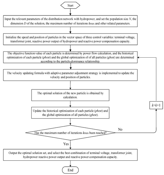
Figure 1.
The flow chart of the RP optimization control method for DN with hydropower based on the improved discrete PSO algorithm.
5. Numerical Test and Analysis
5.1. Basic Data and Simulation Conditions
This paper conducts simulation analysis based on the IEEE-33 buses distribution system to verify the impact of RP output after hydropower integration on the power grid system. The main reason why this paper chooses the IEEE-33 buses distribution system for simulation is that the number of buses and the topological complexity of the system can not only reflect the operation characteristics of the actual distribution network, but also will not lead to excessive calculation, which is suitable for the rapid verification of the proposed method. As shown in Figure 2, the IEEE-33 buses system is a radial DN consisting of a total of 33 buses and 32 branches. The rated voltage of the system is 12.66 kV, with a base power value of 10 MVA. The total load of the system is 3715 + j2300 kVA, and the baseline active power loss of the original system is 203.03 kW. To construct a distribution system incorporating hydropower, small hydropower plants are connected at buses 5, 18, 22, 25, and 33 of the system, the access capacity of each bus is 1000 kW, and the total capacity is 5000 kW. Additionally, six sets of switchable RP compensation devices are installed at buses 12, 27, and 33, with each set having a single-group capacity of 80 kVar. The voltage ratio range of the on-load tap-changing transformers in the system is 0.95 to 1.05, with a unit tap adjustment of 0.05. The allowable voltage range at each bus of the system is 0.9 to 1.1 pu. The system simulations are performed in the Matlab R2014 environment. The PSO algorithm proposed in this paper uses a particle population size of N = 60 and a maximum iteration count of kmax = 100.
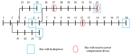
Figure 2.
The IEEE-33 buses distribution system with hydropower.
5.2. Simulation Results and Analysis
According to the seasonal output characteristics of small hydropower stations, the output difference between small hydropower stations in the wet season and dry season is obvious. In the wet season, a small load may cause system overvoltage, and in the dry season, the system voltage may be low when the load is large.
During the wet season, when the system typically operates in spring and autumn, the system load is relatively low. Therefore, when the DN system integrated with small hydropower plants is under low-load conditions during the wet season and without optimized control, the system voltage will severely exceed limits. To address this, RP optimization control methods must be adopted, combining the leading power factor operation of generators with RP compensation devices to regulate the system voltage. To verify the effectiveness of the method proposed in this paper, comparisons are made using no optimization control, the GA, the GWA, the BA, and the improved discrete PSO algorithm proposed in this paper. The RP outputs of the hydropower plants and RP compensation devices are shown in Table 2.
Table 2.
RP compensation scheme in the wet season.
As shown in Table 2, during the high-water period with low loads, the generators operated in leading power factor mode, delivering active power while absorbing RP. Based on the GA, the RP absorbed by the hydropower stations at buses 5, 18, 22, 25, and 33 are 62 kVar, 54 kVar, 97 kVar, 84 kVar, and 35 kVar, respectively. Based on the GWA, the RP absorbed by the hydropower stations at buses 5, 18, 22, 25, and 33 are 58 kVar, 77 kVar, 89 kVar, 92 kVar, and 44 kVar, respectively. Based on the BA, the RP absorbed by the hydropower stations at buses 5, 18, 22, 25, and 33 are 53 kVar, 67 kVar, 92 kVar, 98 kVar, and 62 kVar, respectively. Based on the method proposed in this paper, the RP absorbed by the hydropower stations at buses 5, 18, 22, 25, and 33 are 64 kVar, 72 kVar, 90 kVar, 86 kVar, and 63 kVar, respectively. It can be inferred that during the high-water period, when hydropower units are operating at full capacity, constraints such as temperature rise during leading power factor operation need to be considered. Consequently, the RP absorption by the generators in this mode is relatively low. At this time, all RP compensation devices are deactivated to prevent system overvoltage. The comparison of bus voltages in the system is shown in Figure 3.
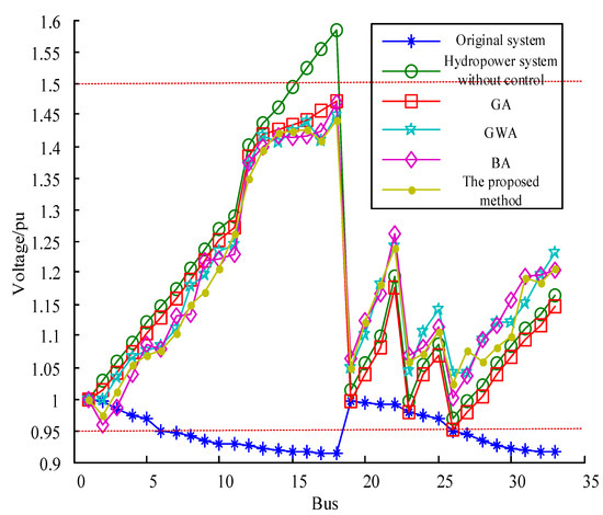
Figure 3.
The comparison of bus voltages for the system in the wet season.
As can be seen from Figure 3, during low-load conditions in the wet season, some buses will exceed the upper limit without optimization control, leading to the phenomenon of bus overvoltage. Since this paper adopts an extended OF, incorporating bus voltage violations as a penalty term into the OF, when using GA, GWA, BA, and the method proposed in this paper for optimization, the voltage at each bus can be controlled within the constrained range. Moreover, as seen from Table 1, under the control of different optimization algorithms, the network losses for GA, GWA, BA, and the method proposed in this paper are 148 kW, 153 kW, 152 kW, and 143 kW, respectively. Compared with GA optimization, the line loss can be reduced by 3.4%. This indicates that the method proposed in this paper not only satisfies the constraint conditions of bus voltages but can also find a more suitable global optimal solution with minimal network losses.
In the heavy load scenario in the dry season, combined with the lagging operation of the generator to generate an RP and RP compensation device, the optimal regulation is carried out. Similarly, to verify the effectiveness of the method proposed in this paper, comparisons are made using no optimization control, the GA, the GWA, the BA, and the improved discrete PSO algorithm proposed in this paper. The RP outputs of the hydropower plants and RP compensation devices are shown in Table 3.
Table 3.
RP compensation scheme in the dry season.
As shown in Table 3, during the low-water period with high loads, the generators operated in lagging operation mode, delivering active power and RP. Based on the GA, the RP delivered by the hydropower stations at buses 5, 18, 22, 25, and 124 are 117 kVar, 223 kVar, 138 kVar, and 162 kVar, respectively. Based on the GWA, the RP delivered by the hydropower stations at buses 5, 18, 22, 25, and 33 are 113 kVar, 124 kVar, 210 kVar, 126 kVar, and 144 kVar, respectively. Based on the BA, the RP delivered by the hydropower stations at buses 5, 18, 22, 25, and 33 are 108 kVar, 135 kVar, 220 kVar, 128 kVar, and 133 kVar, respectively. Based on the method proposed in this paper, the RP delivered by the hydropower stations at buses 5, 18, 22, 25, and 33 are 120 kVar, 118 kVar, 224 kVar, 135 kVar, and 147 kVar, respectively. It can be inferred that during the low-water period, each hydroelectric generating unit operates with a lagging power factor to produce RP, supporting the system voltage. Additionally, various RP compensation devices are activated to supplement the RP in the system. Notably, the optimization schemes for these compensation devices result in the same installed capacity when applying different algorithms. The primary reason for this is that each individual RP compensation device has a relatively large switching capacity, significantly impacting the system’s RP. Therefore, the RP compensation schemes are identical, primarily aiming to achieve better voltage control by optimizing the RP output of the hydroelectric generating units. The comparison of bus voltages in the system is shown in Figure 4.
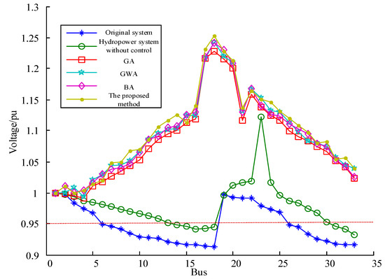
Figure 4.
The comparison of bus voltages for the system in the dry season.
As illustrated in Figure 4, under high-load circumstances in the dry season, some will dip below the lower threshold in the absence of optimization control, resulting in bus under-voltage issues. Likewise, as this paper introduces an expanded OF that includes bus voltage violations as a penalty factor, employing optimization techniques such as GA, GWA, BA, and the method presented herein enables maintaining the voltage at each bus within the specified constraints. Besides, under the control of different optimization algorithms, the network losses for GA, GWA, BA, and the method proposed in this paper are 66 kW, 71 kW, 68 kW, and 57 kW, respectively. Compared with GA optimization, the line loss can be reduced by 13.64%. This demonstrates that the method proposed in this paper not only satisfies the constraint conditions of bus voltages but can also find a more suitable global optimal solution with minimal network losses.
6. Conclusions
Aiming at the problems of increasing network loss and reactive voltage exceeding the limit with hydropower continuously connected to the DN, a RP optimization control method for DN with hydropower based on an improved discrete PSO algorithm is proposed in this paper. The specific characteristics of small hydropower are analyzed, and its mathematical model is established. Considering the constraints of bus voltage and generator RP output, an extended minimum OF for system power loss is established, with bus voltage violation serving as the PF. To improve the global search ability and convergence speed of the traditional discrete PSO algorithm, an improved discrete PSO algorithm is proposed by introducing an adaptive inertia weight. Based on the IEEE-33 buses distribution system as an example, the simulation analysis shows that compared with GA optimization, the line loss can be reduced by 3.4% in the wet season and 13.6% in the dry season. Therefore, the proposed method can effectively reduce the network loss and improve the voltage quality, which verifies the effectiveness and superiority of the proposed method.
As the distribution grid with small hydropower stations incorporated is significantly affected by seasonal factors, this research can effectively improve the voltage quality and stability of the system, address voltage limit violation issues, reduce network losses, enhance the operational economy of the system, and promote the development of clean energy, enabling small hydropower stations to play a greater role in the distribution grid. In the next step, we will consider the integration of multiple types of new energy sources, intensify research on multi-objective optimization algorithms, and develop reactive power optimization control strategies that are better suited for the connection of distributed energy sources.
Author Contributions
Conceptualization, T.L., B.J., S.L., X.K., Y.Z., and H.Z.; methodology, T.L., B.J., S.L., X.K., Y.Z., and H.Z.; software, T.L., B.J., S.L., X.K., Y.Z., and H.Z.; writing—original draft preparation, T.L., B.J., S.L., X.K., Y.Z., and H.Z. All authors have read and agreed to the published version of the manuscript.
Funding
This research received no external funding.
Data Availability Statement
All data used in this paper are illustrated.
Conflicts of Interest
Tao Liu, Bin Jia, Shuangxiang Luo, Xiangcong Kong and Yong Zhou were employed by the State Grid Hubei Electric Power Company Limited Enshi Electric Power Supply Company. The remaining authors declare that the research was conducted in the absence of any commercial or financial relationships that could be construed as a potential conflict of interest.
Nomenclature
| DN | Distribution network |
| RP | Reactive power |
| PSO | Particle swarm optimization |
| GA | Genetic algorithm |
| OF | Objective function |
| PF | Penalty function |
| GWA | Grey wolf algorithm |
| EPA | Evolutionary programming algorithms |
| BA | Bat algorithm |
| PF | Penalty function |
References
- Yang, L.; Sun, X.; Cao, X.; Chen, M.; Guan, X. Joint chance-constrained coordinated scheduling for electricity-heat coupled systems considering hydrogen storage. Energy Internet 2024, 1, 99–111. [Google Scholar] [CrossRef]
- Liu, J.-H.; Cheng, J.-S. Online Voltage Security Enhancement Using Voltage Sensitivity-Based Coherent Reactive Power Control in Multi-Area Wind Power Generation Systems. IEEE Trans. Power Syst. 2021, 36, 2729–2732. [Google Scholar] [CrossRef]
- Tong, H.; Zeng, X.; Yu, K.; Zhou, Z. A Fault Identification Method for Animal Electric Shocks Considering Unstable Contact Situations in Low-Voltage Distribution Grids. IEEE Trans. Ind. Inform. 2025, 21, 4039–4050. [Google Scholar] [CrossRef]
- Zhang, S.; Ma, G.; Chen, S.; Huang, W.; Yang, Y. Hydropower Pricing Options for Cross-Border Electricity Trading in China Based on Bi-Level Optimization. IEEE Access 2022, 10, 83869–83883. [Google Scholar] [CrossRef]
- Yang, W.; Norrlund, P.; Saarinen, L.; Yang, J.; Zeng, W.; Lundin, U. Wear Reduction for Hydropower Turbines Considering Frequency Quality of Power Systems: A Study on Controller Filters. IEEE Trans. Power Syst. 2017, 32, 1191–1201. [Google Scholar] [CrossRef]
- Ho, C.N.M.; Lam, C.-S. Editorial for the special issue on power quality conditioning in modern power grids integrated emerging power electronic systems. CPSS Trans. Power Electron. Appl. 2021, 6, 191–192. [Google Scholar]
- Ge, Y.; Hu, H.; Huang, Y.; Wang, K.; Chen, J.; He, Z. Quadratic Sensitivity Models for Flexible Power Quality Improvement in AC Electrified Railways. IEEE Trans. Power Electron. 2023, 38, 2844–2849. [Google Scholar] [CrossRef]
- Lai, J.; Chen, M.; Dai, X.; Zhao, N. Energy Management Strategy Adopting Power Transfer Device Considering Power Quality Improvement and Regenerative Braking Energy Utilization for Double-Modes Traction System. CPSS Trans. Power Electron. Appl. 2022, 7, 103–111. [Google Scholar] [CrossRef]
- Liao, Y.; Yang, W.; Wang, Z.; Huang, Y.; Chung, C.Y. Mechanism of Primary Frequency Regulation for Battery Hybridization in Hydropower Plant. CSEE J. Power Energy Syst. 2024, 10, 2127–2137. [Google Scholar]
- Nayak, B.P.; Chelliah, T.R.; Jena, P. RTDS Implementation and Stability Analysis of PSS4B Enabled Large Hydropower Plant Connected to a Series Compensated High Voltage Network. IEEE Trans. Ind. Appl. 2024, 60, 5499–5509. [Google Scholar] [CrossRef]
- Kumari, R.; Prabhakaran, K.K.; Desingu, K.; Chelliah, T.R.; Sarma, S.V.A. Improved Hydroturbine Control and Future Prospects of Variable Speed Hydropower Plant. IEEE Trans. Ind. Appl. 2021, 57, 941–952. [Google Scholar] [CrossRef]
- Fan, Q.; Li, G.; Jiang, X.; Ma, B.; Chen, T.; Li, M. Intelligent Control Method and System for Vibroflotation Construction in Hydropower Engineering. J. Intell. Constr. 2024, 2, 1–14. [Google Scholar] [CrossRef]
- Liu, Y.; Wu, L.; Yang, Y.; Chen, Y.; Baldick, R.; Bo, R. Secured Reserve Scheduling of Pumped-Storage Hydropower Plants in ISO Day-Ahead Market. IEEE Trans. Power Syst. 2021, 36, 5722–5733. [Google Scholar] [CrossRef]
- Ojo, Y.; Alam, S.M.S.; Balliet, W.H.; Mosier, T.M. Frequency Response Improvement in a Standalone Small Hydropower Plant Using Battery Storage. IEEE Trans. Energy Convers. 2024, 39, 2701–2717. [Google Scholar] [CrossRef]
- Kumari, R.; Chelliah, T.R. Impact Analysis of Sensor Cyber-Attacks on Grid-Tied Variable Speed Hydropower Plants. IEEE Trans. Ind. Appl. 2023, 59, 7725–7734. [Google Scholar] [CrossRef]
- Zhao, Q.; Li, C. Two-Stage Multi-Swarm Particle Swarm Optimizer for Unconstrained and Constrained Global Optimization. IEEE Access 2020, 8, 124905–124927. [Google Scholar] [CrossRef]
- Deng, L.; Song, L.; Sun, G. A Competitive Particle Swarm Algorithm Based on Vector Angles for Multi-Objective Optimization. IEEE Access 2021, 9, 89741–89756. [Google Scholar] [CrossRef]
- Yi, Y.; Wang, Z.; Shi, Y.; Song, Z.; Zhao, B. Convergence-Driven Adaptive Many-Objective Particle Swarm Optimization. IEEE Access 2025, 13, 5129–5144. [Google Scholar] [CrossRef]
- Zhang, D.; Jiang, M. Parallel discrete lion swarm optimization algorithm for solving traveling salesman problem. J. Syst. Eng. Electron. 2020, 31, 751–760. [Google Scholar]
- Feng, Q.; Li, Q.; Wang, H.; Feng, Y.; Pan, Y. Two-Stage Adaptive Constrained Particle Swarm Optimization Based on Bi-Objective Method. IEEE Access 2020, 8, 150647–150664. [Google Scholar] [CrossRef]
- Emambocus, B.A.S.; Jasser, M.B.; Hamzah, M.; Mustapha, A.; Amphawan, A. An Enhanced Swap Sequence-Based Particle Swarm Optimization Algorithm to Solve TSP. IEEE Access 2021, 9, 164820–164836. [Google Scholar] [CrossRef]
- Liu, X.; Zhang, P.; Fang, H.; Zhou, Y. Multi-Objective Reactive Power Optimization Based on Improved Particle Swarm Optimization With ε-Greedy Strategy and Pareto Archive Algorithm. IEEE Access 2021, 9, 65650–65659. [Google Scholar] [CrossRef]
- Feng, N.; Feng, Y.; Su, Y.; Zhang, Y.; Niu, T. Dynamic Reactive Power Optimization Strategy for AC/DC Hybrid Power Grid Considering Different Wind Power Penetration Levels. IEEE Access 2024, 12, 187471–187482. [Google Scholar] [CrossRef]
- Hui, Q.; Teng, Y.; Zuo, H.; Chen, Z. Reactive power multi-objective optimization for multi-terminal AC/DC interconnected power systems under wind power fluctuation. CSEE J. Power Energy Syst. 2020, 6, 630–637. [Google Scholar]
- Ding, T.; Liu, S.; Yuan, W.; Bie, Z.; Zeng, B. A Two-Stage Robust Reactive Power Optimization Considering Uncertain Wind Power Integration in Active Distribution Networks. IEEE Trans. Sustain. Energy 2016, 7, 301–311. [Google Scholar] [CrossRef]
- Wang, P.; Wu, Q.; Huang, S.; Li, C.; Zhou, B. ADMM-based Distributed Active and Reactive Power Control for Regional AC Power Grid with Wind Farms. J. Mod. Power Syst. Clean Energy 2022, 10, 588–596. [Google Scholar] [CrossRef]
- Ai, Y.; Du, M.; Pan, Z.; Li, G. The optimization of reactive power for distribution network with PV generation based on NSGA-III. CPSS Trans. Power Electron. Appl. 2021, 6, 193–200. [Google Scholar] [CrossRef]
- Xia, Y.; Li, Z.; Xi, Y.; Wu, G.; Peng, W.; Mu, L. Accurate Fault Location Method for Multiple Faults in Transmission Networks Using Travelling Waves. IEEE Trans. Ind. Inform. 2024, 20, 8717–8728. [Google Scholar] [CrossRef]
- Ibrahim, T.; Rubira, T.T.D.; Rosso, A.D.; Patel, M.; Guggilam, S.; Mohamed, A.A. Alternating Optimization Approach for Voltage-Secure Multi-Period Optimal Reactive Power Dispatch. IEEE Trans. Power Syst. 2022, 37, 3805–3816. [Google Scholar] [CrossRef]
Disclaimer/Publisher’s Note: The statements, opinions and data contained in all publications are solely those of the individual author(s) and contributor(s) and not of MDPI and/or the editor(s). MDPI and/or the editor(s) disclaim responsibility for any injury to people or property resulting from any ideas, methods, instructions or products referred to in the content. |
© 2025 by the authors. Licensee MDPI, Basel, Switzerland. This article is an open access article distributed under the terms and conditions of the Creative Commons Attribution (CC BY) license (https://creativecommons.org/licenses/by/4.0/).