Abstract
A brick kiln was experimentally studied to measure the transient temperature of hot gases and the compressive strength of the bricks, using pine wood as fuel, in order to evaluate the thermal performance of the actual system. In addition, a transient combustion model based on computational fluid dynamics (CFD) was used to simulate the combustion of natural gas in the brick kiln as a hypothetical case, with the aim of investigating the potential benefits of fuel switching. The theoretical stoichiometric combustion of both pine wood and natural gas was employed to compare the mole fractions and the adiabatic flame temperature. Also, the transient hot gas temperature obtained from the experimental wood-fired kiln were compared with those from the simulated natural gas-fired kiln. Furthermore, numerical simulations were carried out to obtain the transient hot gas temperature and NOx emissions under stoichiometric, fuel-rich, and excess air conditions. The results of CO2 mole fractions from stoichiometric combustion demonstrate that natural gas may represent a cleaner alternative for use in brick kilns, due to a 44.08% reduction in emissions. Contour plots of transient hot gases temperature, velocity, and CO2 emission inside the kiln are presented. Moreover, the time-dependent emissions of CO2, H2O, and CO at the kiln outlet are shown. It can be concluded that the presence of CO mole fractions at the kiln outlet suggests that the transient combustion process could be further improved. The low firing efficiency of bricks and the thermal efficiency obtained are attributed to uneven temperatures distributions inside the kiln. Moreover, hot gas temperature and NOx emissions were found to be higher under stoichiometric conditions than under fuel-rich or excess of air conditions. Therefore, this work could be useful for improving the thermal–hydraulic and emissions performance of brick kilns, as well as for future kiln design improvements.
1. Introduction
The production of ceramic and brick materials involves crucial stages such as drying, firing, and cooling, which are typically carried out in industrial furnaces or different kind of kilns widely used across the sector (Refaey et al. [1]). In the application of industrial furnaces, a wide variety of fuels have been used in both industrial and lab-scale experiments. However, natural gas, as a gaseous fuel, is considered one of the most advantageous fuels for combustion applications (Tu et al. [2]). In the application of tunnel kilns, natural gas is intensively used in the firing of ceramic products (Hussnain et al. [3]). In the brickyard industry, kilns can be operated using a variety of fuels, including dung, coconut shells, charcoal, wood, and sawdust. Unfortunately, the use of hazardous materials, such as unusable tires, engine oil, plastics, and electronic waste, still persists in many artisanal kilns (Berumen-Rodríguez et al. [4] and INECC [5]). In this context, natural gas emerges as a more efficient, cleaner, and more sustainable alternative when compared to pine wood and other hazardous materials commonly used in artisanal brick production. However, the initial investment may be a limiting factor due to the cost and complexity of adapting existing kiln infrastructure, such as specialized burners, pressure regulators, gas pipelines, and safety systems, to natural gas combustion; nevertheless, the benefits in product quality, reduced polluting emissions, and shorter production times could justify its gradual implementation.
It is important to note that the use of industrial furnaces, tunnel kilns, and brick kilns generate emissions that enhance the greenhouse effect and many other types of contamination, such as soil, plants, and human health. The brick industry in Bangladesh, Pakistan, China, and India accounts for 75% of the air pollution generated by this industry (Ahmad et al. [6]). In developing countries, the lack of regulatory standards aggravates this problem (Dothe et al. [7]). It has been stated that emissions of brick kilns impact vegetation (Khanoranga & Khalid [8]). Soil contamination is another significant concern. It was found that plants absorbed elevated levels of iron (Fe) and manganese (Mn) within 500 to 1000 m from brick kilns (Farhad et al. [9]). Therefore, contamination of brick kilns generates risks for agriculture near these facilities. Also, regarding human health impacts, brick kiln workers face a high risk of cancer due to exposure to polycyclic aromatic hydrocarbons (PAHs) through ingestion and dermal contact (Kamal et al. [10]). Communities near brickyards experienced adverse health effects, prompting recommendations to site kilns at least 1 to 2 km away from residential zones (Brooks et al. [11]). Moreover, emissions from brick kilns have damaged soil quality and deteriorated the ecological environment. Thus, brick kilns necessitate the implementation of emission control strategies and soil remediation efforts (Haque et al. [12]).
According to the literature reviewed above, investigations must be conducted on brick kilns to improve the brickyard industry. In this sense, some studies of brick furnaces and brick kilns have been carried out by means of experimental tests, modeling, and computational fluid dynamics (CFD) with the aim of improving the performance of brick kilns. Among these studies, artisanal kilns, tunnel kilns, industrial furnaces, and pilot-scale furnaces are the most discussed. Refaey et al. [1] made both CFD study and experimental tests focusing on the heat transfer by convection in a brick tunnel kiln during the cooling process. They proposed a new brick arrangement using CFD, achieving a 15.3% increase in the Nusselt number. Refaey et al. [13] performed a thermal study under transient condition in a brick tunnel kiln, and U-shape guide vanes were investigated for different attack angles, finding that a 135° angle provided better coefficient of heat transfer. Refaey et al. [14] analyzed vane types in a brick tunnel kiln and concluded that the use of U-shaped vanes had a greater impact on thermal performance compared to side-wall vanes. Refaey et al. [15] achieved a 94.5% enhancement in the Nusselt number using a 135° vane angle in a middle stack arrangement in a brick tunnel kiln. Refaey et al. [16] validated CFD simulations using the k-ω turbulent model, revealing non-homogeneous airflow distribution in the kiln. Al-Hasnawi et al. [17] used CFD and k-ε turbulent model to study the mixing of flow, achieving good agreement with analytical results. Alonso-Romero et al. [18] carried out a transient thermal analysis for the firing process in a brick kiln, using different numerical approaches and the k-ε turbulent model. It was concluded that the Ideal Gas Law (IGL) numerical model provided the best thermal and hydraulic performance, as it showed the best agreement with experimental data. All the above-mentioned numerical studies simplify hot gases as hot air (pollution emissions are not reported), and only a few numerical works have focused on the combustion for the firing process. Ngom et al. [19] applied CFD to simulate transient brick firing using the standard k-ε turbulent model and the Eddy Dissipation turbulent combustion model, focusing on fluid flow, temperature, and O2 distribution, demonstrating CFD’s usefulness in kiln designs; however, the firing process lasted 4 h and the number of fired bricks inside the kiln were not mentioned. Beyene et al. [20] used CFD to study brick firing with biogas and the standard k-ε turbulent model, finding that bricks farther away from the combustion chamber had lower temperatures (non-homogeneous distribution of temperatures) and required longer firing times; however, only 28 bricks were considered.
On the other hand, recently, Arvanitidis et al. [21,22] conducted a study to model, optimize, and control an industrial-scale tunnel kiln with ceramic material under different production demands. The work demonstrated an outstanding system response in terms of firing curves adapted to production rates and quality targets, resulting in a meaningful decrease in operational costs. Besides the importance of improving thermal performance and operating costs, it is important to obtain good compression strength; thus, some investigations have been focused on the incorporation of alternative materials that enhance or reduce the compression strength. Cansee and Pattiya [23] conducted an experimental investigation on the incorporation of three types of solid media, alumina balls, clay balls, and sandstone sheets, positioned between bricks during the firing stage to enhance product quality. Their findings indicated that the combined use of sandstone sheets and alumina balls resulted in a doubling of the bricks’ compressive strength. Vasić et al. [24] studied the compressive strength of some clays. They found that the compressive strength ranged from 10.79 MPa to 44.13 MPa. Riaz et al. [25] evaluated the incorporation of brick kiln dust, BKD, up to 25% in clay bricks, resulting in decreased compressive strength from 9.13 MPa to 5.95 MPa. Kazmi et al. [26] studied the addition of sugar bagasse ash, SBA, and rice husk ash, RHA, in various dosages in clay, resulting in compressive strengths of 9.44 MPa for standard bricks and 5.01 MPa and 5.33 MPa for bricks with 15% SBA and RHA, respectively. Gencel et al. [27] studied the incorporation of pumice up to 40% to improve thermal conductivity, finding compressive strengths between 18.5 MPa and 32.9 MPa.
In this work, experimental tests were conducted using pine wood as fuel to obtain transient hot gas temperatures and compressive strength. Meanwhile, natural gas was considered as fuel in a transient combustion model by CFD (TC model) to simulate the firing process in a brick kiln loaded with 8310 bricks. The use of natural gas in the CFD simulations was treated as a hypothetical case aiming at investigating the potential benefits of fuel switching. Additionally, a theoretical comparison of CO2, H2O, and N2 emissions, as well as adiabatic flame temperatures for pine wood and natural gas combustion, was performed. Furthermore, the transient hot gas temperatures inside the brick kiln predicted by CFD simulations were compared with experimental temperature measurements. Numerical contour plots of transient hot gas temperatures, velocity fields, and CO2 emissions inside the kiln are shown throughout the entire 14-h firing process. Time-dependent emissions of CO2, H2O, and CO at the kiln outlet are also reported. Moreover, CFD simulations were carried out under stoichiometric, fuel-rich, and excess air conditions to analyze the effects on transient hot gas temperatures and NOx emissions.
2. Experimental Setup
Artisanal kiln construction relies on traditional knowledge that has been transmitted across generations. These kilns are often built using locally available clay and mud (low capital investment), and their design emphasizes simplicity, ease of construction, and low operational costs (burning wood, coal, among others). The structural simplicity makes them accessible and economically viable for informal producers in many developing countries.
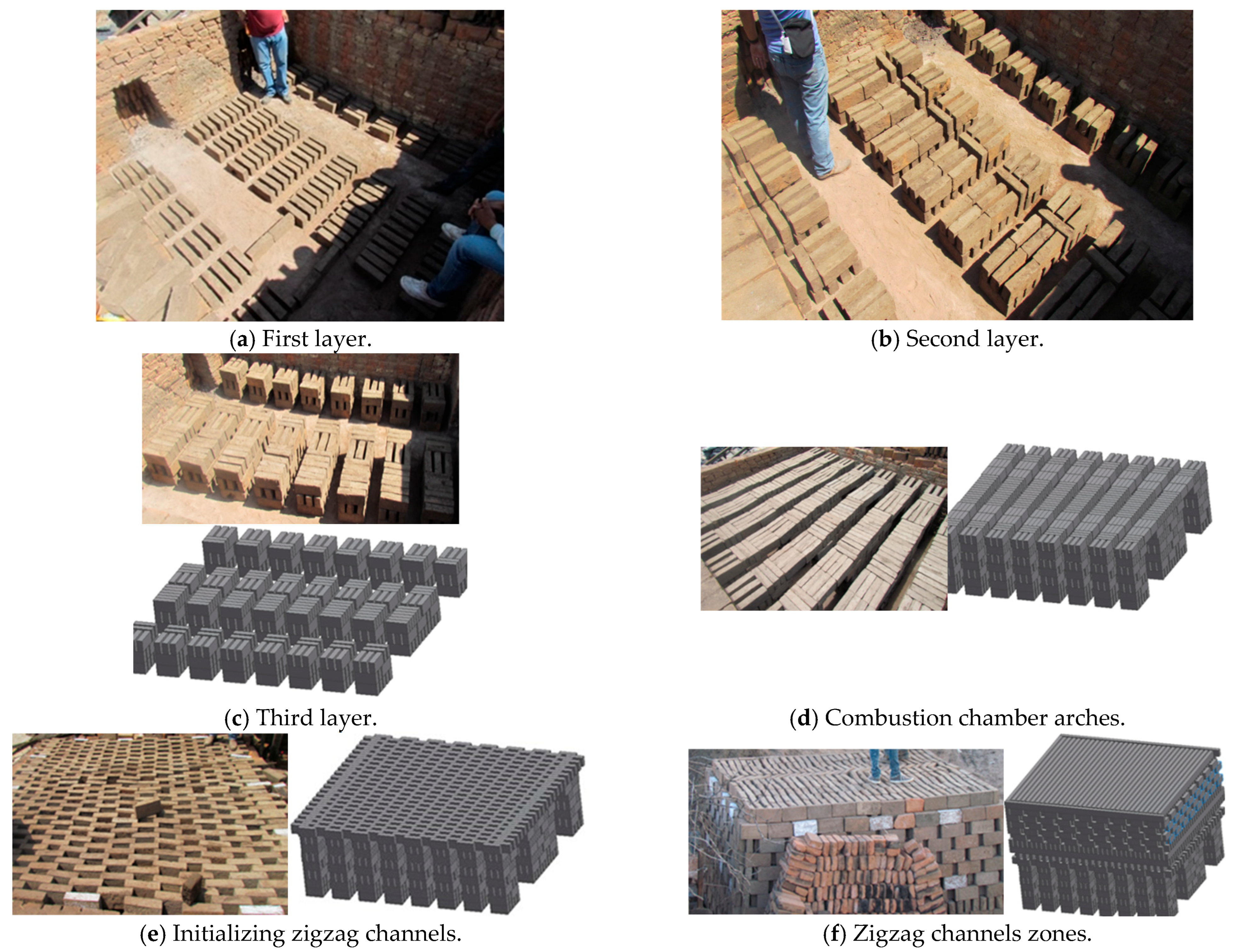
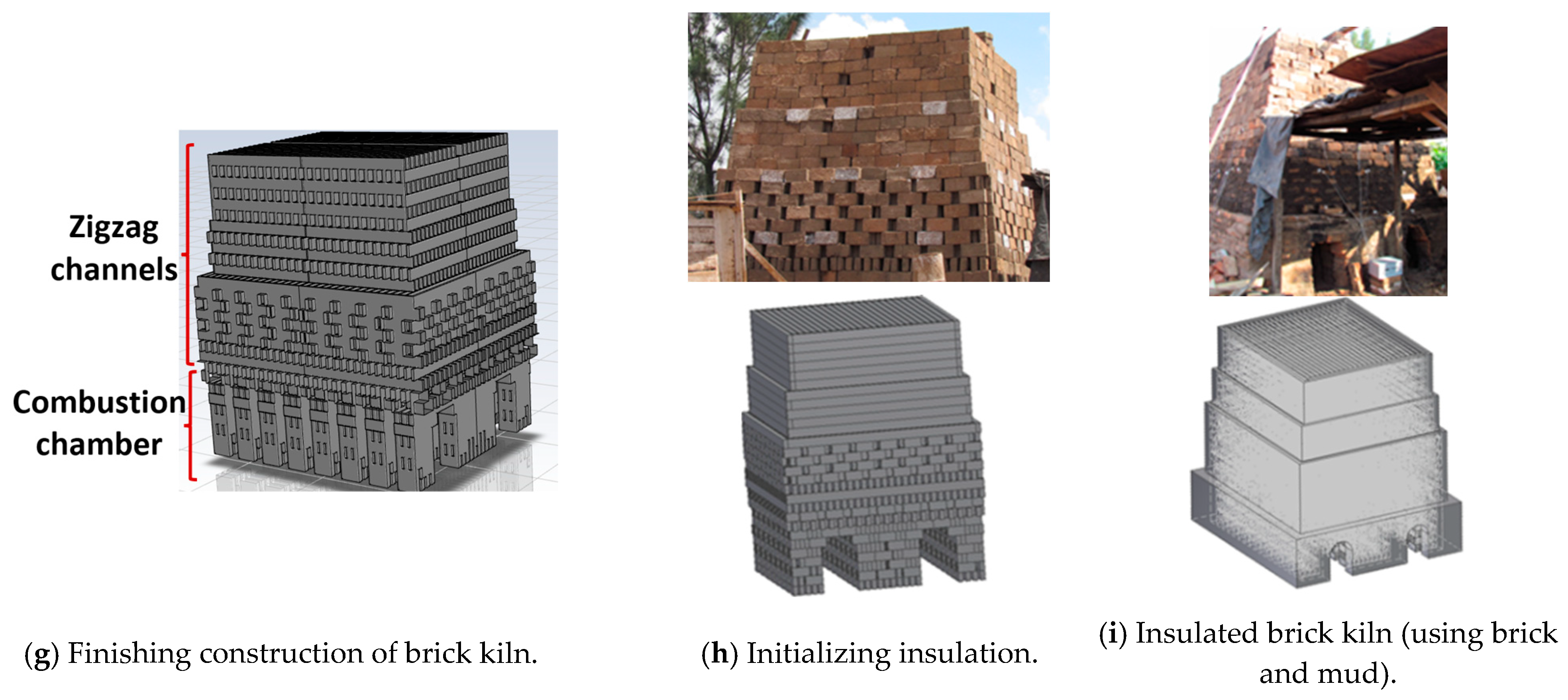
Two experimental tests were made under the same construction of the kiln and operational conditions. The kiln was constructed layer by layer with bricks arranged in both longitudinal and transverse placements. The kiln has two key characteristics: the first is that the combustion chamber is constructed by the initial seven bricks’ layers (Figure 1a–d) (some images generated with the SOLIDWORKS 2015 software were used to provide a better explanation); the second is that the successive layers result in the formation of zigzag channels (Figure 1e–g), where the hot gases flow, and it is where there is more quantity of bricks. The kiln studied in this work consisted of 30 layers in total and it was loaded with 8310 bricks (Table 1); each brick had the following dimensions: 0.265 m × 0.07 m × 0.13 m in length, width, and height, respectively. The kiln’s insulation consisted of a 0.07 m thick layer of mud and bricks (Figure 1h,i). The experimental brick kiln had a total volume of 39.8 m3, with external dimensions of 3.0 m × 3.4 m × 3.9 m in length, width, and height, respectively (Figure 1i).


Figure 1.
Construction of the brick kiln.

Table 1.
Layers and number of bricks per layer.
The monitoring of the temperature of hot gases within the kiln was performed with two experimental tests. Fifty-two K-type thermocouples were set up evenly throughout the interior of the brick kiln (Figure 2a,b). Temperature monitoring was conducted using 4 dataloggers (Figure 2a), created by the electronics laboratory of CIATEC. It is worth mentioning that CIATEC’s laboratory is accredited and supported by the Mexican Accreditation Entity (Entidad Mexicana de Acreditación, EMA), ensuring compliance with national and international standards. Each datalogger was responsible for recording temperatures of hot gases on all four sides of the kiln (North, West, East, and South). Temperatures were recorded over time using a 120-s sampling interval. An S-type thermocouple (Isotech, Hatfield, PA, USA), connected to a Fluke-brand voltage measurement device (54 II Model), was used to calibrate the K-type thermocouples, providing an accuracy of ±0.7 K. The total uncertainty of the system was ±2.3 K.
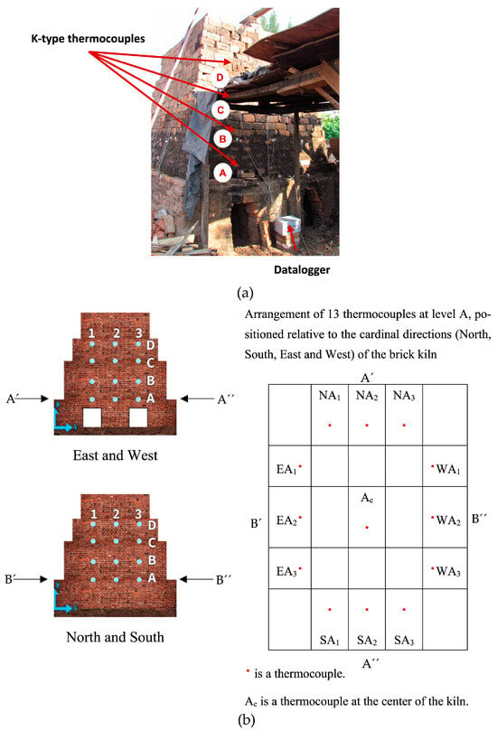
Figure 2.
(a) Installation of K-type thermocouples inside the brick kiln and dataloggers located around the brick kiln and (b) distribution of K-type thermocouples.
3. Transient Combustion Model
The transient combustion (TC) model requires to solve the fluid flow through the equations of Continuity, Navier–Stokes, and Standard - Turbulence model (Al-Hasnawi et al. [17], Ngom et al. [19], and Beyene et al. [20]), as shown in the Equations (1)–(7):
where the variable is the density, is the time, and τ(t) is the Reynolds stress. It can be expressed by Equation (3) in terms of the average velocity fluctuations (), turbulent kinetic energy (), identity tensor (), and the turbulent dynamic eddy viscosity ().
The k − ε turbulence model, first proposed by Launder and Spalding in 1972 [28], is used in its standard form to quantify mixing effects, as described in Equations (4) and (5). This model has proven effective in predicting both thermal and fluid flow behavior in kilns (Al-Hasnawi et al. [17], Ngom et al. [19], and Beyene et al. [20]). These equations describe the turbulent kinetic energy () and the dissipation rate of turbulent kinetic energy ().
where represents the production of turbulent kinetic energy resulting from velocity gradients, as defined in Equation (6). The turbulent viscosity, on the other hand, is expressed in Equation (7) as a function of the main variables.
where , , and are constants of the model, while the parameters σκ and σε are the turbulent Prandtl numbers for k and , respectively. The values of the constants are ; ; ; ; (Launder and Spalding [28]).
Additionally, energy Equation (8) solves the temperature by the convective heat flow of hot gases inside the zigzag channels and the conduction heat transfer in the bricks (Refaey et al. [16]).
Moreover, to solve the production of pollution species, chemical equilibrium is modeled using the mixture fraction approach, where complex chemical reactions are simplified into one or two conserved mixture fractions. In this framework, all thermo-chemical scalars are considered functions of the mixture fraction (ƒ) in Equations (9) and (10). It is widely accepted for turbulent flows where turbulent convection significantly exceeds molecular diffusion.
In addition, Equation (11) has to be solved for the mixture fraction variance . The mixture fraction variance is employed in the closure model to describe turbulence–chemistry interactions. The equations for individual species are not solved. Instead, species concentrations are derived from the predicted mixture fraction fields. The thermochemistry calculations were performed in a preprocessing step and then tabulated for look-up in ANSYS FLUENT®. The interaction between chemistry and turbulence was considered via an assumed-shape Probability Density Function (PDF) (Alfaro-Ayala et al. [29] and Alfaro-Ayala et al. [30]).
where . The default values for the constant and are 0.85, 2.86, and 2.0, respectively.
The CFD simulations of the brick firing process inside the kiln were performed using the commercial software ANSYS Fluent® v20. A transient solver was employed. Governing equations for flow, with pressure–velocity coupling, were solved by the SIMPLE algorithm. Pressure was discretized using a standard scheme, while second-order upwind discretization was applied to both momentum and energy equations. Turbulent kinetic energy and its dissipation rate used a first-order upwind scheme. Mixture fraction used a second-order forward discretization scheme (Patankar [31]).
3.1. Stoichiometric Combustion Reactions and Adiabatic Flame Temperature
The global stoichiometric combustion reactions are shown in Table 2. For pine wood, the amount of each element C, H, O, and N was obtained from Milićević et al. [32] and Backreedy et al. [33]. Pine wood is one of the principal fuels used in artisanal brick kilns in our country. Natural gas was considered as methane (CH4) only (Alfaro-Ayala et al. [30]). Natural gas offers a significantly more efficient, environmentally friendly, and sustainable solution when compared to pine wood and other hazardous fuels employed in artisanal brick production (Berumen-Rodriguez et al. [4] and INECC [5]). These stoichiometric combustion reactions assume complete combustion, producing CO2 and H2O as the only products, while N2 is treated as an inert species.
Table 2.
Stoichiometric combustion reactions.
The air–fuel (AF) ratio is used in the combustion process to quantify the amount of fuel and air as follows:
where is the mass flow rate of air, is the mass flow rate of fuel, N is the number of moles, and M is the molar mass.
To obtain the adiabatic flame temperature (Taf) of the stoichiometric combustion reactions, it is convenient to solve the first law of thermodynamics as follows:
where and represent the number of moles of the reactant r and the product p, respectively; is enthalpy of formation at the standard reference state; is the sensible enthalpy at the specified state; and the sensible enthalpy at the standard reference state.
The percentages of excess and deficiency of air are calculated using the actual and stoichiometric air–fuel ratios, as shown in Equations (14) and (15):
3.2. Geometry and Mesh of the Kiln
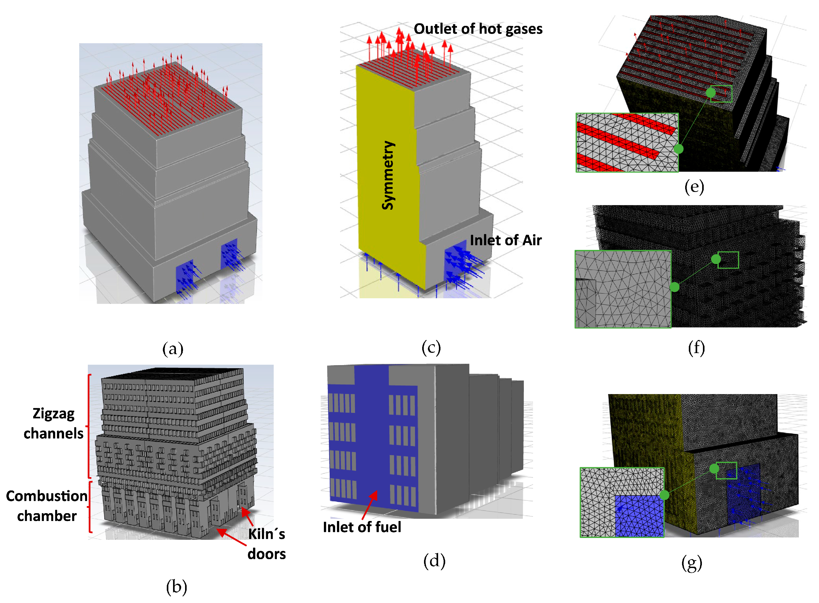
Figure 3a,b show the geometric model of the kiln, which comprised 8310 bricks arranged in 30 layers, matching the experimental construction (Figure 1). Additionally, the CFD simulations were performed on only one-quarter of the kiln geometry, leveraging the symmetry conditions present (Figure 3a–c). The bottom of the kiln was considered for the entrance of the fuel (Figure 3d) and the kiln’s door was considered for the inlet of air (Figure 3b,c). The mesh consisted of 11,236,917 cells of only tetrahedrons (Figure 3e–g), with a mesh size of 0.02 m to ensure the independence of the results (Alonso-Romero et al. [18]).

Figure 3.
(a) Geometry of the entire brick kiln. (b) Bricks. (c) ¼ of the symmetrical model of the brick kiln. (d) Inlet of fuel and (e) outlet. (f) Mesh of bricks and (g) mesh of the brick kiln at the inlet of air.
3.3. Boundary Conditions and Assumptions
The non-slip condition was defined on all the walls of the bricks (Figure 3b). Symmetry conditions were applied to generate the full geometric model of the brick kiln (Figure 3c). Atmospheric pressure was imposed as boundary condition at the kiln’s outlet (Figure 3c). A mass flow rate of air of 2.04 kg/s was set at the kiln’s door (Figure 3b,c) and a mass flow rate of natural gas of 0.0654 kg/s was set at the bottom of the brick kiln (Figure 3d). It had an AF ratio of 31.2 with an excess of air of 81.5%. The initial temperature throughout the entire domain, including the air, bricks, and insulating walls of the kiln, was set to 293.15 K, and the velocity within the fluid domain was set to zero. A time step of 3600 s was used. The properties of the bricks remained constant during the firing process (14 h): thermal conductivity of 0.66 W/m∙K, density of 1520 kg/m3, and specific heat of 790 J/kg∙K (Alonso-Romero et al. [18] and Çengel and Ghajar [34]). The thickness of the insulating walls (bricks and mud) was 0.07 m.
To ensure good results in the numerical simulation, some assumptions were adopted in this study as follows:
- Transient state, to capture the time-dependent behavior of the variables.
- Turbulent flow regime, given the nature of the fluid flow.
- Bricks inside the kiln are considered thermal loads to account for heat transfer by conduction.
- Combustion modeling included six chemical species, CH4, CO2, H2O, CO, O2, and N2, representing the main reactants and products involved.
- Symmetry was assumed in the kiln geometry, allowing the simulation of only one quarter of the full domain to reduce computational cost.
- Adiabatic wall conditions were applied, assuming no heat loss through the kiln boundaries.
- No radiation model was included; radiative heat transfer was neglected to simplify the simulation and reduce the computational time.
4. Results of Experimental Transient Temperature of Hot Gases
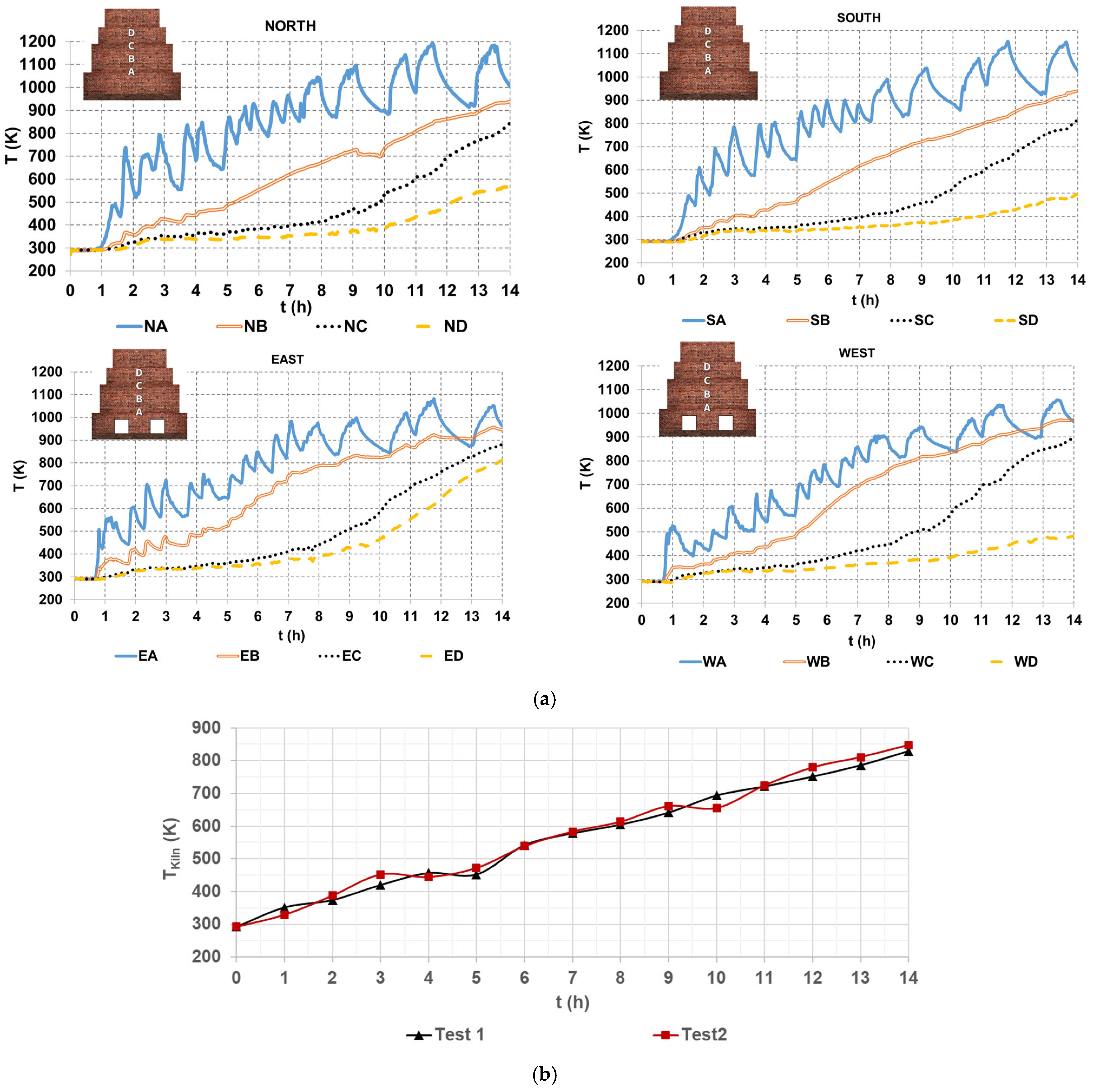
Figure 4a shows four graphs of temperature profiles of hot gases within the brick kiln, referring to the North, South, East, and West sides of the brick kiln, each subdivided into four levels, from A to D. The temperature at each level is the average of readings from three thermocouples positioned on the corresponding side and level of the brick kiln (Figure 2). For instance, NA denotes the temperature measured at the North side and level A, and similarly to the others. The data in Figure 4a shows an oscillatory temperature pattern at level A, which can be attributed to its location near the combustion chamber, in which the turbulent gas dynamics are more pronounced. Conversely, temperatures at levels B, C, and D are lower, due to a low gas flow rate through the narrow zigzag channels; this decreases the convective heat transfer, particularly near the upper section of the kiln (level D), as it was mentioned by Beyene et al. [20].
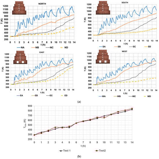
Figure 4.
Hot gases temperatures (a) on the sides of the brick kiln and (b) average value of all the thermocouples.
The highest temperature was approximately 1200 K at level A on the North side of the brick kiln, occurring at 11.5 h. On the other hand, the lowest temperature, around 500 K, was observed on the West side of the brick kiln at 14 h. At the end of the firing process (14 h), temperatures reached approximately 1000 K at level A, between 900 K and 1000 K at level B, between 800 K and 900 K at level C, and between 400 K and 500 K at level D on the South and West sides. On the East side, level C recorded temperatures between 800 K and 900 K, while on the North side, level C exhibited temperatures between 500 K and 600 K. These temperature variations can be attributed to the kiln’s internal geometry, particularly the arrangement of the zigzag channels, which influences gas flow distribution and heat transfer. An important observation concerning the kiln’s thermal performance is the non-uniform temperature over time, mainly due to the uneven distribution of hot gases flow across the zigzag channels of the kiln. The non-homogeneous temperature and fluid flow are important issues to be investigated in brick kilns and furnaces in future works, as mentioned by Refaey et al. [16], Beyene et al. [20], and Alonso-Romero et al. [18].
Figure 4b shows an average value of the hot gas temperature that was measured with all 52 K type thermocouples. A minimum value of 293.15 K and a maximum value of temperature of the hot gases of 829.32 K and 847.41 K for test 1 and test 2, respectively, can be observed.
4.1. Results of Experimental Compressive Strength of Bricks
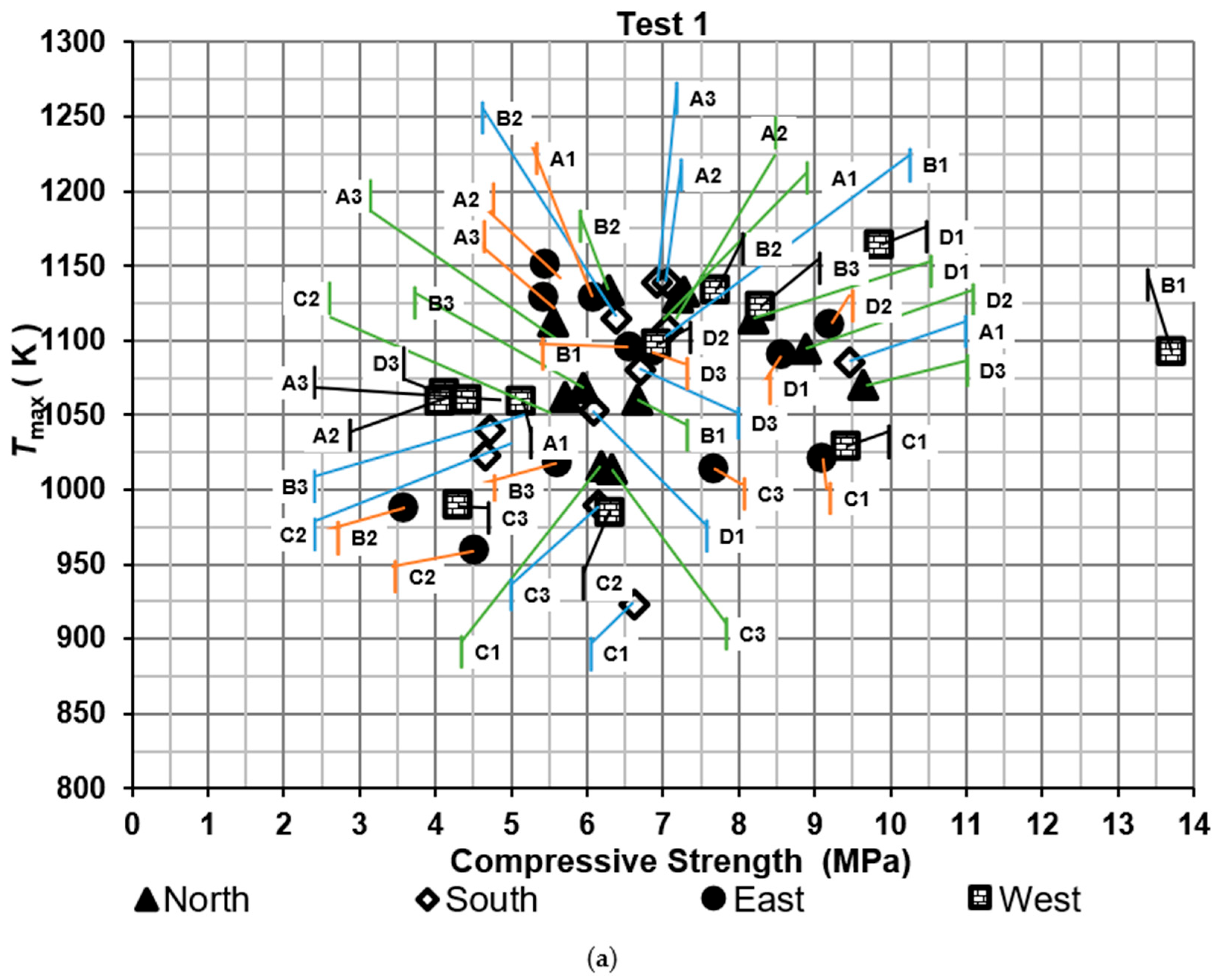
Compressive strengths of bricks were determined for the two tests, as shown in Figure 5. It shows the maximum temperature of the hot gases measured near the brick tested against compressive strength. The results were compared with the Mexican standard NMX-C-036-ONNCCE-2013 to verify whether the values met the required criteria. According to this standard, the compressive strength of the bricks should exceed 6.87 MPa. Moreover, the efficiency was evaluated based on the proportion of bricks that met the Mexican standard, referred to as the firing efficiency of bricks. On the other hand, thermal efficiency was determined using specific energy consumption metrics.

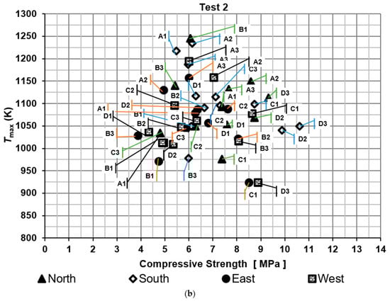
Figure 5.
Compressive strength of the bricks: (a) test 1 and (b) test 2.
For the first test, the percentages of bricks that met the standard were 41.7%, 36.4%, 55.6%, and 66.7% for the North, South, East, and West sides of the brick kiln, respectively. The lowest compressive strength was obtained in a brick located on the East side of the brick kiln at level B2 with a value of 3.59 MPa and the highest compressive strength was obtained on the West side of the brick kiln at level B1 with a value of 13.70 MPa.
For the second test, the percentages of bricks that meet the standard were 58.3%, 50.0%, 41.7%, and 33.3% for the North, South, East, and West side of the brick kiln, respectively. The lowest compressive strength was obtained in a brick located on the East side of the brick kiln at level B3 with a value of 3.86 MPa and the highest compressive strength was obtained on the South side of the brick kiln at level D3 with a value of 10.6 MPa.
The firing efficiency of bricks, which met the standard, was 50.1% for test 1 and 45.8% for test 2. On the other hand, the thermal efficiency was around 24.4%. One of the main factors that contributes to these low percentages of efficiencies is the non-uniform temperature distribution of the hot gases inside the kiln.
It is worth noting that other studies reported in the literature have shown similar compressive strength values, and in some cases, even less restrictive requirements for meeting local standards. For instance, Dothe et al. [7] obtained compressive strengths around 5.90 MPa using coal and a 3:2 mixture of coal and sludge. Riaz et al. [25] stated that, according to Pakistan’s building code, the compressive strength should exceed only 5 MPa. Moreover, Karaman et al. [35] concluded that the firing time had no significant effect on compressive strength, whereas the compressive strength increased with higher firing temperatures within the range of 973.15 K to 1373.15 K.
4.2. Theoretical Comparison of Mole Fractions and Adiabatic Flame Temperature in Stoichiometric Combustion of Pine Wood and Natural Gas
Figure 6 shows the mole fractions of CO2, H2O, and N2 resulting from the stoichiometric combustion of both fuels (Table 2). As it is well known, CO2 emissions are among the primary contributors to global warming. When comparing the stoichiometric combustion of pine wood and natural gas, a reduction of approximately 44.08% in CO2 emissions is observed for natural gas. Therefore, natural gas represents a cleaner and more sustainable alternative for use in artisanal brick kilns. The stoichiometric air–fuel (AF) ratios for pine wood and natural gas were 6.56 and 17.19, respectively (Table 2).
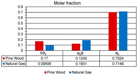
Figure 6.
Mole fraction of CO2, H2, and N2 for pine wood and natural gas under stoichiometric conditions.
The adiabatic flame temperatures (Taf), under stoichiometric combustion reactions (Table 2), were 2800 K for pine wood and 2326 K for natural gas. Although pine wood exhibits a higher adiabatic flame temperature, its use contributes to deforestation and environmental degradation, whereas natural gas results in lower emissions of pollutants and poses a reduced impact on ecosystems.
4.3. Comparison Between Experimental Temperature Obtained with Pine Wood and CFD-Predicted Temperature Using Natural Gas
CFD simulation using natural gas was carried out as a hypothetical case to investigate the potential benefits of fuel switching. As shown in Figure 6, the use of natural gas could achieve a theoretical CO2 reduction of up to 44.08%. Thus, Figure 7 shows a comparison between the average temperatures of hot gases measured by 52 K type thermocouples (Figure 4b) and those predicted by the TC model using natural gas. It can be observed that the increment in the temperature of the hot gases of the TC Model over time is very similar to the temperature increment in the hot gases of the two tests; only a few points had increments in temperatures, for example, at 2 h and 5 h, or decrements in temperature, for example, at 11 h and 14 h, both related to the experimental temperature values. These oscillations of temperature are attributed to the behavior of the fluid flow inside the combustion chamber of the brick kiln and inside the channels of the brick kiln, as it will be shown in Section 4.4. The increased temperatures of the hot gases, ΔT, inside the kiln were obtained from ΔT = Tfinal − Tinitial, where Tfinal is the temperature of the hot gases inside the brick kiln at the time of 14 h and Tinitial is the initial value of the temperature of the system at the time of 0 h. The increased temperature values were 536.2 K, 554.3 K, and 459.3 K for test 1, test 2, and TC Model, respectively.
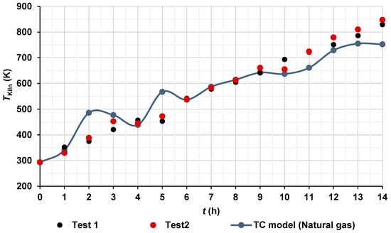
Figure 7.
Hot gas temperatures inside the brick kiln over time.
It is worth mentioning that the limitations of validating a natural gas model with pine wood data exist because, to date, natural gas has not been widely used in artisan brick kilns globally due to different challenges, such as fuel costs, limited distribution infrastructure in rural areas, the informal nature of the brick yards, and a lack of regulations (artisans prioritize lower operating costs, even at the cost of higher polluting emissions) and financial incentives by the governments. Additionally, many artisanal kilns are not technically adapted for natural gas combustion and artisans are not technically trained, and the transition would require significant investment in research, equipment, and training. Therefore, only a comparison is presented in Figure 7.
4.4. CFD Temperature and Velocity Distributions in the Interior of the Brick Kiln
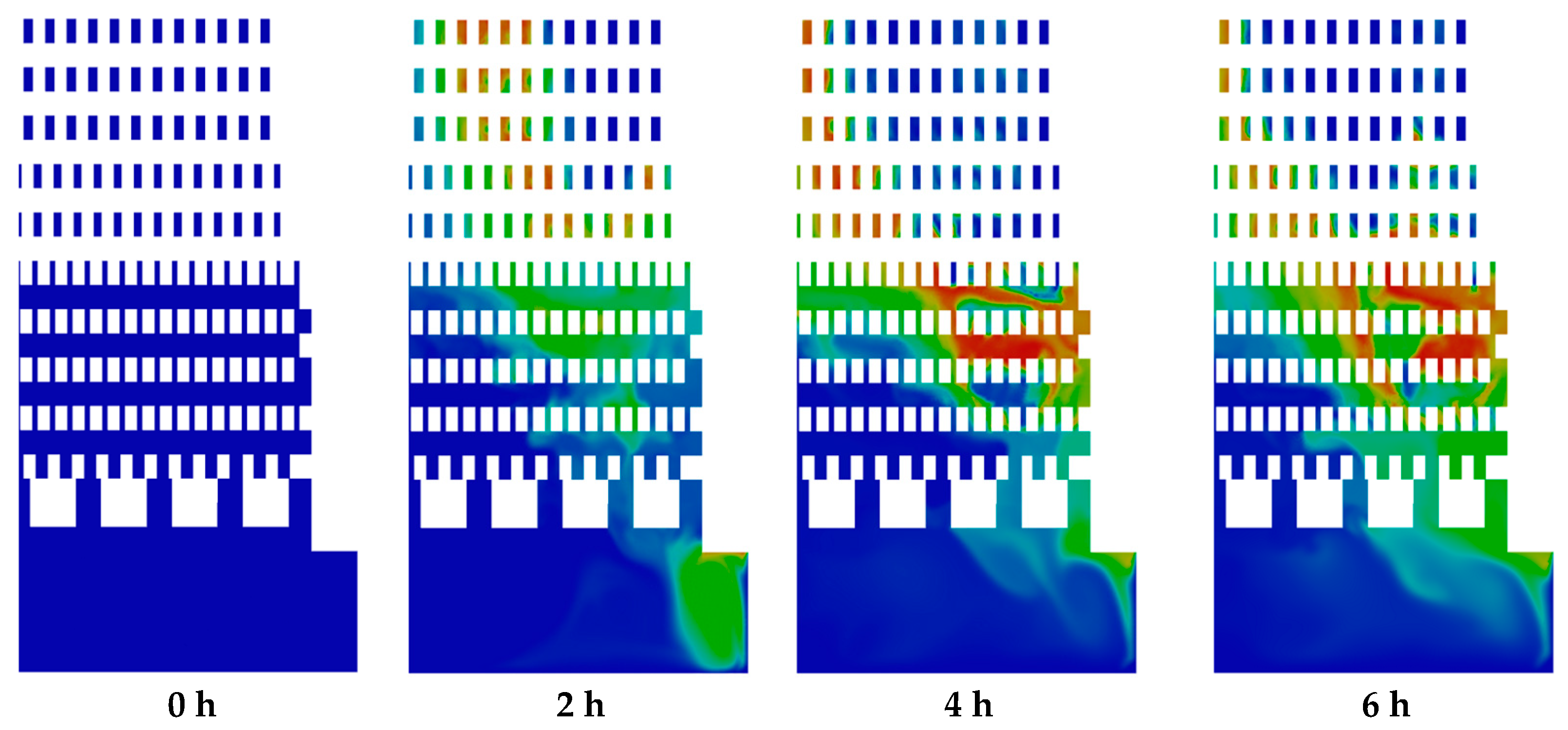
Figure 8 and Figure 9 show the numerical temperature contours and velocity vector fields of the hot gases over the course of the firing process for the burning of natural gas (from 0 to 14 h). These distributions are presented on a plane located at the midsection of the kiln’s inlet. Figure 8 illustrates the evolution of temperature contours over time. At the initial time (t = 0 h), the entire domain within the brick kiln exhibited a uniform temperature of 293.15 K, and the hot gas velocity was zero. By the end of the firing process (t = 14 h), the average temperature of the hot gases within the kiln had risen to 752.45 K, representing a temperature increase of ΔT = 459.3 K. The local maximum temperature was 1275 K, located in the combustion chamber and the middle section of the zigzag channels, influenced by the combustion process.
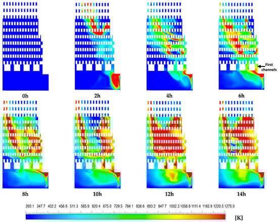
Figure 8.
Contours of hot gas temperature [K].
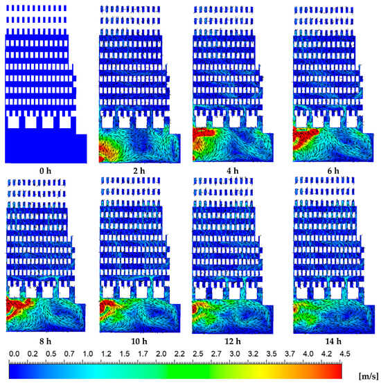
Figure 9.
Velocity vector with velocity contours of the hot gases over time.
The hot gas temperature distribution within the brick kiln exhibited significant inhomogeneity, especially within the combustion chamber and the zigzag channels formed by the layered brick arrangement (Figure 1). A significant temperature increase was observed along the vertical direction of both the left and right sides of each contour within the zigzag zone from 8 to 14 h, while comparatively lower temperatures were noted on the left side of the zigzag zone from 2 h to 4 h and on the left side of the combustion chamber from 2 h to 14 h. These temperature differences are mainly caused by preferential flow paths of the hot gases, induced by the kiln’s geometric design (Figure 9). The resulting non-uniform thermal distribution may lead to reduced compressive strength in bricks exposed to lower temperatures. Additionally, consistently lower temperatures were observed near the upper region of each contour (corresponding to the kiln’s outlet), which could potentially compromise the compressive strength of the bricks. This issue is particularly relevant for the construction sector, where achieving sufficient compressive strength is critical to meet established quality standards (Dhote et al. [7], Beyene et al. [20], Alonso-Romero et al. [18], Vasić et al. [24], and Riaz et al. [25]).
Figure 9 presents the velocity contours at the same plane where the temperature distributions were previously shown. Peak flow velocities of up to 4.5 m/s were observed within the combustion chamber, whereas significantly lower velocities were observed in the zigzag channels of the brick kiln. The interaction between the incoming air–fuel mixture and the combustion process led to the formation of vortical structures inside the combustion chamber. Notably, during the initial two hours of the firing process, vortex formation was concentrated near the kiln’s door, at the inlet region. As the firing process advanced, the vortices within the combustion chamber gradually shifted toward the left side, altering the internal thermal and flow behavior of the kiln. During the initial two hours, high-velocity hot gases predominantly ascended through the upper channels of the combustion chamber, particularly toward the right-hand side and near the kiln’s entrance. Over time, flow velocities within these channels increased; however, the distribution of velocity remained uneven due to the persistent influence of vortical structures generated in the combustion zone. This irregular flow pattern led to a non-uniform velocity field throughout the zigzag channels, closely aligning with the observed temperature gradients. Such non-uniformities in both velocity and temperature may adversely impact on the firing consistency and, consequently, the overall quality of the bricks produced.
4.5. Results of Species
Figure 10 shows CO2 emission. It can be observed that the regions of mole fraction of CO2 increased in the zigzag channels and combustion chambers over time due to the oxidation of methane by the combustion process. Moreover, the regions of CO2 are correlated with the regions of the temperature (Figure 8). Similar distribution of mole fraction was observed for H2O and CO emissions. The highest local values of mole fractions were 0.097 for CO2, 0.19 for H2O, and 0.028 for CO emissions.
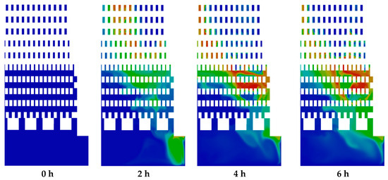
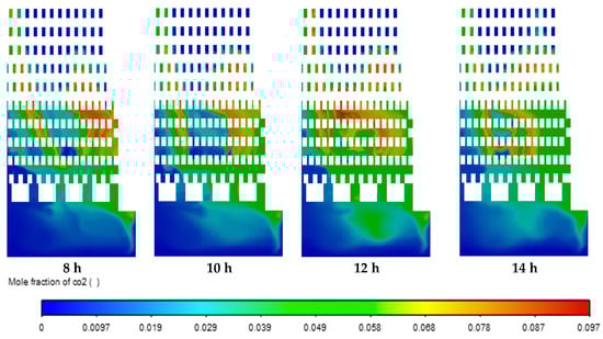
Figure 10.
Contours of mole fraction of CO2.
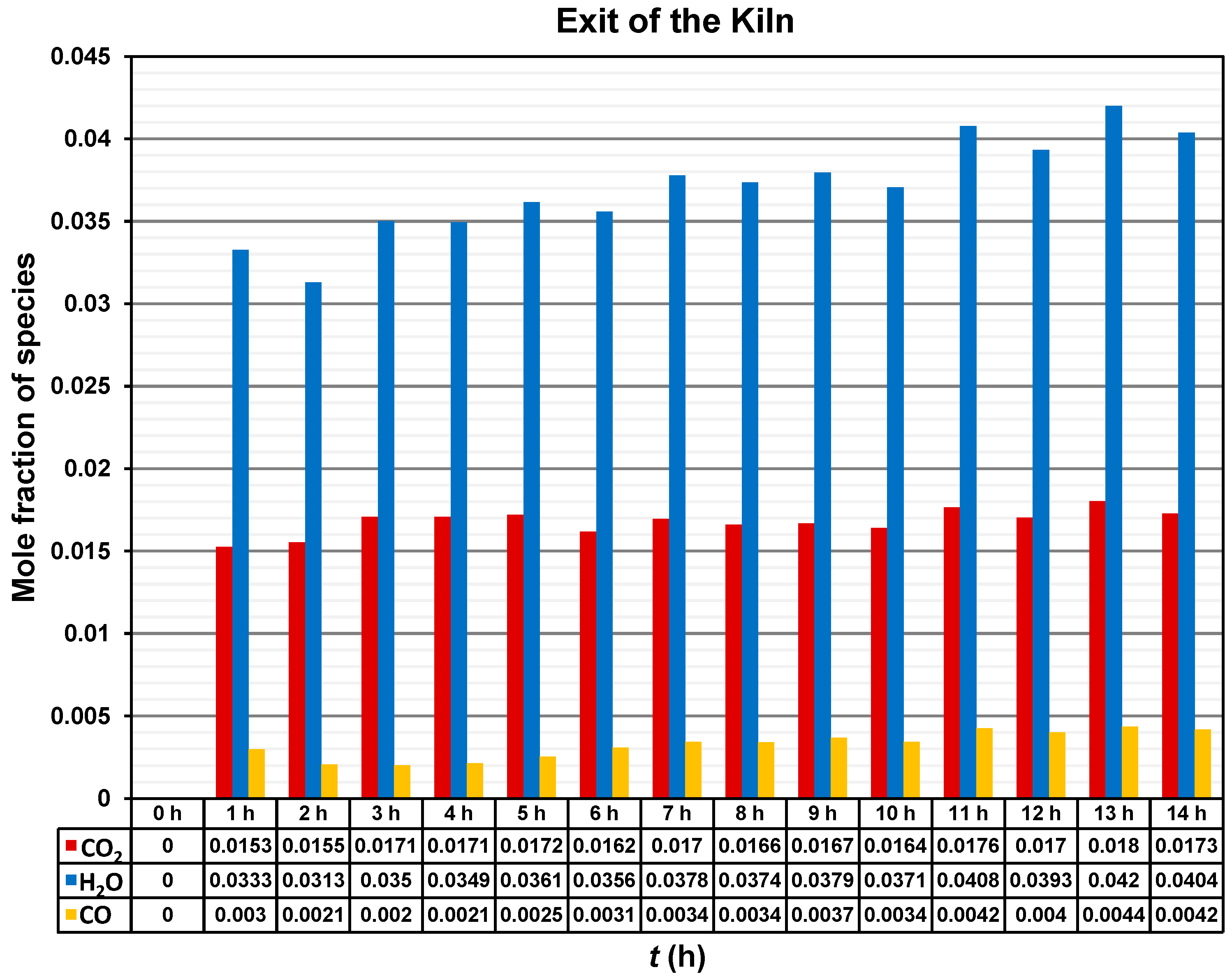
Figure 11 shows mole fraction of the species CO2, H2O, and CO at the outlet of the brick kiln throughout the 14 h of operation of the firing process. The mole fraction of the CO2 increased to a value around 0.015 during the first two hours, and then it oscillates between 0.016 and 0.017 for the following time. The highest value of mole fraction of CO2 of around 0.018 was recorded at 13 h.
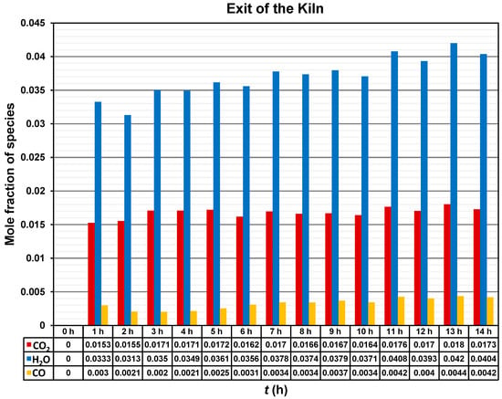
Figure 11.
Mole fraction of CO2, H2O, and CO emissions at the outlet of the brick kiln.
A tendency for the mole fraction of H2O to increase over time can be observed. However, the mole fraction of H2O also fluctuates between 0.031 and 0.042. The highest value of mole fraction of H2O of around 0.042 was recorded at 13 h.
Finally, the mole fraction of CO exhibited the lowest values among the analyzed species, ranging from approximately 0.002 to 0.004 over time. Nevertheless, the presence of CO indicates incomplete combustion.
4.6. Results of the CFD Temperature of the Hot Gases Under Stoichiometric, Fuel-Rich, and Excess Air Conditions
The temperatures of the hot gases were obtained and compared under three different conditions: stoichiometric condition (AF ratio of 17.19), fuel-rich or deficiency of air condition (AF ratio of 15, 12.74% deficiency of air), and excess air condition (AF ratio of 31.2, 81.5% excess air). At the end of the firing process, the maximum temperatures of the hot gases under stoichiometric, fuel-rich, and excess air conditions were 953.25 K, 913.37 K, and 752.45 K, respectively (Figure 12). This behavior is consistent due to the fact that, under stoichiometric conditions, the AF ratio provides just enough oxygen for complete combustion, obtaining the highest temperatures. In the fuel-rich condition, there is less oxygen available (in this case, near the stoichiometric conditions), which results in incomplete combustion, obtaining a higher temperature than in the case of excess of air, and a slightly lower temperature than in the stoichiometric condition. In the excess air condition, the additional air acts as a thermal diluent, absorbing part of the heat released by the combustion, obtaining a decrease in temperature. The presence of excess nitrogen and oxygen that do not participate directly in combustion contributes to decrease the temperature.
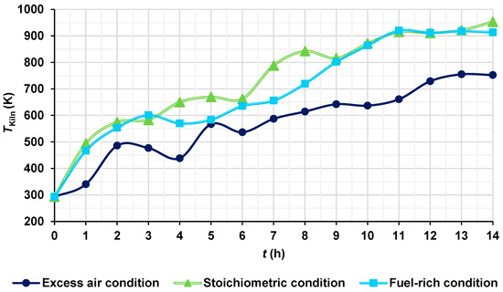
Figure 12.
Temperatures of the hot gases for different conditions.
4.7. NOx Emission Results
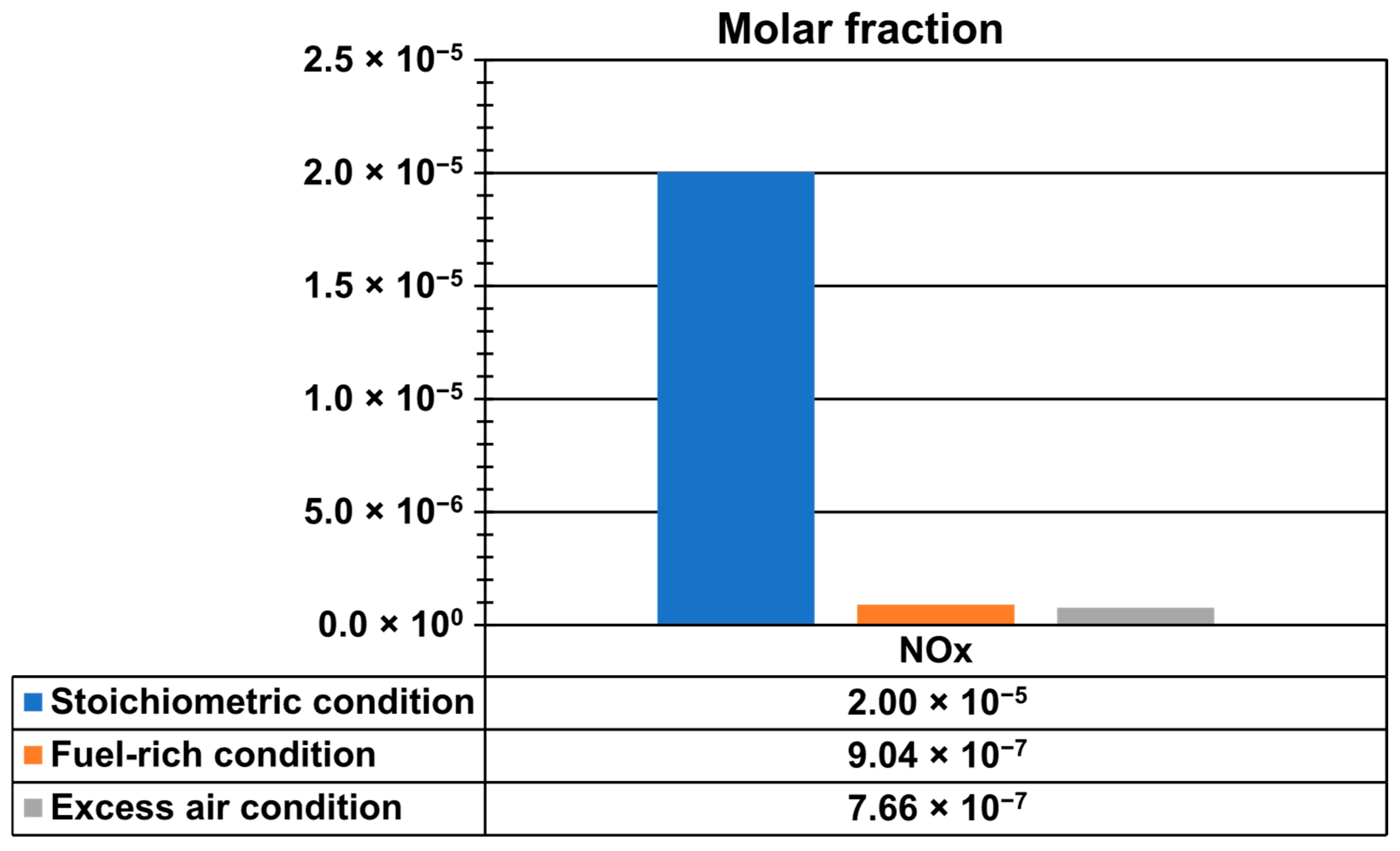
Figure 13 shows NOx emissions at the outlet of the kiln and at the end of the firing process, where the highest temperatures of hot gases occurred, to capture the maximum values. Emissions were analyzed under three different conditions: stoichiometric (AF ratio 17.19), fuel-rich or deficiency of air (AF ratio of 15, 12.74% deficiency of air), and excess-air (AF ratio of 31.2, 81.5% excess air). The maximum NOx mole fractions were 2.0049279 × 10⁻⁵ for stoichiometric conditions, 9.0398022 × 10⁻⁷ for fuel-rich conditions, and 7.659239 × 10⁻⁷ for excess-air conditions. These results indicate that the highest NOx emissions occurred under stoichiometric combustion, while significantly lower values were observed in both fuel-rich and excess air conditions.

Figure 13.
Mole fraction of NOx emissions.
Finally, it is worth mentioning that the transition from traditional fuels to natural gas in brick kilns faces notable economic and practical challenges. In the case of economic challenges, the high upfront cost of converting kiln infrastructure —such as installing gas burners, pipelines, and safety systems— poses a significant investment, especially for small-scale artisanal producers. Additionally, the ongoing cost of natural gas can be higher compared to locally available fuels, such as dung, coconut shells, charcoal, wood, sawdust, waste-derived fuels, or hazardous materials like unusable tires, engine oil, plastics, electronic waste, and among others (Berumen-Rodríguez et al. [4] and INECC [5]), making it less attractive in regions where profit margins are already thin. In the case of practical challenges, artisanal kilns are not designed to operate with natural gas, requiring extensive retrofitting or a complete redesign. Moreover, the lack of natural gas distribution infrastructure in rural and peri-urban areas —where most brick kilns are located—significantly limits its access. Moreover, the informal nature of the industry also creates challenges in regulation, financing, and training, all of which are necessary for a successful and sustainable fuel switch. As a result, without targeted government support or incentives, the widespread adoption of natural gas in the brick sector remains difficult.
5. Conclusions
This work presented experimental measurements of transient hot gas temperatures using pine wood as fuel, along with the compressive strength of the bricks. Additionally, a transient combustion model using natural gas as fuel was used with the aim to demonstrate how a cleaner fuel source could offer significant benefits for the artisanal brick industry. Theoretical emissions and adiabatic flame temperatures were compared for the stoichiometric combustion of pine wood and natural gas. Experimental and numerical hot gas temperatures were analyzed over the entire 14-h firing process. Furthermore, CFD numerical simulations were carried out under three different combustion conditions, stoichiometric (AF ratio = 17.19), fuel-rich (AF ratio = 15, corresponding to a 12.74% air deficiency), and excess air (AF ratio = 31.2, equivalent to 81.5% excess air), to obtain transient hot gas temperatures and NOx emissions.
- Stoichiometric combustion of pine wood and natural gas demonstrated that CO2 emissions could be reduced by 44.08% when using natural gas in brick kilns, representing a cleaner and sustainable alternative.
- Based on the results of hot gas temperatures and velocity fields, preferential flow pathways of hot gases were identified, primarily caused by vortex formation in the combustion chamber and upper channels. As a result, the transient hot gas temperatures and velocity distribution inside the kiln were uneven, likely contributing to variations in the final compressive strength of the bricks. These inconsistencies in heat distribution affected the quality of firing, leading to firing efficiencies of 50.1% for test 1 and 45.8% for test 2, according to the Mexican standard. In contrast, the thermal efficiency of the process was 24.4%.
- The transient combustion model (TC) model presented in this study may contribute to the development of strategies aimed at achieving more uniform temperature and velocity distributions by optimizing flow channel configurations. This, in turn, could enhance the quality of fired bricks for construction applications. Additionally, adjusting operational parameters, such as the mass flow rates of fuel and air, may help to reduce CO2 emissions.
- The presence of CO mole fractions at the kiln outlet suggests that the transient combustion process can be further improved by optimizing air–fuel ratios, enhancing the overall combustion process during the firing stage.
- Stoichiometric combustion conditions resulted in higher hot gas temperatures and increased NOx emissions compared to both fuel-rich and excess air conditions.
Finally, CFD numerical results provide valuable insights into the potential benefits of fuel switching in the brickyard industry. The transient combustion (TC) model presented in this work opens the door for improving thermal–hydraulic performance and emissions control, and future kiln designs. Future work could be focused on further reducing the environmental impact by precisely adjusting combustion conditions to reduce fuel consumption, optimizing the spacing and arrangement of bricks to enhance flow channel configuration, and to promote more homogeneous temperature distribution, thereby improving energy efficiency and decreasing pollutant emissions from the brick manufacturing process.
Author Contributions
S.A.-R.: Writing—review and editing, Writing—original draft, Validation, Supervision, Resources, Methodology, Investigation, Funding acquisition, Formal analysis, Conceptualization. J.A.A.-A.: Writing—review and editing, Writing—original draft, Validation, Software, Methodology, Investigation, Funding acquisition, Formal analysis, Conceptualization. J.E.F.-C.: Writing—review and editing, Writing—original draft, Validation, Methodology, Investigation, Data curation, Conceptualization. J.d.J.R.-M.: Writing—review and editing, Writing—original draft, Validation, Software, Investigation, Formal analysis, Conceptualization. O.A.L.-N.: Writing—review and editing, Writing—original draft, Validation, Software, Methodology, Investigation, Formal analysis. R.Z.-G.: Writing—review and editing, Writing—original draft, Validation, Software, Methodology, Investigation, Formal analysis. All authors have read and agreed to the published version of the manuscript.
Funding
This research was funded by Secretaría de Ciencia, Humanidades, Tecnología e Innovación (SECIHTI) grant numbers CONAHCYT-SENER-LABINNOVA-234633 and CVU-233122.
Data Availability Statement
The data are not publicly available due to privacy or ethical restrictions.
Acknowledgments
The authors gratefully acknowledge to the Secretaría de Ciencia, Humanidades, Tecnología e Innovación (SECIHTI), México, for the financial support of the project 234633 CONAHCYT-SENER LABINNOVA, for the postdoctoral fellowship of the CVU 233122, and for the financial support of the Sistema Nacional de Investigadores e Investigadoras (SNII) program. The authors greatly appreciate it.
Conflicts of Interest
The authors declare no conflicts of interest.
Nomenclature
The following nomenclature is used in this manuscript:
| c | Specific heat, J kg−1 K−1 |
| g | Gravity, m s−2 |
| h | Enthalpy, kJ kmol−1 |
| Sensible enthalpy at the standard reference state, kJ kmol−1 | |
| Enthalpy of formation at the standard reference state, kJ kmol−1 | |
| N | Number of moles, kmol |
| M | Molar mass, kg kmol−1 |
| Mass flow rate, kg s−1 | |
| P | Pressure, Pa |
| T | Temperature, K |
| t | Time, s |
| u, v, w | Velocity, m s−1 |
| Z | Elemental mass fraction |
| Greek letters | |
| λ | Thermal conductivity, W m−1 K−1 |
| μ | Dynamic viscosity, Pa s |
| ρ | Density, kg m−3 |
| Subscripts | |
| p | Products |
| r | Reactants |
| i | Element |
| ox | Oxidizer stream |
| fuel | Fuel stream |
References
- Refaey, H.A.; Alharthi, M.A.; Salem, M.R.; Abdel-Aziz, A.A.; Abdelrahman, H.E.; Karali, M.A. Numerical investigations of convective heat transfer for lattice settings in brick tunnel Kiln: CFD simulation with experimental validation. Therm. Sci. Eng. Prog. 2021, 24, 100934. [Google Scholar] [CrossRef]
- Tu, Y.; Su, K.; Liu, H.; Wang, Z.; Xie, Y.; Zheng, C.; Li, W. MILD combustion of natural gas using low preheating temperature air in an industrial furnace. Fuel Process. Technol. 2017, 156, 72–81. [Google Scholar] [CrossRef]
- Hussnain, S.A.; Farooq, M.; Amjad, M.; Riaz, F.; Tahir, Z.U.R.; Sultan, M.; Hussain, I.; Shakir, M.A.; Qyyum, M.A.; Han, N.; et al. Thermal Analysis and Energy Efficiency Improvements in Tunnel Kiln for Sustainable Environment. Processes 2021, 9, 1629. [Google Scholar] [CrossRef]
- Berumen-Rodríguez, A.A.; Pérez-Vázquez, F.J.; Díaz-Barriga, F.; Márquez-Mireles, L.E.; Flores-Ramírez, R. Revisión del impacto del sector ladrillero sobre el ambiente y la salud humana en México. Salud Pública México 2021, 63, 100–108. [Google Scholar] [CrossRef]
- INECC. Regional Level Market Analysis of the Construction Sector and Pilot Project based on a Public Policy Portfolio in Order to Reduce SLCP of Traditional Brickyards in Mexico. Final Report 2016, April 2025. National Institute of Ecology and Climate Change (INECC), Mexico. Available online: https://www.gob.mx/cms/uploads/attachment/file/252837/Final_report_pub_final_290817.pdf (accessed on 1 May 2025).
- Ahmad, H.R.; Farooqi, Z.U.R.; Sabir, M.; Sardar, M.F. Brick Kilns: Types, Emissions, Environmental Impacts, and Their Remedial Measures; Springer Nature: Cham, Switzerland, 2022; Chapter 52; Volume 2, pp. 945–958. ISBN 978-3-030-73942-3. [Google Scholar] [CrossRef]
- Dhote, L.; Chavan, D.; Pandey, R.; Manwatkar, P.; Middey, A.; Kumar, S. Experimental investigation on utilization of distillery sludge mixed with coal as a Low-grade fuel in brick kiln industry and product analysis. Fuel 2022, 324, 124467. [Google Scholar] [CrossRef]
- Khanoranga; Khalid, S. Phytomonitoring of air pollution around brick kilns in Balochistan province Pakistan through air pollution index and metal accumulation index. J. Clean. Prod. 2019, 229, 727–738. [Google Scholar] [CrossRef]
- Farhad, S.A.H.; Begum, K.; Parveen, Z.; Hossain, M.F. Assessment of macro and micro nutrients around brick kilns agricultural environment. Inf. Progress. Agric. 2016, 3, 61–68. [Google Scholar] [CrossRef]
- Kamal, A.; Naseem Malik, R.; Martellini, T.; Cincinelli, A. Cancer risk evaluation of brick kiln workers exposed to dust bound PAHs in Punjab province (Pakistan). Sci. Total Environ. 2014, 493, 562–570. [Google Scholar] [CrossRef] [PubMed]
- Brooks, N.; Biswas, D.; Hossin, R.; Yu, A.; Saha, S.; Saha, S.; Saha, S.K.; Luby, S.P. Health consequences of small-scale industrial pollution: Evidence from the brick sector in Bangladesh. World Dev. 2023, 170, 106318. [Google Scholar] [CrossRef]
- Haque, S.E.; Shahriar, M.M.; Nahar, N.; Haque, M.S. Impact of brick kiln emissions on soil quality: A case study of Ashulia, brick kiln cluster, Bangladesh. Environ. Chall. 2022, 9, 100640. [Google Scholar] [CrossRef]
- Refaey, H.A.; Awadh, A.B.; Abdel-Aziz, A.A.; Abdelrahman, H.E.; El-Ghany, H.A.A.; Karali, M.A.; Al-Dosoky, M.W. Transient thermal behavior in brick tunnel kiln with guide vanes: Experimental study. Case Stud. Therm. Eng. 2022, 33, 101959. [Google Scholar] [CrossRef]
- Refaey, H.A.; Abdel-Aziz, A.A.; Salem, M.R.; Abdelrahman, H.E.; Al-Dosoky, M.W. Thermal performance augmentation in the cooling zone of brick tunnel kiln with two types of guide vanes. Int. J. Therm. Sci. 2018, 130, 264–277. [Google Scholar] [CrossRef]
- Refaey, H.A.; Abdel-Aziz, A.A.; Ali, R.K.; Abdelrahman, H.E.; Salem, M.R. Augmentation of convective heat transfer in the cooling zone of brick tunnel kiln using guide vanes: An experimental study. Int. J. Therm. Sci. 2017, 122, 172–185. [Google Scholar] [CrossRef]
- Refaey, H.A.; Alharthi, M.A.; Abdel-Aziz, A.A.; Elattar, H.F.; Almohammadi, B.A.; Abdelrahman, H.E.; Karali, M.A.; Attia, E.A.; Al-Dosoky, M.W. Fluid Flow Characteristics for Four Lattice Settings in Brick Tunnel Kiln: CFD Simulations. Buildings 2023, 13, 733. [Google Scholar] [CrossRef]
- Al-Hasnawi, A.G.T.; Refaey, H.A.; Redemann, T.; Attalla, M.; Specht, E. Computational Fluid Dynamics Simulation of Flow Mixing in Tunnel Kilns by Air Side Injection. J. Thermal Sci. Eng. Appl. 2018, 10, 031007. [Google Scholar] [CrossRef]
- Alonso-Romero, S.; Alfaro-Ayala, J.A.; Frias-Chimal, J.E.; Ramírez-Minguela, J.J.; López-Núñez, O.A. Transient thermal analysis of a kiln using different numerical approaches by means of CFD. Case Stud. Therm. Eng. 2024, 64, 105441. [Google Scholar] [CrossRef]
- Ngom, M.; Thiam, A.; Balhamri, A.; Sambou, V.; Raffak, T.; Refaey, H.A. Transient study during clay bricks cooking in the traditional kiln; CFD numerical study. Case Stud. Therm. Eng. 2021, 28, 101672. [Google Scholar] [CrossRef]
- Beyene, A.; Ramayya, V.; Shunki, G. CFD Simulation of Biogas Fired Clay Brick Kiln. Am. Am. J. Eng. Appl. Sci. 2018, 11, 1045–1061. [Google Scholar] [CrossRef]
- Arvanitidis, A.L.; Kostoglou, M.; Georgiadis, M.C. Optimizing industrial tunnel kiln operations for ceramic roof tile production: A bi-objective approach. Chem. Eng. Sci. 2024, 295, 120223. [Google Scholar] [CrossRef]
- Arvanitidis, A.L.; Kostoglou, M.; Georgiadis, M.C. Modeling, optimization and control of a ceramic tunnel kiln for consistent product quality under changing production demands. Comput. Chem. Eng. 2024, 189, 108812. [Google Scholar] [CrossRef]
- Cansee, S.; Pattiya, A. Application of solid media for enhancing the temperature distribution within a downdraft kiln during clay brick firing. Eng. Appl. Sci. Res. 2023, 50, 405–412. [Google Scholar] [CrossRef]
- Vasić, M.V.; Pezo, L.; Zdravković, J.D.; Bačkalić, Z.; Radojević, Z. The study of thermal behavior of montmorillonite and hydromica brick clays in predicting tunnel kiln firing curve. Constr. Build. Mater. 2017, 150, 872–879. [Google Scholar] [CrossRef]
- Riaz, M.H.; Khitab, A.; Ahmed, S. Evaluation of sustainable clay bricks incorporating Brick Kiln Dust. J. Build. Eng. 2019, 24, 100725. [Google Scholar] [CrossRef]
- Kazmi, S.M.S.; Abbas, S.; Saleem, M.A.; Munir, M.J.; Khitab, A. Manufacturing of sustainable clay bricks: Utilization of waste sugarcane bagasse and rice husk ashes. Constr. Build. Mater. 2016, 120, 29–41. [Google Scholar] [CrossRef]
- Gencel, O. Characteristics of fired clay bricks with pumice additive. Energy Build. 2015, 102, 217–224. [Google Scholar] [CrossRef]
- Launder, B.E.; Spalding, D.B. Lectures in Mathematical Models of Turbulence; Academic Press: London, UK, 1972. [Google Scholar]
- Alfaro-Ayala, J.A.; Gallegos-Muñoz, A.; Manuel Riesco-Ávila, J.; Flores-López, M.; Campos-Amezcua, A.; Germán Mani-González, A. Analysis of the flow in the combustor-transition piece considering the variation in the fuel composition. J. Therm. Sci. Eng. Appl. 2011, 3, 021003. [Google Scholar] [CrossRef]
- Alfaro-Ayala, J.A.; Gallegos-Muñoz, A.; Uribe-Ramírez, A.R.; Belman-Flores, J.M. Use of bioethanol in a gas turbine combustor. Appl. Therm. Eng. 2013, 61, 481–490. [Google Scholar] [CrossRef]
- Patankar, S.V. Numerical Heat Transfer and Fluid Flow; Hemisphere Publishing Corporation: Washington, DC, USA, 1980. [Google Scholar]
- Milićević, A.; Belošević, S.; Žarković, M.; Tomanović, I.; Crnomarković, N.; Stojanović, A.; Stupar, G.; Deng, L.; Che, D. Effects of biomass particles size and shape on combustion process in the swirl-stabilized burner reactor: CFD and machine learning approach. Biomass Bioenergy 2023, 174, 106817. [Google Scholar] [CrossRef]
- Backreedy, R.L.; Fletcher, J.; Jones, L.; Ma, M.; Pourkashanian, A. Williams. Co-firing pulverised coal and biomass: A modeling approach. Proc. Combust. Inst. 2005, 30, 2955–2964. [Google Scholar] [CrossRef]
- Çengel, Y.A.; Ghajar, A.J. Heat and Mass Transfer Fundamentals and Applications, 5th ed.; McGraw-Hill Companies: New York, NY, USA, 2015; ISBN 978-0-07-339818-1. [Google Scholar]
- Karaman, S.; Ersahin, S.; Gunal, H. Firing temperature and firing time influence on mechanical and physical properties of clay bricks. J. Sci. Ind. Res. 2006, 65, 153–159. [Google Scholar]


Disclaimer/Publisher’s Note: The statements, opinions and data contained in all publications are solely those of the individual author(s) and contributor(s) and not of MDPI and/or the editor(s). MDPI and/or the editor(s) disclaim responsibility for any injury to people or property resulting from any ideas, methods, instructions or products referred to in the content. |
© 2025 by the authors. Licensee MDPI, Basel, Switzerland. This article is an open access article distributed under the terms and conditions of the Creative Commons Attribution (CC BY) license (https://creativecommons.org/licenses/by/4.0/).