1. Introduction
The processes of oil and gas development and maintenance require substantial energy consumption. Insufficient maintenance of oil and gas wells will significantly increase the energy consumption required for oil and gas recovery, increase the recovery costs, and directly affect the economic benefits of oil and gas development. Well washing is an important means of oil and gas field maintenance. Good well washing effects can reduce reservoir damage caused by mud migration and restore reservoir porosity and permeability. The energy consumption and efficiency of well cleaning equipment directly affect the final well cleaning effect. Traditional well cleaning equipment relies on a water jet to wash the wellbore, which has low cleaning efficiency and small water flow coverage, resulting in a large amount of energy waste and greatly increasing the maintenance costs of oil and gas wells.
With the development of global oil and gas resources extending to deep, ultra-deep, and unconventional fields, deep drilling and horizontal well technology have become a core means of overcoming geological conditions and improving single-well productivity. This kind of complex well type significantly improves oil and gas recovery by extending the contact area between the wellbore and the reservoir, especially in the development of unconventional resources, such as shale oil and gas, tight oil and gas, and so on [
1,
2,
3,
4]. The Kola ultra-deep well is the drilling well with the largest vertical depth of 12,262 m, and the oil and gas production well with the largest vertical depth is the Shendituo-1 well, which reaches 10,910 m below the Earth’s surface. While directional wells are usually smaller in vertical depth, some horizontal wells can be extended to a reservoir depth of 7000 m underground [
5]. This large depth results in extreme working conditions: the temperature at 8 km underground can exceed 300 °C, and the formation pressure at 10 km underground can be as high as 150 MPa. Complex formation distribution also results in differences in the trajectory and wellbore structure in different sections of a wellbore. Meanwhile, the existence of long horizontal intervals in deep and horizontal wells and the need for wellbore integrity maintenance under complex geological conditions where the wellbore trajectory is located pose severe challenges to drilling, completion, and production maintenance technology. The oil and gas development industry is currently improving drilling success rates and wellbore maintenance capabilities. How the life cycle management efficiency of complex well types can be improved has become the core question for ensuring the economic development of unconventional oil and gas resources [
6].
Deep drilling and horizontal wells play an important role in oil and gas resource development; however, they face many difficulties in maintenance. Due to the large length and depth of wells, their complicated downhole environment, high temperatures, and high pressures, high requirements are put forward for wellbore integrity, casing, and maintenance tool durability [
7,
8,
9]. At the same time, the high costs and the long period of the maintenance cycle for deep wells have a direct impact on the economic benefits of oil and gas fields [
10]. Horizontal wells also face many challenges in the maintenance process due to their special wellbore trajectory. The horizontal well trajectory is irregular, and the dogleg degree is large, which further increases the difficulty of maintenance operations. Due to their long horizontal interval, sand production and wax deposition are more likely to occur in horizontal wells during production [
11,
12,
13,
14,
15]. The wide range of sand production in horizontal wells requires more frequent maintenance operations, such as well washing and wax cleaning, to be carried out.
Manual control and semi-automatic monitoring modes are widely adopted in existing well washing equipment, and equipment control needs to be implemented through multi-level command transmission, resulting in response lag and operation cycle extension [
16]. In traditional well flushing operations, the switching of the well washing mode needs to lead to the shutdown of all the equipment and the restarting of the device; then, it should be returned to the oil and gas well after switching the well washing mode on the surface, which cannot be adjusted immediately according to the change in downhole working conditions and requirements, which not only increases the labor costs but also limits further improvements in operation efficiency. Limited by the automation level of the equipment, well-flushing operations need to be implemented in stages. A single well cycle can last as long as 5–7 days, and the frequent tripping of the tubing string further aggravates the risk of wellbore damage. Traditional mechanical scouring and chemical plugging removal technology is significantly attenuated in the environment of high temperature and high pressure in deep wells. The multiphase flow characteristics of long horizontal sections of horizontal wells lead to uneven distribution of cleaning medium, and the plugging removal rate in the near-well zone is less than 60%. In addition, existing well washing methods are highly dependent on a single chemical solvent or mechanical washing technology and lack targeted solutions in the face of compound pollution, resulting in large fluctuations in operating effects, repeated well washing for some wells, and non-production time accounting for more than 30% [
17]. These technical problems not only significantly restrict the stable development of single-well productivity, but also directly lead to a substantial increase in non-production time, which becomes a common problem restricting the efficient development of complex oil and gas reservoirs. Breaking through the bottleneck of deep horizontal well maintenance technology and building a multi-method, automatic, and adaptable wellbore life cycle management technology system have become the core directions urgently requiring attention of current development and maintenance technology research.
In order to solve the above problems, researchers have studied and designed the sand removal mechanism and cleaning equipment of deep and horizontal wells. Liu et al. (2022) studied cleaning tools with different structures by using a turbulence model and a computational fluid dynamics method [
18]. The results show that the annular flow field of the cleaning tool can be divided into four velocity distribution areas, where the maximum velocity appears in the slow drop area near the outer wall, and it is more favorable to increase the nozzle with a specific configuration at the corresponding position for the velocity distribution of the well cleaning fluid. Bao et al. (2022) proposed a new method of double-string screen completion and jet washing for horizontal wells [
19]. Through continuous well washing operation of the inner-string jet washing system, the reservoir cleaning of a tight gas reservoir formation was performed, reservoir permeability was effectively improved, and the stimulation goal was achieved.
Table 1 lists the relevant patents for horizontal well washing device design at home and abroad, but currently, no researcher has studied the combination of hydraulic drive well washing and forward–reverse well washing mode-switching function, lacking systematic design, including both the washing device and the surface device. In this paper, an innovative automatic hydraulically driven well flushing device is proposed and designed to solve key problems such as a single-well flushing process, low efficiency, and insufficient adaptability to complex well types that are common in deep drilling operations. Through the multifunctional modular design concept, the device organically integrates core functions such as hydraulic drive, mode switching, automatic installation, and lifting to form a new well washing tool system with a compact structure, flexible operation, and superior performance. The device is designed to meet the requirements of fine well washing operation in a complex deep well environment more efficiently and reliably, so as to effectively improve operation efficiency and energy use efficiency.
2. Requirement Analysis and Method Design of Hydraulic Drive Well Cleaning Equipment
After long-term production operation, fine particles such as mud and sand migrate and accumulate, forming sand bridges and plugging wells, bringing extra resistance to fluid flow and reducing oil and gas production efficiency. The task of well cleaning equipment is to clean up the clogging existing in the inner wall of the wellbore and the environment near the bottom hole under extreme conditions such as high temperature, high pressure, and corrosion. The application of special types of wells, such as deep drilling and horizontal wells, puts forward additional requirements for the function and design of well washing devices [
20]. Conventional vertical wells have an angle of deviation of less than 3°, while directional wells utilize steering tools to obtain an angle of deviation greater than 3°. Directional wells with an angle of deviation greater than 85° and a horizontal displacement greater than 60 m are generally referred to as horizontal wells. In addition to the well deviation angle, another parameter with important influence is the displacement ratio of horizontal displacement to true vertical depth. The increase in the displacement ratio will increase the dogleg degree, improve equipment friction, cause equipment sticking, increase the difficulty of well washing equipment entering the wellbore, and put forward additional requirements for the design of downhole equipment such as well washers applied to directional wells [
21,
22]. The gravity effect in the horizontal interval also results in a significant difference between the movement of plugs in the horizontal interval and that in the vertical interval. Meanwhile, many horizontal wells are used for heavy-oil development, such as heavy-oil steam flooding technology, and the heavy-oil environment brings more complex plugs that are difficult to remove. According to the deposition law of blockages and the working environment of deep wells and horizontal wells, a kind of cleaning equipment should be developed, which can smoothly enter the bottom hole of deep and horizontal wells and effectively remove all kinds of blocking substances.
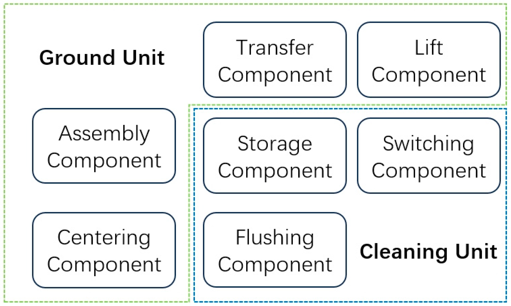
Well washing devices suitable for deep and horizontal wells should have the following characteristics: Firstly, the well cleaning device should have characteristics that allow it to withstand the downhole environment, and the length should not be too long. The mechanical structure with pressure resistance and corrosion resistance should be used mainly to reduce the use of electrical components and avoid equipment failure caused by damage to electrical components in the harsh downhole environment. Secondly, deep wells and horizontal wells have a long drilling distance, so the well washing device should have a certain storage capacity, reduce the number of lifting inspections, and shorten the operation cycle. Thirdly, a rotational flow stirring structure should be designed for horizontal intervals to prevent clogging, such as mud and sand, from accumulating downward under the effect of gravity, resulting in equipment obstruction or jamming and other failures. Fourthly, the device should have sufficient lifting capacity to guide the cleaning components and connected pipelines into deep wells and horizontal wells and effectively counteract the resistance formed by the curved section of the wellbore. Fifthly, the equipment should have a certain assembly capacity to ensure that cleaning parts and pipelines can be quickly combined to meet the needs of disassembly and extension, shorten assembly downtime, and improve cleaning efficiency. According to the above requirements, the module of the cleaning device can be divided into two parts: the ground unit and the cleaning unit (as shown in
Figure 1).
The working process of this device is as follows: When the device is in operation, firstly, the lifting component cooperates with the transfer component to lift and clamp the tail end of the fluid pipeline, and the assembly component combines the cleaning device to the tail end of the pipeline to complete equipment installation; then, the lifting component guides the cleaning unit into the wellbore. When the cleaning unit enters the preset position, the well flushing fluid is injected, and the cleaning unit is started under the driving of the flushing fluid. The pumping position of the flushing fluid determines the working mode of the cleaning unit: when the flushing fluid is pumped through the pipeline, the whole cleaning unit works in normal well washing mode, the switching component drives the storage component to work, and the flushing component operates in normal well flushing mode; when the flushing fluid is pumped from the wellbore annulus, the switching module closes the storage module, and the cleaning component performs a reverse washing operation.
3. Module Design of Hydraulic Drive Cleaning Equipment
In this chapter, SolidWorks 2020 software is utilized to design and assemble the required modules. According to the above analysis and design, the hydraulic drive cleaning equipment consists of five main modules, which are the hydraulic drive cutting–flushing module, the hydraulic well cleaning mode-switching module, the filter storage module, the chain lifting module, and the arm assembly module. The mechanical structure is designed according to the working environment of each module and the functional objectives to be achieved.
3.1. Hydraulic Drive Cutting–Flushing Module
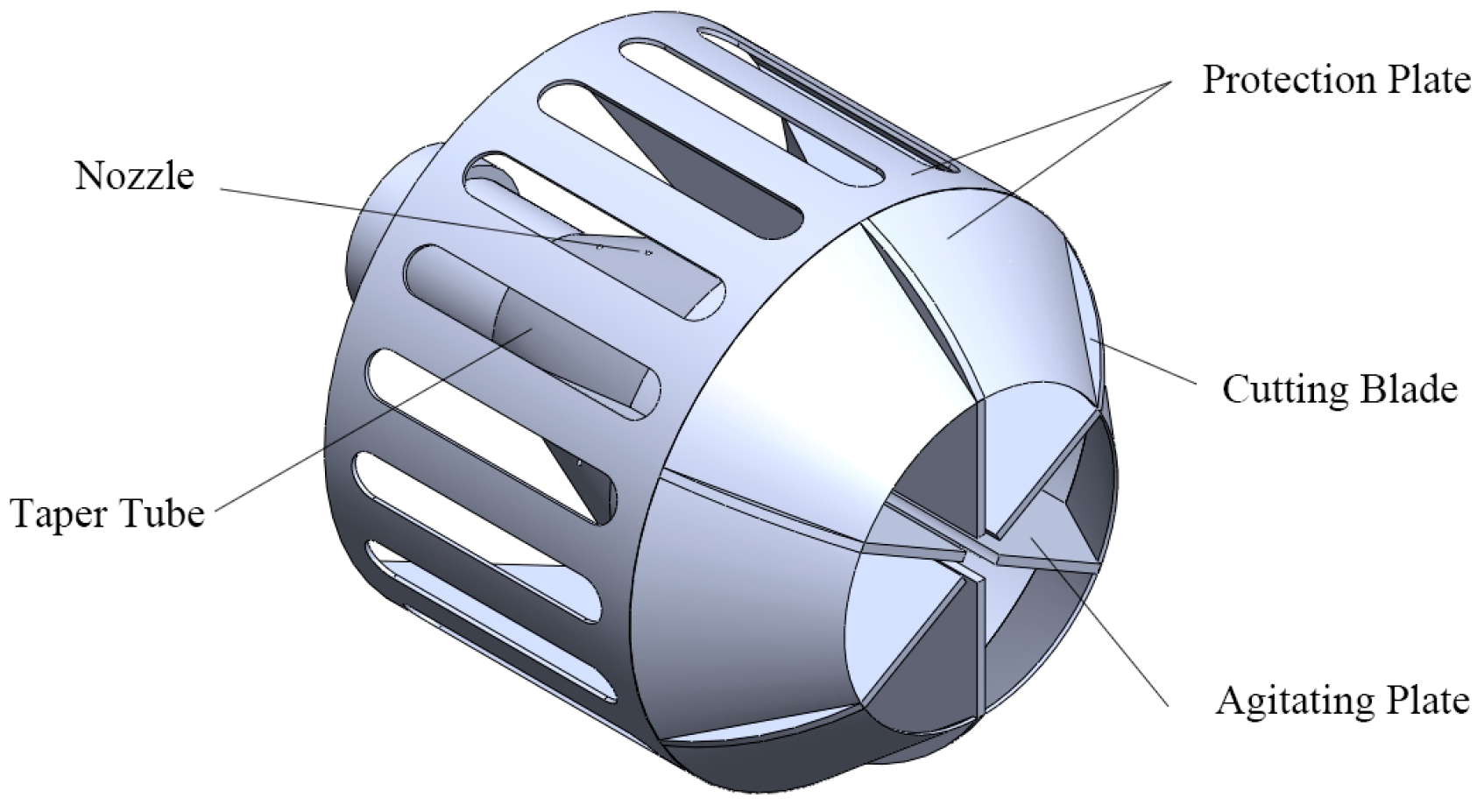
As shown in
Figure 2, the hydraulic drive cutting and flushing module is mainly composed of a taper pipe, nozzles, cutting blades, an agitating plate, and a protection plate. The main function of this module is to cut and flush the plugging material in the formation near the wellbore and in the wellbore. Its working principle is to continuously flush the plugging material by using the flushing action of a high-speed jet of well washing fluid and flush the cuttings to the rear of the flushing module to prevent repeated flushing. The whole module is driven to rotate by the recoil force of the high-pressure fluid flow, and the cutting blades are driven to cut the blockage. By converting part of the kinetic energy of the water flow into mechanical energy that drives the rotation of the module, the module cleans the wellbore with both a water jet and cutting blades, and the blockages are removed by the water flow.
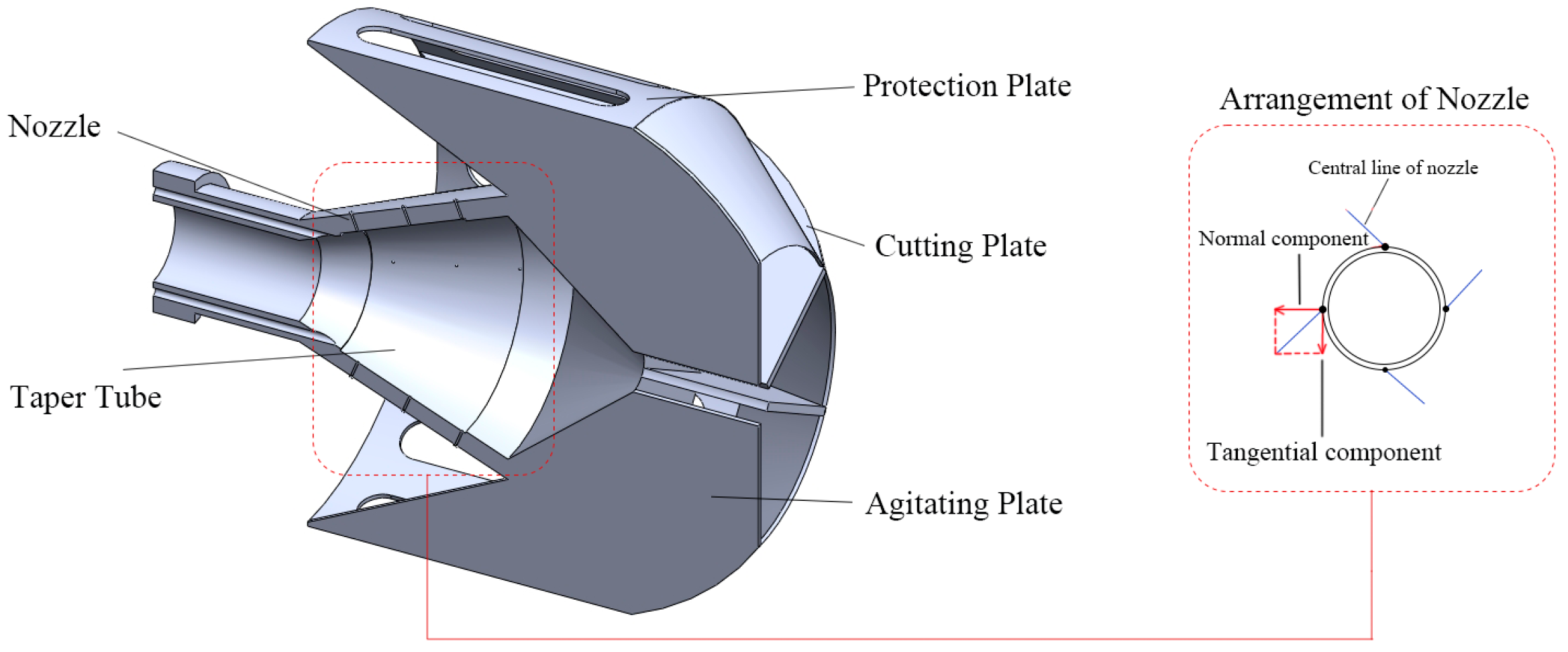
As shown in
Figure 3, except for the cutting blades, which are made of PDC material, all other parts are made with high-speed-steel material. The nozzles are installed obliquely on the surface of the conical pipe; these obliquely designed nozzles can generate inclined water flows once the flushing fluid is pumped into the device. When the fluid flows are pumped from these nozzles, according to Newton’s Third Law, they will also create reactions on the nozzles. This design divides the kinetic energy of the water flow into tangential and normal components. The normal kinetic energy of the water flow is used to clean the well wall and carry away mud and sand, and tangential kinetic energy is used to drive the module to rotate. The tangential component of the reaction force will drive the module to rotate as a whole. The PDC cutting blades are fixed at the front of the module, and when the module is driven to rotate, these cutting blades can cut hard particles such as cuttings and burrs, as well as viscous blockages that are difficult to completely clean by only hydraulic force, to restore the permeability of wellbore perforations. Hydraulic flushing and mechanical force cutting can thoroughly clean all kinds of blockages in the horizontal section of the well, improve the quality of well cleaning, and adapt to the cleaning requirements of different blockages.
3.2. Hydraulic Well Cleaning Mode-Switching Module
The module is designed for efficiently switching between normal and reverse well washing modes in the downhole area. The core components include a hydraulic drive plate, transmission rods, return springs, and sliding baffle, as shown in
Figure 4. Its core function is to drive the hydraulic drive plate according to the change in well washing fluid flow direction and perform the instant switching between normal well washing mode and reverse well washing mode to adapt to different cleaning needs. This module can detect the direction of the fluid flow and transfer pressure to other parts. By controlling the direction of the flush fluid, the module can work between the two washing modes accordingly.
The module can complete the switching between normal and reverse well washing modes without the shutdown of the whole device and select the normal well washing mode for sand removal operation or the reverse well washing mode for mud sand recovery according to the judgment of surface staff, to improve the operation efficiency and adapt to complex and changeable downhole working conditions.
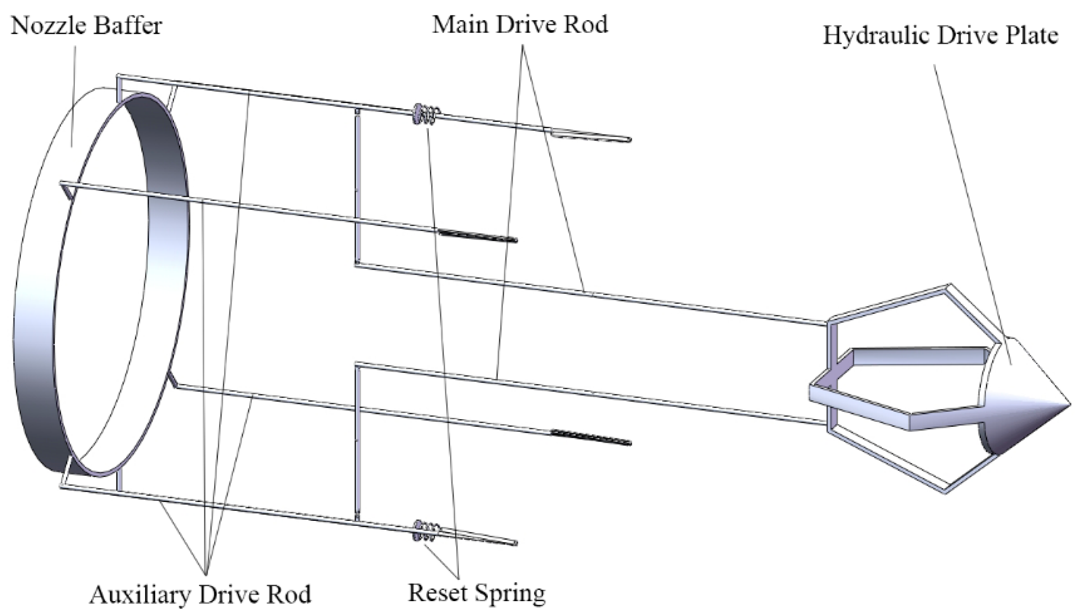
The mode-switching function is performed by changing the direction of the flushing fluid. Practically, ground facilities can usually be switched and adjusted between pumping the fluid into the flushing fluid pipe and pumping the fluid into the annulus between the pipe and the wellbore. These two modes are also known as the normal washing mode and the reverse washing mode in the field application process. Traditional mode-switching work requires a whole shutdown of the equipment not only to switch the direction of the flushing fluid but also to pull out the washing device. As shown in
Figure 5, the hydraulic drive plate is the core component of this module and is able to move forward under pressure as the flushing fluid is pumped from the inner tube and move backward as the fluid is pumped from the annulus. The auxiliary drive rod is under return spring pressure in normal washing mode, driving the nozzle baffle to block the side nozzles and jack up the filter storage module. In the reverse washing mode, the end of the hydraulic drive plate contacts with the main drive rod, pushing the main drive rod to the rear and driving the auxiliary drive rod to open the side nozzle and retract the filter storage module. The end of the hydraulic drive plate is inserted into the chute to prevent the cutting washing module from rotating in the reverse washing mode and reduce the water flow resistance caused by agitation.
3.3. Filter Storage Module
This module has the functions of filtration and storage, and its core function is to purify the returning well washing fluid and store the clogging substances in normal well washing mode. The module is mainly composed of housing, collecting plate, filter screen, and transmission pin, as shown in
Figure 6. The baffles are evenly arranged on the inner side of the housing, and a filter plate is arranged at the top of the module to filter the return liquid. Under different cleaning modes, the mode-switching module pushes and pulls the transmission pin to control the expansion and contraction states of the filter storage module.
In the normal well washing mode, the filter storage module is pushed by the drive rod of the mode-switching module and deployed into the annulus. The well washing fluid ejected from the cutting–flushing module carries mud sand to flow through the filter storage module, and pressure difference is formed at both sides of the collecting plate due to different fluid flow rates; blocking substances such as mud sand settle inside the shell under the action of pressure difference, to prevent the blocking substances from flowing back into the well. The filter plate at the rear filters the filtrate, which is initially settled, to further recover the large particle impurities in the flowback fluid. The filter storage module can effectively reduce the density of the flowback fluid and reduce the energy consumption required to recover the flowback liquid. The recovery and storage function can collect plugs inside the module, reduce the wear of cleaning equipment caused by repeated sedimentation of large particulate matter, and prolong the continuous working time of the downhole equipment.
In the reverse washing mode, the washing fluid is discharged into the wellbore from the annulus and side nozzles, and the auxiliary drive rod pulls the filter storage module back to the inner wall of the washing equipment, reducing the resistance of the module to the washing fluid and reducing the additional energy consumption that may be caused by setting the filter storage module into a fixed state.
3.4. Chain Lifting Module
The core function of the chain lifting module is to drive the winch to lock the cleaning unit through the movement of the chain and translate the cleaning device to the assembly module or the wellbore position, so as to perform the assembly and delivery of the cleaning unit. Common and specific technical standards for this module are lacking, so we suggest the following technical standards to be considered in the design process of this module: Firstly, safety standards: The components in the module should have sufficient strength to ensure the overall stability and reliability of the module during installation and operation. Secondly, performance standards: The module should have sufficient transmission capacity for the transportation and lifting of the cleaning equipment and pipe string to meet the requirements for equipment transmission capacity during lifting and lowering, and should have a certain ability to handle equipment jamming. Thirdly, material and construction standards: Equipment materials should have sufficient strength and corrosion resistance and meet transportation requirements. Equipment delivery components should use a standardized design to perform replaceable functions and meet well diameter and equipment size requirements.
The function of this module is to perform mechanical lifting and lowering. It is mainly divided into a mounting plate, chains, a winch, and connecting rods, as shown in
Figure 7. The function of the module is completely realized by mechanical force, which does not generate additional energy consumption, and is used in conjunction with the assembly module. It can reduce the manual operation required for device installation and docking and effectively improve installation and work efficiency.
As shown in
Figure 8, the chain on one side is fixed on the support frame and cannot move, while the chain on the other side is movable. The fluid pipe can be connected to the cleaning unit on the winch on the support frame. When the chain on the other side moves, it drives the gear to rotate, and the clamping piece extends out and locks the pipeline of the well flushing fluid. At the same time, the movement of the chain can drive the winch to move as a whole, and the horizontal translation of the pipeline and cleaning unit on the guide rail can be performed.
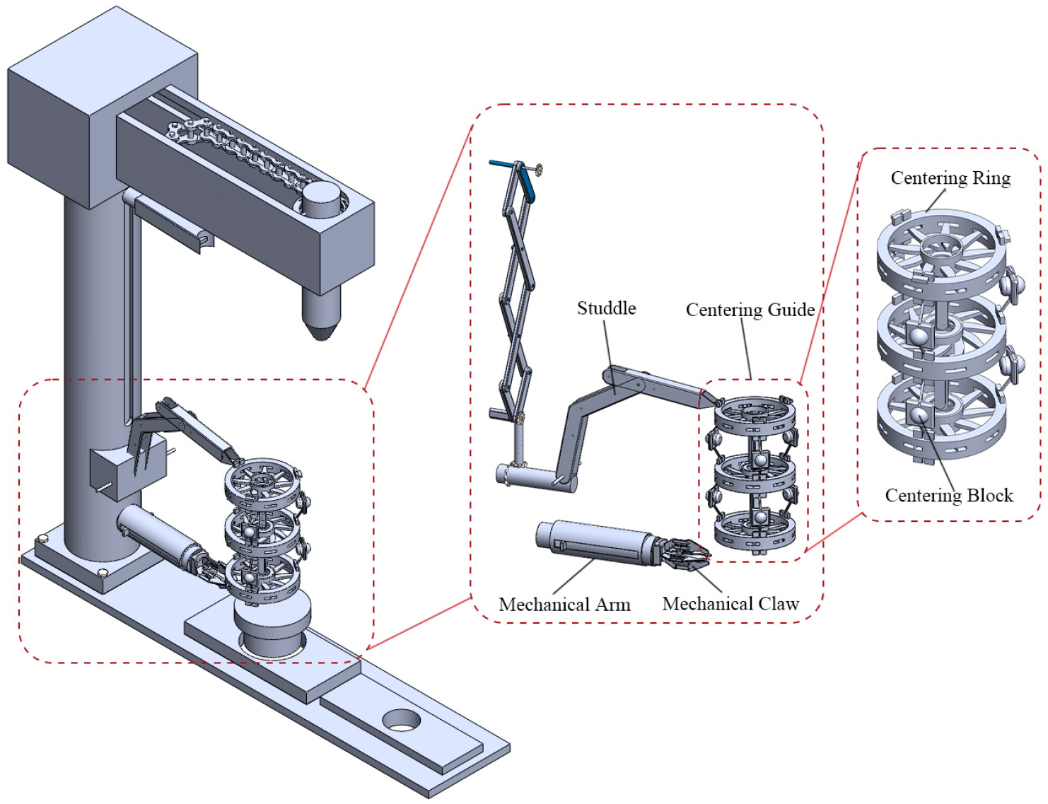
3.5. Arm Assembly Module
The module is a hydraulic arm-type operating component. As shown in
Figure 9, the module mainly includes the main support frame, a mechanical arm, a mechanical claw, a studdle, centering rings, and centering blocks. The vibration working conditions of traditional cleaning equipment mainly occur in the pulse cleaning process; even if the frequency of these vibrations is relatively low, the vibration protection performance in the structural design of traditional equipment is insufficient. The vibration working conditions at higher frequencies generated by the rotary cleaning method in this design require additional protection and equipment stability design; the vibration protection structure designed for this module can also be applied to traditional well cleaning equipment to provide it with anti-vibration capability.
The clamping claw is installed at the front end of the mechanical arm, the extension length can be adjusted through the sliding block, and the height of the supporting rod can also be adjusted through the sliding block, so as to adapt to and support the rapid replacement of well washing devices of different specifications. The mechanical arm has a multi-degree-of-freedom movement ability, which can accurately position the unit, ensure the accuracy of equipment docking, reduce the difficulty of equipment disassembly, and improve the installation efficiency. The elastic blades installed in the centering ring can reduce vibration while clamping the pipe and cleaning device. The centering rings are connected by centering blocks, which have elastic retraction capacity and cooperate with multiple centering rings to protect the stability of the device at the wellhead and prevent damage caused by accidental slippage or inclination of the device.
4. Feasibility and Prospect of Hydraulic Drive Cleaning Equipment
The hydraulic drive cleaning device is designed for well washing operations of deep wells and horizontal wells. The core principle includes hydraulic drive and mechanical assembly functions, which improve well washing maintenance efficiency for deep wells and horizontal wells and significantly improve the operation automation level. The whole device consists of two functional units: the wellbore cleaning unit and the assembly control unit. The wellbore cleaning unit comprises a hydraulic drive cutting–flushing module, a well cleaning mode-switching module, and a filter storage module, and the assembly control unit includes a chain lifting module and an arm assembly module.
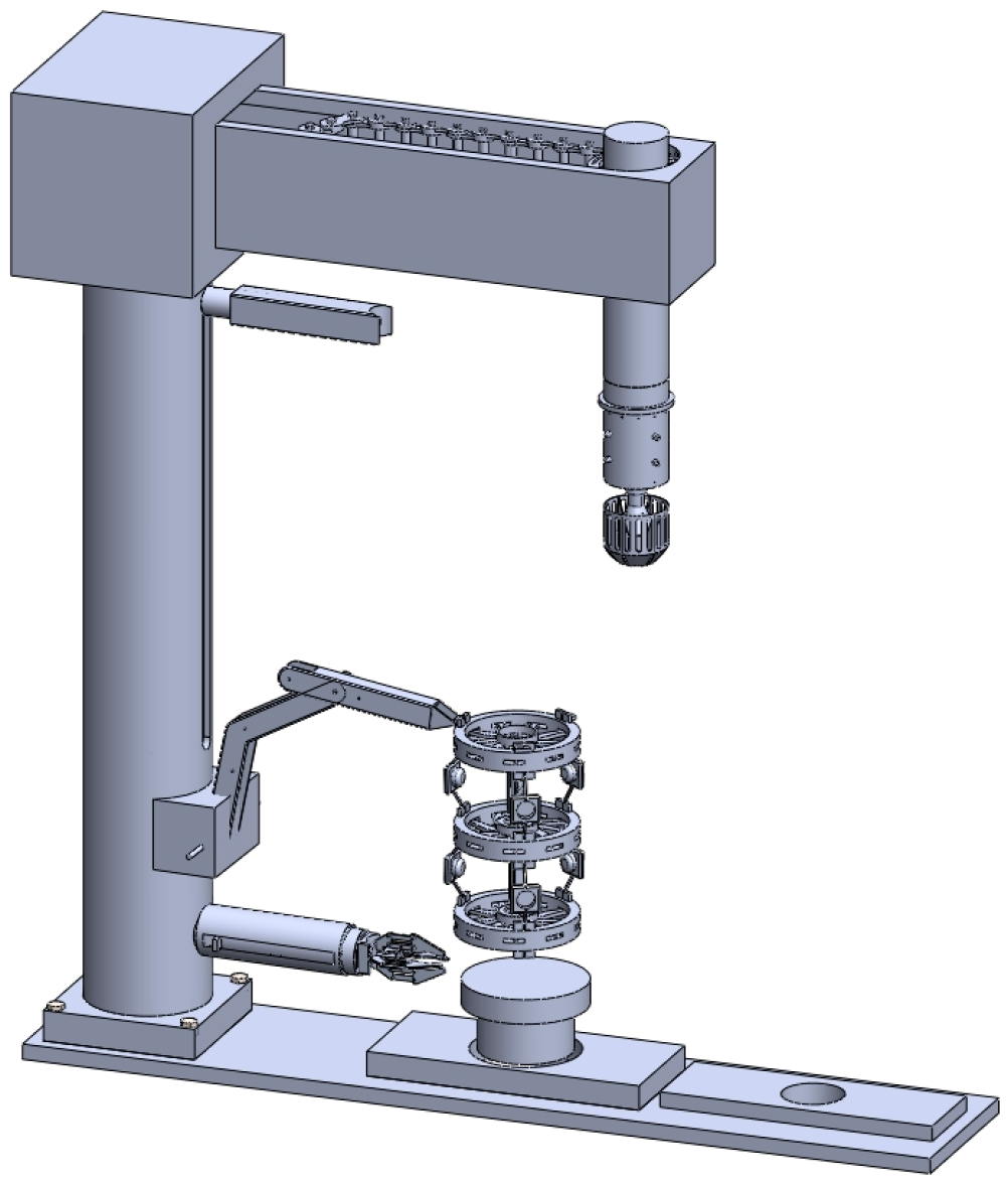
4.1. Feasibility of Hydraulic Drive Cleaning Equipment
The overall assembly design diagram of the equipment is shown in
Figure 10. Each functional module is clearly divided, which is convenient for manufacturing, maintenance, and configuration optimization under specific working conditions. Drive is obtained by utilizing the fluid energy, which reduces dependence on complex dynamical structures. It provides powerful cleaning ability through the joint action of fluid flushing and cutting-blade cutting. It performs the automatic switching of working mode by means of a well washing mode-switching module. The chain lifting module and arm assembly module significantly simplify the wellhead operation flow. The whole set of designs meets the special requirements and challenges of deep well and horizontal well interval cleaning.
Table 2 shows the risks that might occur during the process of cleaning operations. The whole equipment is designed after taking these risks into consideration. The overall structure of the cleaning equipment is mechanical without electronic components, avoiding common electromagnetic interference, unstable signal transmission, and other problems in the underground complex environment; overcoming the signal attenuation and delay problems of remote circuit control; and avoiding the failure of electronic equipment caused by extreme environments such as high temperature and high pressure. The mechanical operation mode significantly improves the stability and reliability of the equipment under harsh operating conditions. The mechanical structure responds directly with accurate action, high reliability, and strong durability, which can effectively save equipment manufacturing and maintenance costs.
Meanwhile, the mechanical driving structure can generate continuous, strong, and direction-controllable fluid flow and mechanical action, which effectively disturbs and displaces sedimentary mud and sand and inhibits the occurrence of secondary settlement. The whole structure effectively shortens the operation cycle and improves overall well cleaning efficiency. The design of the equipment can perform well in reservoir protection and wellbore permeability maintenance in deep wells and horizontal well washing.
4.2. Prospects of Hydraulic Drive Cleaning Equipment
Using a hydraulic drive cutting–flushing module to grind and clean the wellbore through the dual action of hydraulic and mechanical force can effectively remove the hard or adhesive blockage that hydraulic equipment alone cannot destroy. Fluid dynamics simulation can be used to optimize the well washing fluid channel and nozzle flow channel design to further improve the mechanical energy conversion efficiency and enhance the washing and scraping effect of the cutting washing module.
The hydraulic drive can realize the free switching of normal and reverse well washing modes during downhole work, implement sand filtering and sand collection functions on the premise of not affecting the overall strength of water flow, effectively prevent sand return caused by backflow and the settlement of sand-containing well washing fluid under horizontal conditions, and improve overall working efficiency. Further research can be conducted to optimize the design of sand collection equipment by studying the deposition law of different particle size mud and sand plugs, thus improving sand storage efficiency and enhancing anti-return effect.
The chain lifting module and arm assembly module can control the moving direction of the well washing device, reduce the working intensity of operators, and reduce the time of equipment disassembly. The application of a centering structure reduces the impact of well washer vibration on the wellbore, and the elastic structure design meets the requirements of different wellbore diameters on the centralizing structure size, which is beneficial to the stability of the cleaning device. The stress state of the whole structure can be verified through structural simulation and field continuous operation tests, and targeted strength and structure optimization can be carried out. Elastic parts can be arranged to reduce wear, enhance support, make the whole structure lightweight, and further reduce energy consumption of the device.


