Article

Simulation of Dynamic Particle Trapping and Accumulation in HGMS Based on FEM-CFD-DEM Coupling Approach

1
School of Mechanical Engineering, University of Science and Technology Beijing, Beijing 100083, China
2
Beijing Engineering Research Center on Efficient and Energy Conservation Equipment of Mineral Processing, BGRIMM Machinery and Automation Technology Co., Ltd., Beijing 100160, China
*
Author to whom correspondence should be addressed.
Processes 2025, 13(8), 2391; https://doi.org/10.3390/pr13082391
Submission received: 15 May 2025 / Revised: 4 July 2025 / Accepted: 23 July 2025 / Published: 28 July 2025
(This article belongs to the Special Issue Mineral Processing Equipments and Cross-Disciplinary Approaches)

Abstract

High-gradient magnetic separation (HGMS) is a conventional and effective method for processing weak magnetic materials. A multi-field dynamic coupling simulation method integrating the Finite Element Method (FEM), Computational Fluid Dynamics (CFD), and the Discrete Element Method (DEM) was employed to investigate the separation behavior in HGMS. The dynamic deposition process of magnetic particles under the interactions of magnetic fields, fluid flow fields, and particle–particle forces was simulated using a two-way fluid–solid coupling algorithm based on the FEM-CFD-DEM coupling approach. Experimental results demonstrated that the particle deposition profiles predicted by the double-wire medium model were in good agreement with the measured data. The research findings indicated that the separation process could be divided into three distinct stages—the adsorption stage, the closure stage, and the clogging stage—each characterized by unique dynamic behaviors and pressure-drop evolution patterns. Additionally, the effects of key parameters such as the feeding velocity and medium filling ratio on the separation process were analyzed, providing theoretical foundations and technical support for the optimization of HGMS processes and the enhancement of separation efficiency.

1. Introduction

High-gradient magnetic separation (HGMS) is a well-established and efficient technology for processing weakly magnetic materials. After nearly half a century of development, HGMS has been extensively applied in mineral processing [1,2], water treatment [3,4], and solid waste remediation [5,6,7], and more recently, its applications have expanded beyond traditional boundaries in mineral beneficiation [8]. The technology now extends to increasingly complex systems, including cell manipulation, protein purification, and other bioengineering domains [9,10,11,12,13,14,15,16,17,18,19]. Owing to its cost-effectiveness, high selectivity, and operational versatility compared to conventional separation methods, high-gradient magnetic separation has emerged as one of the most significant advanced separation techniques.
In HGMS, the wire medium model is a theoretical tool used to describe and optimize the separation behavior of magnetic particles in a high-gradient magnetic field. This model is mainly applied to analyze the sorting process of magnetic particles when they come into contact with a single wire (usually an iron wire or a metal wire) in the magnetic field. The magnetic field gradient in high-gradient magnetic separators is extremely strong, and the magnetic force acting on the particles in the gradient magnetic field is significant. The magnetic moment of magnetic particles is in the same direction as the external magnetic field, so the particles tend to move towards the strong magnetic field region, usually in the high-gradient region around the wire. The key assumption of the wire medium model is that in a strong-gradient magnetic field, magnetic particles mainly interact with these wires, and the particles are attracted by the magnetic force and adhere to the surface of the wire, eventually being separated from non-magnetic substances through fluid flow or other means. During the magnetic separation process, magnetic particles are transported through a suspension fluid. In order to study the phenomenon of high-gradient magnetic separation, the comprehensive influence of the fluid, the magnetic field, and particle diffusion on the movement of particles must be considered. Therefore, a combination of electromagnetic, fluid, and particle dynamics models is required [20].
The study of particle dynamics is an important research method in magnetic separation. Studying the force acting on particles and their behavioral characteristics is of great help in clarifying the theory of magnetic separation and the separation mechanism. The theoretical research of HGMS began with the particle trajectory model proposed by J. H. P. Watson [21] in 1973. Subsequent scholars have carried out in-depth explorations around the capture mechanism of magnetic particles: Uchiyama S et al. [22,23,24] revealed the correlation between the particle capture cross-section near the wire medium, the magnetic force, and the type of fluid and found that assumptions of potential flow and laminar flow can lead to a difference in the capture cross-section by a factor of three. William F [25] expanded the particle dynamics model of a single wire medium in the range of non-zero gravity and wide Stokes numbers and found that the inertial effect can cause trajectory oscillation. R Gerber [26] and H. Schewe [27] constructed the laminar-flow axial capture formula and the composite fluid model, respectively, with the accuracy of the laminar-flow model experimentally verified under small Reynolds numbers (0.1 < Re < 0.5). Abbasov T [28] extended the theory to non-Newtonian fluids and proposed a universal analytical expression. Koksal. M [29] established an unsteady mathematical model of magnetic filtration. Watson et al. [30,31] discovered the secondary enrichment effect of eddies on particles under high Reynolds numbers (6 < Re < 40) and proposed the theory of “eddy current magnetic separation”, but Jan Svoboda [32] questioned its applicability under low-flow-velocity conditions. These studies highlight the complexity of multi-physical field coupling in the HGMS process. In particular, the interactive influence of the flow-field conditions and particle dynamics remains the core challenge for technical optimization and industrial applications.
Research on the dynamic behavior of magnetic particles in HGMS focuses on multi-scale simulation and model optimization. Hournkumnuard K [33] used the finite difference method and parallel algorithms to numerically solve the transient concentration distribution of weakly magnetic nanoparticles, revealing the accumulation law of steady-state saturation. Mohanty et al. [34] established a three-dimensional Eulerian–Eulerian multiphase model to simulate the slurry flow between plates and combined it with the Fluent solver to predict the capture amount of magnetic particles. Khashan [35] proposed a Lagrangian–Eulerian coupling method to quantify the key parameters of magnetophoretic capture efficiency in microfluidic devices. Fei Chen [36] developed a dynamic model to study the particle accumulation process of a single-wire medium and tracked the growth front through a moving boundary but did not consider the particle detachment effect. To address this limitation, Bilgili H [37] proposed a differential dynamic equation and introduced a stochastic Fokker–Planck equation to describe the dynamic equilibrium of submicron particle capture and detachment, establishing an evolutionary model of the accumulation radius. Existing studies generally reveal that particle behavior involves the coupling of multiple physical fields, including the magnetic field, flow field, and inertia. Mesoscale magnetically induced agglomeration, collision migration, and macroscopic transport processes are intertwined, and the dynamic cycle of particle detachment (affected by system geometry, the magnetic field, and fluid parameters) has become a key constraint on model accuracy. Current models are evolving from steady-state simulations to unsteady dynamic evolution, and there is an urgent need to integrate mesoscale cluster effects and macroscopic transport mechanisms to improve prediction reliability.
In the past several years, the focus of theoretical research on high-gradient magnetic separation has shifted to using computer simulation technology to analyze the motion behavior of particles in high-gradient magnetic separation under the conditions of multiphase flow and multiple fields. Scholars Chen [36] and Lindner [38] introduced the discrete element coupling method, aiming to conduct an in-depth analysis of the shape characteristics of magnetic particle sediments on single-wire media. Specifically, Chen used the Discrete Element Method (DEM) to simulate the deposition phenomenon of magnetic particles on the wire medium at the two-dimensional level. In this process, the DEM was mainly used to accurately simulate the forces acting on the particles. Lindner simplified the simulation of the interaction forces between magnetic particles with the help of the DEM and successfully achieved the simulation of the linear agglomeration state. In addition, in order to comprehensively analyze the entire physical process, Lindner also adopted the FEM to simulate the magnetic field and used the finite volume grid to carry out CFD simulation for fluid flow. During the simulation process, the magnetic field data were read into the CFD grid to accurately determine the magnetic forces and fluid forces acting on the particles at various positions, realizing the coupling of solid and liquid phases. Compared to traditional analytical methods and single CFD approaches, this multi-method integrated simulation approach demonstrates significant advantages by accurately capturing the dynamic motion behavior of particles. The DEM-CFD coupled algorithm, combined with the dual-wire medium model, quantifies interactions between two media types while employing the discrete element method (DEM) for particle-scale tracking. This enables effective resolution of microscopic mechanisms like particle collisions and accumulation within complex heterogeneous flows, overcoming the simplified limitations of single-medium models. This multi-method synergy ensures accuracy while enabling efficient simulation of arbitrary geometric boundaries, providing a superior solution for complex multiphase flow analysis.
The traditional research object of HGMS is a single-wire medium. It studies the particle trajectory, static accumulation, dynamic accumulation, etc., of particles in the high-gradient magnetic field formed by the single-wire medium. The research model based on the adsorption process of the single-wire medium can be called the “single-wire separation model”. This model can be used for initial performance prediction and plays a certain role in understanding the adsorption and agglomeration characteristics of magnetic particles. The simplicity of its geometric rules makes the model easy to construct and implement [39,40]. In the later stage of the separation process based on the adsorption and filtration of the wire medium, the deposits between multiple wire media start to come into contact, and phenomena such as bridging and blocking occur. The assumptions of the single-wire medium model no longer hold. At this time, the analysis of the separation performance needs to be considered as a whole [41]. In order to be closer to the real separation scenario and take into account the requirements of computational efficiency, this paper adopts the “double-wire medium” as the most basic separation unit to simulate the dynamic processes such as the migration, agglomeration, and accumulation of particles in the high-gradient magnetic field formed by the double-wire medium. From the perspective of the separation pressure drop, it further explores the different stages and transformation characteristics of the separation process and systematically analyzes the specific influence of the conditional parameters on the separation effect, with the aim of obtaining a more accurate and practical understanding of the separation process. The “double-wire medium model” provides guidance for predicting the influence of different feeding rates and filling ratios on the collection efficiency in HGMS, which has significant implications for the design of separation chambers, the configuration of feeding systems, and the optimization of magnetic field orientation in HGMS applications.

2. Dynamic Coupling Model Establishment

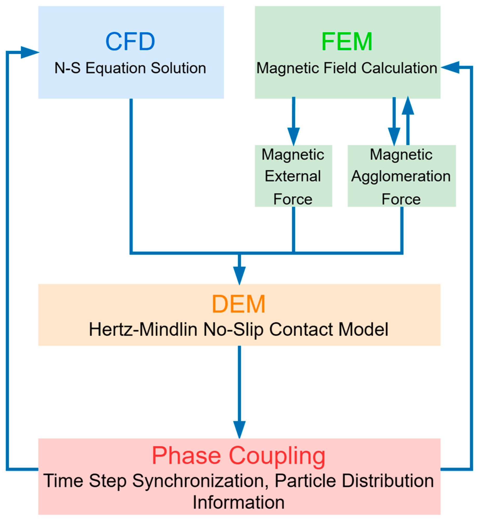
2.1. Multi-Field Coupling Calculation Model

A multi-field dynamic coupling simulation and computational platform based on FEM-CFD-DEM is established. In the literature [42], our proposed model calculates the magnetic interaction force between particles with a dynamic cyclic multi-dipole magnetic moment algorithm, revealing the relationship between particle motion characteristics and magnetic field conditions, which has laid a solid foundation for the research in this paper. Specifically, in the computational platform, within each unit time step, CFD solves and calculates the continuous flow field through the Euler equations, transmits the computational data to the DEM, and initiates the calculation. Using the DEM time step, the Newtonian equations of motion, contact force, and non-contact force equations are employed for explicit solution to update information such as particle position, energy, and velocity. This process continues until the flow time in the DEM reaches a single CFD time step. The particle information is then transmitted back to CFD for further solution and update of the flow field, followed by entering of the next time step for cyclic operations. Ultimately, dynamic coupling simulation is achieved. The framework of the multi-field dynamic coupling is shown in Figure 1.

2.1.1. Model of the Particle Phase

For the force acting on each particle, Newton’s equations are used for solution. When solid particles move in a fluid, the external force on a single particle comes from the interaction between particles and the force exerted by the fluid on the particles. This paper studies the motion state of particles in a fluid, considering only factors such as the drag force of the fluid on the particles, the gravity of the particles themselves, and collisions between particles while ignoring the influence of factors such as van der Waals forces and Brownian motion on the particles. Therefore, the motion equation of particles in the flow field is:
d d t m p v = F D + F g + F m i + F c + F e x t   ,
where m p is the mass of the particle in kg, v is the velocity of the particle in m/s, t is the time in s, F D is the fluid drag force in N, F g is the apparent gravity in N, F m i is the magnetic field force in N, F c is the collision force between particles in N, and F e x t refers to other acting forces.
The Hertz–Mindlin no-slip contact model is selected as the particle contact model. When analyzing particle collision problems using the DEM method, discrete bodies are regarded as a collection of discrete particle units with certain shapes and masses, where each particle is considered as a unit. In the DEM solution process, the adopted collision model is the soft-sphere model. Compared with the hard-sphere model, the soft-sphere model considers the collision process as time-varying and takes into account the elastic collision effect between particles. By allowing a certain amount of overlap between particles to replace the collision extrusion deformation of particles, the calculation of the contact force between particles is more in line with reality. The forces and torques between particles are expressed as follows:
I P d ω P d t = i = 1 k M i   ,
where I P is the moment of inertia of particles in kg·m2, ω P is the rotational speed of particles in rad/s, and M i is particle collision torque in N·m. For detailed calculations of forces and torques between particles, refer to ref. [9].

2.1.2. CFD Model of the Fluid

The governing equations of the fluid are solved under the assumptions that the fluid is incompressible and its dynamic viscosity and density are constant. The mass conservation equation (continuity equation) is shown as follows:
ρ t + ρ v = 0   ,
where ρ is the density of the fluid in kg/m3, v is the velocity of the flow field in m/s, t is the time in s, and refers to the vector differential operator.
The momentum conservation equation is shown as follows:
ρ v t + v v = p + μ 2 v + ρ g   ,
where p is the fluid pressure in Pa, μ is the dynamic viscosity of the fluid in Pa·s, and g is the acceleration due to gravity in m/s2. In Equation (4), the first term on the right side is the pressure gradient, the second term is the viscous force, and the third term is the gravitational force.

2.1.3. Magnetic Forces

The magnetic force ( F m ) acting on the magnetic particles can be divided into two parts: the external magnetic-field force and the magnetic agglomeration force, expressed as follows:
F m = F m e + F m i   ,
where F m e is the external magnetic-field force in N and F m i is the vector of the magnetic agglomeration force in N. The formula for F m e can be expressed as follows [10]:
F m e = 2 π r p 3 μ 0 μ r K H 2 K = μ r p μ r μ r p + 2 μ r   ,
where r p is the radius of the particle in m; μ r p and μ r are the relative magnetic permeabilities of the magnetic particle and the fluid medium, respectively (dimensionless); and H is the magnetic-field strength of the external magnetic field of the particle in A/m.
Since the magnetic agglomeration force is a non-contact force, its actual mechanical action range exceeds the physical diameter of the particles. Mutual forces arise as particles approach each other without contact, necessitating an additional action range parameter. Meanwhile, no spatial constraints are imposed on the external magnetic-field forces. In this paper, the simulation of non-contact magnetic agglomeration force is realized by setting the virtual contact radius of particles in the EDEM 2018 simulation software to be larger than the actual physical radius. To save calculation time, the calculation of magnetic force is limited to a specific distance around the particles. The calculation formula of magnetic agglomeration force between particles is expressed as follows [43]:
F m , i j = 3 μ 0 m p i m p j 4 π d 4 1 ( r i j / d ) 4 [ ( n i × n j ) + 5 ( n i n j ) ( n j n i j ) t i j ( n i t i j ) n i + ( n i t i j ) n j ] ,
where n i is the unit vector of m i ( m i = m i ) and t i j is the unit vector of r i j ( r i j = r i r j , r i j = r i j ). To reduce the error of the static magnetic dipole moment, the dynamic magnetic moment method described in ref. [42] is used to calculate the magnetic moment in this paper.

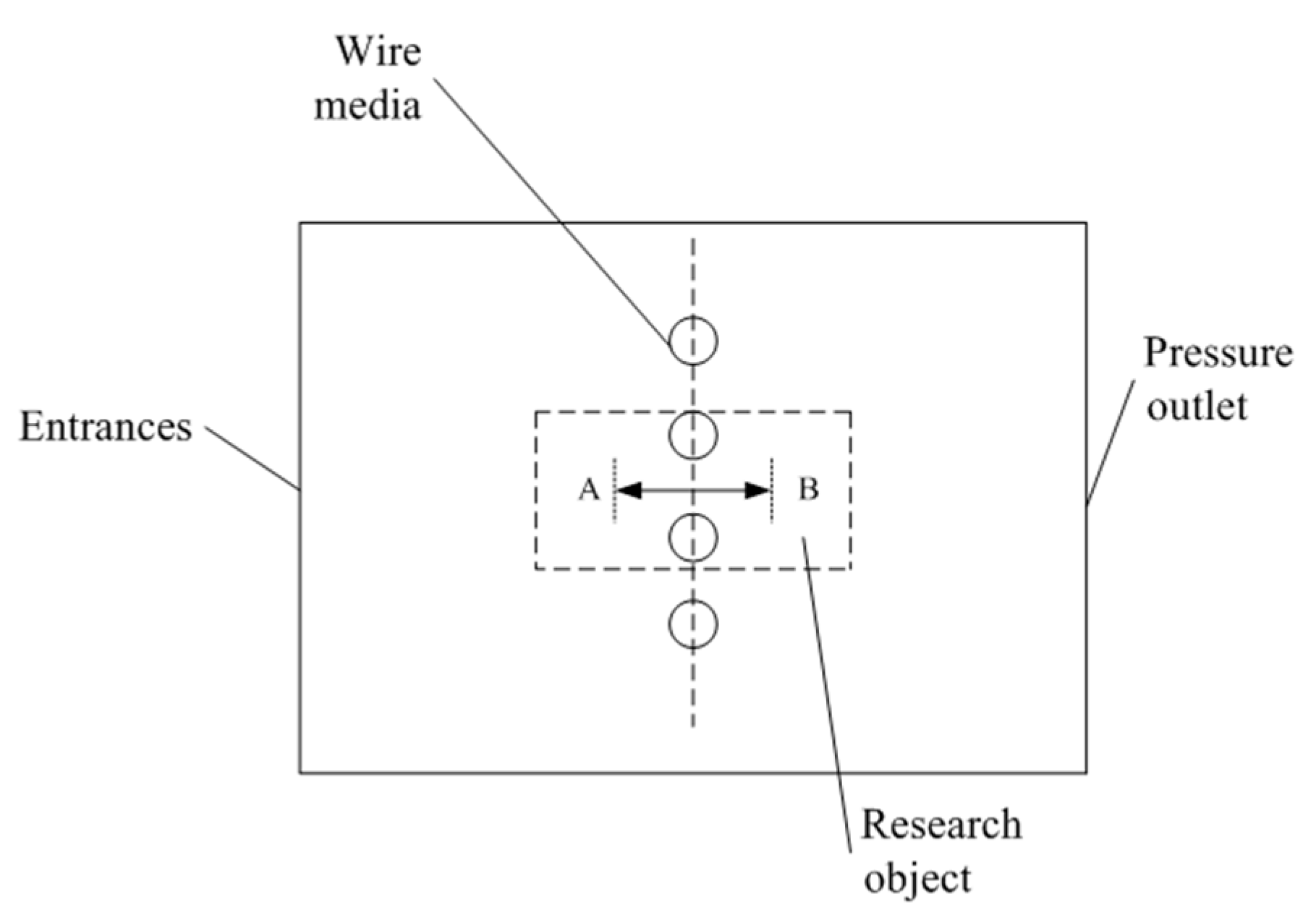
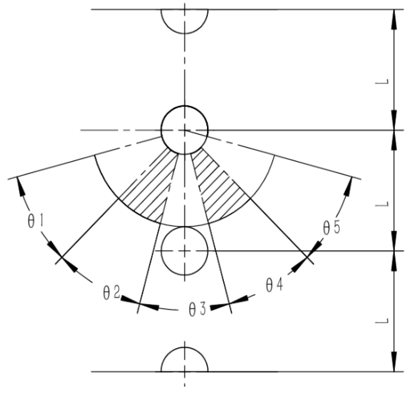
2.2. Physical Model of the Wire Medium

The geometric setup of the wire medium used in this paper is presented in Figure 2. The radius of the medium is selected as the characteristic length ( r f ) for the simulation, and the simulation area ranges are 15   mm X 15   mm , 5   mm Y 5   mm , and 5   mm Z 5   mm . Parallel cylindrical media are placed at X = 0 and Y = 0 or Y = ± L / 2 .
To simulate an infinitely large spatial domain, all four computational boundaries employ periodic boundary conditions. The boundary types are categorized as inlet, outlet, and solid wall surfaces. The inlet boundary utilizes a prescribed-velocity inlet condition, representing the uniform inflow of fluid and particles from external domains. The outlet adopts a pressure-outlet boundary condition, with particles removed from the computational domain upon crossing of the outlet boundary. Solid wall surfaces are modeled using no-slip boundary conditions. For the medium surface (wall boundary), the fluid component enforces both no-slip and no-permeation conditions, while particle interactions (including particle–particle and particle–wall collisions) are governed by an adhesive soft-sphere model.
To address the computation of high-gradient magnetic fields near wire medium in this physical model, a hybrid numerical strategy is proposed: adaptive mesh refinement is strategically deployed in regions adjacent to the wire medium to concentrate computational resources and resolve steep field gradients, while coarser grids are applied in far-field domains to optimize computational efficiency. This dual-scale approach ensures both precision in critical zones and accelerated performance in non-critical regions.
In the simulation, a two-way coupling method is employed to account for the interactions between the fluid and particles. The flow field is computed using a non-analytical CFD approach. Specifically, the flow field is recalculated every 10 fluid time steps. During each flow-field calculation, data on the particle volume fraction, drag force, and momentum from the DEM simulation are transferred to the CFD fluid grid. Through iterative solutions, a new flow field is obtained. Subsequently, field information such as fluid velocity, pressure, and viscosity is transferred to the particle positions and input into the DEM simulation to compute the drag forces acting on the particles. Table 1 lists the computational settings.
To investigate particle accumulation dynamics, we employed differential pressure monitoring as a quantitative indicator to analyze the impact of particle deposition on hydrodynamic conditions. Continuous pressure measurements were implemented at critical monitoring points (A and B) along the flow path using Fluent’s transient monitoring system, allowing for precise tracking of pressure evolution patterns throughout operational phases. This approach enabled correlation analysis between particle accumulation behavior and local fluid regime modifications.

3. Results and Discussion

3.1. Experimental Set-Up

Figure 3 is a diagram of the experimental wire medium particle capture system established in this study. The basic process of the experimental system is to release the magnetic particles first, then conduct experimental observations on the growth of magnetic agglomerates. The fine particles used in the particle capture experiment of the wire medium (made of SUS430 material with a saturation magnetization of 1.53 T) are required to be monodisperse and have uniform particle sizes, which is convenient for observing the accumulation and stacking growth of the particles. In this experiment, a micro-stirring syringe pump is used as the particle generator. During the experiment, a ball screw is controlled by a servo motor to inject the particle suspension into the flow cell at a constant flow rate.
The experimental observation part consists of an experimental flow cell, a wire medium support, and a high-speed camera. Experiments on the adsorption and accumulation of particles on the wire medium are mainly carried out, and the experimental process and results are observed. Two permanent magnets with dimensions of 50 × 10 × 10 mm (length × width × height) and an inherent magnetization of 1.3 T are placed in the flow cell. The magnetization direction is perpendicular to the flow direction of the flow cell, constructing a vertical configuration of the single-wire HGMS system. The experimental results are recorded through real-time observation by a high-speed camera. The high-speed camera used is a Fastcam Mini UX high-speed camera, along with a light source and a computer. The light source is an LED side-emitting flat-panel light produced by Xinmengtai Company, with dimensions of 30 × 60 cm, a rated power of 55 W, and a color temperature of 4000 K. A Fastcam Mini UX high-speed camera serves as the core component of this system. This type of camera is developed by PHOTRON Company; its maximum shooting speed (full frame) can reach 4000 fps, the maximum resolution is 1280 × 1024, the shortest exposure time is 1 μs, the pixel size can reach 10 μm, and its external dimensions are 120 × 100 × 90 mm. Its AC power supply is applicable within the ranges of 100~240 V, 50~60 HZ, and 40 VA.
To validate the effectiveness of the established model, a double-wire medium HGMS experiment was conducted in an experimental particle capture system to verify the simulation results. The particles used in the experiment were polystyrene magnetic fluorescent microspheres (ZKKY-PSCY-1-70). These particles had a diameter of 70 μm with a standard deviation of 0.01 μm, indicating good uniformity. The reagent was a liquid suspension with particles dispersed in water. The particle density was 1050 kg/m3—close to that of water, ensuring favorable sphericity and dispersibility.

3.2. Experimental Results

The left panel of Figure 4 presents a cumulative-state image obtained from the experiment, from which the stacking profile (yellow solid line) can be extracted. Simulations were conducted under identical conditions, and the stacking profile (black solid line) of the simulation results was similarly extracted, as shown in the right panel of Figure 4. A comparison of the stacking profiles between the experiment and the simulation is shown in Figure 5. In Figure 5, B represents the background magnetic field strength, and the pink frame indicates the region between two double wires. It can be observed that the experimental and simulated profiles exhibit good coincidence within the inter-wire region, with the simulation predictions more closely approximating the experimental outcomes.

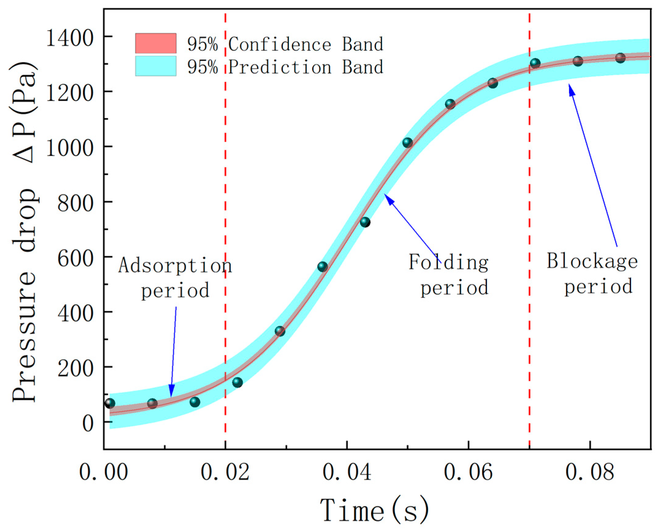
3.2.1. Division and Characteristics of the Separation Stage

Figure 6 shows the relationship between the pressure drop during the deposition process and the separation time under this working condition. The pressure drop during the separation process is obtained by comparing the pressures at the detection points in the simulation area. According to the relationship between the separation pressure drop and time (the amount of particle deposition), the high-gradient magnetic separation process can be divided into three distinct stages: the adsorption stage, the closure stage, and the clogging stage.
During the adsorption stage, the pressure-drop growth rate is the slowest throughout the entire cycle, and the specific evolution characteristics are as shown in the figure. During this stage, particles preferentially deposit in the high-magnetic-field gradient area near the wire medium. Its kinetic mechanism is manifested as follows:
(1)
Characteristics of the dominant force field: The external magnetic force serves as the core driving force, significantly suppressing the scouring effect of the fluid drag force on the deposited particles under low-flow-rate conditions;
(2)
Stability of the spatial structure: The initially deposited body has not yet formed a continuous structure, and the magnetic field distribution between the wire media and the flow channel remains in the original state, without a significant flow-channel contraction effect;
(3)
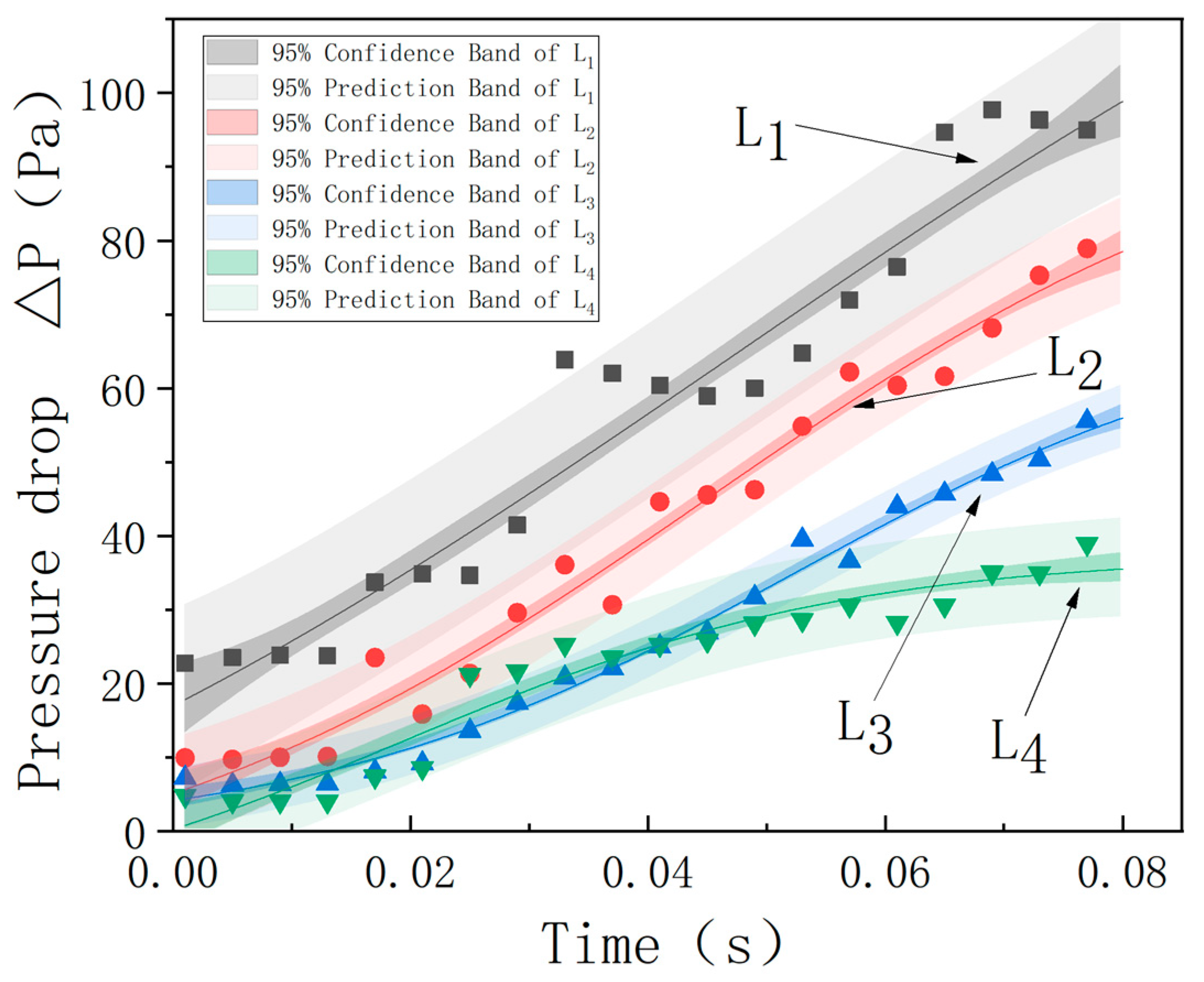
Characteristics of energy dissipation: The particle accumulation process is mainly in the form of discrete point contacts, without triggering large-scale eddy currents or turbulent kinetic energy loss. Due to the coupling effect of the multiple factors mentioned above, the resistance of the flow field in the deposition layer only increases linearly with the deposition mass, resulting in a gentle increase in the pressure drop between the monitoring points. In essence, this stage is the initial construction process of the directional arrangement of particles in a single layer driven by the magnetic field, laying a structural foundation for the agglomeration and aggregation in the subsequent stages.
The “closure stage” marks the key stage of particle bridging and closing in the adsorption process. Compared with the slow, linear increase in the initial stage, the pressure-drop growth rate in this stage significantly increases, and it has an approximately linear relationship with the adsorption time. As shown in Figure 7, in the vertical configuration, the particle chains preferentially extend along the direction of the magnetic field gradient, forming a nearly fan-shaped structure.
From the microscopic evolution shown in Figure 8, it can be seen that the particles are mainly deposited directionally in the magnetic field attraction area between the wire media. As the cumulative structure expands, the distance between the wires is gradually compressed. This geometric constraint leads to the contraction of the flow channel. The closed particles reduce the flow cross-section, and the local increase in flow velocity directly causes a sharp increase in the pressure drop, driving the pressure drop in the “closure stage” into a rapid upward channel, laying a kinetic foundation for the complete blocking in the subsequent stage.
The adsorption, deposition, and clogging stage is characterized by the intersection and closing of the particle chains in the flow channel to form a continuous closed structure. During this stage, the magnetic deposited bodies between the wire media present a loose and porous morphology. As shown in Figure 9, there is a void network inside, still allowing fluid and some non-magnetic particles to pass through.
As the particles continuously fall, squeeze, and fill the gaps between the wire media, the porosity of the deposited body decreases: the large pores in the loose structure in the initial stage are first filled with magnetic particles, resulting in a sharp reduction in the cross-sectional area of the main fluid channel. The slope of the pressure-drop curve in this stage is the largest, indicating that the system resistance reaches the peak growth rate in the early stage of a full load. After the gaps between the wires are basically filled, the surface of the deposited body tends to be dense and flat. The subsequent compaction process mainly relies on the rearrangement of particles to increase the packing density until the flow channel is completely closed to achieve full load. The essence of the evolution during the entire clogging stage is the dynamic transformation process of the pore structure from an open and connected state to a closed and dense state.

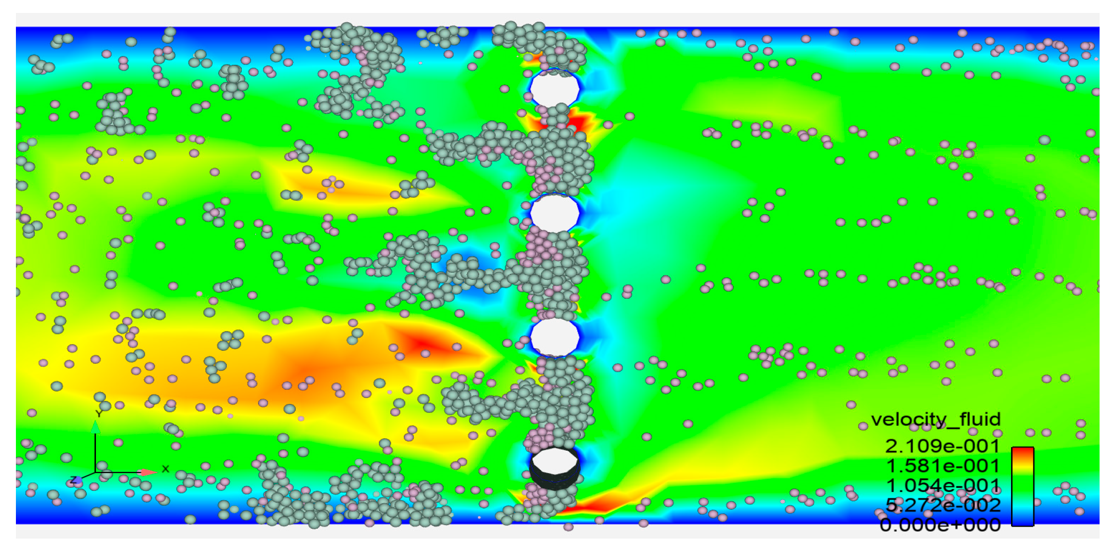
3.2.2. Changes in the Number of Magnetic Particles in Different Regions

The agglomeration separation process includes particle deposition; intersection and closing; and, finally, blocking. In order to further understand the agglomeration mechanism of magnetic particles, the structure of the particle layer is analyzed to clarify the agglomeration mechanism of the particle layer. In order to quantitatively reflect the structural characteristics of the deposited agglomerates, the pressure drop and the number of particles within the local sector are used for characterization. According to the previous description, particle attraction and agglomeration go through three accumulation periods. We further focus on the changes in the particle deposition structure to reveal the influence of the magnetic force on the particle accumulation state in the particle structure layer.
First, the adsorption regions of the double-wire medium with different configurations are divided; then, the number of particles in different adsorption regions is counted, as shown in Figure 10. A sector angle within a range of 150° is selected and divided into five small sector regions ( θ 1 θ 5 ) for statistical calculation.
The local volume fraction of the adsorbent structure was calculated at different times under the parallel configuration. Figure 11 shows the dynamic particle distribution in different fan-shaped regions under the vertical configuration. From the results, it can be found that with an increase in the collection time, the cumulative number of particles in different fan-shaped regions gradually increases. Among them, the growth trends of the number of particles in different regions are different. The number of particles in region θ 3 grows the fastest, and the growth of the number of particles in region θ 1 and region θ 5 is relatively slow. The increase in the number of particles ( Δ N p ) between region θ 2 and region θ 4 is close. Since the particles are uniformly released, it can be seen that the adsorption capacity of region θ 3 is the strongest, and the volume fractions of the regions on both sides also conform to the characteristics of dynamic adsorption and are the same as the distribution region of the additional magnetic field after the wire medium is magnetized.

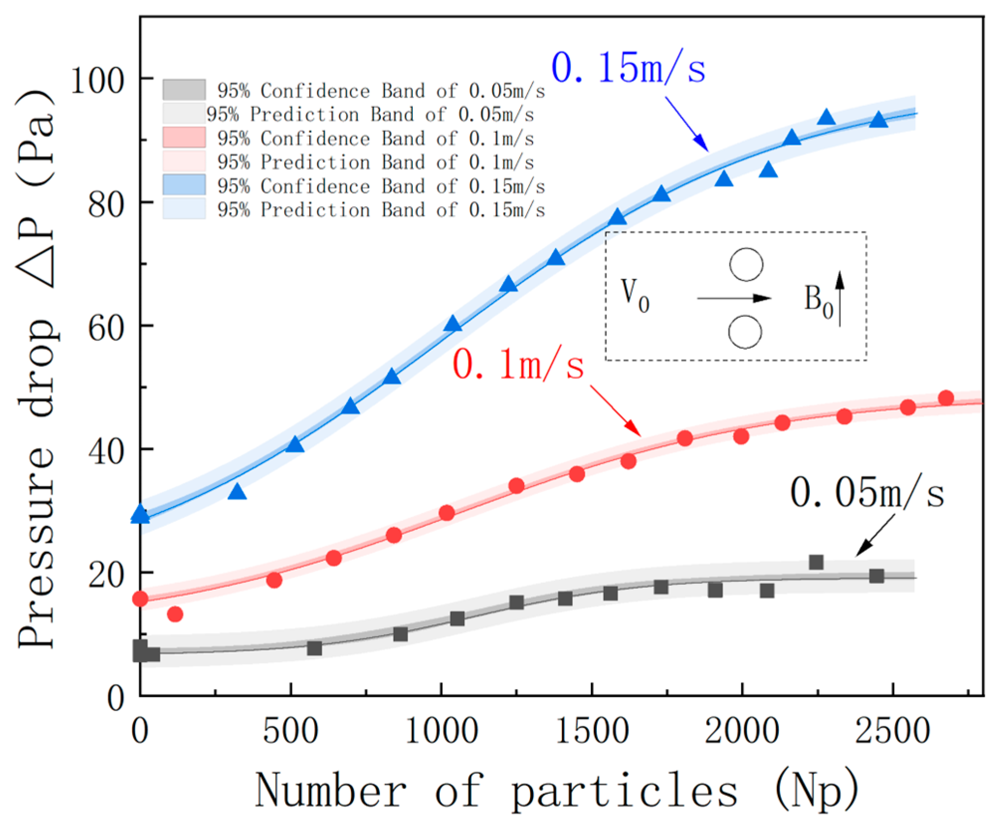
3.2.3. Influences of Separation Parameters on the Separation Process

(1)
Feeding Velocity
The feeding velocity is a critical parameter in HGMS. During the HGMS process, the feed is pumped into the system. Altering the feeding velocity changes the fluid dynamics within the medium, which, in turn, affects the structural morphology and strength of the particle deposits. Based on the reference operating conditions, we varied the feeding velocity to analyze its impact on the particle deposition process and separation pressure drop. The feeding velocities were set at 0.05 m/s, 0.1 m/s, and 0.15 m/s according to industrial practices. The relationship between the pressure drop and the cumulative number of particles is shown in Figure 12. Notably, the inset in Figure 12 depicts the feeding direction and magnetic field orientation.
As can be seen from Figure 12, with an increase in the ore feeding speed, the separation pressure drop shows an obvious upward trend. Specifically, when the ore feeding speed is low (such as 0.05 m/s and 0.1 m/s), the fluid flows slowly in the medium, and the particles are subject to relatively low resistance during the deposition process, so the pressure drop (<40 Pa) is also small. At this time, the particle deposition is mainly concentrated on the surface of the medium, forming a relatively loose deposition layer, which helps to maintain a low pressure-drop level.
However, as the ore feeding speed increases (0.15 m/s), the fluid flow speed in the medium accelerates, and the impact force on the particles during the deposition process increases, resulting in a more compact particle deposition and an increase in the thickness of the deposition layer, significantly increasing the pressure drop. When the ore feeding speed is 0.15 m/s, due to the large fluid impact force, the particle deposition layer becomes denser, resulting in a higher pressure drop. Nevertheless, the cumulative deposition amounts under different ore feeding speeds show similar trends, that is, when entering the particle layer stage, the cumulative deposition amounts are basically the same. This phenomenon indicates that although the ore feeding speed affects the speed and mode of particle deposition, the final total deposition amount is stable to a certain extent. In addition, the pressure-drop curve shows stage characteristics. In the initial stage, due to the presence of less particle deposition, the pressure drop increases slowly; as the deposition amount increases, the pressure drop gradually rises, and until entering the particle layer stage, the pressure drop increases rapidly. This stage change reflects the dynamic behavior of magnetic particles during the adsorption and separation process, revealing the internal law of the particle deposition process.
(2)
Filling Ratio
The spacing of the wire medium is an important parameter in HGMS, which represents the change of the filling ratio. A lower filling ratio means that the volume proportion of the wire medium in the separation cavity is smaller, and there is less superposed magnetic field between the wire media, making it more difficult for bridging to occur between the particle deposits. A higher filling ratio indicates that the volume proportion of the wire medium in the separation cavity is larger, making it easier for bridging to happen between the particle deposits and more likely to cause blockage. In this section, based on the reference working conditions, the spacing of the wire medium is changed to regulate the filling density; then, the influences on the dynamic accumulation process of particles and the pressure drop are analyzed. When choosing the spacing of the wire medium, the collection radius is taken into account first, and at the same time, the influences of the superposed magnetic field and the filling ratio in practical industrial applications are considered. The working conditions set for this time are listed in Table 2.
Figure 13 shows the relationship between the separation pressure drop and time under different wire medium spacings in the vertical configuration. As can be seen from the figure, after the particles are adsorbed by the wire media with different spacings, the pressure drop of the wire media is significantly affected. For a single fixed spacing, as time increases, the pressure drop ( P ) between the media shows an obvious staged pattern; for different wire medium spacings, the variation ranges of the pressure drop are different. As the spacing increases, the increasing amplitude of the pressure drop decreases.
To further analyze the influence of different spacings on the agglomeration and accumulation of particles, as can be seen from Figure 14, for a single fixed spacing, as time increases, the particle concentration between the media also shows an obvious staged pattern; for different wire medium spacings, the variation ranges of the number of particles are different, and as the spacing increases, the increasing amplitude of the number of particles in a fixed area also decreases.
The spacing of the wire medium, a critical control parameter in HGMS systems, directly determines the packing density distribution within separation chambers. When wire medium spacing increases, the sparse arrangement weakens magnetic field superposition effects. Simultaneously, particle deposits must traverse longer distances to achieve bridging, thereby reducing bridging probability. Conversely, reducing the wire medium spacing enhances magnetic-field superposition through localized magnetic gradient intensification, promoting inter-particle attraction and accelerating bridging initiation. However, this geometric configuration introduces higher hydrodynamic resistance due to reduced flow-channel dimensions.
These opposing effects underscore the necessity of geometric optimization in HGMS design. Our analysis reveals that achieving optimal system performance requires the balancing of magnetic capture efficiency with fluid permeability through strategic parameter adjustment. The interplay between wire medium spacing, magnetic field distribution, and fluid flow patterns fundamentally governs the system’s transition from stable particle accumulation to critical blockage conditions. This insight provides a theoretical foundation for advancing industrial-scale HGMS matrix design, particularly in maintaining operational stability under high-solid-flux scenarios.

4. Conclusions

This paper takes the high-gradient magnetic separation process as the research object and adopts the DEM-CFD fluid–solid two-way coupling algorithm to study the particle separation process. Under the combined influence of the external magnetic force and the magnetic interaction force, through statistical analysis of the separation pressure drop, the number of deposited particles, etc., this paper studies the influence of the agglomeration of magnetic particles on the fluid flow and the magnetic field around the double-wire medium. At the same time, it also analyzes the influence of the fluid on the position of the particles agglomerated around the wire medium.
Experimental verification shows that the particle-stacking profile simulated by the double-wire model has a high degree of agreement with the measured data. Therefore, the double-wire region can be used as the research object to study the separation process. The separation process includes three stages: adsorption, closure, and clogging. During the adsorption stage, particles preferentially deposit in the high-magnetic-field gradient region near the double wires, and the pressure drop increases slowly; during the closure stage, particles extend along the magnetic field direction to form a nearly fan-shaped structure; during the clogging stage, particles close to form a closed structure, and the pressure-drop growth rate reaches its peak.
The feeding velocity, background magnetic field, and filling ratio are the core influencing factors. An increase in the feeding velocity will enhance the fluid impact force, leading to the densification of the deposition layer and an increase in pressure. It is necessary to balance the filtration efficiency and the risk of blockage. The intensity of the background magnetic field determines the driving force for particle adsorption and affects the stability of the agglomeration structure; an increase in the filling ratio can enhance the magnetic field superposition effect and improve the collection efficiency, but it may accelerate the blockage of the flow channel.

Author Contributions

Methodology, X.W. and Y.H. (Yonghui Hu); software, X.W. and Y.H. (Yefei Hao); validation, G.L. and M.Z.; formal analysis, X.W.; investigation, Y.H. (Yonghui Hu); data curation, G.L.; writing—original draft preparation, X.W. and Y.H. (Yefei Hao); writing—review and editing, Y.H. (Yonghui Hu); visualization, X.W.; supervision, Y.H. (Yonghui Hu); project administration, X.W. and Z.S.; funding acquisition, Z.S. and M.Z. All authors have read and agreed to the published version of the manuscript.

Funding

This work was supported by grants from the National Key Research and Development Program of China (No. 2021YFC2902400).

Data Availability Statement

Data are contained within the article.

Acknowledgments

This work was carried out at the National Supercomputer Center in Tianjin, and the calculations were performed on TianHe-1 (A).

Conflicts of Interest

Authors Xiaoming Wang, Yonghui Hu, Yefei Hao, Zhengchang Shen, Guodong Liang, and Ming Zhang were employed by the BGRIMM Machinery and Automation Technology Co., Ltd. The authors declare that the research was conducted in the absence of any commercial or financial relationships that could be construed as a potential conflict of interest.

References

  1. Singh, S.; Sahoo, H.; Rath, S.S.; Sahu, A.K.; Das, B. Recovery of iron minerals from Indian iron ore slimes using colloidal magnetic coating. Powder Technol. 2015, 269, 38–45. [Google Scholar] [CrossRef]
  2. Peng, N.; Pan, Q.; Liu, H.; Yang, Z.; Wang, G. Recovery of iron and manganese from iron-bearing manganese residues by multi-step roasting and magnetic separation. Miner. Eng. 2018, 126, 177–183. [Google Scholar] [CrossRef]
  3. Miura, O.; Tachibana, S. Mercury Removal from Solution by High Gradient Magnetic Separation with Functional Group Modified Magnetic Activated Carbon. IEEE Trans. Appl. Supercond. 2014, 24, 3700904. [Google Scholar] [CrossRef]
  4. Oka, T.; Takayanagi, Y.; Machida, S.; Ichiju, K.; Fukui, S.; Ogawa, J.; Sato, T.; Ooizumi, M.; Tsujimura, M.; Yokoyama, K. Magnetic Separation for Recovering Ni Compounds from Plating Waste with Use of HTS Bulk Magnets. IEEE Trans. Appl. Supercond. 2016, 26, 3700204. [Google Scholar] [CrossRef]
  5. Kim, J.E.; Ha, D.W.; Kim, Y.H. Separation of Steel Slag from Landfill Waste for the Purpose of Decontamination Using a Superconducting Magnetic Separation System. IEEE Trans. Appl. Supercond. 2015, 25, 3700404. [Google Scholar] [CrossRef]
  6. Yamashita, M.; Akai, T.; Murakami, M.; Oki, T. Recovery of LaPO4:Ce,Tb from waste phosphors using high-gradient magnetic separation. Waste Manag. 2018, 79, 164–168. [Google Scholar] [CrossRef]
  7. Yang, C.; Li, S.; Yang, R.; Bai, J.; Guo, Z. Recovery of silicon powder from kerf loss slurry waste using superconducting high gradient magnetic separation technology. J. Mater. Cycles Waste Manag. 2018, 20, 937–945. [Google Scholar] [CrossRef]
  8. Ahmed, N.; Li, X.; Xue, Z.; Ren, X.; Huang, H.; Chen, L. Enhancing PHGMS performance for recovery of ultra-fine ilmenite from tailings. Physicochem. Probl. Miner. Process. 2024, 60, 189617. [Google Scholar] [CrossRef]
  9. Chen, H.; Ebner, A.D.; Kaminski, M.D.; Rosengart, A.J.; Ritter, J.A. Analysis of magnetic drug carrier particle capture by a magnetizable intravascular stent—2: Parametric study with multi-wire two-dimensional model. J. Magn. Magn. Mater. 2005, 293, 616–632. [Google Scholar] [CrossRef]
  10. Marshall, J.S. Discrete-element modeling of particulate aerosol flows. J. Comput. Phys. 2009, 228, 1541–1561. [Google Scholar] [CrossRef]
  11. Avilés, M.O.; Ebner, A.D.; Chen, H.; Rosengart, A.J.; Kaminski, M.D.; Ritter, J.A. Theoretical analysis of a transdermal ferromagnetic implant for retention of magnetic drug carrier particles. J. Magn. Magn. Mater. 2005, 293, 605–615. [Google Scholar] [CrossRef]
  12. Misael OAvilés Ebner, A.D.; Ritter, J.A. Ferromagnetic seeding for the magnetic targeting of drugs and radiation in capillary beds. J. Magn. Magn. Mater. 2007, 310, 131–144. [Google Scholar] [CrossRef]
  13. Larimi, M.M.; Ramiar, A.; Ranjbar, A.A. Numerical simulation of magnetic nanoparticles targeting in a bifurcation vessel. J. Magn. Magn. Mater. 2014, 362, 58–71. [Google Scholar] [CrossRef]
  14. Haverkort, J.W.; Kenjereš, S.; Kleijn, C.R. Computational Simulations of Magnetic Particle Capture in Arterial Flows. Ann. Biomed. Eng. 2009, 37, 2436–2448. [Google Scholar] [CrossRef] [PubMed]
  15. Wang, S.; Zhou, Y.; Tan, J.; Xu, J.; Yang, J.; Liu, Y. Computational modeling of magnetic nanoparticle targeting to stent surface under high gradient field. Comput. Mech. 2014, 53, 403–412. [Google Scholar] [CrossRef]
  16. Cregg, P.J.; Murphy, K.; Mardinoglu, A. Inclusion of interactions in mathematical modelling of implant assisted magnetic drug targeting. Appl. Math. Model. 2012, 36, 1–34. [Google Scholar] [CrossRef]
  17. Hournkumnuard, K.; Natenapit, M. Magnetic drug targeting by ferromagnetic microwires implanted within blood vessels. Med. Phys. 2013, 40, 062302. [Google Scholar] [CrossRef]
  18. Sharma, S.; Singh, U.; Katiyar, V.K. Modeling and in vitro study on capture efficiency of magnetic nanoparticles transported in an implant-assisted cylindrical tube under magnetic field. Microfluid. Nanofluidics 2015, 19, 1061–1070. [Google Scholar] [CrossRef]
  19. McFarlane, J.; Weber, C.; Wiechert, A.; Yiacoumi, S.; Tsouris, C. High-gradient magnetic separation of colloidal uranium oxide particles from soil components in aqueous suspensions. Colloids Surf. C Environ. Asp. 2024, 2, 100023. [Google Scholar] [CrossRef]
  20. Okada, H.; Mitsuhashi, K.; Ohara, T.; Whitby, E.R.; Wada, H. Computational Fluid Dynamics Simulation of High Gradient Magnetic Separation. Sep. Sci. Technol. 2005, 40, 1567–1584. [Google Scholar] [CrossRef]
  21. Watson, J.H.P. Magnetic filtration. J. Appl. Phys. 1973, 44, 4209–4213. [Google Scholar] [CrossRef]
  22. Uchiyama, S.; Takayasu, M.; Kurinobu, S. Performance of parallel-stream-type magnetic filter for high gradient magnetic separation. Trans. Inst. Electr. Eng. Jpn. 1977, 97, 75–82. [Google Scholar] [CrossRef]
  23. Uchiyama, S.; Kondo, S.; Takayasu, M.; Eguchi, I. Performance of parallel stream type magnetic filter for HGMS. IEEE Trans. Magn. 1976, 12, 895–897. [Google Scholar] [CrossRef]
  24. Uchiyama, S.; Kurinobu, S.; Kumazawa, M.; Takayasu, M. Magnetic particle buildup processes in parallel stream type HGMS filter. IEEE Trans. Magn. 1977, 13, 1490–1492. [Google Scholar] [CrossRef]
  25. Lawson, W.F.; Simons, W.H.; Treat, R.P. The dynamics of a particle attracted by a magnetized wire. J. Appl. Phy. 1977, 48, 3213–3224. [Google Scholar] [CrossRef]
  26. Gerber, R. Theory of particle capture in axial filters for high gradient magnetic separation. J. Phys. D Appl. Phys. 2001, 11, 2119. [Google Scholar] [CrossRef]
  27. Schewe, H.; Takayasu, M.; Friedlaender, F. Observation of particle trajectories in an HGMS single-wire system. IEEE Trans. Magn. 1980, 16, 149–154. [Google Scholar] [CrossRef]
  28. Abbasov, T.; Gebakan, V.; Karada, T. Particle capture modeling for an axial magnetic filter with a bounded non-Newtonian flow field. Powder Technol. 2015, 291, 223–228. [Google Scholar] [CrossRef]
  29. Kksal, M.; Abbasov, T.; Herdem, S. Mathematical Modeling of the Magnetic Filtration Processes. Int. J. Appl. Electromagn. Mech. 2003, 18, 227–234. [Google Scholar] [CrossRef]
  30. Li, Z.; Watson, J.H.P. A study of vortex magnetic separation (VMS) with a high-speed video system. Miner. Eng. 1994, 7, 759–768. [Google Scholar] [CrossRef]
  31. Zn, L.I.; Watson, J.H.P. Vortex magnetic separation (VMS). IEEE Trans. Magn. 1994, 30, 4662–4664. [Google Scholar] [CrossRef]
  32. Svoboda, J. Vortex magnetic separation: An illusion or reality. Miner. Eng. 1995, 8, 571–573. [Google Scholar] [CrossRef]
  33. Hournkumnuard, K.; Chantrapornchai, C. Parallel simulation of concentration dynamics of nano-particles in High Gradient Magnetic Separation. Simul. Model. Pract. Theory 2011, 19, 847–871. [Google Scholar] [CrossRef]
  34. Mishra, S.M.D.K. A preliminary investigation into magnetic separation process using CFD. Miner. Eng. 2011, 24, 1651–1657. [Google Scholar] [CrossRef]
  35. Khashan, S.A.; Furlani, E. CFD-based, Lagrangian-Eulerian coupling approach for magnetophoretic particle capture. In Proceedings of the Micro & Nano Flows Conference, Thessaloniki, Greece, 22–24 August 2011. [Google Scholar]
  36. Chen, F.; Smith, K.A.; Hatton, T.A. Alan Hatton.A dynamic buildup growth model for magnetic particle accumulation on single wires in high-gradient magnetic separation. Aiche J. 2012, 58, 2865–2874. [Google Scholar] [CrossRef]
  37. Bilgili, H.; Kele, C.; Abbasov, T. Modeling of the Particle Build-Up Evolution on a Single-Wire Magnetic Capture from Axial Stream Flow. Magnetochemistry 2022, 8, 15. [Google Scholar] [CrossRef]
  38. Lindner, J.; Menzel, K.; Nirschl, H. Simulation of magnetic suspensions for HGMS using CFD, FEM and DEM modeling. Comput. Chem. Eng. 2013, 54, 111–121. [Google Scholar] [CrossRef]
  39. Cowen, C.; Friedlaender, F. Single wire model of high gradient magnetic separation processes III. IEEE Trans. Magn. 1977, 12, 466–470. [Google Scholar] [CrossRef]
  40. Bai, H.; Qian, X.; Fan, J.; Shi, Y.; Duo, Y.; Guo, C.; Wang, X. Theoretical Model of Single Fiber Efficiency and the Effect of Microstructure on Fibrous Filtration Performance: A Review. Ind. Eng. Chem. Res. 2020, 60, 3–36. [Google Scholar] [CrossRef]
  41. Tao, R.; Yang, M.; Li, S. Effect of adhesion on clogging of microparticles in fiber filtration by DEM-CFD simulation. Powder Technol. 2020, 360, 289–300. [Google Scholar] [CrossRef]
  42. Wang, X.; Shen, Z.; Hu, Y.; Liang, G. Dynamic Coupling Model of the Magnetic Separation Process Based on FEM, CFD, and DEM. Processes 2025, 13, 1303. [Google Scholar] [CrossRef]
  43. Satoh, A.; Coverdale, G.N.; Chantrell, R.W. Stokesian Dynamics Simulations of Ferromagnetic Colloidal Dispersions Subjected to a Sinusoidal Shear Flow. J. Colloid Interface 2000, 231, 238–246. [Google Scholar] [CrossRef]
Figure 1. Framework of the multi-field dynamic coupling model based on FEM-CFD-DEM.
Processes 13 02391 g001
Figure 2. The calculation area and boundary conditions of the double-wire model.
Processes 13 02391 g002
Figure 3. Schematic diagram of the experimental HGMS particle capture system. Different colors represent different experimental devices.
Processes 13 02391 g003
Figure 4. Experimental (left) and simulation (right) results and the extraction of their particle accumulation profiles.
Processes 13 02391 g004
Figure 5. Comparison of the results of the particle accumulation profiles between the experiment and the simulation.
Processes 13 02391 g005
Figure 6. Pressure drop in the vertically configured double-wire medium.
Processes 13 02391 g006
Figure 7. Adsorption-stage dynamics of vertically configured double-wire medium.
Processes 13 02391 g007
Figure 8. Closure-stage dynamics of vertically configured double-wire medium.
Processes 13 02391 g008
Figure 9. Clogging-stage dynamics of vertically configured double-wire medium.
Processes 13 02391 g009
Figure 10. Double-wire medium vertical configuration with fan-shaped analysis regions.
Processes 13 02391 g010
Figure 11. Particle change curves in different fan-shaped regions in the vertical configuration.
Processes 13 02391 g011
Figure 12. Adsorbed particle number versus pressure drop at different feed velocities in vertical configuration.
Processes 13 02391 g012
Figure 13. Separation pressure drop versus time curves for four spacing conditions in vertical configuration.
Processes 13 02391 g013
Figure 14. Particle volume fraction versus time curves for four spacing conditions in vertical configuration.
Processes 13 02391 g014
Table 1. Computational settings.
Material PropertyValueUnit
Particle density3720Kg/m3
Particle Poisson ratio0.3-
Particle shear modulus6.1 × 1010Pa
Static friction coefficient between particles0.4-
Friction coefficient between particle and wall0.2-
Time step5.0 × 10−9s
Calculation time5.0 × 10−3s
Table 2. The spacing of the wire medium and the filling ratio.
NumberSpacing/mmFilling Ratio/%
L10.61
L20.52
L30.43
L40.34
Disclaimer/Publisher’s Note: The statements, opinions and data contained in all publications are solely those of the individual author(s) and contributor(s) and not of MDPI and/or the editor(s). MDPI and/or the editor(s) disclaim responsibility for any injury to people or property resulting from any ideas, methods, instructions or products referred to in the content.

